

OWC 6G-ER835-xxxx, Jupiter mini-SAS Expander Rack 835 Assembly Manual

OWC® Jupiter™ mini-SAS
Expander Rack 835
Assembly mAnuAl & user Guide
6G-ER835-xxxx

TABLE OF CONTENTS
Firmware, images, and descriptions may vary slightly between this manual and the unit shipped. Functions and features may change
depending on the rmware version. Please visit the product webpage for the latest specications.
1. INTRODUCTION .................................................................................................................................................................................... 1
1.1 OWC JUPITER MINI-SAS OVERVIEW (p. 1)
1.1.1 Jupiter (p. 1)
1.2.1 Jupiter Family (p. 1)
1.2 SPECIFICATIONS (p. 2)
1.2.1 Features (p. 2)
1.2.2 Benefits (p. 2)
1.2.3 Technical Specifications (p. 2-3)
1.3 SYSTEM REQUIREMENTS (p. 3)
1.3.1 Host Requirements (p. 3)
1.3.2 Supported Drives (p. 3)
1.4 PACKAGE CONTENTS (p. 3)
1.5 FRONT VIEW (p. 4)
1.5.1 Drive Trays (p. 4)
1.5.2 System Status Lights (p. 4)
1.6 REAR VIEW (p. 5)
1.7 SIDE VIEW (p. 5)
1.8 INTERNAL VIEW (p. 6)
2. SYSTEM SETUP .......................................................................................................................................................................................7
2.1 RAIL INSTALLATION (p. 7-8)
2.2 UNIT RACK INSTALLATION & REMOVAL (p. 9)
2.2.1 Unit Installation (p. 9)
2.2.2 Unit Removal (p. 10)
2.3 DRIVE INSTALLATION (p. 11)
2.3.1 Drive Installation (p. 11)
2.3.2 Drive Removal (p. 11)
2.4 CONNECTIONS
2.4.1 Data Connections (p. 12)
2.4.2 Power Connections (p. 12)
2.4.3 Service Connections (p. 12)
3. SYSTEM MAINTENANCE ................................................................................................................................................................13
3.1 REPLACING COMPONENTS (p. 13)
3.1.1 Power Supply Unit "PSU" (p. 13)
3.1.2 Fans (p. 13-14)
3.1.3 Drives (p. 15)
3.1.4 System Controller Board (p. 16-17)
3.2 REGULAR MAINTENANCE (p. 17)
4. SYSTEM MANAGEMENT ................................................................................................................................................................ 18
4.1 JUPITER COMMAND CENTER (p. 18)
OWC Jupiter Mini-SAS tAble Of COntentS
5. APPENDIX ............................................................................................................................................................................................... 19
!
!
5.1 FAQ (p. 19-20)
5.2 TROUBLESHOOTING & TIPS (p. 21)
5.3 ABOUT DATA PROTECTION (p. 21)
6. TECHNICAL SUPPORT ..................................................................................................................................................................... 22
6.1 BEFORE CONTACTING TECHNICAL SUPPORT (p. 22)
6.2 TECHNICAL SUPPORT HOURS OF OPERATION (p. 22)
7. WARRANTY INFORMATION ......................................................................................................................................................... 23
8. LEGAL ......................................................................................................................................................................................................... 27
8.1 END USER LICENSE AGREEMENT (p. 27)
AVOID INJURY!
- Never lift heavy equipment by yourself
- Use proper lifting techniques
It is recommended that you remove all
drives from Jupiter before installing into
or removing from a rack.
OWC Jupiter Mini-SAS tAble Of COntentS

INTRODUCTION
1.1 OWC JUPITER OVERVIEW
1.1.1 Jupiter
Whether you’re an entrepreneur, IT manager, five-person design firm, or Hollywood studio, OWC Jupiter is the
perfect high-speed scalable storage solution that can grow and adapt to ever-increasing storage needs.
With Jupiter, users can now combine the highest levels of data sharing performance with the simplicity of direct
attached storage (DAS) and achieve speeds 6x faster than traditional SAN technologies. Jupiter is also easy on the
budget at a fraction of the cost of traditional SAN technologies.
1.1.2 Jupiter Family
Storage
When it comes to storage, Jupiter truly lives up to its namesake’s stature. Start with just an 8TB rack, and with its
scalability, Jupiter can be built with expander units and switches to accommodate up to 3600TB (3.6 Petabytes).
You can also utilize SSDs or hard drives to best fit your storage needs. Jupiter is available as a standalone storage
solution, and as a RAID storage subsystem that supports RAID 0, 1, 5, 6, 10, 50, 60 and JBOD.
Connectivity
With Jupiter, get ready for speeds that are out of this world. Simply install the low profile, two-port Jupiter
mini-SAS PCIe Card into any computer, workstation or server that accepts PCIe cards to experience the extreme
performance benefits of OWC Jupiter mini-SAS enterprise-class storage. Use a single mini-SAS connection for up
to 24Gbp/s or use both connections for up to 48Gbp/s performance.
Switches
Need to expand? Connect multiple Jupiter storage systems with the powerful enterprise-class switch – available
with 8 or 16 ports. Jupiter switches feature an expansion mini-SAS port and can seamlessly integrate within an
existing Fibre infrastructure. Jupiter switches have six mini-SAS connections to connect multiple Jupiter storage
systems in a variety of ways and two host mini-SAS Connections allow you to connect to a single host system to
get peak performance.
OWC Jupiter Mini-SAS intrOduCtiOn
1

1.2 PRODUCT SPECIFICATIONS
1.2.1 Features
• 6Gb/s SAS interface
• Two x4 external mini-SAS (SFF-8088) connectors
• Utilize both connections to host for 48Gb/s of aggregated bandwidth
• Utilize one for host and the second for expansion to additional storage units
• 2U Rackmount design
• Eight 3.5" drive bays
• Supports SAS and SATA HDDs and SSDs
• Redundant (1+1) and hot swappable power supplies
• Automatic load balancing
• Hot swappable, variable speed fan modules
• System status at a glance front mounted drive, power, and fan status lights
• RAID supported via mini-SAS equipped SAS host controller cards
• RoHS compliant
• 3 year warranty with a 48 hour turnaround time
1.2.2 Benefits
• High performance
• Flexible SATA+SAS array architecture optimizes cost
• 8 external high-speed SAS ports for maximum mass-storage connectivity
• SATA+SAS interconnect proven through the LSI robust serial technology
• Environmentally friendly due to low-power consumption
• Compatible with 6Gb/s and 3Gb/s, SATA and SAS, hard disk drives, solid state drives, and tape drives
1.2.3 Specifications
Technical Specications
IO Controller: LSI SAS2x36
Storage Connectivity & Rates: 8 ports, 6Gb/s SAS 2.1 compliant
SAS Bandwidth: Half duplex
600 MB/s per lane
Connectors: Two extermal mini-SAS connectors (SFF8088)
Port Congurations: Two x4 wide ports (total of eight x1 ports)
Each x4 wide port can be utilized as host connection or expansion connection
Cable Support: Passive copper
Device Support: 1024 non-RAID devices
OWC Jupiter Mini-SAS intrOduCtiOn
2
General Specications
Front Panel Indicators: Power status, fan status
Drive Bay Indicators: Power, activity, fail
Dimensions: 3.5"(H) x 19"(W) x 23"(D)
8.89cm(H) x 48.26cm(W ) x 58.42cm(D)
Rack Compatibility: Square hole and round hole mounting
Included rails supporting up to 19" (48.26cm) width and 30" (762mm) depth
Environmental: Operating
32°F to 131°F
0°C to 55°C
5 to 90% non-condensing
Power Supply Unit (PSU) Specications
Type: 380W High Eciency 1+1 Redundant hot-swappable
Operating Voltage: 100~240 VAC Full Range Auto-switching
Po: 380W High Eciency 1+1 Redundant hot-swappable
Environmental: Operating
32°F to 131°F
0°C to 55°C
5 to 90% non-condensing
MTBF: 223,678 hours
Non-Operating
-49°F to 221°F
-45°C to 105°C
5 to 90% non-condensing
Non-Operating
-49°F to 221°F
-45°C to 105°C
5 to 90% non-condensing
1.3 SYSTEM REQUIREMENTS
1.3.1 Host Requirements
Any SAS SFF-8088 equipped host system that supports SAS expander technology including Macs®, PCs, and
storage subsystems. A compatibility list with third party products can be found at www.macsales.com/Jupiter.
1.3.2 Supported Drives
• Up to eight 3.5” SAS or SATA drives (1.5Gb/s, 3.0Gb/s, or 6.0Gb/s)
• Up to eight 2.5” SAS or SATA drives (1.5Gb/s, 3.0Gb/s, or 6.0Gb/s) with adapter
• Drives of identical capacity / model are recommended for RAID congurations
1.4 PACKAGE CONTENTS
Jupiter 6G-ER835 Rack
Flash drive containing
Jupiter manuals, drivers,
and software
Slide rails
Eight M5 pan head screws
Twelve M5 cage nuts
Eight drive trays with
drives attached
OWC Jupiter Mini-SAS intrOduCtiOn
Two Power cables
(North America)
3
Rail extensions
Mac® is a registered trademark of Apple Inc.,
registered in the U.S. and other countries
Four M5 enclosure
securing screws
1.5 FRONT VIEW
1.5.1 Drive Trays
Drive bay lights
SAS Drives SATA Drives
No activity:
Activity:
Drive Sleep:
Drive Fail:
Fast steady blue flash
Blue flash with access
Solid blue
Red
No activity:
Activity:
Drive Sleep:
Drive Fail:
NOTE: Some SATA drives do not support drive activity status through the SATA
connector (pin 11) and will flash a fast steady blue when installed into Jupiter
Fast steady blue flash
Blue flash with access
Solid blue
Red
1.5.2 System Status Lights
The system status lights on the front upper right of the Jupiter Expander Rack provide an at-a-glance summary of
the health of the power and cooling systems inside.
In the event there is a problem with the thermal system or power system within the Jupiter Expander Rack, the
cooresponding system status light will turn from green to red.
Power Fans
Green:
Orange:
OWC Jupiter Mini-SAS intrOduCtiOn
Status good
System startup
Red:
Power upply module failure
Green:
Orange:
Red:
Status good
System startup
Fan failure and/or high temp
4
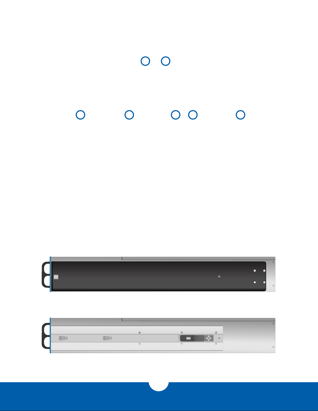
1.6 REAR VIEW
5 4
1 - Power Supply Unit (PSU) Modules
The Jupiter Expander Rack 835 has two externaly mounted redundant
and hot-swappable power supply unit (PSU) modules for increased
reliability and easy serviceability. When both modules are functioning
properly, they automatically balance the load of the entire Jupiter unit.
2 - Data Connections
The Jupiter Expander Rack 835 has two external mini-SAS (SFF-8088)
data connections. Each connection carries four SAS 6Gb/s data channels
through it. Either connection can function as a host link or an expansion
link, though one must always be a host link.
3 - Fan Modules
The Jupiter Expander Rack 835 has two externaly mounted swappable
fan modules for easy serviceablity.
1.7 SIDE VIEW
Side view with rail attached
263
31
4 - Power Switch
The Jupiter Expander Rack 835 has a rear mounted and easily
accessible power switch.
5 - Top Cover Thumbscrew
This screw must be loosened in order to remove the top cover for
servicing.
6 - Service Port
The Jupiter Expander Rack 835 has an RS-232 serial port for service.
This port is generally not used as all service tasks can be done via the
Jupiter Command Center application.
Side view with rail removed
OWC Jupiter Mini-SAS intrOduCtiOn
5

1.5 INTERNAL VIEW
1 - Backplanes
2 - Backplane mini-SAS Connections
3 - System Board mini-SAS Connections
4 - Fan Modules
5 - System Board
6 - Mini-SAS Data Cables
2
1
6
4
6
5
4
3
OWC Jupiter Mini-SAS intrOduCtiOn
6
SYSTEM SETUP
2.1 RAIL INSTALLATION
The Jupiter Expander Rack 835 storage system comes with rack mount slide rails attached to the sides of the unit
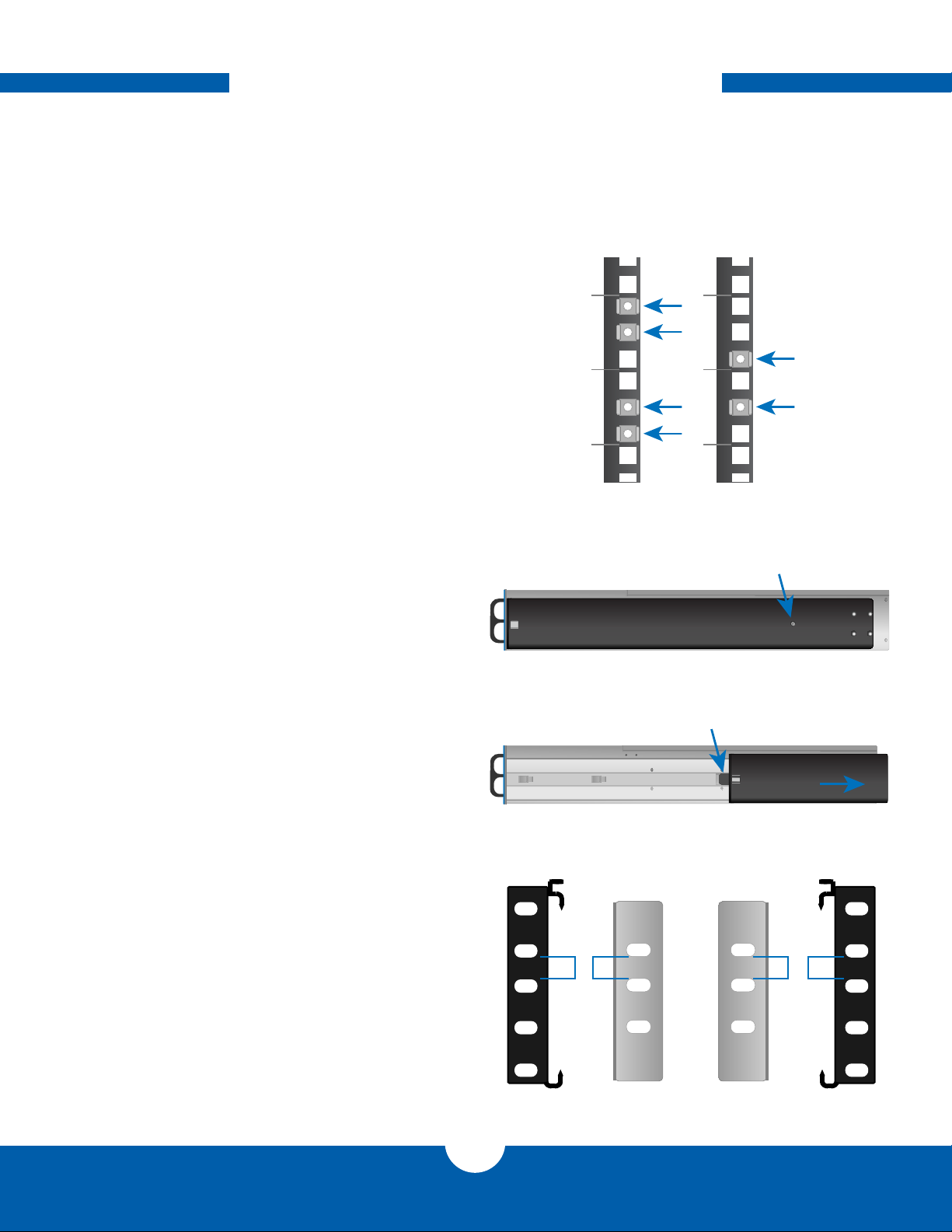
and the necessary screws and cage nuts for installing into 4-post square-hole rack systems. To install the slide rail
brackets into your rack, do the following:
1. The Jupiter Expander Rack 835 requires two
rack units of space, take note of which units
on your rack that you will install Jupiter into.
2. Install the included cage nuts into your rack
using Figure 2.1a as a guide for cage nut
placement within the 2U's that have been
designated for Jupiter.
Front Placement Rear Placement
Figure 2.1a
3. On the Jupiter unit, remove the securing
screw from the rail on the left and right sides
as seen in Figure 2.1b.
4. Once the securing screws have been
removed, remove the rail arm from the Jupiter
unit by sliding it toward the rear of the unit as
seen in Figure 2.1c. When the rail arm stops,
push the release tab while continuing to slide
the rail arm off. After removing the rails, set
them aside taking note of the side from which
they were removed.
5. Remove the rail arm extensions from the
accessories box and match them to the
rails. Use Figure 2.1d as a guide for proper
matching of rails and the extension pieces.
Figure 2.1b
Push to release
Figure 2.1c
Left Rail
Shorter gap Shorter gap
Left Rail
Extension
Right Rail
Extension
Securing screw
Slide
Right Rail
Figure 2.1d
OWC Jupiter Mini-SAS SySteM Setup
7
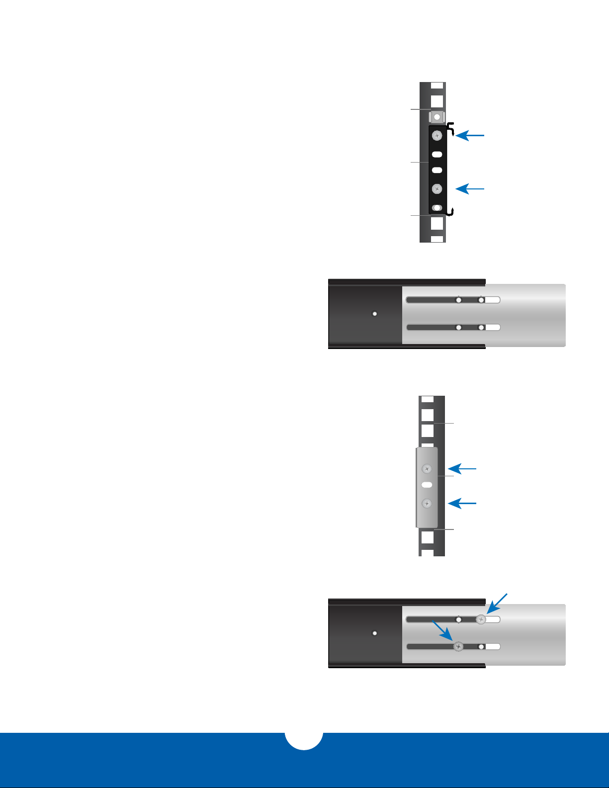
6. Install the front rails first making sure the
bottom of the rail lines up with the bottom of
the designated rack units. Using Figure 2.1e
as a guide secure the rail using two of the
included M5 pan head screws.
7. Before securing the rear rail extension to
the back of your rack, make sure to slide the
extension into the rail as seen in Figure 2.1f.
8. Secure the rear rail extension to your rack use
two of the included M5 pan head screws as
seen in Figure 2.1g.
9. After securing the rear rail extension to your rack,
secure the rail extension to the rail using two of
the included M5 pan head screws as shown in
Figure 2.1h.
10. After repeating the steps for the other side,
you can now move on to installing the
Jupiter storage system into the rack as found
in section 2.2 Unit Rack Installation and
Removal on the next page.
Figure 2.1e
Figure 2.1f
Figure 2.1g
Figure 2.1h
OWC Jupiter Mini-SAS SySteM Setup
8
 Loading...