

Page 1

owa23X Platform Integrator’s Manual
BOK-100 1065-C-owa23X Platform Integrator's Manual
i
owa23X Platform Integrator's Manual
Page 2
owa23X Platform Integrator’s Manual
BOK-100 1065-C-owa23X Platform Integrator's Manual
ii
The products described in this manual conform to the essential Requirements in
Radio and Telecommunications Terminal Equipment Directive 1999/5/EC, covering
requirements included in EMC directive 2004/108/EC Low Voltage Directive 2006/95/EC as well
as any other applicable requirements as those from RoHS Directive 2002/95/EC
The information contained in this document is the proprietary information of
owasys. The
contents are confidential and any disclosure to persons other than the officers, employees,
agents or subcontractors of the owner or licensee of this document, without the prior written
consent of
owasys, is strictly prohibited.
Furthermore, no portion of this publication may be reproduced, stored in a retrieval system, or
transmitted in any form or by any means, electronic or mechanical, including photocopying and
recording, without the prior written consent of
owasys, the copyright holder.
Additional information at www.owasys.com
.
Edition: January 2010
owasys publishes this manual without making any warranty as to the content contained herein.
Further
owasys reserves the right to make modifications to this manual due to typographical
errors, inaccurate information, or improvements to programs and/or equipment at any time and
without notice. Such changes will, nevertheless be incorporated into new editions of this
manual.
All rights reserved.
©
owasys, 2010
Document number: BOK-100 1065-C
Trademarks
© ARM is a registered trademark of ARM Limited.
Linux is a registered trademark of Linus Torvalds
DISPOSAL OF OLD ELECTRICAL & ELECTRONIC EQUIPMENT (APPLICABLE IN THE
EUROPEAN UNION AND OTHER EUROPEAN COUNTRIES WITH SEPARATE COLLECTION
SYSTEMS).
This product shall not be treated as household waste. Instead it shall be handed over to the
applicable collection point for the recycling of electrical and electronic equipment. By
ensuring this product is disposed of correctly, you will help prevent potential negative
consequences for the environment and human health, which could otherwise be caused by inappropriate
waste handling of this product. The recycling of materials will help to conserve natural resources. For
more detailed information about recycling of this product, please contact your local council, your waste
disposal service or the distributor where you purchased the product.
Page 3

owa23X Platform Integrator’s Manual
BOK-100 1065-C-owa23X Platform Integrator's Manual
iii
Table of Contents
1
SAFETY AND OTHER PRECAUTIONS ...............................................................................1
1.1 GENERAL .......................................................................................................................... 1
1.2 OWA23X CONNECTIONS ....................................................................................................1
1.3 EMC INSTRUCTIONS ......................................................................................................... 1
1.4 EXPOSURE TO RF ENERGY................................................................................................1
1.5 ANTENNA CARE AND REPLACEMENT. ................................................................................. 2
1.6 ELECTRONIC DEVICES....................................................................................................... 2
1.7 BLASTING AREAS ..............................................................................................................2
1.8 CHILDREN.........................................................................................................................2
1.9 EXPLOSIVE ATMOSPHERES................................................................................................ 2
1.10 HANDLING THE DEVICE .................................................................................................. 3
1.11 FOR OWA23X/B............................................................................................................. 3
1.12 ACCESSORIES ...............................................................................................................3
2 INTRODUCTION....................................................................................................................4
2.1 OVERVIEW........................................................................................................................ 4
2.2 WHAT IS THE OWA23X PLATFORM...................................................................................... 4
2.3 OWA23X MODELS .............................................................................................................5
2.4 ABBREVIATIONS ................................................................................................................5
2.5 NOTES, WARNINGS AND ESD............................................................................................6
3 GETTING STARTED WITH THE DEVELOPMENT KIT .......................................................6
3.1 INTRODUCTION..................................................................................................................6
3.2 DEVELOPMENT BOARD DESCRIPTION.................................................................................6
3.2.1 Development Board Connectors ............................................................................. 7
3.2.2 Development Board LEDs, Switches & Pots........................................................... 8
3.3 MOUNTING THE OWA23X DEVELOPMENT KIT......................................................................8
3.4 DEVELOPMENT KIT SOFTWARE SET UP..............................................................................9
3.4.1 Installing and Using the Cross Compiler ................................................................. 9
3.5 CONNECTING OWA23X TO A PC....................................................................................... 10
3.5.1 Ways of Booting.....................................................................................................10
3.5.2 Windows HyperTerminal .......................................................................................11
3.5.3 Linux Minicom........................................................................................................11
3.5.4 Updating owa23X Boot loader, Kernel or File system...........................................12
3.6 DOWNLOAD A DEMO APPLICATION ................................................................................... 12
4 OWA23X DESCRIPTION .................................................................................................... 14
4.1 OWA23X PHYSICAL DESCRIPTION.................................................................................... 14
4.2 HARDWARE FEATURES....................................................................................................15
4.2.1 Microprocessor and Memory................................................................................. 15
4.2.2 GSM/GPRS System ..............................................................................................15
4.2.3 GPS .......................................................................................................................16
4.2.4 30 Pin Multipurpose Connector.............................................................................17
4.2.5 Power Supply.........................................................................................................18
4.2.6 Fusing....................................................................................................................18
4.2.7 Digital Inputs/Outpus .............................................................................................18
4.2.8 Odometer / Counter............................................................................................... 20
4.2.9 Vout Power Output ................................................................................................20
4.2.10 Analog Inputs......................................................................................................... 21
4.2.11 CAN .......................................................................................................................21
4.2.12 RS485....................................................................................................................22
4.2.13 RS232....................................................................................................................22
4.2.14 Ground...................................................................................................................23
4.2.15 Audio...................................................................................................................... 23
4.2.16 Ethernet 10-BaseT.................................................................................................24
4.2.17 LEDs......................................................................................................................24
4.2.18 SIM Card Holder.................................................................................................... 25
Page 4

owa23X Platform Integrator’s Manual
BOK-100 1065-C-owa23X Platform Integrator's Manual
iv
4.2.19
Battery Back-up.....................................................................................................25
4.2.20 Internal Temperature.............................................................................................28
4.2.21 System Time..........................................................................................................28
4.2.22 Watchdog............................................................................................................... 28
4.2.23 Protection............................................................................................................... 29
4.2.24 Movement Sensor..................................................................................................29
4.3 FUNCTIONAL STATES....................................................................................................... 30
4.4 POWER MANAGEMENT..................................................................................................... 30
4.4.1 Power Modes.........................................................................................................31
4.4.2 Power Consumption ..............................................................................................34
4.5 FIRMWARE SPECIFICATIONS.............................................................................................35
4.5.1 General Description of Firmware...........................................................................35
4.5.2 User ‘Hard Disk’.....................................................................................................36
4.5.3 Starting to Develop the Customer Application....................................................... 36
4.5.4 Loading the Customer Application.........................................................................39
4.5.5 Available APIs........................................................................................................39
4.5.6 Power Management...............................................................................................40
4.5.7 RS232 Driver.........................................................................................................40
4.5.8 Software Application Notes ................................................................................... 40
5 INSTALLATION...................................................................................................................41
5.1 SIM CARD INSTALLATION................................................................................................. 41
5.1.1 Open Cover ........................................................................................................... 41
5.1.2 Insert SIM .............................................................................................................. 42
5.1.3 Close Cover........................................................................................................... 42
5.2 ANTENNA INSTALLATION ..................................................................................................43
5.2.1 Location.................................................................................................................43
5.2.2 Antenna Tuning .....................................................................................................43
5.2.3 Antenna Cable Routing ......................................................................................... 43
5.3 POWER AND SIGNAL CONNECTION...................................................................................43
5.4 CHOOSING A LOCATION ...................................................................................................44
5.5 MOUNTING THE UNIT .......................................................................................................44
5.6 ANTENNA CONNECTOR PROTECTION................................................................................44
6 TECHNICAL DATA SUMMARY.......................................................................................... 46
7 OWA23X FIRMWARE ADVANCED CONFIGURATION.................................................... 50
7.1 ETHERNET......................................................................................................................50
7.1.1 Ethernet interface activation..................................................................................50
7.1.2 Ethernet interface deactivation..............................................................................52
7.2 ROUTING AND FIREWALL TOOLS.......................................................................................52
7.3 REMOTE FIRMWARE UPGRADE.........................................................................................53
8 REFERENCES..................................................................................................................... 54
Page 5

owa23X Platform Integrator’s Manual
BOK-100 1065-C-owa23X Platform Integrator's Manual
v
Index of Figures
Figure 3.2.1 Development board physical description.................................................................... 6
Figure 4.1.1 owa23X Physical description ..................................................................................... 14
Figure 4.2.1.1Memory arrangement.............................................................................................. 15
Figure 4.2.1.1 . 30 Pin Mating Connector with cable..................................................................... 17
Figure 4.2.1.2 . 30 Pin Connector pin functions............................................................................. 17
Figure 4.2.7.2 Digital output typical loads .....................................................................................19
Figure 4.2.7.3 Driving loads from user supply .............................................................................. 20
Figure 4.2.12.1 Adapting sensors to Analog Inputs....................................................................... 21
Figure 4.2.12.1 owa23X RS485 bus................................................................................................22
Figure 4.2.19.2.1 Battery back-up installation. ............................................................................. 27
Figure 4.3.1 Functional states. ...................................................................................................... 30
Figure 4.5.1.1 owa23X Software structure .................................................................................... 35
Figure 4.5.1.3.1 File system structure........................................................................................... 35
Figure 4.5.2.1 User hard disk structure ........................................................................................ 36
Figure 5.1.1.1 Opening front cover ................................................................................................ 41
Figure 5.1.2.1 Inserting SIM........................................................................................................... 42
Figure 5.1.3.1 Latches.................................................................................................................... 42
Figure 5.6.1 Protecting antenna connectors................................................................................. 45
Index of Tables
Table 2.3.1 owa23X Models Table .................................................................................................... 5
Table 2.4.1 Abbreviations list ........................................................................................................... 5
Table 3.2.1 Development board connectors list .............................................................................. 7
Table 3.2.2 Development board J4 pin out ...................................................................................... 7
Table 3.2.3 Development board J5 pin out ...................................................................................... 8
Table 3.2.2.1 Development board LED, switch and pot description................................................ 8
Table 4.2.2.1.1 GSM antenna connector ........................................................................................ 16
Table 4.2.3.11 GPS antenna connector.......................................................................................... 16
Table 4.2.4.1 30 Pin connector pin functions................................................................................. 17
Table 4.2.5.1 Power supply connector pins function..................................................................... 18
Table 4.2.5.1 Digital I/O pin out ...................................................................................................... 18
Table 4.2.5.1 Digital I/O signal levels............................................................................................. 19
Table 4.2.5.2 Cross Platform I/O signal mapping.......................................................................... 20
Table 4.2.5.1 Analog Inputs............................................................................................................ 21
Table 4.2.5.1 CAN pin out ............................................................................................................... 22
Table 4.2.5.1 RS485 pin out............................................................................................................ 22
Table 4.2.5.1 RS232 pin out............................................................................................................ 22
Table 4.2.5.1 Audio pin out ............................................................................................................. 23
Table 4.2.5.1 Ethernet pin out ........................................................................................................24
Table 4.2.16.1 owa21I-ETH: Yellow LED indications ..................................................................... 24
Table 4.2.16.2 owa21I-ETH: Green LED indications ...................................................................... 24
Table 4.2.17.1 owa23X Green LED indications............................................................................... 24
Table 4.2.172 owa23X Yellow LED indications............................................................................... 25
Table 4.2.17.3 owa23X Orange LED indications............................................................................. 25
Table 4.3.1 owa23X Functional states............................................................................................ 30
Table 4.4.1.4 Dedicated internal battery duration ......................................................................... 32
Table 4.4.2 Power consumption..................................................................................................... 34
Table 6.1 General specification...................................................................................................... 46
Table 6.2 Mechanical description .................................................................................................. 46
Page 6

owa23X Platform Integrator’s Manual
BOK-100 1065-C-owa23X Platform Integrator's Manual
vi
Table 6.3 Power interface .............................................................................................................. 46
Table 6.4 GSM/GPRS specifications............................................................................................... 47
Table 6.5 Ethernet specifications .................................................................................................. 47
Table 6.6 GPS specifications ..........................................................................................................48
Table 6.7 Environmental specifications......................................................................................... 49
Table 6.8 Battery backup ............................................................................................................... 49
Page 7

owa23X Platform Integrator’s Manual
BOK-100 1065-C-owa23X Platform Integrator's Manual
1
1 Safety and other precautions
1.1 General
IMPORTANT: FOR THE EFFICIENT AND SAFE OPERATION OF YOUR owa23X
DEVICE, READ THIS INFORMATION BEFORE USE!
Care must be taken when handling the unit. It must not be dropped or exposed
to excessive heat.
Only authorized staff can disassemble the product.The product may be opened
to install the SIM card OBSERVING the ESD precautions described in this
document. Otherwise if the product was disassembled by non-authorized
people, and/or no ESD precautions are taken the warranty is no longer valid.
Do not force objects into the joints around the cover. This may damage the
seals. Only use the specified tools to open the unit.
If the product is exposed to severe conditions beyond the limits specified in
Environmental Specifications, the product could be damaged.
Keep the device away from radiators and heat sources.
Do not clean the device when powered. Clean it with a damp soft cloth, and do
not use solvents.
1.2 owa23X Connections
The highest internal voltage applied to the owa23X unit can be 40Vdc and
complies with low voltage European directive (See Chapter 4.2.5 Power Supply).
The power supply can be made with a battery or continuous voltage supply with
reinforced isolation, and limited in power to a maximum of 8 A and 100 VA.
Before you connect the device to a power supply, check the voltage and current
rating to ensure that the required ones match the available power source.
Exceeding the specified input range may cause unexpected operation and/or
irreversible damage to owa23X.
To remove the device from all power sources turn the device off and disconnect
it from the power supply.
Be sure that nothing rests on the connected cables and that the cables are not
located where they can be tripped over or stepped on.
Applying loads outside of the range specified may result in unintended
operation and/or possible permanent damage to owa23X. Read section 4.2.7
carefully before connecting any load to the outputs. If there is any uncertainty,
please contact owasys Customer Support.
1.3 EMC Instructions
Use shielded signal cables to ensure that you maintain the appropriate EMC
classification for the intended environment.
Keep cables as short as possible, lengths not longer than 3 meters are
recommended.
1.4 Exposure to RF Energy
Minimize RF energy exposure by limiting the duration of GSM calls and
operating the unit efficiently.
Page 8

owa23X Platform Integrator’s Manual
BOK-100 1065-C-owa23X Platform Integrator's Manual
2
The antenna must be mounted in such a position that no part of the human body
rests close to any part of the antenna.
The product is intended to be used with an external GSM antenna, located at
least at 20 cm. away from any part of the human body. Those installations not
complying with this statement are responsible for providing SAR measurement
reports and corresponding declaration.
Do not hold the antenna during a call since it affects call quality and can cause
the module to operate at a higher power level than needed.
1.5 Antenna Care and Replacement.
Do not use the product with a damaged antenna because when the antenna
comes into contact with the skin, a minor burn may result. Replace the antenna
immediately.
Use only antennas that are according to the technical specifications. Antennas
that do not fulfil the specifications could damage the product and may
contravene local RF emissions regulations or invalidate type approval.
1.6 Electronic Devices
Most electronic devices are shielded from RF energy. However RF energy may
cause some malfunctioning of improperly shielded electronic devices.
When the product is mounted in a vehicle, check your vehicle to determine that
all on board electronic equipment is adequately shielded from RF energy.
In the same way, when the product is in the proximity of medical devices
(hospitals, etc) check with the manufacturer of medical equipment to determine
if they are properly shielded.
This equipment should never be operated on an aircraft.
1.7 Blasting Areas
To avoid interfering with blasting operations, turn the unit OFF in these kinds of
areas or in areas ported “turn off your two way radio”.
Construction crew often uses remote control RF devices to set off explosives.
1.8 Children
Do not allow children to play with owa23X. It is not a toy and they could hurt
themselves or others. Children could also damage the unit.
1.9 Explosive Atmospheres
Do not operate this product in environments containing explosive materials or
vapour. This includes petrol service stations.
The unit accessories could generate sparks that can cause an explosion or fire
resulting in bodily injury or even death.
To avoid interfering with blasting operations, turn the unit off in areas posted
“blasting area”.
Do not transport or store flammable gas, liquid or explosives, in the
compartment of your vehicle which contains owa23X or its accessories.
Page 9

owa23X Platform Integrator’s Manual
BOK-100 1065-C-owa23X Platform Integrator's Manual
3
1.10 Handling the Device
Observe the following safe-handling guidelines to prevent damage to owa23X:
When setting up the device for work, place it on a flat level surface.
Protect the device from environmental hazards such as extreme
temperatures and overexposure to sunlight.
When you move your device between environments with very
different temperature and/or humidity ranges, condensation may
form on or within the device. To avoid damaging it, allow sufficient
time for the moisture to evaporate before using the device.
When taking the device from low-temperature conditions into a
warmer environment or from high-temperature conditions into a
cooler environment, allow the device to acclimate to room
temperature before turning on power.
When disconnecting a cable, pull on its connector or on its strain-
relief loop, not on the cable itself. As you pull out the connector,
keep it evenly aligned to avoid bending any connector pins. Also,
before you connect a cable make sure both connectors are correctly
oriented and aligned.
When opening the device to insert the SIM card, ensure that the
device is dry so that moisture doen not enter. The unit contains ESD
sensative electronics so follow appropriate ESD precautions.
1.11 For owa23X/b
These models include the optional lithium-ion battery backup.
Do not dispose off the battery along with household waste. Contact your local
waste disposal agency for the address of the nearest battery disposal site,
always respecting the environmental regulations in place.
The battery poses a burn hazard if you handle it improperly. So do not
disassemble or handle it. If the battery is damaged, electrolyte may leak from
the cells and may cause personal injury.
Keep the battery away form children.
When the battery is heated to excessive temperatures (above 60ºC), its cells
could explode or vent, posing a risk of fire.
To maximise the battery capacity, it is recommendable to use it at room
temperatures. At lower temperatures the battery life is reduced.
Turn the equipment OFF always before removing or replacing the battery.
1.12 Accessories
Use only accessories that are compatible with your owa23X equipment, and
recommended by owasys. Using inappropriate accessories can generate health
risks or can damage the equipment because of incompatible devices and
guarantee will not be valid.
There may be a risk of explosion if battery is replaced by an incorrect type.
Page 10

owa23X Platform Integrator’s Manual
BOK-100 1065-C-owa23X Platform Integrator's Manual
4
2 Introduction
2.1 Overview
The owa23X
Integrators Manual
describes how to install, set up, and configure
owa23X Platform products. This platform covers the products described in
chapter2.3.
This document focuses on the explanation of the basic operation that is
common to all of the owa23X devices. Whenever a feature is supported by the
whole owa23X family, model is referred as owa23X.
All the devices are provided with a small dedicated internal battery for RTC
back-up and owa23A models are also provided with GPS data backup. In
addition to this, the devices can be provided with high capacity internal battery
backup as an option. In this case, the products are labelled with a “/b” at the
end, e.g.: owa23A/b. The high capacity battery can also be supplied separately
(POP 100 2100).
This first section provides a brief overview of the products followed by a
“Getting Started” chapter. Further sections go into more detail on the hardware
specifications and various firmware functions available to the development of
the user application. Application notes, technical specifications,
troubleshooting, and a peripheral devices reference, complete this manual.
2.2 What is the owa23X Platform
The owa23X range of products provides a powerful platform for management of
geographically distributed equipment. The owa23x units integrate a GSM/GPRS
communication system with embedded IP functionality, allowing an efficient
and bi-directional transmission of information across the cellular wireless
network. Additionally, the owa23A unit includes a GPS receiver for reception of
positioning information.
The basic features that are common to this family of products are:
GSM-GPRS, quad–band (GSM850-900-1800-1900).
GPRS Class B, Class 10 (4+2) system and 07.10.
Stack TCP/IP for transparent Internet connection.
User-friendly programming environment with a complete set of APIs.
Extensive range of external serial interfaces, digital and analog I/Os.
Additionally, different models may include specific hardware or functionality:
GPS, 16 channel
CAN
Audio interface for speaker and microphone
Ethernet 10baseT
Page 11
owa23X Platform Integrator’s Manual
BOK-100 1065-C-owa23X Platform Integrator's Manual
5
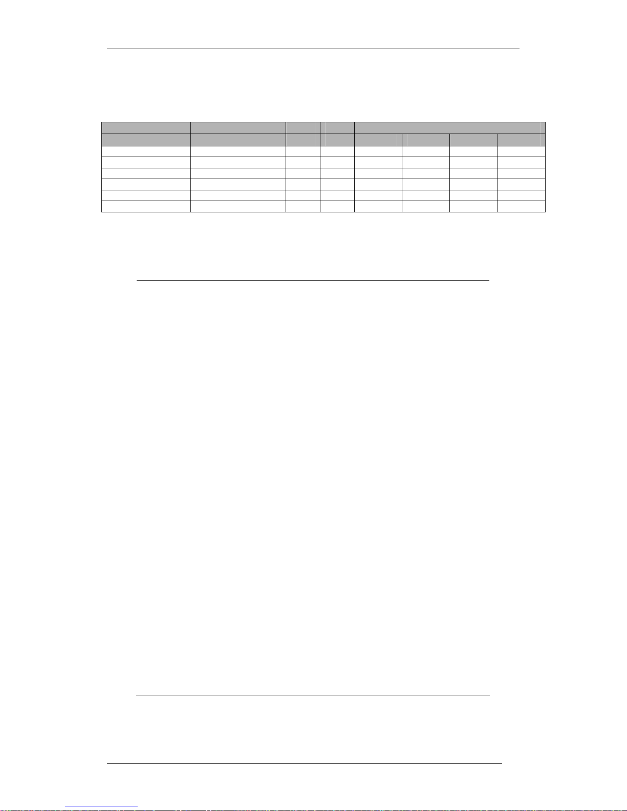
2.3 owa23X Models
Note: the standard model is owa23A-CAN. Other models are only available for special orders.
Please contact your distributor for more information.
Product Code Name CAN GPS 30 Way Connector Pin Options
A3 B3 D3 E3
POP 100 3000#01 owa23A • MICP MICN SPKP SPKN
POP 100 3001#01 owa23I MICP MICN SPKP SPKN
POP 100 3002#01 owa23A-CAN • • MICP MICN SPKP SPKN
POP 100 3010#01 owa23A-ETH • ETH-RX+ ETH-RX- ETH-TX+ ETH-TXPOP 100 3011#01 owa23I-ETH ETH-RX+ ETH-RX- ETH-TX+ ETH-TXPOP 100 3012#01 owa23A-ETH-CAN • • ETH-RX+ ETH-RX- ETH-TX+ ETH-TX-
Table 2.3.1 owa23X Models Table
2.4 Abbreviations
API Application Programming Interface
CEP Circular Error Probability
CPU Central Processing Unit
CTS Clear to Send
DCD Data Carrier Detect
DSR Data Send Ready
DTE Data Terminal Equipment
DTR Data Terminal Ready
GND Ground
GPIO Generl Purpose Input Output
GPRS General Packet Radio Service
GPS Global Positioning System
GSM Global System Mobile
HW Hardware
MIPS Millions of Instructions Per Second
MMU Memory Management Unit
NA Not Available
NC Not Connected
O&M Operation and Maintenance
OS Operating system
PWM Pulse Width Modulation
RI Ring Indicator
RTC Real Time Clock
RTS Request to Send
RX Reception
SAR Specific Absorption Rate
SIM Subscriber Identity Module
SMS Short Message System
SW Software
TTY TeleType Writer
TX Transmission
USB Universal Serial Bus
VSWR Voltage Standing Wave Ratio
Table 2.4.1 Abbreviations list
Page 12
owa23X Platform Integrator’s Manual
BOK-100 1065-C-owa23X Platform Integrator's Manual
6
2.5 Notes, Warnings and ESD
Notes – Provides additional information about the products. It normally shows
the difference between the owa2X family products.
Warning – Alerts you to situations that could cause hardware damage or
software error.
ESD – Alerts you to parts that are sensitive to electrostatic discharge damage.
In these cases the product must be handled in appropriate ESD safe conditions,
3 Getting Started with the Development Kit
3.1 Introduction
This section explains the steps to install and configure the development kit and
begin with the setup of the customer application. The development kit offers
the possibility of testing the developed applications and easy control and test of
the owa23X interfaces.
This section starts with a description of the development board and then with
the steps for mounting and connecting the kit, and then the software set up
procedure.
3.2 Development Board Description
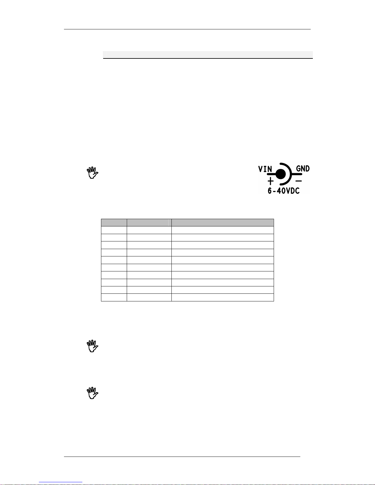
Following figure shows the layout of the Development Board:
Figure 3.2.1 Development board physical description
Page 13
owa23X Platform Integrator’s Manual
BOK-100 1065-C-owa23X Platform Integrator's Manual
7
3.2.1 Development Board Connectors
Number Connector
X3 Power Supply DC Jack.
J1 Screw Terminal for owa23 row A
J2 Screw Terminal for owa23 row B
J3 Screw Terminal for owa23 row C
J4 Signals for external use.
J5 DB9 for RS232 on UART0 (note: null modem pinout)
J6 Speaker output (for headset).
J7 Microphone input (for headset).
J8 Ethernet jack.
Table 3.2.1 Development board connectors list
J1, J2 and J3 are for connecting to the owa23X. Connect the cable as shown in
section 4.2.4.
Power can be connected either to X3, or pins 10 (+VIN)
and 9 (GND) of J4. For connecting power to X3, ensure
that the positive pin is in the centre, and ground is on the
outer conductor, as follows:
J4 provides screw terminal connections for the various signals on the
development board. Pin-outs are as follows:
Pin Signal Function
J4-1 CAN0H CAN bus 0
J4-2 CAN0L CAN bus 0
J4-3 RS485A RS485 bus
J4-4 RS485B RS485 bus
J4-5 ADIN1 Analog input 1
J4-6 ADIN0 Analog input 0
J4-7 VOUT 4.5V supply output (max 100mA)
J4-8 ON/OFF ON/OFF input (low = OFF)
J4-9 GND Ground
J4-10 VIN Positive power input (6-40 VDC)
Table 3.2.2 Development board J4 pin out
If using external signals for ADIN0 or ADIN1, then leave the switches SW1-1,
SW1-2, SW1-3 and SW1-4 in the OFF position.
Note: do not draw more than 50mA from the 4V5 output as this is also powering
other items on the development board.
If using external signals for I/O-0 to I/O-7, then leave the switches SW2 & SW3
in the OFF position.
J5 provides a DB9 connection for UART0 RS232. J5 has the following pin out.
Note that this is a null modem pinout and must be used with the cable supplied
in the development kit.
Page 14
owa23X Platform Integrator’s Manual
BOK-100 1065-C-owa23X Platform Integrator's Manual
8
Pin Signal Function
J5-1 - J5-2 RX RS232 Tx
J5-3 TX RS232 Rx
J5-4 - J5-5 GND Ground
J5-6 - J5-7 RTS RS232 RTS
J5-8 CTS RS232 CTS
J5-9 - -
Table 3.2.3 Development board J5 pin out
Note that to use RS485 or CAN, a 120Ω termination resistor must be placed at
each end of the network. One of them may be mounted by inserting a 120Ω
leaded resistor in terminals 1 & 2 or 3 & 4 of J4. The other termination resistor
must be mounted at the other end of the network.
3.2.2 Development Board LEDs, Switches & Pots
Following table shows the LED indicators, Switches and Potentiometers on the
Development Board. The LEDs enable monitoring of the various supplies and
outputs, and the switches and pots enable activation of the various inputs.
LED Description
I/O-0..I/O-7 ON when outputs 0 to 7 are activated.
VOUT Indicates that 4.5V supply is available.
VIN Indicates VIN power is applied.
Switch Description
SW1-1 Connect ADIN0 to light dependent resistor LDR.
SW1-2 Connect ADIN1 to temperature sensor TEMP.
SW1-3 Connect ADIN0 to potentiometer RV1.
SW1-4 Connect ADIN1 to potentiometer RV2.
SW2-1..4 Activate inputs 0 to 3 (note active = input low).
SW3-1..4 Activate inputs 4 to 7 (note active = input low).
Pot Description
RV1 Adjust voltage for ADIN0 (when SW1-3 selected).
RV2 Adjust voltage for ADIN1 (when SW1-4 selected).
Table 3.2.2.1 Development board LED, switch and pot description
Do not select
both
the LDR and RV1 on SW1 or the measurement on ADIN0 will
not be correct. The same applies to TEMP and RV2 for ADIN1.
Note: SW2 and SW3 pull the I/O pins to ground, so the LEDs will be ON.
3.3 Mounting the owa23X Development Kit
The steps for mounting the components in owa23X are the following:
GSM & GPS Antenna: Connect the antenna supplied by following the colour
coding and/or labels.
RS-232 Serial cable: This cable is a null-modem type. It should be connected to
the RS-232 DB9 connector in the developer’s board. The other end of the cable
should be connected to a personal computer.
Page 15

owa23X Platform Integrator’s Manual
BOK-100 1065-C-owa23X Platform Integrator's Manual
9
Multipurpose connector cable: This connector carries power and I/O signals.
The 30 pins in this connector should be supplied pre-connected to the
development kit, but if not then follow the pin-out in section 4.2.4 to connect the
30 wires to J1, J2 and J3 on the development kit.
AC/DC Power supply: The provided AC/DC power supply adaptor can be
connected to developers board connector X3, and to a suitable AC main outlet.
Alternatively a laboratory power supply can be connected to pins 10 (+VIN) and
9 (GND) of J2 connector. In this case set the voltage to 12V and the current limit
to 2A.
SIM card: See section 5.1 for details on how to install the SIM card.
Ethernet Cable: If your owa23X has the ETH option, then connect the Ethernet
Cable between the personal computer and the Ehernet connector RJ45 one the
development kit. The supplied cable is cross connected.
3.4 Development Kit Software Set Up
Instructions found in the remainder of this chapter show how to configure the
owa23X unit using the provided files in the development kit CD. The
Development Kit CD includes the following software:
The necessary files to install a cross compiler for ARM that
contains the header files of the APIs.
Demo application notes (source files, header files and makefiles).
Current firmware version (boot, kernel and file system SW)
The PC requirements for using the offered applications are (as follows):
Linux Operating System (min. Kernel 2.4.18 recommended)
Free disk space (minimum needed): 0.5GBytes
Linux Development tools installed according to the customer’s
preferences, as KDeveloper (or similar).
Note - To develop applications for the owa23X platform the user
must have knowledge of programming in C and the Linux
environment.
3.4.1 Installing and Using the Cross Compiler
In order to help the integrator, a compiler is included in the Development Kit
CD. The cross compiler allows the developer to easily create binary files that
can be directly executed in owa23X. In order to install the ARM cross compiler,
follow the steps listed below.
Copy the content of the
/crosscompiler
directory to your PC.
Login as root.
Run the install script:
./install.sh
to install the cross compiler in
/usr/local/arm/[version]/ automatically.
Include in the
/etc/profile
file the following line:
PATH=$PATH:/usr/local/arm/[version]/bin
.
Reboot the machine.
[version]
must be replaced for the current version number of the
compiler you will find in the CD.
Page 16

owa23X Platform Integrator’s Manual
BOK-100 1065-C-owa23X Platform Integrator's Manual
10
To know more about how to use the cross compiler go to help that will
print all available functions.
$arm-linux-gcc --help
It is recommended to use the compiler included in the CD, or provided by
owasys. This compiler is a standard GNU tool available in the web, and although
it is possible to use other appropriate compilers (adapted to owa23X micro and
with the required header files of the APIs), owasys is not responsible for
possible compilation errors or any other malfunction.
Changes in owa2x firmware, due to SW improvements etc, may require a new
version of the cross compiler to be installed. If that is the case the previous
version should be removed from the system.
For uninstalling the cross compiler:
Remove all cross compiler files,
rm –rfv /usr/local/arm
From
/etc/profile
file remove the following line
PATH=$PATH:/usr/local/arm/[version]/bin.
3.5 Connecting owa23X to a PC
Either Linux OS or Windows OS can be used to connect to the device from a
Personal Computer (PC) through serial port. The required configuration
parameters are the following:
Bit Rate: 115200 bps
Data Bits: 8
Parity: none
Bit Stop: 1
Flow Control: None
Note that a null modem cable as supplied in the DK should be used.
3.5.1 Ways of Booting
In the “normal” booting process, after switching on the device, the boot loader
starts to decompress the file system and kernel from Flash memory and store
it to RAM memory. While doing this operation, the system sends through the
RS232 DB-9 connector (ref. 3 of fig. 3.3.1.1) the message: “Booting…” . At the
end of this process the system asks the user for a login and password.
Booting process can be modified by pressing and holding the ENTER key during
switch ON of the device. The boot loader then stops in commands mode, with
the prompt:
bootloader%%
. The allowed commands are:
boot
: The system boots in the “normal” way.
bootl1
: The system boots in the “normal” way but in verbose mode
so that system messages are sent to serial port
bootl2
: The system boots, but skipping the copy of
/home/@sysinit
directory. See section 7 for further details.
reboot
: The system reboots again. It is useful when upgrading
bootloader code, so that a power cycle is not needed for the new
boot code to be executed.
Page 17

owa23X Platform Integrator’s Manual
BOK-100 1065-C-owa23X Platform Integrator's Manual
11
erasejffs
: Utility to format the Flash memory. Be careful, as all the
contents of the Flash memory (everything stored under
/home
directory) will be erased.
loadx [boot, kernel, ramdisk]
: Utility to download new bootloader,
kernel or filesystem respectively. See 3.5.4 for further details
If no command is issued at the prompt
Bootloader%%
, the device will stay in
this situation for a maximum of 30 minutes. Then, it will continue with the
normal boot sequence.
3.5.2 Windows HyperTerminal
Use Windows HyperTerminal to connect owa23X to the PC configuring the
serial port parameters to the values indicated in section 3.5.
Switch on the owa23X. Once the File System and Kernel are loaded in RAM
memory, the device waits for the user to enter a valid user name to log in. This
user name is
root
and it has no password.
Once logged in, the user is in the owa23X file system which has the directory
structure described in section 4.5.1.3. As stated in that section, user
applications should be stored under
/home
directory, in a non-volatile memory.
Any other directory outside
/home
uses volatile RAM memory and should be
preferred to store dynamic data.
To transfer a file from the PC to the owa23X, change to
/home
directory or to
the directory where the file is to be stored (
cd /home or cd /directory_name
),
type
lrz
command and choose
Transfer-> Send File…
option of the
HyperTerminal and zmodem protocol.
To transfer a file from the device to the PC, change to the directory where the
file is, then type
lsz
command indicating the name of the file (
lsz file_name
) and
choose the
Transfer -> Receive File…
option of the HyperTerminal. File
transfer protocol is zmodem in both cases.
When a file is transferred using Windows HyperTerminal, the file permissions
are modified automatically. To revert to the proper file permissions inside the
owa22X, use the command:
chmod a+x file_name
(for executing permissions).
chmod a+r file_name
(for reading permissions).
chmod a+w file_name
(for writing permissions).
3.5.3 Linux Minicom
Run the
minicom
program and configure the serial port parameters to the
values indicated in section 3.5.
Minicom
help is shown by typing Ctrl-A Z.
Serial port device files
(/dev/ttyS0, /dev/ttyS1
…) must have reading and writing
permissions for all users. Log in as root and type
chmod a+rw /dev/ttySx
to
change permissions
Switch on the owa23X and wait until login prompt appears. Log in as
root
user
with no password to enter into the device Operating system. The directory
structure is described in section 4.5.1.3.
To transfer a file from the local PC to the device, change to
/home
directory (or
to the directory where the file is to be stored), type
lrz
command in owa23X OS,
type
Contol-A S
so that the
minicom
knows the file that is to be transferred. The
file transfer protocol is zmodem.
Page 18

owa23X Platform Integrator’s Manual
BOK-100 1065-C-owa23X Platform Integrator's Manual
12
To transfer a file from the device to the local PC, change to the directory where
the file to be transferred is stored, type lsz command indicating the name of the
file (
lsz file_name
) and type
Control-A R
so that the
minicom
starts to receive
the file. The file transfer protocol is also zmodem.
3.5.4 Updating owa23X Boot loader, Kernel or File system
This operation can be carried out only with firmware (Boot loader, Kernel and
File System) provided and authorized by owasys.
Connect the owa23X to the local PC using Linux OS (See section 3.5.3) or
Windows OS (See section 3.5.2). Turn on the unit and press return key within 2
seconds after, so that the boot loader enters in command mode.
To update the boot loader type
loadx boot
command choosing the boot
loader file provided by owasys. The transfer protocol must be xmodem.
To update the kernel type
loadx kernel
command choosing the kernel file
provided by owasys. The transfer protocol must be xmodem.
To update the file system type
loadx ramdisk
choosing the file system
provided by owasys. The transfer protocol is also xmodem.
3.6 Download a Demo Application
Some Applications Notes are included in the Development Kit CD as simple
examples that may help in testing owa23X features. In this section we will
explain how to download an application into the owa23X File System, and how to
run it. This application will in the future be the customer application, following
the steps described in chapter 4.5.3.
Download the application into the device as explained in sections 3.5.2 and
3.5.3. Once we are sure it has execution permissions, the application can be run
directly from the console. Just type
./home/owaANX
In case you want owa23X to run the application with neither need to log-in nor
having to type anything, there’s a straightforward way to achieve this. There is a
special configuration script named
userinit.sh
that should include the
commands to be executed. The
userinit.sh
file must have execution permission.
For example:
#!/bin/sh
/home/owaANX
The first line tells the system which shell is used to parse the commands. The
next one runs the application note owaANX.
The
userinit.sh
file must always be stored in
/home
directory. This file can be
created on a PC and transferred to owa23X, or created directly in the device
with
cat
command (
cat > userinit.sh
).
It is better to edit this file inside the owa23X, because some editors, such as
Windows Wordpad, insert some end file characters that can not be translated
by Linux.
To change the permissions of this file type use the following command:
chmod a+x userinit.sh
From now on,
userinit.sh
script will be automatically executed every time the
system boots, with no login prompt. To end this application and return to the
system, use CTRL+C.
Page 19

owa23X Platform Integrator’s Manual
BOK-100 1065-C-owa23X Platform Integrator's Manual
13
You may also choose to run the application in background, by adding an
ampersand
#!/bin/sh
/home/owaANX
&
Some applications can not be run in background mode because the user must
enter some parameters through the keyboard during the execution of this
program. When executing a program in the background, the control of the
terminal is recovered immediately and the standard output and error output
must be addressed to files.
Now you are ready to start developing your own applications!
Page 20
owa23X Platform Integrator’s Manual
BOK-100 1065-C-owa23X Platform Integrator's Manual
14
4 owa23X Description
4.1 owa23X Physical Description
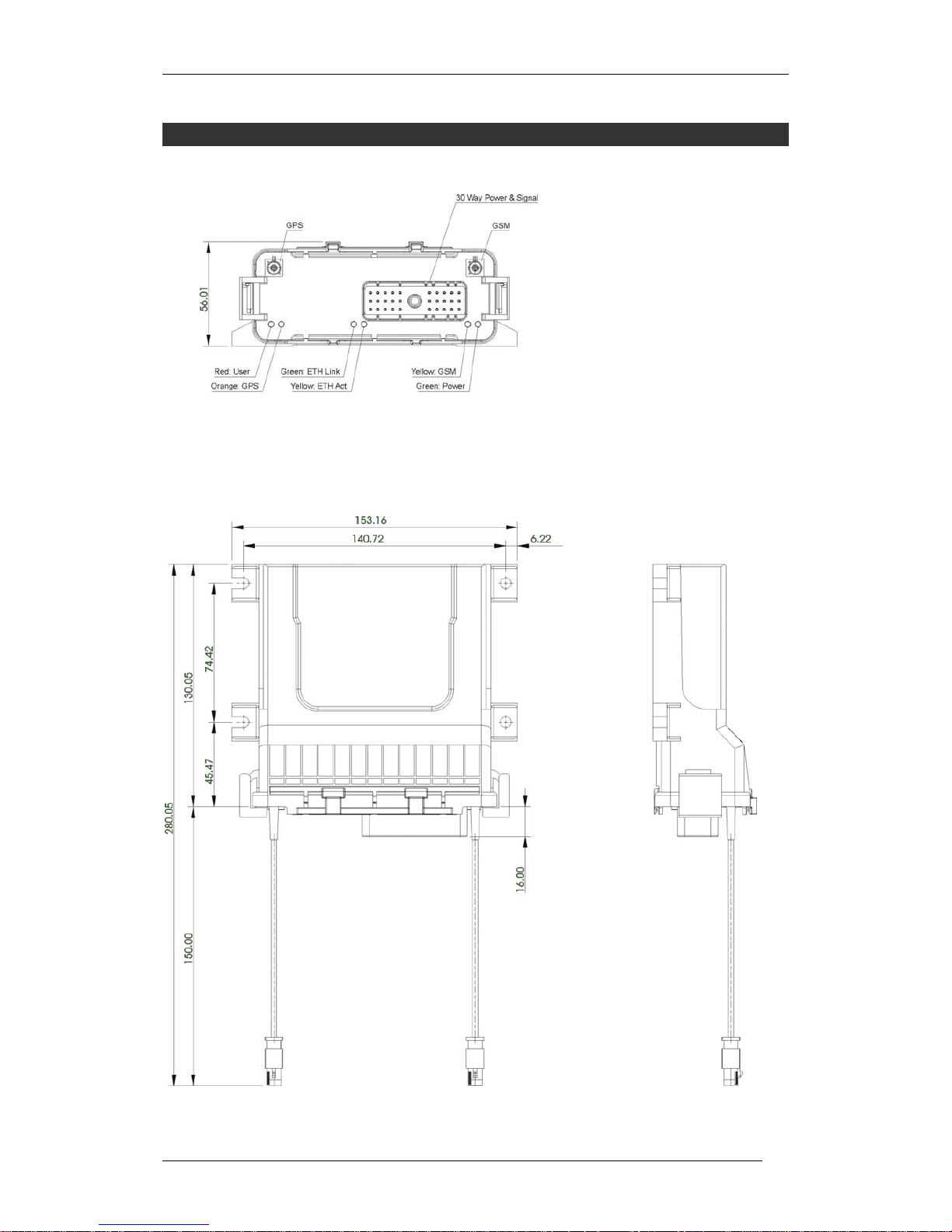
Figure 4.1.1 owa23X Physical description
Page 21
owa23X Platform Integrator’s Manual
BOK-100 1065-C-owa23X Platform Integrator's Manual
15
Note that the central LEDs (ETH link and ETH activity) are only available on
units with the Ethernet option.
4.2 Hardware Features
4.2.1 Microprocessor and Memory
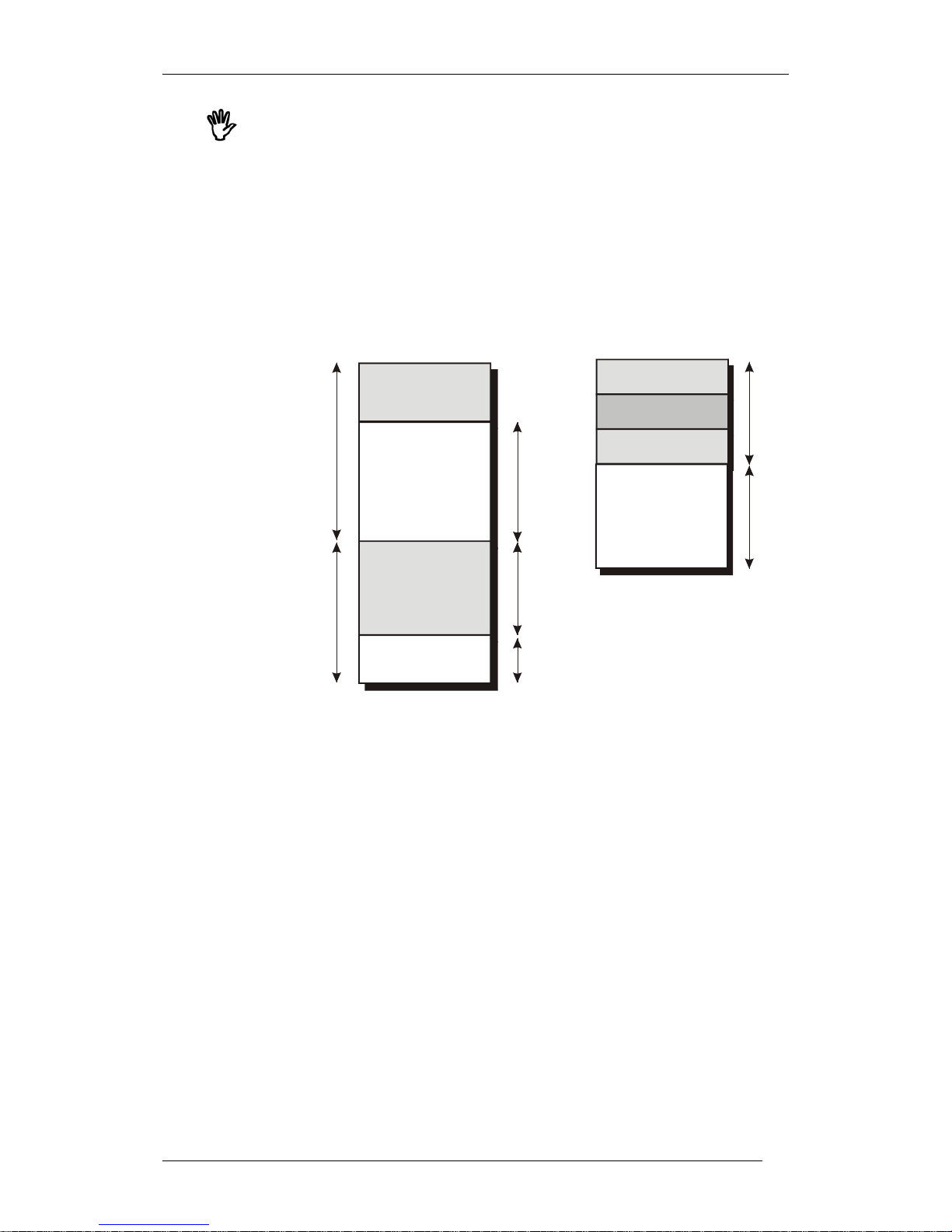
32 bits RISC ARM7 core up to approximately 60 MIPs at 70 MHz with 16 Mbytes
of volatile RAM and 8 Mbyte of non-volatile FLASH. These provide, in terms of
available user space, 6.5 Mbyte free RAM and 4 Mbyte free Flash. Memories are
arranged as shown below.
BOOT
KERNEL
8 MB FLASH
4 MB
4 MB
FREE SPACE
FILESYSTEM
SYSTEM USED
FREE SPACE
10 MB
16 MB RAM
6.5 MB
4 MB
2 MB
RAMDISK
6 MB
FREE SPACE
OWASYS FILE
SYSTEM
Figure 4.2.1.1Memory arrangement.
The RAM memory is divided into two different areas:
A RAM disk with 6 MB available: 4 MB for the owa2x file system and 2 MB
available for temporary files.
10 MB shared by system and user applications; initially 6,5 MB are
available for user applications.
The FLASH memory is divided in two different areas:
owa2x firmware: boot loader, kernel and file system. It takes 4 MB
approximately.
user space: 4MB physical flash space. Not 100% of this is available as user
space. Refer to chapter 11 of the Programming Guide [1] about Flash
memory use recommendations.
4.2.2 GSM/GPRS System
owa23X provides GSM communication (Quad band EGSM 850-900-1800-1900 is
supported depending on the Cellular Infrastructure and on used Operators).
Audio calls, data calls and Short Message Service are the features supported by
GSM.
Page 22
owa23X Platform Integrator’s Manual
BOK-100 1065-C-owa23X Platform Integrator's Manual
16
GPRS is a widely deployed value added service of the cellular infrastructure
that enables direct access to public and private data networks (Internet,
corporate networks, private networks...). Using the owa23X
GPRS service
instead of simple GSM service significantly reduces traffic cost since resources
are only allocated when data is to be sent/received.
GPRS service is type B and class 10 (4+2). Four time-slots for the downlink and
two for the uplink are available.
GSM-GPRS modem supports multiplexed communication allowing GSM events,
USSD´s and sending/receiving SMS´s during GPRS connections.
4.2.2.1 GSM Antenna
Connector t
yp
e FAKRA plug (bordeaux)
Mating connector FAKRA jack (bordeaux)
Table 4.2.2.1.1 GSM antenna connector
4.2.3 GPS
GPS functionality is included in the owa23A models.
GPS (Global Positioning System) is a system composed of a constellation of
satellites orbiting the Earth, transmitting signals that allow the GPS receivers
to determine the receiver position (longitude, latitude and height) and time
(Universal Time Coordinated, UTC).
With the GPS included in owa23A, accurate position and time information is
provided for Location Based Applications. The default datum used by the GPS is
WGS-84.
The GPS can work in 2D navigation (viewing 3 satellites) or 3D navigation
(viewing at least 4 satellites). When the GPS starts up, it gives a valid position as
soon as it sees 3 satellites, but it can only know the altitude when it sees 4
satellites. This is the reason why in the starting process, there is the possibility
of a position jump. This position jump is more likely to happen the greater the
altitude is.
The GPS outputs the altitude as HAE (“Height Above Ellipsoid”) (i.e. WGS-84).
But since an ellipsoid cannot model the shape of the earth perfectly, one sees
some deviation from the so-called “Mean Sea Level” altitude. MSL refers to the
actual sea level. The difference between these two altitudes can exceed 100m.
The GPS data are backed-up for at least 2 hours. GPS data older than 2 hours is
no longer valid and a cold start will be performed. The GPS backup battery
requires powering the owa23X for at least 14 hours to reach a complete charge.
The GPS receiver is the ANTARIS technology from ublox.
4.2.3.1 GPS Antenna
owa23A products have a built-in GPS module. Use only external GPS active
antenna connected to the GPS connector provided in the rear panel.
Connector type FAKRA plug (blue)
Mating connector FAKRA jack (blue)
Table 4.2.3.11 GPS antenna connector
Page 23
owa23X Platform Integrator’s Manual
BOK-100 1065-C-owa23X Platform Integrator's Manual
17
By means of internal circuitry, the owa23A is able to detect if the GPS antenna
is operating correctly, or if there is an open circuit or a short circuit. See
section 6 for a detailed specification of GPS antenna.
4.2.4 30 Pin Multipurpose Connector
The owa23x includes a 30 pin connector where all signals (except GPS and
GSM) are availble. This is power supply, RS232, RS485, CAN, General Purpose
I/Os, ADINs and Audio or Ethernet signals (depending on option).
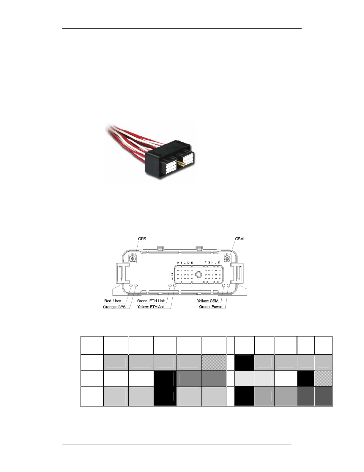
The owa23X is provided with the mating connector and cable, as shown in the
following diagram.
Figure 4.2.1.1 . 30 Pin Mating Connector with cable.
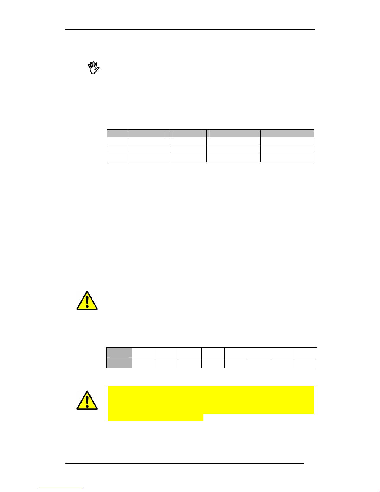
30-pin connector pin out is as follows. This table corresponds to the pin-out as
seen looking at the owa23X box. The colours correspond to the wire colours
provided in the supplied loom.
Figure 4.2.1.2 . 30 Pin Connector pin functions.
Column
Row
A B C D E F G H J K
1
I/O-7 I/O-6 I/O-5 I/0-4
VOUT
GNDISO
I/0-3 I/0-2 I/O-1 I/O-0
2
CAN0H CAN0L
GNDISO
RS485A RS485B
ADIN1 ADIN0 ON/OFF GND
VIN
3
MICP
ETH-RX+
MICN
ETH-RX-
GND
SPKP
ETH-TX+
SPKN
ETH-TX-
GND
RTS0 CTS0 RX0 TX0
Table 4.2.4.1 30 Pin connector pin functions
Page 24
owa23X Platform Integrator’s Manual
BOK-100 1065-C-owa23X Platform Integrator's Manual
18
More detailed information is despicted in the following chapters. Pins are
referred as column-row identification, e.g Vin = K2.
Note that pins A3, B3, D3 & E3 function as the Audio or Ethernet interface
depending on model. Also pins A2 & B2 provide CAN connection when available.
See section 2.3.
4.2.5 Power Supply
Power supply in the 30 pin connector is used to supply power to owa23X.
Signals used for this purpose are:
Pin Signal Type Min level Max level
K2 Vin Power in 6.0V 40.0V
J2 GND Ground - H2 ON/OFF Input OFF = 0 to 0.5V ON = Leave OPEN
Table 4.2.5.1 Power supply connector pins function
Vin and GND should be connected to a clean, stable supply between 6.0 and
40.0 Vdc. A cable with a current rating of more than 5A should be used.
Max supply current is 1.5A @ 6V, 0.8A @ 12V or 0.4A @ 24V. For typical supply
currents under various operating conditions see 4.4 Power Management.
The power supply can be made with a battery or continuous voltage supply with
reinforced isolation, and limited in power to a maximum of 8A and 100 VA.
ON/OFF: Power Control Input signal. Leave open for ON, Connect to ground for
OFF. Use an open collector transistor or switch to ground, but do not drive high.
This input will turn the unit ON or OFF. When running from battery back-up,
this signal can only be used to turn the unit OFF. If the signal is then released
and there is no power on Vin, then the unit will remain OFF.
4.2.6 Fusing
The owa23X does not include internal fusing. An external fuse should be
included in the positive Vin supply with a rating of 5A to protect the cables and
input circuitry in case of a fault condition.
4.2.7 Digital Inputs/Outpus
8 configurable Digitel Input/Outputs are provided for the owa23x family, as
follows:
PIN A1 B1 C1 D1 G1 H1 J1 K1
Signal I/O-7 I/O-6 I/O-5 I/O-4 I/O-3 I/O-2 I/O-1 I/O-0
Table 4.2.5.1 Digital I/O pin out
These pins can be configured as inputs or as outputs. Note that if the pin is
configured as an output it cannot be used as an input, and may be damaged if a
voltage is applied while it is configured as an output. Hence ensure that the
corresponding output pin is OFF before using it as an input. See the
programming guide for more details.
The digital inputs are compatible with normal TTL logic levels, but can also
withstand inputs up to 40V so that sensors and switches with higher voltages
can be used. For example, in an automotive application, a switch may be
Page 25
owa23X Platform Integrator’s Manual
BOK-100 1065-C-owa23X Platform Integrator's Manual
19
connected to the positive supply giving an input of 14V or 28V. The input
impedance is 100 kΩ.
The Digital I/Os have the following ranges and levels:
Signal Type Low level High level
I/O-0..7 Output 0.5V @ 100mA sink Max 40.0V
I/O-0..7 Input 0-0.7V 2 to 40V
Table 4.2.5.1 Digital I/O signal levels
If the digital output is set to 0 in the software it will be OFF and the transistor
will pull the output pin to ground giving a low level. Note that there are no pullups on these pins so to obtain a high level when the output is ON requires an
external pull-up to a positive supply.
The outputs are open collector transistor type capable of switching up to 40V
and sinking up to 100mA. Do not place a load that will draw more than 100mA
or damage to the unit may result.
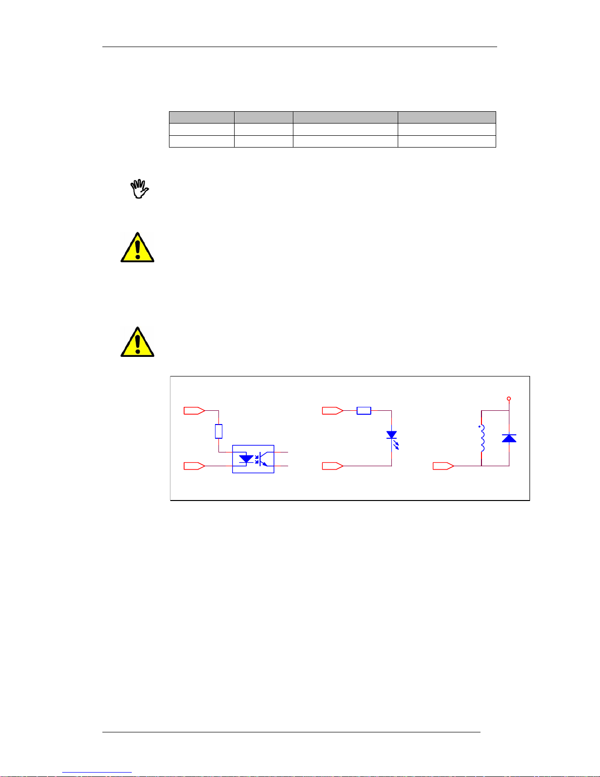
The load should be connected between the output pin and a positive supply. The
positive supply could be provided by the user, or from the pin Vout (E1). The
maximum output current from Vout is 100mA, which should be sufficient to
drive up to 8 LEDs, Opto-couplers or Solid State Relays at 10-12mA each. A
typical connection for one output is shown below.
For an inductive load (such as a relay or motor) it is recommended to connect a
free-wheeling diode to provide a return path to the supply for the inductive
energy, as shown below. Otherwise the resulting voltage spikes during switch
off could damage the output circuitry.
OUT0..3
Vout
DIGITA L OUTPUT TYPICAL LOA DS
OPTO-COUPLER LOAD
1
2 3
4
OUT0..3
Vout
330R
1 2
OUT0..3
V_USER
I LED = 10mA Approx . I LED = 10m A Approx .
330R
12
LED LOAD
LED
12
A C
IN D U C TIVE LOAD W I TH
FR EE-W H EELI N G D I OD E
Figure 4.2.7.2 Digital output typical loads
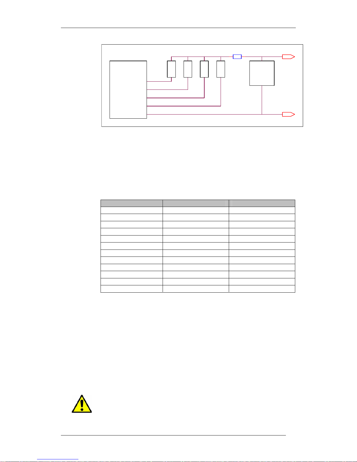
If loads with higher power are required, the user can connect a separate power
supply as shown below. In the following example, each load can be up to
100mA, giving a total fuse current of 800mA. The fuse should be fast blow type.
Page 26
owa23X Platform Integrator’s Manual
BOK-100 1065-C-owa23X Platform Integrator's Manual
20
Figure 4.2.7.3 Driving loads from user supply
To maintain backward compatibility with applications developed for the owa21X
and owa22X platforms, the following I/O mapping can be used:
owa21X owa22X owa23X
IN0 IN-0
IN1 IN-1
IN2 IN-2
IN3 IN-3
OUT0 OUT-0
OUT1 OUT-1
OUT2 OUT-2
OUT3 OUT-3
IGNITION IGNITION IN-4
CONTACT CONTACT IN-5
LIGHTS / ODOMETER LIGHTS IN-6
MUTE MUTE OUT-7
Table 4.2.5.2 Cross Platform I/O signal mapping
4.2.8 Odometer / Counter
Input IN-6 (pin B1) is provided to connect an odometer sensor for measuring
distance, or general pulse counting. The input accepts digital output sensors
with an output voltage greater than 5V
P-P
. The signal adds up in a HW register
that can be accesed at any time, and an interruption can be configured and
enabled to interrupt the CPU at a programmable ratio. The user application can
then use this interrupt to implement odometer / counter functions as required.
See the Programming Guide [1] for more information.
4.2.9 Vout Power Output
The owa23X provides a regulated 4.5V power output for accessories or user
loads. The maximum output current from Vout is 100mA. Do not exceed this, or
damage to the output circuitry may result.
DRIVING LOADS FROM USER SUPPLY
LOAD
LOAD
LOAD
LOAD
USER
PSU
3-40V
FUSE
400mA
1 2
GND
OTHER
USER
LOADS
OUT0
OUT1
OUT3
GND
owa2X
OUT2
Page 27
owa23X Platform Integrator’s Manual
BOK-100 1065-C-owa23X Platform Integrator's Manual
21
4.2.10 Analog Inputs
The owa23X provides 2 external and 3 internal analog inputs, as follows:
ADC Use Range Accuracy Impedance
ADIN0 External pin G2 0-5.45V ±2% 2MΩ
ADIN1 External pin F2 0-5.45V ±2% 2MΩ
ADIN2 Internal Vin 0-30.8V ±2% ADIN37 Internal VBAT 0-5.45V ±2% ADIN4 Internal temperature -40 to +85ºC ±5ºC -
Table 4.2.5.1 Analog Inputs
A software API is provided to read these ADC values. See ref [2]
owa2X Family
Programming Reference Manual.
4.2.10.1 Scaling Input Range
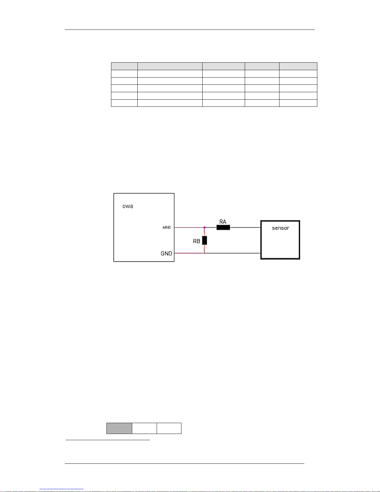
The allowed voltage range in owa23X is 0-5.0V, which may not match with the
majority of sensors available in the market. It is quite easy to build a passive
matching network that allows those sensors to be connected to owa23X. See
figure below (use always resistors of 1% precission)
Figure 4.2.12.1 Adapting sensors to Analog Inputs
For current output sensors (4...20 mA), use RA = 0Ω and RB = 250Ω. If 250Ω is
not available then 4 x 1kΩ in parallel can be used. This will convert the full
scale 20mA into 5.0V
For sensors with output voltage greater than 5.0V, choose RB << 200kΩ and
following relationship between resistors:
RA = RB (Vsensor – 5)/5
Use always resistors of at least 1% precission. Calculated resistor values
should fall into the standard EIA values depending in tolerances (EIA E96 for 1%
tolerance), otherwise you should take a neighbouring value at the expense of an
additional error.
As an example, for a 12 V sensor output, consider RB = 1kΩ, then RA = 1.4kΩ,
which are standard E96 values.
4.2.11 CAN
The owa23X includes a CAN transceiver that support ISO 11898 Transport level.
This bus is high speed, up to 1 Mbaud.
PIN A2 B2
7
ADIN3 is provided to measure the voltage of the optional high capacity battery in the owa23X/b units.
Page 28
owa23X Platform Integrator’s Manual
BOK-100 1065-C-owa23X Platform Integrator's Manual
22
Signal CAN0H CAN0L
Table 4.2.5.1 CAN pin out
The internal controller in owa23X supports CAN protocol version 2.0 part A and
part B (‘extended format’ 29 bits) regarding to the data link layer. For more
detailed information see
owa2X Family Programming Guide.
CAN transceiver can be put in low power mode when it is not used.
First and last devices in the CAN bus should be equipped with terminating
resistors of 120 ohms. Owa23X does not have this terminating resistor
internally so it must be added externally.
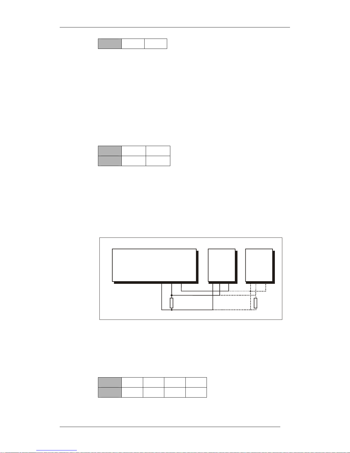
4.2.12 RS485
The owa23X provides an RS485 bus driver connected to UART1 on the CPU.
PIN D2 E2
Signal RS485A RS485B
Table 4.2.5.1 RS485 pin out
This is a half duplex interface whose maximum speed can be 115200 baud. The
number of devices that can be connected in parallel to this interface is 32.
In the following diagram an example of a set of devices connected to the owa2x
through a RS485 bus is shown.
First and last devices in the bus should be equipped with terminating resistors
of 120 ohms. Owa23X does not have this terminating resistor internally so it
must be added externally as depicted in next figure.
RS484-A
120
owa22x connected through RS485 bus to other RS485 devices
120
AB
GND
AB
GND
owa22x
RS485
device 1
RS485
device N
RS484-B
RS484-GND
Figure 4.2.12.1 owa23X RS485 bus
4.2.13 RS232
The owa23X provides an RS232 bus driver connected to UART0 on the CPU.
PIN G3 H3 J3 K3
Signal RTS CTS Rx Tx
Table 4.2.5.1 RS232 pin out
Page 29
owa23X Platform Integrator’s Manual
BOK-100 1065-C-owa23X Platform Integrator's Manual
23
This is a standard RS232 interface with corresponding voltage levels, whose
maximum speed can be 115200 baud. Only TX, RX, RTS and CTS are provided.
Flow control pins DTR, DCD and DSR are not provided.
4.2.14 Ground
Caution: the ground pins in the multipurpose connector are internally
connected to the ground of the RF antennas. To avoid excessive ground current,
ensure that they are not connected to different grounds points in the
installation.
4.2.15 Audio
An audio interface is provided (depending on model, see section 2.3) with
separate connection for speaker and microphone. Together with built-in echo
cancellation features, it allows owa23X devices to easily enable hands-free
functionality. All that is needed is to connect an external microphone and an
amplified speaker.
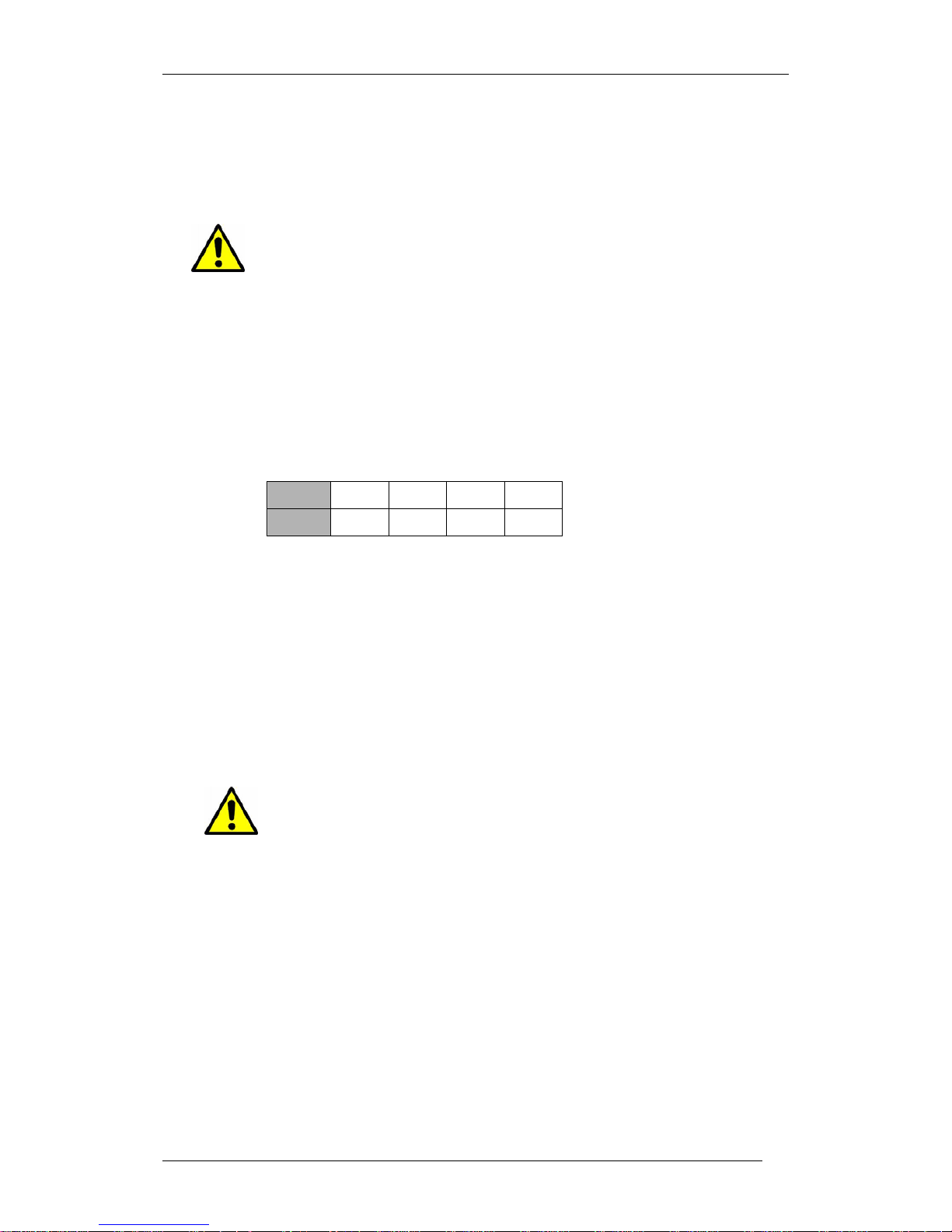
PIN A3 B3 D3 E3
Signal MICP MICN SPKP SPKN
Table 4.2.5.1 Audio pin out
4.2.15.1 Speaker Outputs SPK
Audio output is of BTL type (Bridge Tied Load), so none of the speaker signals
are internally connected to ground. This kind of connection is used to avoid
radio frequency noise interference with audio signals.
If signal is to be used in single ended mode, use a minimum load of 200 kΩ
between either SPK signal and GND.
Maximum allowed Capacitance in differential mode is 100 pF.
Maximum Inductive load is 47nH @ 200 MHz
Never connect any terminal of the speaker output directly to ground or power
supply as it may damage either the speaker or the owa23X.
The recommended external speaker has the following features:
Impedance higher than 8 Ω.
Frequency response 300 Hz - 3,4 kHz (recommended)
4.2.15.2 Microphone Inputs MIC
Microphone input is of balanced type (signal is not referred to ground) and
accepts electret type microphones. Those are the type of microphones most
widely used for consumer purposes. They need a clean, very stable power
supply (usually called V
BIAS) that is provided by owa23X. Signal Input MICP and
V
BIAS share the same pin in the connector, as this is the connection usually
found in commercially available microphones.
Microphone sensitivity is usually expressed in terms of voltage/acoustic
pressure (dB/μPa.). Higher value means best sensitivity, so a microphone rated
at -46 dB/μPa is worst than another at -36 dB/μPa.
Page 30
owa23X Platform Integrator’s Manual
BOK-100 1065-C-owa23X Platform Integrator's Manual
24
The recommended features of the microphone are:
Use only electret type microphones
High sensitivity is recommended for hands free applications (in the
range of -46 dB/μPa).
Impedance equal or higher than 1 kΩ.
Signal and BIAS tied together (2.5 V).
Power consumption less than 1 mA.
4.2.16 Ethernet 10-BaseT
The owa23X-ETH includes an ethernet 10-BaseT connection, with pin-out as
follows. Note that these pins should be connected to a twisted pair CAT5 type
cable to enable correct functioning of the Ethernet at full speed and to reduce
EMI.
PIN A3 B3 D3 E3
Signal ETH-RX+ ETH-RX- ETH-TX+ ETH-TX-
Table 4.2.5.1 Ethernet pin out
Ethernet activity is indicated by means of the two leds. Refer to chapter 4.1 to
identify them.
owa21I-ETH State Yellow LED
OFF OFF
Ethernet Activity ON (Blinking)
Table 4.2.16.1 owa21I-ETH: Yellow LED indications
owa21I-ETH State Green LED
OFF OFF
Link OK ON
Table 4.2.16.2 owa21I-ETH: Green LED indications
4.2.17 LEDs
Four LEDs are provided on the front panel. Refer to chapter 4.1 to identify them.
The green LED on owa23X shows the current functional state, according to the
table below. By default, the Green LED is ON, but the user can change the state
of this LED so that it follows its own state code. For more information about the
control of the Green LED, see
owa21X Family Programming Guide.
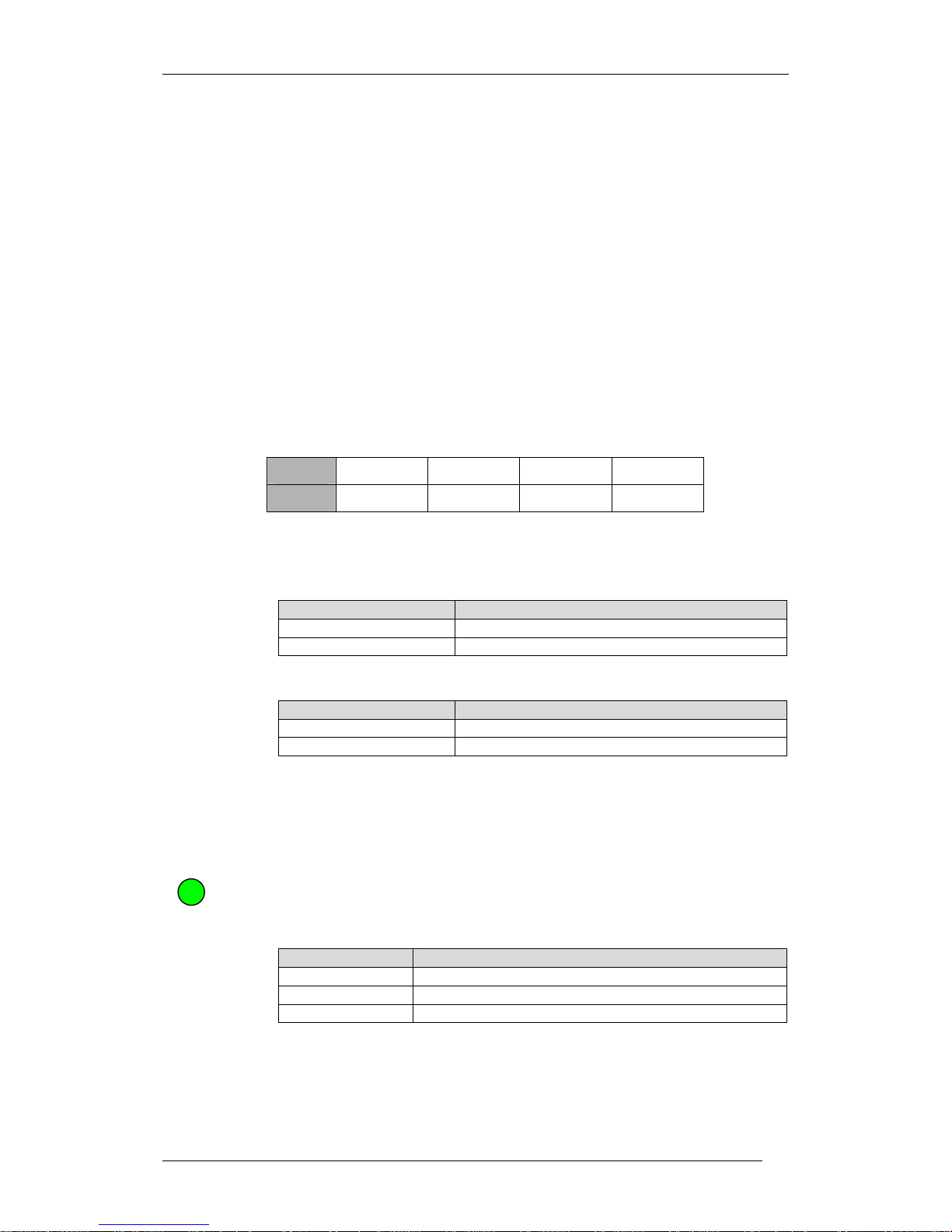
owa23X State Green LED
OFF OFF
Service Mode ON (Blinking when downloading owa23X firmware)
Operation Mode Configurable
Table 4.2.17.1 owa23X Green LED indications
Page 31
owa23X Platform Integrator’s Manual
BOK-100 1065-C-owa23X Platform Integrator's Manual
25
The yellow LED is used to indicate the status of the GSM Module as shown in
the table below:
GSM Module State Yellow LED
OFF Off
ON without cellular coverage On
ON with cellular coverage Blinking
Table 4.2.172 owa23X Yellow LED indications
The yellow LED is lit as soon as the device is switched ON since the GSM
module is powered on. If a SIM card without PIN is inserted in this device, the
GSM module attaches to the network automatically although the user
application did not call to GSM_Initialize and GSM_Start.
This yellow LED may be configured by the user to follow its own state code.
However, the user must enable it explicitly first, as by default is controlled by
the GSM module.
The orange LED on owa23X is controlled by the GPS module and gives one
pulse per second when the GPS module has coverage.
GPS Module State Orange LED
OFF Off
ON without coverage Off
ON with coverage One pulse per second
Table 4.2.17.3 owa23X Orange LED indications
The orange LED may also be configured by the user to follow its own state code.
However, the user must enable it explicitly first, as by default is controlled by
the GPS module.
The red LED on owa23X is user programmable. For more information about the
control of the Red LED, see
owa23X Family Programming Guide.
Two additional LEDs are provided on the owa23X-ETH models, and are
described in chapter 4.2.16.
4.2.18 SIM Card Holder
The SIM Card Holder provided is for the GSM/GPRS service. Only 3V SIMs are
supported. For inserting the SIM card in the holder see section 5.1
4.2.19 Battery Back-up
The owa23X is provided with a small dedicated internal battery for RTC and GPS
data retention. In addition to this it is possible to install a high capacity battery
to allow continuous operation of the owa23X without external power. Units that
have this option fitted in the factory have the “/b” suffix.
4.2.19.1 RTC and GPS Data Battery
This is a small dedicated battery which is supplied with all owa23X units to
provide backup of the RTC and GPS data. The RTC will be maintained for a
minimum of one month. The GPS data is only maintained for 2 hours as after
Page 32
owa23X Platform Integrator’s Manual
BOK-100 1065-C-owa23X Platform Integrator's Manual
26
this time it is no longer valid. The Power Management Unit also runs from this
battery in Zero Power Mode (see section 4.4.1.4).
The owa23X should be powered for at least 14 hours to allow complete charge
of this battery.
4.2.19.2 Optional High Capacity Battery
An optional high capacity battery back-up can be installed (POP 100 2100),
which allows continuous operation when the main power is lost. This enables
the owa23X/b
to e.g. make a final call before going into low power mode, or a
similar procedure, as defined by the customer application software.
If the battery back-up is not pre-installed inside the unit, then use the following
procedure to install it.
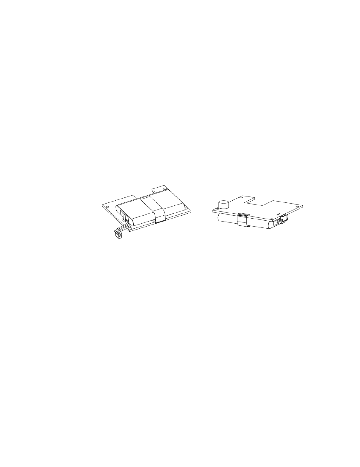
Before proceeding to install the battery pack, prepare the connecting cable as
shown in the figure below. That is, bend the cable to the left side and down.
Then stick the poron pad (supplied with your battery) as shown in the figure.
This is on the opposite face from the battery pack, and close to the mounting
hole (exact position is not critical).
Figure 4.2.19.2.1 Battery back-up
First open the front cover as shown in section 5.1, following the indicated
moisture precautions.
The main board and battery are ESD sensitive, so use appropriate precautions.
Mount the battery with the provided screws and mounting posts. Plug in the
four-pin connector from the battery to the four-pin connector placed on the
main board.
Page 33
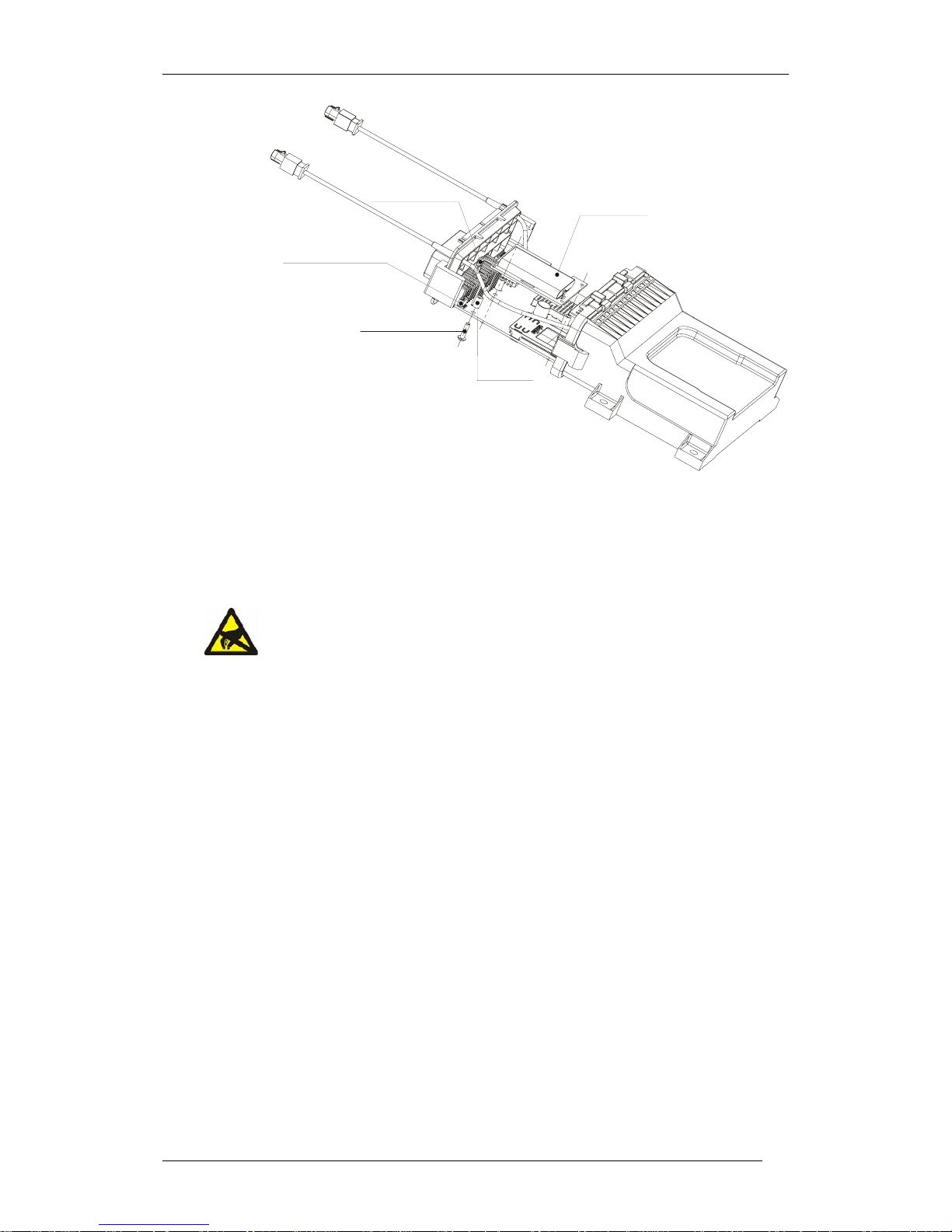
owa23X Platform Integrator’s Manual
BOK-100 1065-C-owa23X Platform Integrator's Manual
27
BATTERY PACK
MES 100 2100
SCREW (x3)
Torq-Set : 40 cN.m
SCR 100 3013
SCR 100 3002
SPACER (x3)
Battery Pack Connector
PCB Battery Pack Connector
Figure 4.2.19.2.2 Battery back-up installation.
NOTE: Do not use a conducting object such a screwdriver to push in the
connector, at this might short the contacts on the connector. Also take care to
not touch the other internal components.
At this stage the SIM card may also be installed.
Close the front cover ensuring all catches have closed.
Once the battery has been installed, it may be necessary to turn off the owa23X.
This can be achieved by grounding the ON/OFF signal in the Power Supply
Connector (see section 4.2.4) for several seconds. This can be done by
connecting pins H2 and J2 in the main connector.
When the owa23X/b is first installed, or after operating from battery backup, or
after a long period without use, the unit should be powered for at least 12 hours
to allow full battery charge. Do this by connecting the unit to an appropriate
power source (6-40VDC). As the battery does not suffer ‘memory effect’, a full
discharge is not required.
The battery backup allows emergency calls if the main power supply is lost and
also standby applications where the unit could be in Zero Power Mode for
extended periods of time and wake up occasionally to take a measurement and
send a message.
When the unit is fitted with the internal battery it may be turned OFF by
grounding the ON/OFF pin in the Power Supply Connector (see section 4.2.4).
However it can only be turned ON again by applying power to Vin on the Power
Supply Connector. This enables the unit to be stored in the OFF condition.
The battery is a Li-Ion 3.7 V cell with minimum of 1000mAh. See Table 6.7 for
the duration of the battery in the various modes of operation.
Page 34

owa23X Platform Integrator’s Manual
BOK-100 1065-C-owa23X Platform Integrator's Manual
28
The battery will only be charged at temperatures between 0ºC and +45ºC. An
internal circuit disables charging when outside the limits.
The useful discharge temperature range is between -20ºC and +60ºC. Battery
capacity is greatly reduced at low temperatures. At -20ºC only approximately
30% of the capacity is available.
4.2.20 Internal Temperature
The owa23X has a sensor to measure its internal temperature.
The sensor could be used, for example, to shut down the GSM module when it
is outside the specified operating range of -20 to 70ºC.
This temperature sensor cannot be used to measure external environment
temperature due to the difference between this temperature and the owa23X
internal temperature.
For more information about the APIs, see ref [2]
owa2X Family Programming
Reference Manual
.
The temperature sensor is connected to ADIN4. See section 4.2.10 for further
details.
Temperature range: -40ºC to +85ºC
Accuracy: ±5ºC
4.2.21 System Time
The owa23X unit is provided with two different clocks:
The CPU system time: This clock is able to maintain system time in
normal operation but loses the time when owa23X is powered off, or
enters power save modes.
The RTC module: This is a dedicated Real Time Clock (RTC) module
which is battery backed up so that the time remains correct even
when power is removed.
RTC time is always up to date provided power supply is applied to the owa23X.
If power supply is removed or the owa23X turned OFF or is in ZERO POWER
mode, an internal battery is keeps the time for a minimum of 1 month.
When the owa23X returns from OFF or from any of the power save modes
(SLEEP, LOW POWER, ZERO POWER), the CPU system time is automatically
updated with the value in the RTC time. Hence any changes to the time should
be performed on the RTC time as this is the ‘master’.
owa23X/b versions with optional high capacity backup can maintain the internal
RTC time for as long as the duration of the high capacity battery. Refer to
chapter 4.4.2 for the duration in the various modes.
owa23AX models have an additional and more precise time reference that is
obtained from GPS data. When available, use this as a reference to set the RTC
value.
4.2.22 Watchdog
A hardware watchdog module is initialized every time the system scheduler
starts. If the watchdog detects that the scheduler is not running for a while, it
restarts the system automatically.
This watchdog does not by any means protect against user application being
blocked or not responding. The user is responsible to implement an application
Page 35

owa23X Platform Integrator’s Manual
BOK-100 1065-C-owa23X Platform Integrator's Manual
29
level watchdog. For a detailed description of the several watchdog levels
available see corresponding chapter in ref [1]: Programming Guide Manual.
4.2.23 Protection
4.2.23.1 Transient Protection
To protect the Power Supply Unit from transients greater than the normal input
range, a transient voltage suppressor is fitted between Vin and GND.
4.2.23.2 Polarity Reversal
If the user interchanges GND and Vin, an internal diode avoids internal circuitry
damage.
4.2.23.3 Electrical Interference
To avoid electrical interference owa23X includes an EMI filter in the input power
circuitry.
4.2.23.4 Fusing
The owa23X does not include internal fusing. An external fuse should be
included in the positive Vin supply with a rating of 5A to protect the cables and
input circuitry in case of a fault condition.
4.2.24 Movement Sensor
The owa23X includes a movement sensor so that the unit can respond to
situations where the vehicle or goods are being moved. This is particularly
useful for anti-theft and asset tracking applications, where the owa23X can be
in Low power or Zero Power mode for extended periods, and only wake up
when there is a movement.
The sensor detects any vibrations in any direction.
Page 36

owa23X Platform Integrator’s Manual
BOK-100 1065-C-owa23X Platform Integrator's Manual
30
4.3 Functional States
The owa23X can work in one of the following functional states
State Description
OFF owa23X is switched off
SERVICE
The operating system is running but there is no customer
application installed. The owa23X is prepared to receive
system commands
From this state, it is possible to download files and/or
firmware into owa23X
OPERATION
The customer application is running in either RUN mode,
SLEEP mode, LOW POWER mode or ZERO POWER mode (see
section 4.4).
Table 4.3.1 owa23X Functional states
Figure 4.3.1 Functional states.
Once the owa23X is switched on, it starts executing the boot loader, (see section
4.5.1.1). Then, if the developer stops the process, the owa23X will remain in
Service state. Otherwise the owa23X continues loading the kernel and the file
system.
When there is no customer application within the
userinit.sh
file, owa23X will
remain in Service state. In this situation, after entering the login, owa23X is
waiting for commands under Linux.
However, if there is a customer application stored within
userinit.sh
file,
owa23X will enter the Operation state, and start in the Run mode. For further
information see section 4.4 Power Management.
4.4 Power Management
The owa23X platform has been designed to optimise power consumption. To
take full advantage of this, several power modes have been provided to give the
user full control of the platform power consumption. The owa23X has a
OFF
OPERATION
SERVICE
Page 37

owa23X Platform Integrator’s Manual
BOK-100 1065-C-owa23X Platform Integrator's Manual
31
dedicated Power Management Unit that can shut down the main CPU and other
circuitry to minimise consumption. The Power Management Unit also contains
the RTC and hardware watchdog. Control of the Power Management Unit is via
the power management API. See the Programming Guide [1]. Hence the user
application can select the appropriate power mode depending on power
consumption requirements. A simple demonstration of the power management,
RTC, odometer and movement sensor functions can be found in owa23X-AN8.
4.4.1 Power Modes
A description of the various power modes available is described in the following
chapters.
4.4.1.1 Run Mode
The CPU is on and running at full speed. This is the normal mode when
executing application code. Power consumption within this mode can be
optimised by closing down the GSM and GPS modules.
4.4.1.2 Sleep Mode
The CPU is powered on but stopped (as per deepsleep in the owa22X platform).
The advantage of this mode is that code execution begins immediately after
exiting this mode, whereas in the Low Power and Zero Power modes the
application will not resume until the boot has been completed.
Depending on the user application the GSM and GPS modules can be either ON
or OFF in this mode.
This mode can be exited with the following signals:
IN-2, 4, 5 & 6
PSU_fail
Moved
RTC
UART0 (RS232)
UART1 (RS485)
GSM
Note that a GSM event will
always
result in a wake up from SLEEP mode. This
is to ensure that all GSM events are serviced by the CPU.
4.4.1.3 Low Power Mode
To reduce power, the CPU is turned OFF. Note that when exiting from this mode
a system boot will occur which takes approximately 20 seconds. Hence this
mode should only be used for longer time periods (e.g. wake up once every 5
minutes or more), and where a quick response to an event is not required.
Depending on the user application the GSM module can be either ON or OFF in
this mode. The GPS module is OFF by default.
This mode can be exited with the following signals:
IN-2, 4, 5 & 6
PSU_fail
Moved
Page 38
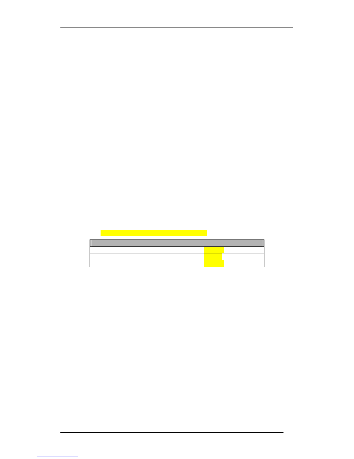
owa23X Platform Integrator’s Manual
BOK-100 1065-C-owa23X Platform Integrator's Manual
32
RTC
GSM
4.4.1.4 Zero Power Mode
In this mode all circuits (GSM, GPS, CPU, etc.) are shut down and the Power
Management Unit is running from the dedicated internal battery (see section
4.2.19.1). The duration of this battery depends on the wake up signals as shown
in table 4.4.1.4. The user application should ensure that this mode is exited
periodically to enable recharge of the dedicated internal battery. For example,
if the RTC is being used as the exit signal, then the application should change to
Low Power, Sleep or Run modes for a minimum of one day per month to allow
recharging. See table 4.4.1.4.
Note that when exiting this mode a system boot will occur which will take
approximately 20 seconds. Hence this mode should only be used for longer
time periods (e.g. wake up once every 5 minutes or more), and where a quick
response to an event is not required.
This mode can be exited with the following signals:
• IN-2, 4, 5 & 6
Moved
RTC
The odometer counter is running from the dedicated internal battery in this
mode. At higher frequencies the consumption increases. If the odometer
counter is to be used at high frequencies, then it is recommended to use Low
Power Mode.
NOTE: Preliminary values. To Be Confirmed.
Wake up signal Typical Duration @ 25ºC
IN-2, 4 5 & 6 or Moved or RTC 1 month
Odometer @ 3 kHz 8 hours
Odometer @ 1 Hz 1 month
Table 4.4.1.4 Dedicated internal battery duration
The following diagram summarises the operation modes.
Page 39
owa23X Platform Integrator’s Manual
BOK-100 1065-C-owa23X Platform Integrator's Manual
33
RUN
(CPU ON)
SLEEP
(CPU sleep)
LOW POWER
(CPU OFF)
ZERO POWER
Function:
EnterSleep
Function:
EnterLowPower
Function:
EnterZeroPower
Exit conditions:
• IN-2, 4, 5 & 6
• PSU_fail
• Moved
• RTC
• UART0 (RS232)
• UART1 (RS485)
• GSM
Exit conditions:
• IN-2, 4, 5 & 6
• PSU_fail
• Moved
• RTC
• GSM
Exit conditions:
• IN-2, 4, 5 & 6
• Moved
• RTC
Page 40
owa23X Platform Integrator’s Manual
BOK-100 1065-C-owa23X Platform Integrator's Manual
34
4.4.2 Power Consumption
The following table gives the typical average power consumption in the
previously described modes. Note that the values given with GSM or GPS
running will vary depending on signal strength and network conditions.
The first three columns show the input current for the unit running from
external power on V
IN
. The last column shows the duration for the unit running
from the optional high capacity battery in the owa23X/b.
Note that the duration values are for indication only. It is recommended to run
tests with the final customer application to determine actual durations. The
duration assumes a fully charged battery and is for an operating temperature
of 25ºC. The duration will be greatly reduced at low temperatures. For
example, at -20ºC the duration will be approximately 30% of the shown values.
NOTE: Preliminary values. To Be Confirmed.
Power Source External Power VIN Optional Battery
Mode IIN @ 6V IIN @ 12V IIN @ 24V Duration
Run (GSM, GPS on) 1 360 mA 180 mA 95 mA 2 hours
Run (GSM, GPS off) 2 65 mA 35 mA 19 mA 12 hours
Sleep (GSM on network) 3 11 mA 6 mA 4.5 mA 3 days
Sleep (GSM off) 4 7 mA 4 mA 2.5 mA 5 days
Low Power (GSM on network) 5 7 mA 4 mA 3 mA 6 days
Low Power (GSM off) 6 2 mA 1.5 mA 1 mA 2 weeks
Zero Power 7 2 uA 4 uA 8 uA 1 year
Zero Power (Odometer @ 3 kHz) - - - 3 weeks
Off (On/Off input @ 0V) 2 uA 4 uA 8 uA Battery recharge 8 ∆ 196 mA ∆ 100 mA ∆ 54 mA -
Table 4.4.2 Power consumption
1
CPU running, GPS ON with active antenna, GSM in voice call (GSM900, 2W),
UART0 connected, LED on, no load on outputs.
2
CPU running, GPS, GSM and LEDs off. UARTs disconnected and no load on
outputs.
3
CPU in Sleep. GSM registered on network. GPS and LEDs off. UARTs
disconnected and no load on outputs.
4
CPU in Sleep. GSM, GPS and LEDs off. UARTs disconnected and no load on
outputs.
5
CPU off. GSM registered on network. GPS and LEDs off. UARTs disconnected
and no load on outputs.
6
CPU, GSM, GPS and LEDs off. UARTs disconnected and no load on outputs.
7
All circuits off. Power Management Unit is running from dedicated internal
battery. See section 4.4.1.4.
8
Increase due to battery recharging for owa23X/b units with optional high
capacity battery.
Page 41
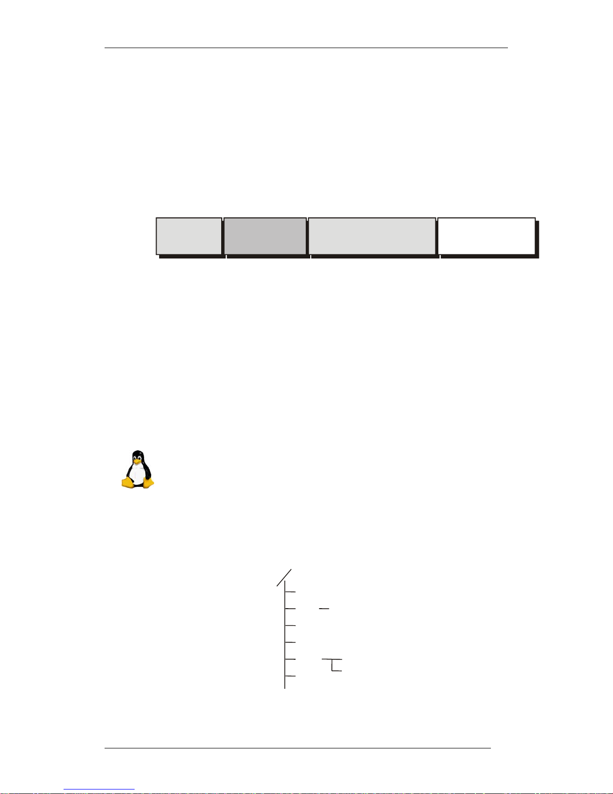
owa23X Platform Integrator’s Manual
BOK-100 1065-C-owa23X Platform Integrator's Manual
35
4.5 Firmware Specifications
4.5.1 General Description of Firmware
In order to manage the platform resources, a complete library of APIs, for GPS
management, Internet connection, management of the interfaces, GSM/GPRS
functions and other services is made available. Thus, the developer does not
need to consider about low level hardware drivers and protocols, and can focus
on the application by means of user-friendly APIs.
The main structure of the owa23X software system is the following:
Figure 4.5.1.1 owa23X Software structure
4.5.1.1 Boot Loader
The boot loader is the booting system that manages the kernel and file system
flashing.
It waits for 2 seconds before starting up Linux. During this time, if the boot
loader receives a character different than ENTER through serial port, it starts
up Linux immediately. If it receives ENTER, it enters in command mode;
therefore the received characters are interpreted as commands. Once finished
in command mode, send
boot
command for Linux start up. See 3.5.1
4.5.1.2 Linux Kernel
This is a Linux standard kernel, version 2.4.18 with MMU option. As this is a
standard kernel, PC developed applications are easily made compatible with
owa23X platform. Also this kernel can be updated to follow standard kernel
revisions.
4.5.1.3 owasys File System
This file system follows the conventional structure of a Linux system and is
shown as follows:
Figure 4.5.1.3.1 File system structure
bin
etc
lib
initd
dev
usr
bin
sbin
tmp
Linux Kernel
owasys File System
User Hard Disk
Boot
Loader
Page 42

owa23X Platform Integrator’s Manual
BOK-100 1065-C-owa23X Platform Integrator's Manual
36
bin and sbin: these directories include Linux basic commands for operating
system utilities and embedded system shell.
etc: in this directory all configuration files and booting parameters are
recorded.
dev: a directory with all peripherals specifications.
tmp: in this directory, the user can store files during owa22X operation. This
information will be lost each time the system boots.
lib: with all Linux standard libraries and APIs libraries.
usr: contains commands, libraries, documentation and other files that do not
change during normal operation.
4.5.2 User ‘Hard Disk’
The user hard disk is mounted in /
hom
e directory:
Figure 4.5.2.1 User hard disk structure
This directory can be used as a 5Mbyte hard disk, so all the stored information
in this directory is recoverable when rebooting the unit. In this directory, user
can create the desired directory structure and store all kind of files in it.
The information stored in
/home
directory is written in non-volatile Flash
memory. Everything stored outside
/home
is written in volatile RAM memory.
Flash memory behaves like a computer hard disk, but it guarantees only a
limited number of write cycles per sector and unlimited number of readings.
Thus, it is important that user does not write every second in Flash memory, it
is better if he writes first into RAM memory all the information (not in
/home
directory) and then copies the file into Flash memory. The user can compress
the file with gzip utility, before copying the file to
/home
memory so that he has
more free memory available.
gzip
and
gunzip
utilities are included in the
owa2X file system. See Programming Guide for a better understanding in the
use of Flash memory
4.5.3 Starting to Develop the Customer Application
Once the cross compiler is installed (See section 3.4.1), the user can use this
compiler in the desired development environment, for example,
KDeveloper
.
To use the available APIs library functions, add the includes to owa22X files in
application header files and compile the application using the provided cross
compiler.
owa23X files to be included in customer header files are:
<owa2x/RTUControlDefs.h>
bin
etc
lib
initd
dev
usr
bin
sbi
n
tmp
home
Page 43

owa23X Platform Integrator’s Manual
BOK-100 1065-C-owa23X Platform Integrator's Manual
37
<owa2x/IOs_ModuleDefs.h>
<owa2x/ GSM_ModuleDefs.h>
<owa2x/ GPS_ModuleDefs.h>
<owa2x/ INET_ModuleDefs.h>
<owa2x/ can.h>
<owa2x/ SerialDefs.h>
<owa2x/ owa2x_pm.h>
All
API module libraries
have been written in C++ Language using the
KDeveloper
environment with
gcc compiler
tool, under
LINUX Red Hat 7.3
Operating system
. It is recommended, to avoid problems from the development
environment, to use the same language, compiler, and environment when
possible.
Usually, a Client application is comprised of a main executable program, and a
set of libraries. This set of libraries can be of two types: system libraries, both
static and dynamically loaded; and
owa23X API module libraries
, always used in
a dynamic way.
Once an application is defined, what the user has to do is select which libraries
will be used and get pointers to the needed functions, using them as C
language normal functions. For a better use of system resources, it is
recommended to unload all functions of a library, as well as the library itself,
when it is known that it will not be used anymore in the program’s scope. Also,
it is not necessary to get all functions’ pointers in a library, if some of them will
not be used in the program: it is a waste of memory, and system resources
which can be useful for other tasks, and will improve the system behaviour in
general.
In the example of chapter 4.5.3.1, a simple application is explained. Thus the
mechanism of loading and unloading libraries and how to access libraries
functions can be understood.
Page 44

owa23X Platform Integrator’s Manual
BOK-100 1065-C-owa23X Platform Integrator's Manual
38
4.5.3.1 Example of a Simple Application
This is the source code of a simple application. In its main block, it loads an
external library (in this case,
RTUControl
module library), gets some pointers to
its functions, and unloads the library. Really, this program doesn’t do anything
very useful, but shows the working mechanism that will be the same for all the
API module libraries and applications.
#include <dlfnc.h> // For use dynamical loading/unloading libraries.
#include <stdlib.h> // For printf() function.
int main( void)
{
// Variable definitions: [1]
void *LibHandle = NULL; // Pointer to
store the library handle.
INT ( *FncGetFirstFreeSignal)( INT *);// Pointer to get
//GetFirstFreeSignal() function.
INT signal;
// Here loads the library: [2]
LibHandle = dlopen( "/libs/libRTUControl.so.0.0.0", RTLD_LAZY);
if( ! LibHandle) {
printf( "No shared library \"/libs/libRTUControl.so.0.0.0\”
found...");
return;
}
// How to get a function pointer: [3]
FncGetFirstFreeSignal = ( INT ( *) ( INT *)) dlsym( LibHandle,
"GetFirstFreeSignal");
if( dlerror() != NULL) {
printf( "No GetFirstFreeSignal () found...\n");
}
// How to call the function: [4]
( *FncGetFirstFreeSignal)(&signal);
// How to unload the library [5]
dlclose( wLibHandle);
}
There are five different sections in the program (identified by a
[x]
mark):
[1] Variable definition section:
In this section the Client application must define mainly two sets of variables:
Handlers for every API module library to load, each of them with different
name.
Pointers, of the same type as API module library’s function, for all the functions
to be used in the program scope. It is important to indicate that this pointer can
NEVER have the same name as the function to be linked to (that is because the
compiler can misinterpret internal name tables). In this example, the function’s
name is GetFirstFreeSignal, and the pointer’s name is FncGetFirstFreeSignal.
Page 45

owa23X Platform Integrator’s Manual
BOK-100 1065-C-owa23X Platform Integrator's Manual
39
[2]: Loading the library:
At this point, the required library is loaded. Its full path and name must be
passed to
dlopen()
function, and it is recommended to do a load control test
before proceeding to get functions pointers.
[3]: Getting pointers to functions:
Now it is the moment to get a pointer for each library’s function which will be
used in the program. As it can be seen in the code, it is necessary to do a
casting for the type of the pointer filled, and it is necessary to call later to
dlerror()
function for checking if the pointer is valid or not (checking pointer
against value NULL is not valid, because function number 0 can be got with this
function…)
[4]: Calling function’s pointer:
This is the way of calling a function’s pointer, with the name of the function
enclosed in a “( * …)” sequence. Although in this case no return error is
checked, it is recommended to check if return code of the function is equal to
NO_ERROR code, indicating a correct execution of the function.
[5]: Unloading the module library:
To save system resources as handler, memory, etc., once a dynamical library is
not going to be used again, it must be unloaded. If system resources are not a
problem, simply wait to the end of the program for unloading all libraries.
This is the simplest example of client application. More cases of applications
will implicate loading and unloading more than only one library, different sets
of functions’ pointers, multithread, etc. Practice and developments will indicate
which method to follow in each case.
4.5.4 Loading the Customer Application
Once the system has booted, the customer application can be copied to
/home
directory (See section 3.5.2 and 3.5.3).
Also, the user can configure the unit to run the application automatically during
start-up, by including a command in a configuration script located in
/home
.
The name of this script is:
userinit.sh
.
For example, if the name of the application program is
application_name
, this
must be included in the configuration script:
/home/ application_name
You can also insert in userinit.sh file the following instructions or
/home/ application_name &
4.5.5 Available APIs
In this section there is an overview of the available APIs and an explanation of
their functionality. For further information about the APIs and their functions, it
is recommended to read through references [1] and [2]
4.5.5.1 API for owa23X Control
This API provides a Select Control function to manage synchronous and
asynchronous ports and a centralized system time.
Page 46

owa23X Platform Integrator’s Manual
BOK-100 1065-C-owa23X Platform Integrator's Manual
40
4.5.5.2 API for GSM/GPRS
The communication with the GSM module is done with the GSM and GPRS APIs.
Sending and receiving SMSs and making dial calls are some of the functions
provided.
4.5.5.3 API for GPS
Getting the positioning info and sending NMEA commands through the UART,
are some developed functions included in this API (only for owa23A units).
4.5.5.4 API for Interfaces
The functions of this API facilitate the management of owa23X I/Os, UARTs and
audio signals.
4.5.6 Power Management
The Power Management functions which control the operating modes of
owa23X (See section 4.4) are in the libRTUControl library. For more information
about this driver see ref. [1] and [2].
4.5.7 RS232 Driver
RS232 driver is used to control the RS232 interface of the multipurpose
connector. For more information about this driver see ref [1] and [2].
4.5.8 Software Application Notes
In the development kit CD the source files (.cpp and .h) of some example
applications are available.
Page 47
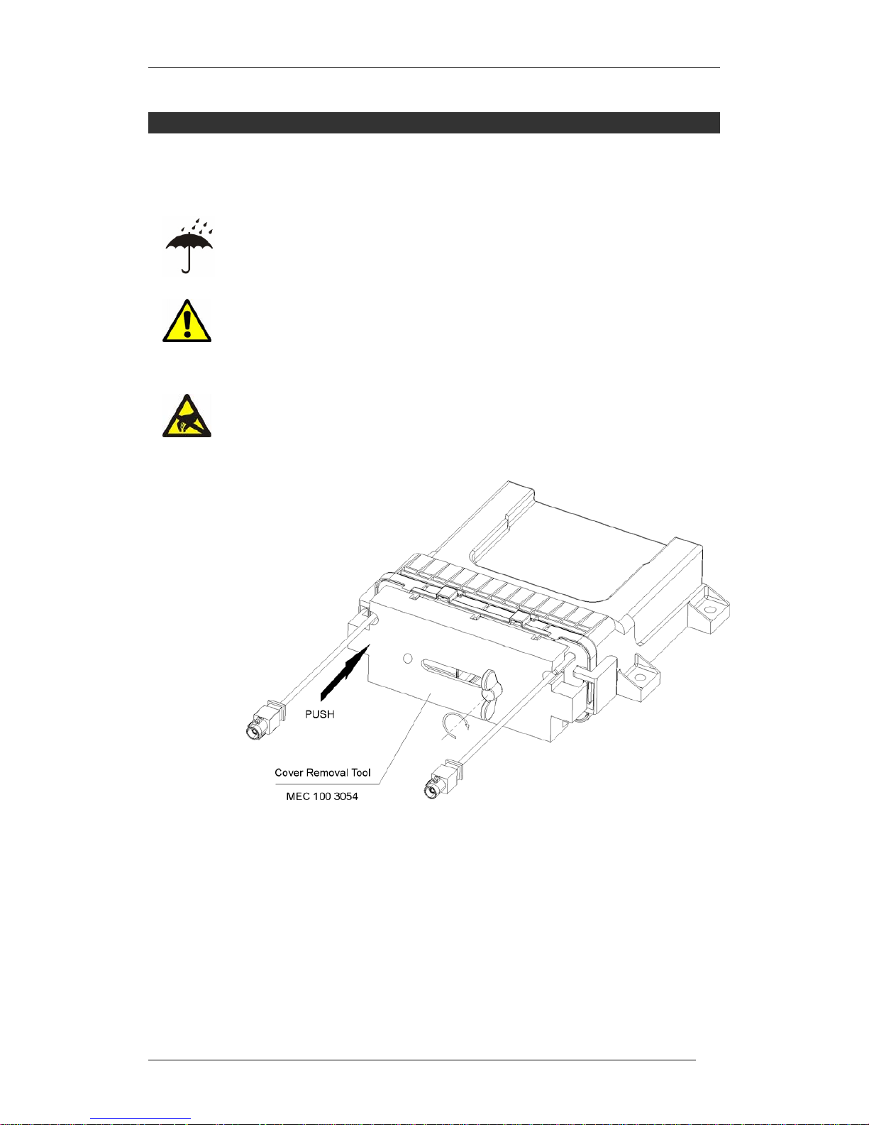
owa23X Platform Integrator’s Manual
BOK-100 1065-C-owa23X Platform Integrator's Manual
41
5 Installation
This section describes mounting and connection of the owa23X.
5.1 SIM Card Installation
Before opening the owa23X to install the SIM card, ensure that the unit is dry. If
the unit has previously been exposed to water, place the unit in a warm dry
location for a few hours to ensure that all water has evaporated from the seals.
This is to ensure that no water droplets enter the unit when it is opened.
If water is allowed to enter the unit then it could be damaged.
5.1.1 Open Cover
The main board in the unit is sensitive to electrostatic discharge, so before
opening the owa23X ensure that you are wearing the ESD wrist strap provided
in the Development Kit and that it is connected to a good ground point. A
suitable ground can usually be found on the front of an oscilloscope or
laboratory power supply, or an ESD grounding mains plug. The owa23X should
ideally be opened on an ESD safe work bench.
Figure 5.1.1.1 Opening front cover
Open the front cover with the removal tool (MEC 100 3054), supplied in the
Development Kit. Gently tighten clockwise the screw, while pushing with one
finger the left side (see figure), until the cover latches release.
Once the cover is opened remove the release tool, and then slide the main
board out of the unit taking care not to touch or damage any of the components
on the board.
Page 48
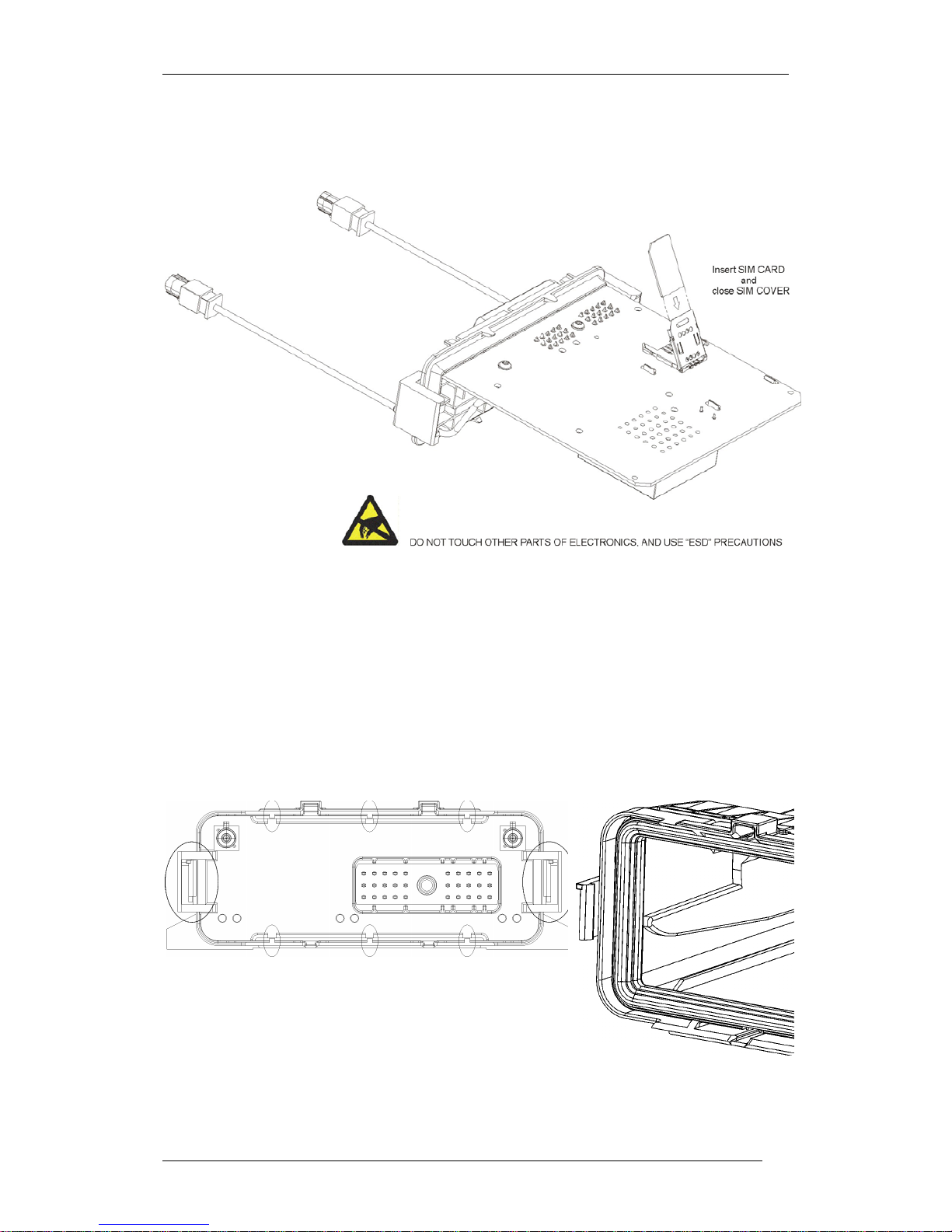
owa23X Platform Integrator’s Manual
BOK-100 1065-C-owa23X Platform Integrator's Manual
42
5.1.2 Insert SIM
The SIM holder is located on the bottom of the main board. Open the SIM door
by sliding it back and up. Insert the SIM with the contacts face down and the
corner as indicated on then holder.
Figure 5.1.2.1 Inserting SIM
After placing the SIM inside, close the SIM door and click it into place.
5.1.3 Close Cover
Slide the main board back into the housing ensuring that the connector pins do
not damage the blue seal, and press until all seal latches have clicked closed.
There are 8 latches which should be checked to ensure that they have closed
correctly.
LATCHES
DETAIL
Figure 5.1.3.1 Latches
Page 49

owa23X Platform Integrator’s Manual
BOK-100 1065-C-owa23X Platform Integrator's Manual
43
5.2 Antenna Installation
5.2.1 Location
Permanently installed antennas are preferred over magnetic, glass or body lip
mounts for anything other than for low power or temporary installations.
However, a magnetic mount antenna is a good tool for checking the proposed
fixed antenna location for unwanted effects.
Glass mounted antennas are suitable for mounting on vehicles. In this case
they should be kept as high as possible in the centre of the rear window or
windshield. Some vehicles use glass that contains a thin metallic coating for
defrosting or to control solar gain; glass mount antennas may NOT function
properly when mounted on this type of glass.
If a magnetic mounted antenna is used, take care to locate the magnetic base in
a location which avoids interference to the compass mechanism, since magnets
may affect the accuracy or operation of the compass. If metallic panels are
used, do not block the reception paths for installed antennas such as Global
Position Satellite Receivers, if so equipped.
For an optimum performance of antennas, consider these aspects:
The antennas should not be shielded by any metal object or other
impenetrable material.
The antennas have to be safe from damage during normal vehicle
operation and maintenance.
GPS antenna should not be shielded from satellite signals by metal
objects or other impenetrable materials. GPS antennas should have
an unobstructed view of the sky.
Separate GSM and GPS antenna at least 50 cm where possible.
Choose a location with access both above and below the antenna-
mounting surface. This access is required for installing fasteners
and for routing the antenna cable.
Keep the GSM antenna as separate as possible from the
microphone and loudspeaker when hands-free option is used.
5.2.2 Antenna Tuning
It is important that the antenna is properly tuned and return loss is kept better
than 10dB to achieve a low Voltage Standing Wave Ratio (VSWR) less than 2.0:1,
and to avoid RF current on the antenna cable shield.
5.2.3 Antenna Cable Routing
Always use a high quality, one-piece coaxial cable. Connector quality and
termination techniques are quite important.
The antenna cables should be treated in the same way as the control and power
cables. Avoid sharp edges and pinches and keep the cable as short as possible.
Also avoid routing the antenna cable in parallel with other control or power
wiring over long distances. If it is necessary to cross over wiring, cross at right
angles.
5.3 Power and Signal Connection
To connect owa23X cables follow the following instructions:
Page 50

owa23X Platform Integrator’s Manual
BOK-100 1065-C-owa23X Platform Integrator's Manual
44
Switch off owa23X power.
Allow sufficient cabling to enable the removal of the equipment.
Ensure cables are not corrupted or rubbing against sharp objects.
The owa23X does not include internal fusing. An external fuse should be
included in the positive Vin supply with a rating of 5A to protect the cables and
input circuitry in case of a fault condition.
See section 4.2.4 for connector pin out and cable colour information.
The cable assembly can be screwed into place using the 1/4” AF nut driver
(supplied in the Development Kit).
5.4 Choosing a Location
Choose a location for owa23X which allows for convenient routing and
connection of the antenna and interface cables, and which has access to power
source, on-off button, and status LEDs. When selecting a mounting location,
avoid the following hazards:
Direct exposure to weather.
Excessive heat or cold.
High vibration areas.
Corrosive fluids and gases.
Direct exposure to solar radiation.
Do not obstruct drivers view or impede operation.
5.5 Mounting the Unit
Always keep cabling as short as possible.
The owa23X can be mounted horizontally, vertically, or in any convenient
orientation, but we recommend maintaining the indicator lights visible since it
is an advantage when troubleshooting the unit.
The hole locations are shown in section 4.1. Self tapping or M5 screws can be
used for mounting (not supplied).
5.6 Antenna Connector Protection
The in-line antenna connectors can be protected from dust and water with the
special enclosures (MEC 100 3009) available from
owasys.
Use external antennas with RG174/U coaxial cable. External diameter for the
cable 2.8mm
+0.2/-0.0
Connect first your antennas, and then assemble the connector latches as in the
figure below.
Use the ties to assure the sealing of the protector. Place them at the flanges as
in the figure below
Page 51
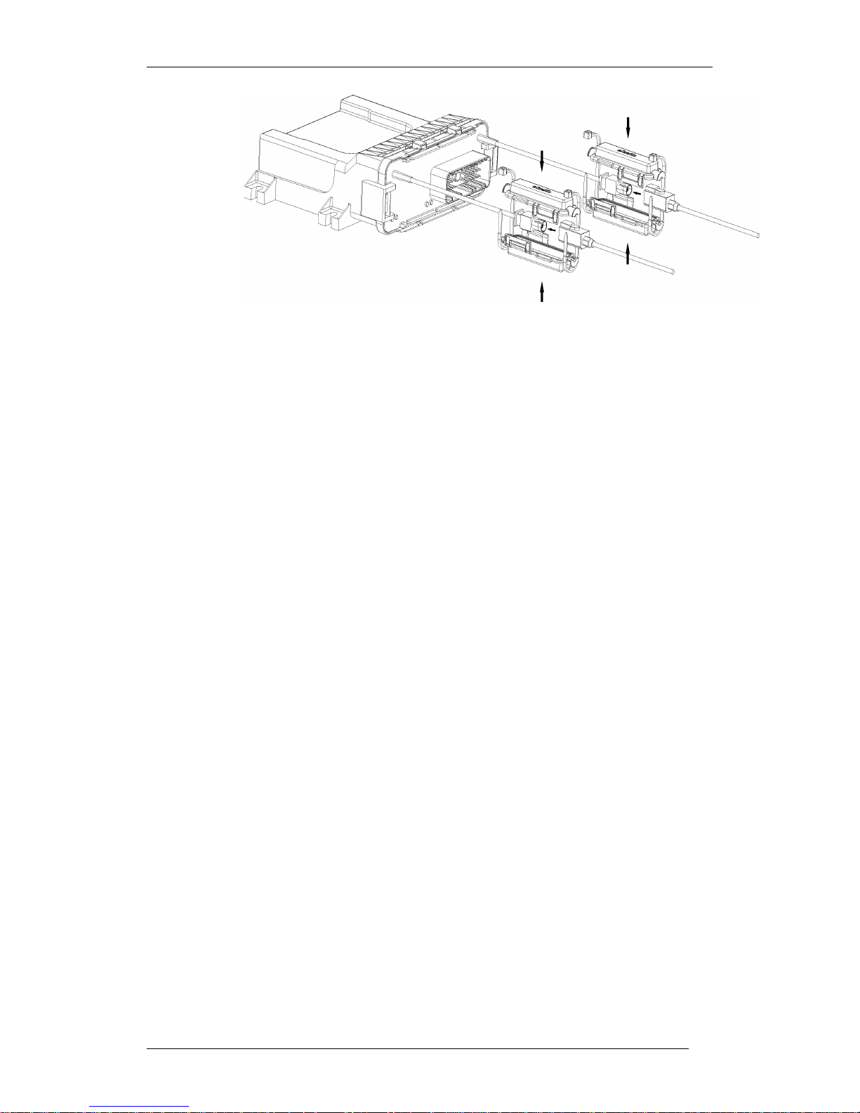
owa23X Platform Integrator’s Manual
BOK-100 1065-C-owa23X Platform Integrator's Manual
45
Figure 5.6.1 Protecting antenna connectors
The antenna sealing enclosures are only waterproof it the cable ties are
installed with the appropriate tool. The one recommended by Owasys is the
Farnell Cable Tie Installation Tool 1015659.
Page 52
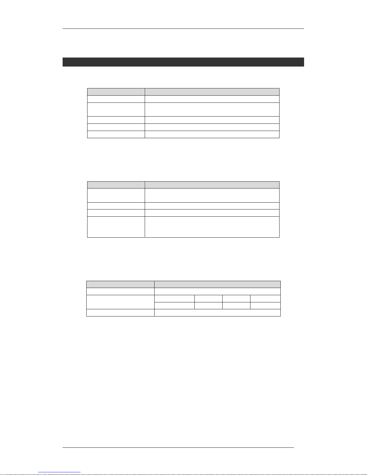
owa23X Platform Integrator’s Manual
BOK-100 1065-C-owa23X Platform Integrator's Manual
46
6 Te chnical Data Summary
General Specification
Item Specification
Processing Capacity 32 bits RISC ARM7 core up to 60 MIPS at 70MHz
Available Memory for
user
4 Mbyte Flash with 100K rewrite cycles.
8,5 Mbyte RAM (2Mb RAM disk + 6,5Mb RAM)
Status Lights Green, Orange, Yellow and Red
CE Mark According to R&TTE Directive1999/5/EC
e Mark According to 2006/28/EC Directive
Table 6.1 General specification
Mechanical Description
Item Specification
Max Dimensions
(mm.)
146 x 153 x 56 mm (excluding connectors)
Weight 400 grams
Material Glass reinforced plastic
Connectors 2 FAKRA plugs (GSM & GPS)
30 way Multipurpose Connector
SIM Card Holder
Table 6.2 Mechanical description
Power Interface
Item Specification
Power Supply 6 to 40 Vdc
VIN 6V 12V 24V Power Consumption
(maximum)
I
IN
1.5 A 0.8 A 0.4 A
Connector 30 way incorporated in enclosure
Table 6.3 Power interface
Page 53
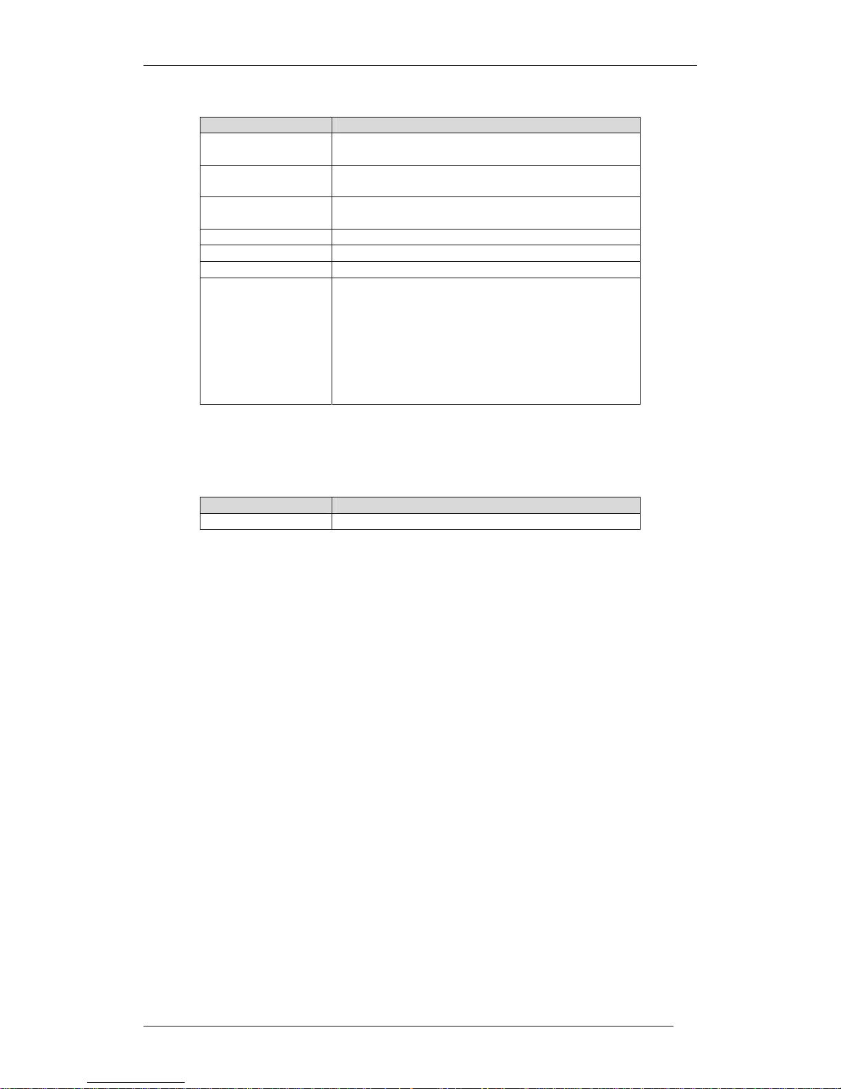
owa23X Platform Integrator’s Manual
BOK-100 1065-C-owa23X Platform Integrator's Manual
47
GSM/GPRS Specifications
Item Specification
Frequency bands Quad Band GSM 850/ EGSM900 / GSM1800/
GSM1900
Power 2 Watt at GSM850/EGSM900 and 1 Watt at
GSM1800/GSM 1900
GPRS Class B
Class 10 (4+2)
Operations Audio calls, Data calls, Short Message Service.
SIM Integrated holder, 3 Volt
Antenna Connector FAKRA Plug (bordeaux)
Antenna
Requirements
Impedance: 50Ω
Typical Gain: 0dBi +/- 1dB
Frequency bands:
GSM850: 824 - 894 MHz
EGSM900: 880 –960 MHz
GSM 1800: 1710 –1880 MHz
GSM 1900: 1850 - 1990
VSWR: Better than 2.0:1
Table 6.4 GSM/GPRS specifications
Ethernet Specifications
Item Specification
Ethernet 10Base-T
Table 6.5 Ethernet specifications
Page 54
owa23X Platform Integrator’s Manual
BOK-100 1065-C-owa23X Platform Integrator's Manual
48
GPS Specifications
Only for the owa23A range of products
Item Specification
Receiver L1 frequency, C/A code, 16-channel continuous
tracking receiver
Update Rate
≤ 4Hz
Accuracy 2.4 meters CEP
Signal Acquisition Cold Start: 34 sec
Warm Start: 33 sec
Hot Start: < 3.5 sec
Signal Reacquisition: < 1 sec
Datum WGS-84
Antenna Connector Fakra Plug (blue)
Antenna
Requirements
Active antenna 1.
Impedance: 50Ω
Antenna typical gain: 4.0 dBic
Active Antenna recommended gain:
min= 15 dB, max= 45 dB. (max noise figure = 1.5 dB)
Frequency: 1575.42MHz
VSWR: Max 2.0:1
Active antenna
detection circuitry
Active Antenna Power Supply: +3.0V @ 30mA current
• open circuit detection: 5 mA
• short circuit detection: 50 mA.
Table 6.6 GPS specifications
L1 Frequency is one of the two radio frequencies transmitted by the NAVSTAR
satellites (GPS constellation). L1 frequency is 1575.42 Mhz.
C/A code (Coarse Acquisition Code) contains the information to fix position and
time. This code (also known as “civilian code”) is a sequence of 1023
pseudorandom binary biphase modulations on the GPS carrier (L1 frequency).
CEP (Circular Error Probability) means the radius of an horizontal circle,
centred at the antenna’s position, containing 50% of the fixes.
Cold Start: in this scenario, the GPS receiver does not know the last position,
approximate time and satellite constellation.
Warm Start: in this scenario, last position, approximate time and almanac are
known. As a result, fix acquisition is faster.
Hot Start: the Ephemeris data not older than 2 hours are available. This data
allows a faster acquisition.
Reacquisition: this figure gives the time required to get lock on a satellite, in
case that the signal has been blocked for a short time (as it usually happens in
urban areas, due to buildings and other obstacles).
1
The use of a pasive antenna requires a DC-Block between the GPS antenna connector and the GPS passive antenna. In
this case the open/short detection will not function.
Page 55
owa23X Platform Integrator’s Manual
BOK-100 1065-C-owa23X Platform Integrator's Manual
49
Environmental Specifications
Item Specification
Complete operation -30 ºC to +75 ºC Operating Temperature
GSM off -40 ºC to +85 ºC
Storage Temperature -40ºC to +85 ºC
Sinusoidal Vibration IEC 60068-2-6 test Fc
Random Vibration IEC 60068-2-64, test Fh
Mechanical shock IEC 60068-2-27, test Ea
Bumps IEC 60068-2-29, test Eb
IP Protection IP67
DustProof. Protection against penetration with wire.
Protected against temporary inmersion (1m for 30 mins).
Table 6.7 Environmental specifications
Battery Backup
Only for the owa23X/ units fitted with the optional battery (POP 100 2100).
Item Specification
Time to recharge 12 hours when owa23X is powered
Charging temperature range1 0 ºC to 45 ºC
Cell type Li-Ion 3.7V 1000mAh
Discharging temperature range -20 ºC to + 60 ºC
Table 6.8 Battery backup
1
Battery Charging is automatically disabled outside this range.
Page 56

owa23X Platform Integrator’s Manual
BOK-100 1065-C-owa23X Platform Integrator's Manual
50
7 owa23X Firmware Advanced Configuration
These instructions are only for Linux advanced users. If the configuration of
owa23X firmware is changed, the user is responsible of all these changes. In
case the device was not able to accurately operate, it is not the responsibility of
OWASYS
As is explained in section 4.5.1.3, owa23X file system has fixed features and
structure. Every time the device is powered on, the file system is decompressed
and copied from Flash memory to RAM memory. If customer changes the
content of
/etc, /bin, /sbin, /lib, /usr, /sbin, /proc, /tmp
… directories, these
information is lost every time the device is powered off and on.
Owasys realizes that some advanced users may be interested in changing some
configuration files or including any files in these directories. For doing this,
follow these instructions:
Create a directory named
@sysinit
under /
home
directory.
(
/home/@sysinit
).
Under this directory, the customer can create a structure of
directories similar to the file system structure in Fig. 4.5.1.3.1. All
files stored by the user in these directories will replace the original
ones into the Owasys file system after system boots.
For example, if customer creates a file
/home/@sysinit/etc/ initab
This file will replace, when system boots, the original
/etc/initab
file
Moreover, as the information stored under
/home
directory is not erased when
switching off the device, user can customize owa23X firmware configuration.
If user realizes that customized firmware does not work properly, Owasys
factory configuration can be reloaded. For recovering the initial configuration,
in boot loader command mode you can use either:
bootl2
command to skip
/home/@sysinit
directory content copy
erasejffs
command to format Flash memory and erase everything under /home
directory
See 3.5.1 for a description of available booting commands
7.1 Ethernet
Ethernet is the most widely used standard for wired networking between
computers. It is based on the IEEE 802.x family of standards.
The Ethernet interface provided within the owa2x family is type 10BaseT, this
interface is capable of handling 10 Mbps via a RJ45 connector.
Owa23x devices with Ethernet include a kernel with IP routing and firewall
capabilities.
7.1.1 Ethernet interface activation
The initeth script performs all the tasks needed to start using the Ethernet
interface from the application, i.e. loads the firmware modules, power on the
hardware means, etc.
Page 57

owa23X Platform Integrator’s Manual
BOK-100 1065-C-owa23X Platform Integrator's Manual
51
# initeth
Once we have executed it, we can start using the device just by configuring it
with the right system commands.
As a learning example we can see how an owa23x-ETH device might be
configured within a LAN.
First, an IP address must be assigned to the owa23x Ethernet device, ifconfig
command is used for that purpose. The identifier of the device will always be
eth0, the IP address in the example will be 192.168.2.100 and the net mask
used 255.255.255.0
# ifconfig eth0 192.168.2.100 netmask 255.255.255.0
By executing the ifconfig command with no arguments we can see that the
device has been successfully activated.
# ifconfig
eth0 Link encap:Ethernet HWaddr 00:50:02:37:40:02
inet addr:192.168.2.100 Bcast:192.168.2.255 Mask:255.255.255.0
UP BROADCAST RUNNING MULTICAST MTU:1500 Metric:1
RX packets:180 errors:0 dropped:0 overruns:0 frame:0
TX packets:0 errors:0 dropped:0 overruns:0 carrier:0
collisions:0 txqueuelen:100
RX bytes:23289 (22.7 kiB) TX bytes:0 (0.0 iB)
Interrupt:32
We can also test that the owa2x has become part of the LAN by accessing a
valid IP address within it. The ping command allows us to test if another IP
address is reachable.
# ping 192.168.2.1
PING 192.168.2.1 (192.168.2.1): 56 data bytes
64 bytes from 192.168.2.1: icmp_seq=0 ttl=255 time=10.0 ms
64 bytes from 192.168.2.1: icmp_seq=1 ttl=255 time=0.0 ms
64 bytes from 192.168.2.1: icmp_seq=2 ttl=255 time=0.0 ms
--- 192.168.2.1 ping statistics ---
3 packets transmitted, 3 packets received, 0% packet loss
round-trip min/avg/max = 0.0/3.3/10.0 ms
In case that we are interested in having access to other networks, as internet,
we can set the default gateway for the owa2x, by using the route command, as
done below.
Page 58

owa23X Platform Integrator’s Manual
BOK-100 1065-C-owa23X Platform Integrator's Manual
52
# route add default gw 192.168.2.254
Once that the gateway for accessing internet has been defined, it might be also
interesting to define the DNS servers for resolving domain names. For setting
the primary and secondary DNS IP addresses the /etc/resolv.conf must be
modified. Keep in mind that this file is stored in RAM, so if we want that our
changes remain it should be created in the folder /home/@sysinit/etc/.
nameserver 212.55.8.132
nameserver 212.55.8.133
Finally, to test that the network configuration has been successfully set we can
ping google.
# ping www.google.com
PING www.google.akadns.net (216.239.59.104): 56 data bytes
64 bytes from 216.239.59.104: icmp_seq=0 ttl=240 time=140.0 ms
64 bytes from 216.239.59.104: icmp_seq=1 ttl=240 time=80.0 ms
64 bytes from 216.239.59.104: icmp_seq=2 ttl=240 time=80.0 ms
64 bytes from 216.239.59.104: icmp_seq=3 ttl=240 time=130.0 ms
64 bytes from 216.239.59.104: icmp_seq=4 ttl=240 time=90.0 ms
7.1.2 Ethernet interface deactivation
The first step that must be carried out to deactivate the Ethernet interface is to
put the device in down state, ifconfig shell command is used as shown below.
# ifconfig eth0 down
Finally, driver module must be unloaded by executing the rmeth script provided
within the file system.
# rmeth
7.2 Routing and Firewall tools
owa21-ETH provides embedded Routing capabilities.
Routing means come integrated in the kernel and can be handled by using the
“route” command. For example, to get the current routing table, enter:
# route
For more information about “route” command, please refer to the manual
pages in your Linux distribution.
Page 59

owa23X Platform Integrator’s Manual
BOK-100 1065-C-owa23X Platform Integrator's Manual
53
Firewall capabilities are handled by using the “iptables” command. This
command also provides means to, for example, perform Network Address
Translation (NAT). This command, however, is not natively integrated and must
be installed before using it.
For more information about “iptables” command, please refer to the manual
pages in your Linux distribution.
There are a couple of sample scripts called “owaRouting” and “owaNAPT,
available in the Development Kit, under “/Tools/Router&Firewall”, that
illustrate how “iptables” is used for both, adding some basic firewall rules, and
for activating NAT and NAPT over an interface.
7.3 Remote Firmware Upgrade
If you plan to remotely upgrade the firmware, please refer to Programming
Reference to learn how to use the function “WriteFile”.
When doing this process please observe following notes:
Stop all other applications before starting to upgrade the firmware
After upgrade file/s has been transferred, reboot the system to load the new
firmware
The WriteFile() function unmounts the /home directory before starting to
download the file and mounts it after finishing. This is to avoid multiple access
to the Flash at the same time. So, applications calling this function must be run
OUTSIDE directory /home
Page 60

owa23X Platform Integrator’s Manual
BOK-100 1065-C-owa23X Platform Integrator's Manual
54
8 References
Ref. Doc. Number Description
[1] DESI-BOK-100-1068 Programming Guide
[2] DESI-BOK-100-1069 Programming Reference Manual
 Loading...