

Page 1
Version 25 September 2009 (Rev. 0)
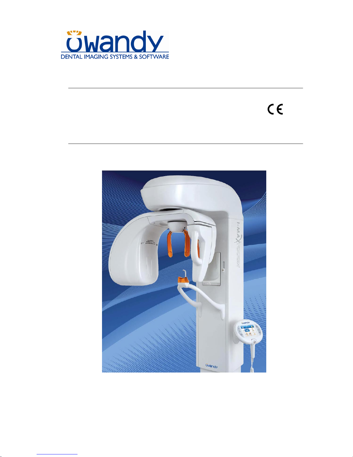
I-Max Touch 0459
(110-120V version)
User's Manual
Page 2

USER'S MANUAL
Contents
(Rev. 0) I-Max Touch (110-120V)
i
Contents
1. INTRODUCTION 1
1.1 Icons appearing in the manual ............................................................... 2
2. SAFETY INFORMATION 3
2.1 Warnings ................................................................................................ 4
2.2 Environmental risks and displacement ................................................... 7
2.3 Symbols used ......................................................................................... 8
3. CLEANING AND DISINFECTION 9
4. DESCRIPTION 10
4.1 Identification labels and laser labels ..................................................... 10
4.2 Functions, models and versions............................................................ 12
4.2.1 Basic version ............................................................................ 12
4.2.2 Version with cephalometric device ............................................ 13
5. TECHNICAL CHARACTERISTICS 14
5.1 Dimensions........................................................................................... 19
5.2 Loading curve of the tube and cooling curve of the anode ..................... 21
5.3 Applied safety regulations..................................................................... 23
5.4 Note on constant magnification for Panoramic and TMJ (mouth
open/closed) examinations ................................................................... 24
5.5 Measurement method of technical factors (paragraph for
authorised personnel) ........................................................................... 25
5.6 Verification method of technical factors (paragraph for
authorised personnel) ........................................................................... 26
6. GENERAL INSTRUCTIONS FOR USE 28
6.1 Control panel - description and functions ............................................. 28
6.1.1 Key function description........................................................... 33
6.1.2 Acquired image display description .......................................... 35
6.1.3 Pen Drive function description.................................................. 36
6.2 Digital Sensor ....................................................................................... 37
6.2.1 Inserting the sensor in the sensor holder.................................. 38
6.2.2 Release of the sensor from the sensor holder ............................ 39
6.3 Switching on the device ........................................................................ 40
6.4 Positioning of chin support ................................................................... 42
Page 3

USER'S MANUAL
Contents
I-Max Touch (110-120V) (Rev. 0)
ii
6.5
Panoramic examination ........................................................................ 43
6.5.1 Preparation of the device .......................................................... 44
6.5.2 Anatomic / manual exposure ................................................... 47
6.5.2.1 Anatomic exposure .............................................................. 48
6.5.2.2 Manual exposure ................................................................. 49
6.5.3 Preparation of the patient ......................................................... 51
6.5.4 Making an exposure ................................................................. 53
6.6 TMJ examination .................................................................................. 57
6.6.1 Preparation of the device .......................................................... 58
6.6.2 Anatomic / Manual Exposure................................................... 59
6.6.2.1 Anatomic exposure .............................................................. 60
6.6.2.2 Manual exposure ................................................................. 61
6.6.3 TMJ closed mouth .................................................................... 62
6.6.3.1 Preparation of the patient..................................................... 62
6.6.3.2 Carrying out the first exposure (mouth closed)...................... 64
6.6.4 TMJ open mouth ...................................................................... 66
6.6.4.1 Preparation of the patient..................................................... 66
6.6.4.2 Carrying out the second exposure (mouth open) ................... 68
6.7 SINUS examination ............................................................................... 71
6.7.1 Anatomic / Manual Exposure................................................... 72
6.7.1.1 Anatomic exposure .............................................................. 73
6.7.1.2 Manual exposure ................................................................. 74
6.7.2 Preparation of the patient ......................................................... 75
6.7.3 Making an exposure ................................................................. 77
6.8 Cephalometric examination .................................................................. 80
6.8.1 Preparation of the device .......................................................... 81
6.8.2 Anatomic / Manual Exposure................................................... 84
6.8.2.1 Anatomic exposure .............................................................. 85
6.8.2.2 Manual exposure ................................................................. 86
6.8.3 Preparation of the patient ......................................................... 87
6.8.4 Making an exposure ................................................................. 88
6.9 Examination to assess bone growth (Carpus)........................................ 91
6.9.1 Preparation of the device .......................................................... 92
6.9.2 Preparation of the patient ......................................................... 95
6.9.3 Making an exposure ................................................................. 96
6.10 Messages on display ............................................................................. 98
6.10.1 Error message with error code E000 ÷ E199 ............................. 99
6.10.2 Error message with error code E200 ÷ E299 ............................. 99
Page 4

USER'S MANUAL
Contents
(Rev. 0) I-Max Touch (110-120V)
iii
6.10.3
Error message with error code E300 ÷ E399 ........................... 100
6.10.3.1 Error message with code error E300 ÷ E303 ....................... 100
6.10.3.2 Error message with code error E320 ÷ E323 ....................... 100
6.10.3.3 E340 - Sensor holder not in PAN position ........................... 100
6.10.3.4 E360 / E361 - X-ray button pressed during start up or axis
movement 100
6.10.3.5 E362 - X-ray button released during examination............... 101
6.10.4 Error message with error code E400 ÷ E402 ........................... 102
6.10.5 Error message with error code E700 ÷ E799 ........................... 102
6.10.5.1 E755 – Safety Buckup Timer intervention........................... 102
6.10.5.2 E774 - X-rays button not pressed....................................... 102
6.10.5.3 E775 - X-rays button released prematurely......................... 102
6.10.6 Error message with error code E850 ÷ E852 ........................... 103
6.10.6.1 E850 - One or more keys appear to be pressed on start-up . 103
6.10.6.2 E851 - Column key pressed................................................ 103
6.10.6.3 E852 - Key "Patient Entrance" pressed during the movement103
6.11 Research and correction of possible defects in dental X-rays .............. 104
6.11.1 Faults due to the wrong positioning of the patient .................. 104
6.11.2 Defects due to wrong data setting........................................... 105
6.11.3 Defects due to the device ........................................................ 106
6.12 Analysis of the problems on the panoramic examinations ................... 107
6.12.1 Proper positioning of the patient............................................. 108
6.12.1.1 Errors due to poor positioning of patient............................. 110
6.12.1.2 Images with artefacts ......................................................... 117
6.13 Storing of automatical exposure parameters ....................................... 120
6.13.1 Table of pre-set anatomic parameters..................................... 121
7. MAINTENANCE 122
No part of this publication can be reproduced, transmitted, transcribed or
translated without the approval of Owandy.
This manual in English is the original version.
Page 5

USER'S MANUAL
Contents
I-Max Touch (110-120V) (Rev. 0)
iv
THIS PAGE IS INTENTIONALLY LEFT BLANK
Page 6

USER'S MANUAL
Introduction
(Rev. 0) I-Max Touch (110-120V)
1
1. INTRODUCTION
NOTE:
The present manual is updated for the product it is sold with, in order to
guarantee an adequate reference to use the product properly and safely.
The manual may not reflect changes to the product that do not affect
operating modes or safety.
The I-Max Touch, produced by Owandy, is an X-ray device for the
radiographic analysis of the maxillo-facial complex.
The basic version of the I-Max Touch performs Panoramic, Emipanoramic, Reduced dose Panoramic, Frontal dentition, Improved
orthogonality Panoramic, Sinus and TMJ examinations of the maxillofacial complex.
The following options are available, and must be ordered separately:
• DIGITAL CEPH; it allows the execution of the following examinations,
all available in high resolution and normal resolution (high speed)
modality:
- CEPH exam in different formats
- CARPUS exam.
The aim of this publication is to instruct the user on the safe and
effective use of the device.
This Manual is limited to the description of the X-ray device; instructions
on the Digital Acquisition System are given in the relevant Manuals,
supplied with the Direct Digital Sensor.
The device must be used complying with the procedures described and
never be used for purposes different from those herewith indicated.
Please read this manual thoroughly before starting to use the unit; it is
advisable to keep the manual near the device, for reference while
operating.
The I-Max Touch is an electro-medical device and it can be used only
under the supervision of a physician or of highly qualified personnel,
with the necessary knowledge on X-ray protection.
The user is liable as concerns legal fulfilment related to the installation
and the operation of the device.
*
Page 7
USER'S MANUAL
Introduction
I-Max Touch (110-120V) (Rev. 0)
2
1.1 Icons appearing in the manual
This icon indicates a “NOTE”: please read the items marked by this
icon thoroughly.
This icon indicates a “WARNING”: the items marked by this icon refer
to the safety aspects of the patient and/or the operator.
*
Page 8
USER'S MANUAL
Safety information
(Rev. 0) I-Max Touch (110-120V)
3
2. SAFETY INFORMATION
WARNING:
Please read this chapter thoroughly.
Owandy designs and builds its devices in compliance with the safety
requirements; furthermore it supplies all information necessary for
correct use, and the warnings related to danger associated with X-ray
generating units.
Owandy cannot be held responsible for:
• the use of the I-Max Touch different from the intended use
• damage to the unit, the operator or the patient, caused both by
installation and maintenance procedures different from those
described in this Manual and in the Service Manual supplied with
the unit, and by wrong operations
• mechanical and/or electrical modifications performed during and
after the installation, different from those described in the service
manual.
Installation and any technical intervention must only be performed
by qualified technicians authorised by Owandy.
Only authorised personnel can remove the covers and/or have
access to the components under tension.
Page 9

USER'S MANUAL
Safety information
I-Max Touch (110-120V) (Rev. 0)
4
2.1 Warnings
This device has not been designed to be used in environments where
vapours, anaesthetic mixtures flammable with air, or oxygen and nitrous
oxide, can be detected.
Do not let water, or other liquids, into the device, as this could cause
short-circuits and corrosion.
Before cleaning the device, be sure that the main power supply has been
disconnected from the equipment. Pushing the ON/OFF button on the
basement of the equipment, it mustn't switch on.
Wherever necessary, use the appropriate accessories, such as the leaded
aprons, to protect the patient from radiation.
While performing the radiography, no-one, apart from the operator and
the patient, must remain in the room.
The I-Max Touch has been built to support a continuous operation at
intermittent load; therefore please follow the described use cycles to
enable the device to cool down.
Although this unit has been designed with an acceptable level of
protection from electromagnetic interference, in compliance with
international regulations and in particular with the IEC 60601-1-2
regulation, it is advisable to install it at a certain distance from electrical
energy transformation chambers, from Uninterruptible Power Supply
(UPS) units, from portable receiving-transmitting units for amateur use.
The use of cellular telephones is only admitted at a distance of more than
1.5m (4.9 ft) from any component of the device.
Other medical instruments and devices that must be used in the same
installation area of the unit must comply with the Electromagnetic
Compatibility rules in force. Non-complying instruments, of which the
poor immunity to electromagnetic fields is well known, must be installed
at least 3 m (9.8 ft) from the device, and supplied by a different electrical
line.
The I-Max Touch must be switched off while using devices such as
electrical lancets or similar apparatus.
Please clean and disinfect, when necessary, all parts that can be in
contact with the patient.
Never try to rotate the moving arm manually when the unit is
switched on, to avoid permanent damage to the unit.
Movement is only possible in case of Error 206 because motors are
disabled to permit the patient exit.
After use, please replace the disposable bite protective sleeve and
the ear-centring devices.
Page 10
USER'S MANUAL
Safety information
(Rev. 0) I-Max Touch (110-120V)
5
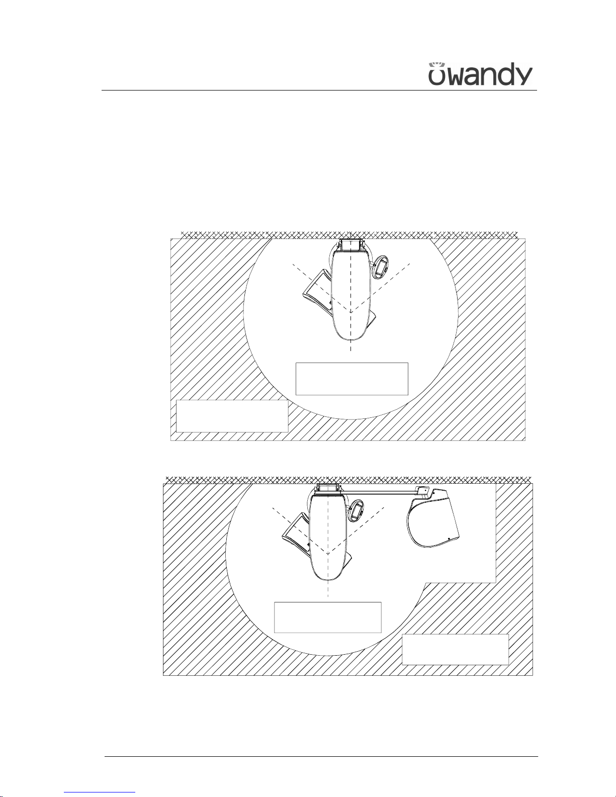
Although the dose supplied by dental X-ray units is quite low and
distributed on a fairly small surface, the operator must adopt the
precautions and/or suitable protection for the patient and himself,
during the execution of radiography. It is advisable to control the X-ray
emission from a protected area, by means of a remote control. If it is
necessary to operate near the patient, stay as far as the remote control
cable allows, or at least 1.5m (4.9 ft) both from the X-ray source and from
the patient, as shown in Figure 1 and Figure 2.
Minimum distance from
X-ray source 1.5m
Protected area
Figure 1 - Panoramic version
Minimum distance from
X-ray source 1.5m
Protected area
Figure 2 - Cephalometric version
Page 11
USER'S MANUAL
Safety information
I-Max Touch (110-120V) (Rev. 0)
6
WARNING: PRECAUTIONS WHILE USING LASER CENTRING
DEVICES:
• Always keep the room well lit.
• Do not look into the output windows of laser centring units.
• Do not stare at the reflections of laser pointers.
• Instruct the patient to keep his/her eyes closed as long as the laser
pointers are active.
• Before starting an examination, the patient must remove earrings,
glasses, necklaces and whatever else could reflect the laser beam or
be impressed on the radiographic image.
• Do not clean the openings of laser centring devices with tools that
could modify the optics. Any cleaning must be performed only by
authorised technicians
.
Operations other than those indicated could cause the ejection of
dangerous non-ionising radiation.
WARNING:
The USB port on the keyboard MUST NOT
be used with an external Hard
Disk with own mains connection. It has to be used only with USB Pen
Drives.
NOTE:
Patient environment is defined as a distance of at least 1.5 m (4.9 ft) from
the patient.
If the PC is positioned outside the patient environment when in use, the
PC has to be compliant to IEC 60950, otherwise the PC must complies
with medical standard IEC 60601-1.
NOTE:
When the unit is switched on, do not move the rotating arm or the
tube-head.
*
*
Page 12

USER'S MANUAL
Safety information
(Rev. 0) I-Max Touch (110-120V)
7
2.2 Environmental risks and displacement
In some of its parts, the device contains materials and liquids that, at the
end of the lifespan of the unit, must be disposed of at the appropriate
disposal centres.
In particular, the device contains the following materials and/or
components:
• Tube-head: dielectric oil, lead, copper, iron, aluminium, glass,
tungsten.
• Control Panel
: iron, copper, aluminium, glass-resin, non-
biodegradable plastic material packaging.
• Column, rotating arm and extensions: iron, lead, aluminium,
copper, glass-resin, and non-biodegradable plastic material.
Page 13
USER'S MANUAL
Safety information
I-Max Touch (110-120V) (Rev. 0)
8
2.3 Symbols used
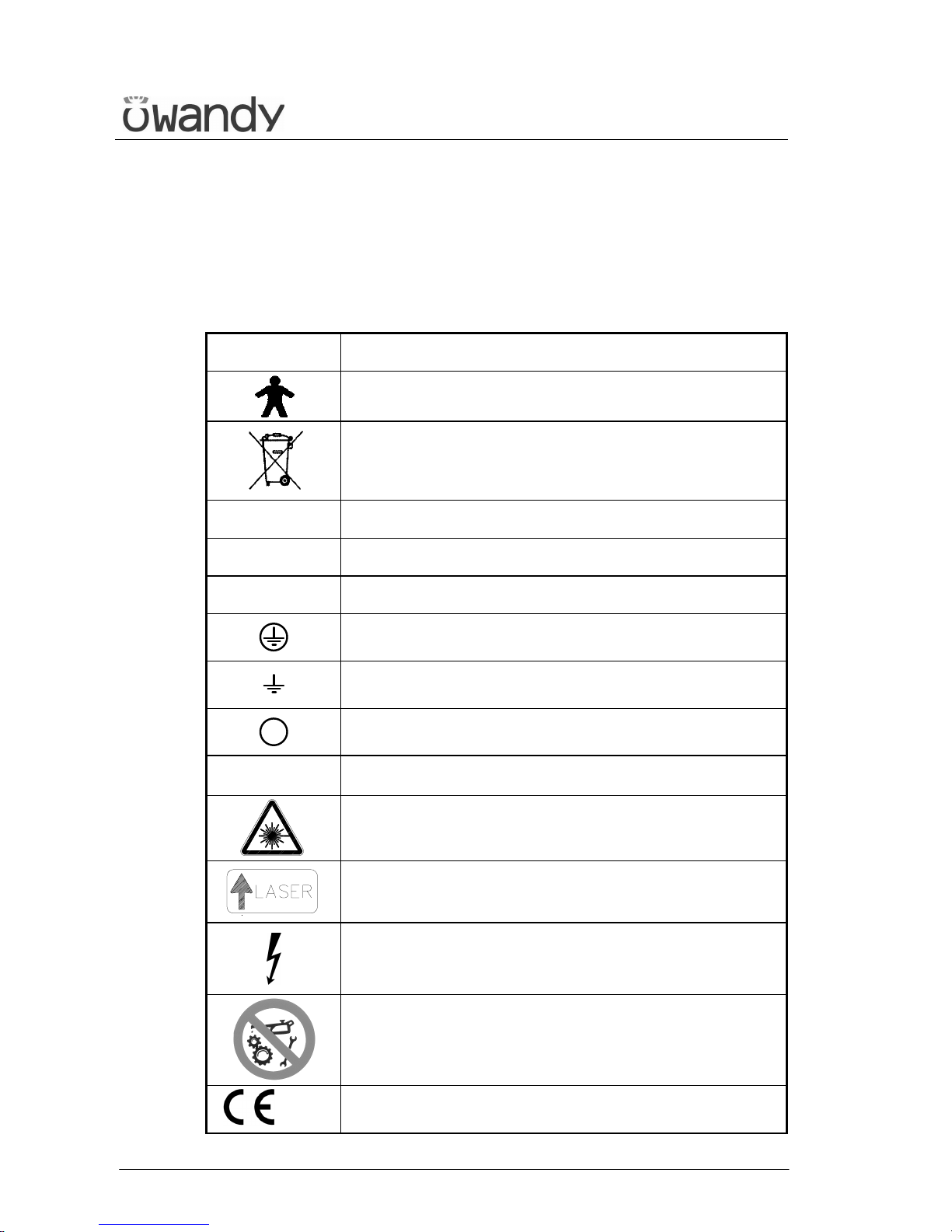
In this manual and on the I-Max Touch itself, apart from the symbols
indicated on the control panel, the following icons are also used (see
Chapter 6):
Symbol Description
Device with type B applied parts
In some of its parts, the device contains materials and
liquids that, at the end of the lifespan of the unit, must
be disposed of at the appropriate disposal centres
∼∼∼∼
A.C.
N
Connection point to the neutral conductor
L
Connection point to the line conductor
Protection earthing
Operation earthing
OFF; device not connected to the mains
ON; device connected to the mains
Laser
Laser source output
Dangerous voltage
Moving parts MUST NOT be cleaned or lubricated
0459
Conformity to the EC 93/42 Directive
Page 14
USER'S MANUAL
Cleaning and disinfection
(Rev. 0) I-Max Touch (110-120V)
9
3. CLEANING AND DISINFECTION
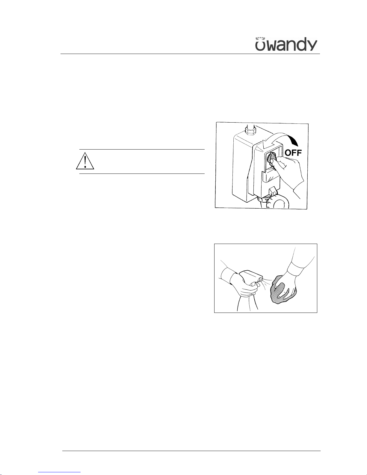
In order to guarantee a good level of hygiene and cleaning, it is necessary
to respect the following procedures.
WARNING:
Disconnect the unit from the mains
before performing any cleaning.
Do not let water or other liquids enter the unit, as these could cause
corrosion or short-circuiting.
Use only a wet cloth and a mild
detergent to clean the painted
surfaces, the accessories and the
connection cables, and then wipe
with a dry cloth; do not use
corrosive, abrasive solvents
(alcohol, benzine, trichloroethylene).
The disposable bite protective sleeve and the ear centring devices of
the cephalostatus must be replaced after each examination in which
they have been used.
Thoroughly clean the chin support, resting handles, nose-rest and temple
clasps group any time these are used.
The chin support, resting handles, nose-rest and temple clasps group
should be disinfected (when considered necessary) with a solution of 2%
glutaraldehyde.
Page 15
USER'S MANUAL
Description
I-Max Touch (110-120V) (Rev. 0)
10
4. DESCRIPTION
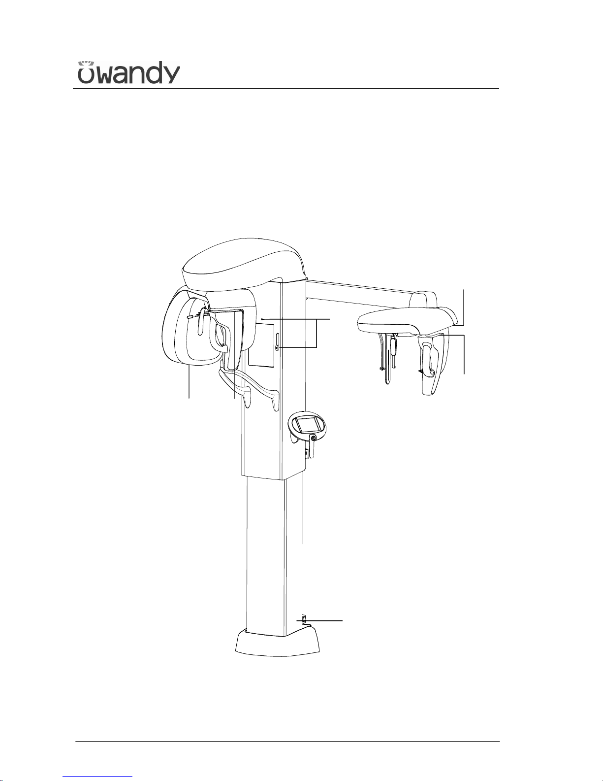
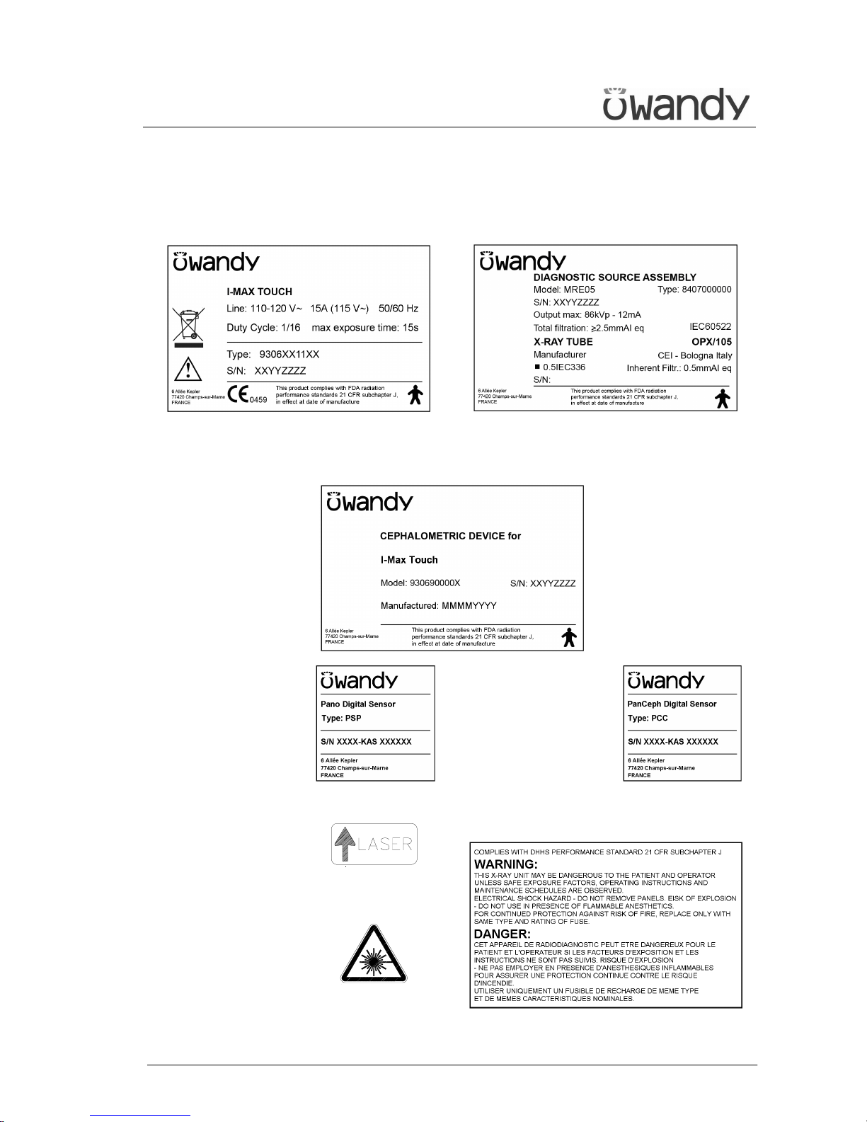
4.1 Identification labels and laser labels
4
3
6, 7
1, 8
2
5
Page 16
USER'S MANUAL
Description
(Rev. 0) I-Max Touch (110-120V)
11
1
I-Max Touch
identification label
2
Tube-head
identification label
3
CEPHALOMETRIC device
identification label
4
PANO
Digital Sensor
identification label
5
PANCEPH.
Digital Sensor
identification label
6
(N° 2) Spot Laser
identification label
7
(N° 2) Laser
symbol label
8
WARNING label
Page 17

USER'S MANUAL
Description
I-Max Touch (110-120V) (Rev. 0)
12
4.2 Functions, models and versions
The I-Max Touch, produced by Owandy, is a complete panoramic system,
which enables to perform all X-rays commonly necessary in dental field
(except for endoral X-rays).
In some versions, certain examination modes are not available but the
device (thanks to its computerised control system) can be expanded and
updated with new releases, directly at the Dentist premises.
The basic version performs Panoramic, Emi-panoramic, Reduced dose
Panoramic, Frontal dentition, Improved orthogonality Panoramic Sinus
and TMJ examinations.
Optional functions enable the system to perform the following additional
examinations:
• CEPH
Allows you to carry out the following examinations:
− CEPH exam in different formats
− CARPUS exam.
4.2.1 Basic version
The basic version enables to perform the following examinations:
• Panoramic Adult or Child, with 3 Sizes and 3 Types of Biting for a
total of 18 combinations in Automatic selection; in manual selection
it is possible to select high voltage between 60kV and 86kV, in 2kV
steps and anodic current from 6 mA to 10 mA in 1 mA steps.
• Sinus enables to perform images of the paranasal sinuses with front
projection (postero/anterior).
• TMJ mouth closed/open in lateral projection.
• The right or left Emi-panoramic is used when the patient is known to
have a problem only on one side of the arch, in order to reduce the
radiation.
• The reduced dose Panoramic reduces the dose radiated on the
dentition by excluding the TMJ's ascending rami from the exams.
• The frontal dentition enables to perform examinations of the front
part (roughly from canine to canine).
• The Panoramic with improved orthogonality reduces the overlap of
the teeth, thereby improving the diagnosis of interproximal decay.
Page 18

USER'S MANUAL
Description
(Rev. 0) I-Max Touch (110-120V)
13
4.2.2 Version with cephalometric device
The version with cephalometric device allows you to perform the following
examinations:
• Panoramic, Sinus, TMJ, Emi-panoramic, Reduced dose Panoramic,
Frontal dentition and Improved orthogonality Panoramic, Adult and
Child, with the same characteristics described for the base version.
• Digital Cephalometry for Adult and Children with 3 Sizes each.
Within each combination, it is possible to select an examination in
Hight or Normal Resolution, for a total of 12 combinations in
Automatic selection. In Normal Resolution, the examination is carried
out with a lower scanning time, allowing a further reduction of the
dose. In Manual selection it is possible to vary the Hight Voltage from
60kV to 86kV, with 2kV steps, the anodic current from 6mA to 12mA
with 1mA steps. The positioning of the sliding primary collimator, the
secondary collimator and the Digital Sensor (inside the relative
sensor holder) is automatic according to the selected format
projection. The Soft Tissues Filter is motorized, to obtain the best
possible emphasis of the face profile.
• Examination to evaluate the bone growth (Carpus) only Child with 3
Sizes. It is possible to select an examination in High or Normal
Resolution, for a total of 6 combinations in Automatic selection. In
Normal Resolution, the examination is carried out with a lower
scanning time, allowing a further reduction of the dose. In Manual
selection it is possible to vary the tension from 60kV to 86kV, with
2kV steps, the anodic current from 6mA to 12mA with 1mA steps.
The positioning of the sliding primary collimator, the secondary
collimator and the Digital Sensor (inside the relative sensor holder) is
automatic
The values of the exposure factors shown in the tables of paragraph 6.13,
set as default, are for guidance only.
The real adjustment of these values depends on user’s trade off between
expose dose and image contrast.
Image processing should help you getting the best contrast.
Page 19
USER'S MANUAL
Technical characteristics
I-Max Touch (110-120V) (Rev. 0)
14
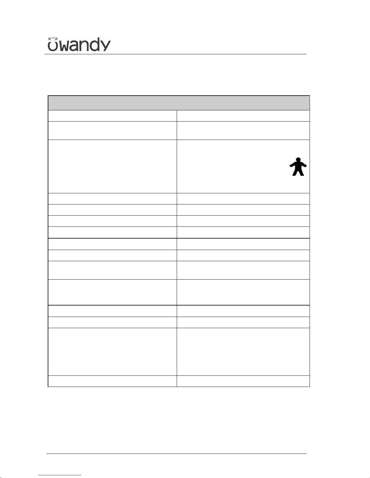
5. TECHNICAL CHARACTERISTICS
General features
Type I-Max Touch
Manufacturer OWANDY
Champs sur Marne, France
Class Class II B for European Directive
for Medical Devices 93/42
Class II for Canadian MDR
Class I with type B applied parts
according to IEC 60601-1
Class II according to 21CFRsubchapter J
Protection degree IPX0 standard device
Rated line voltage
110-120 V∼
Line frequency 50/60 Hz
Maximum line current
15 A @ 115 V∼ 50/60 Hz
Power consumption
1.7 kVA @ 115 V∼ 50/60 Hz
Protection fuse (F1) 15 A T
Protection fuse (F2) of switching power
supply
3 A T
HF generator board protection fuses F1: 10 A F
F2: 5 A HF
F3: 2 A T
Line voltage regulation
< 3 % at 99 V∼
Rated output voltage (kVp) 60 ÷ 86 kV
p,
with 2 kVp steps
Anodic current 6 ÷ 10 mA, with 1 mA steps for PAN, TMJ,
and Sinus
6 ÷ 12 mA in 1 mA steps for Ceph (up to
76 kVp)
6 ÷ 10 mA in 1 mA steps for Ceph (from
78 kVp to 86 kVp)
Sensor cover additional filtration 0.5 mm Al eq @ 70 kVp
Page 20
USER'S MANUAL
Technical characteristics
(Rev. 0) I-Max Touch (110-120V)
15
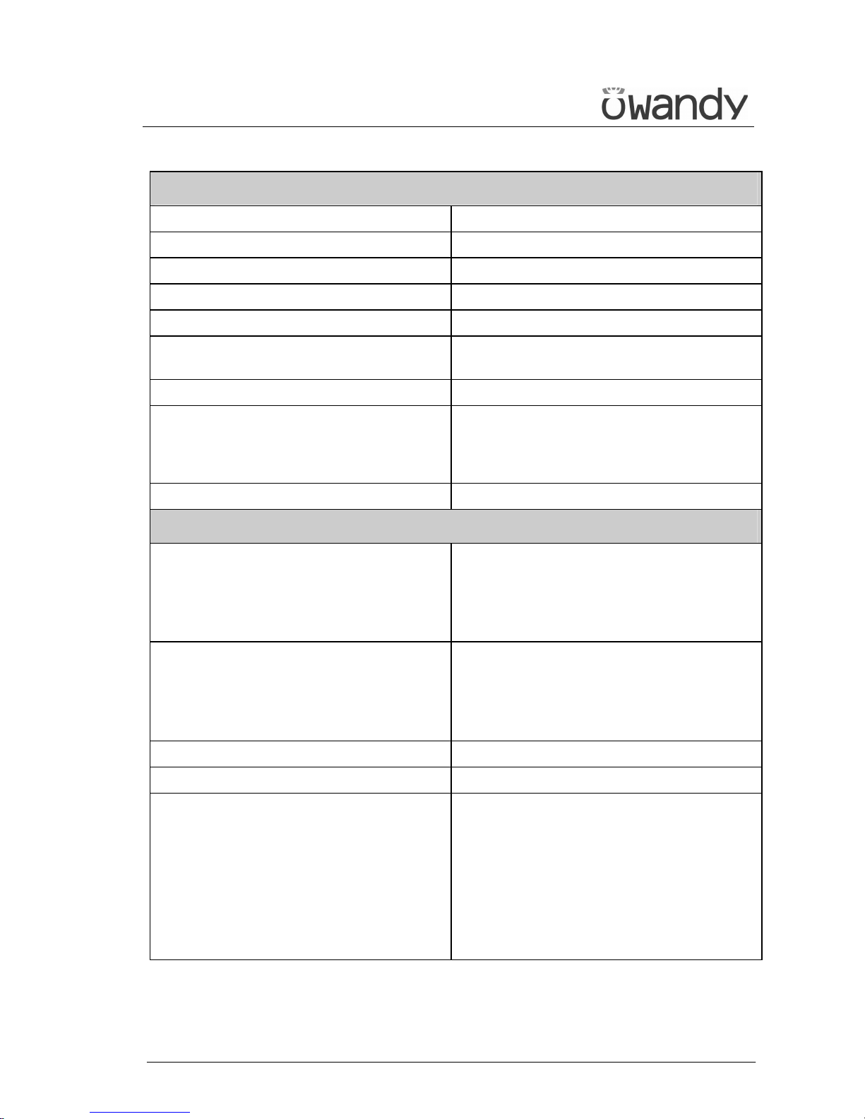
Exposure times
Panoramic (PAN) 13.8 s PAN Adult / 13.4 s PAN Child
EmiPanoramic 7.4 s Adult / 7.3 s Child
Improved orthogonality Panoramic 11.9 s Adult / Child
Reduced dose Panoramic 11.4 s Adult / Child
Frontal Dentition 4.4 s Adult / Child
TMJ mouth closed/open 2.44 s per image for left and right joint in
open and closed condition, total of 9.7 s
Sinus P/A projection 9.4 s
Cephalometry (Ceph) Exposure time variable according to the
type of resolution and format selected.
Minimum 4.5 s (18x22 nR), maximum
15 s (30x22 hR)
Exposure time accuracy ± 10 %
Examination modes
Examination selection
• Automatic selection for Adult and
Child, 3 Sizes
• 3 biting modes (in Panoramic)
• Manual selection
• Collimator with automatic positioning
Panoramic
• Standard Panoramic
• Half Panoramic L/R
• Improved orthogonality Panoramic
• Reduced dose Panoramic
• Frontal dentition
TMJ (Temporal Mandibular Joint) TMJ open and closed mouth
Sinus Sinus P/A projection
Cephalometry and Carpus
• Normal resolution cephalometry in
Latero-Lateral or Antero-Posterior
projection (different formats)
• High resolution cephalometry Latero-
Lateral or Antero-Posterior projection
(different formats)
• Normal and High Resolution Carpus
exam
• Motorized Soft Tissue Filter.
Page 21
USER'S MANUAL
Technical characteristics
I-Max Touch (110-120V) (Rev. 0)
16
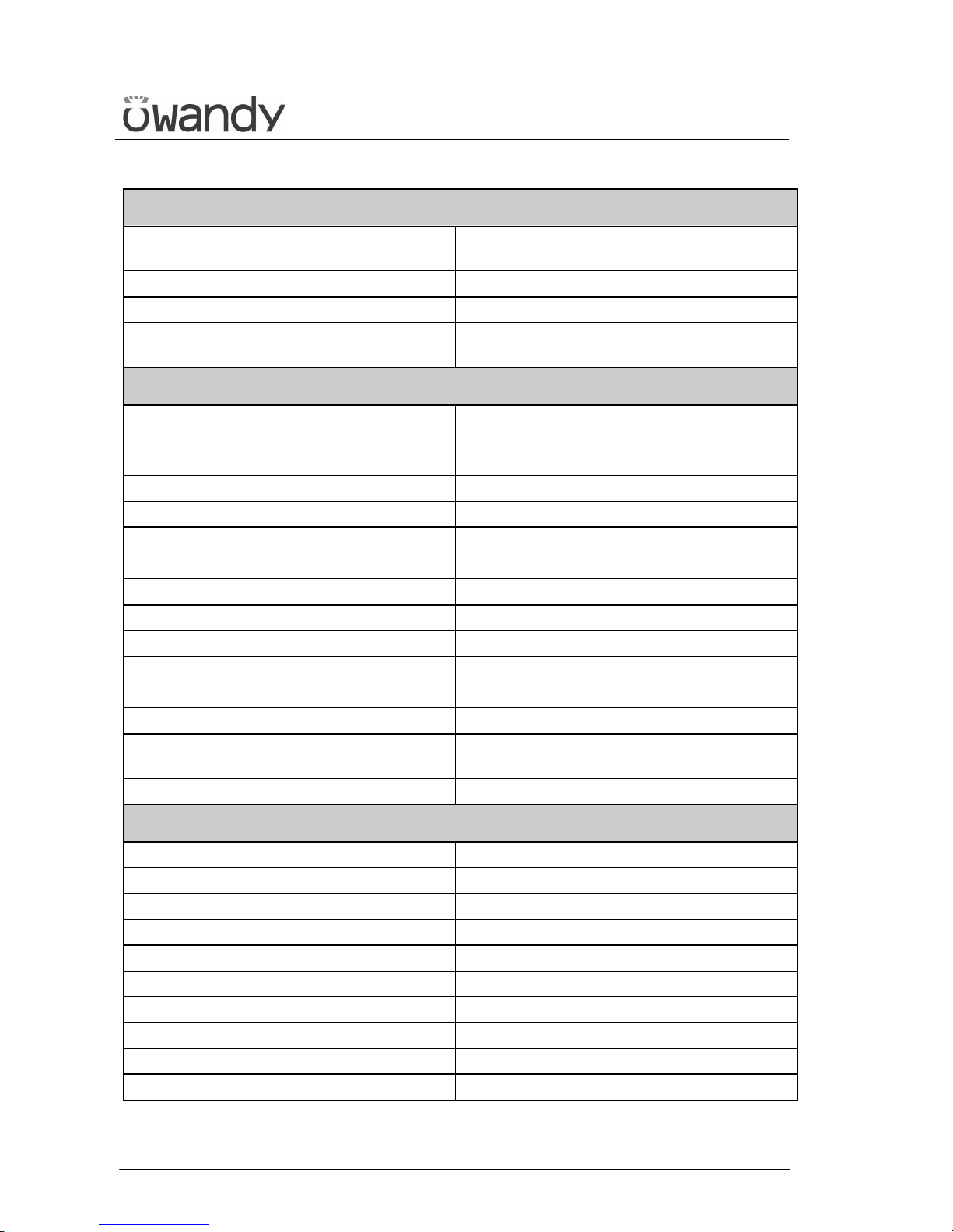
Image magnification
Standard Panoramic
Constant over dentition part:
1 : 1.23 Adult - 1 : 1.25 Child
TMJ open/closed mouth, 4 images 1 : 1.20 (nominal)
Sinus 1 : 1.22 (nominal)
Ceph
1 : 1.10 (on the sagittal medial plane in
LL projection)
Tube-head characteristics
Model MRE 05
Manufacturer
Villa Sistemi Medicali S.p.A.
20090 Buccinasco (MI) Italia
Maximum tube voltage 86 kVp
kVp accuracy ± 8 %
Maximum anodic current 12 mA
Anodic current accuracy ± 10 %
Duty cycle 1 : 16
Nominal power 1.032 kW (86 kVp - 12 mA)
Total filtration 2.5 mm Al eq. @ 70 kVp
HVL (Half value layer) > 3.1 mm Al eq. @ 86 kVp
Transformer insulation Oil bath
Cooling By convection
Leakage radiation at 1 m
< 0.5 mGy/h @ 86 kV
p
- 12 mA - 3 s duty
cycle 1/16
Tube-head maximum thermic capacity 310 kJ
X-ray tube characteristics
Manufacturer CEI Bologna (Italy)
Type OPX 105
Nominal focus size 0.5 IEC 60336
Inherent filtration 0.5 mm Al eq.
Anode tilt 5°
Anode material Tungsten
Nominal maximum voltage 105 kVp
Filament max current 4 A
Filament max voltage 8 V
Anode thermal capacity 30 kJ
Page 22
USER'S MANUAL
Technical characteristics
(Rev. 0) I-Max Touch (110-120V)
17
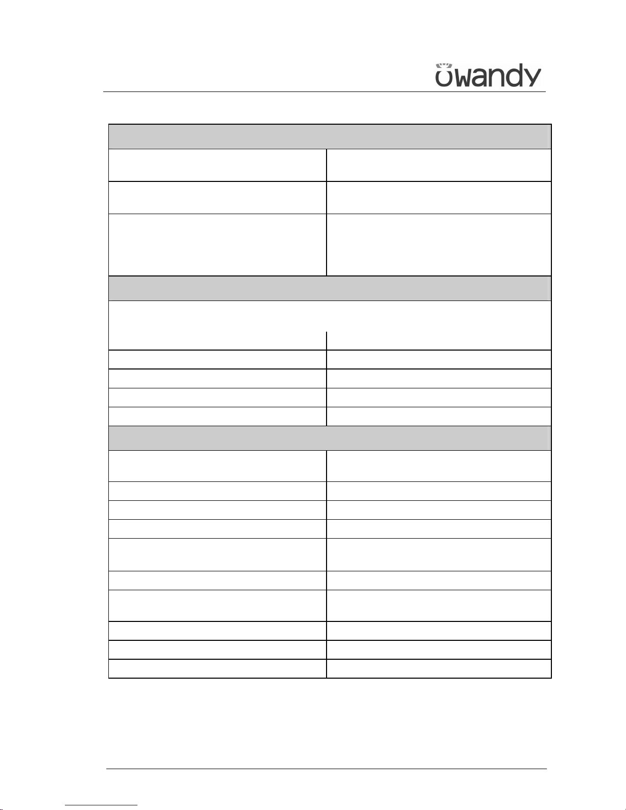
Digital Sensor
Sensible area (H x L)
• PAN sensor: 146 x 6 mm
• PANCEPH sensor: 220 x 6 mm
Pixel dimensions
48 µm, 96 µm in binning 2x2 (PAN and
PANCEPH HR), 144 µm CEPH nR
Pixel (H)
NOTE:
Number of horizontal pixels depends on
the exam and resolution on CEPH.
• PAN: 1536
• CEPH: 1536 in nR, 2304 in HR
Laser centring devices
2 laser beams are used for the patient positioning; beams align mid Sagittal and
Frankfurt planes (please refer to relevant paragraphs for detailed explanation).
Wave length 650 nm
Divergence 12.5 mRad
Optical power on the working surface < 0.5 mW
Laser class Class 1 according to IEC 60825-1+A1+A2
DNRO in 30s application period 0.05m
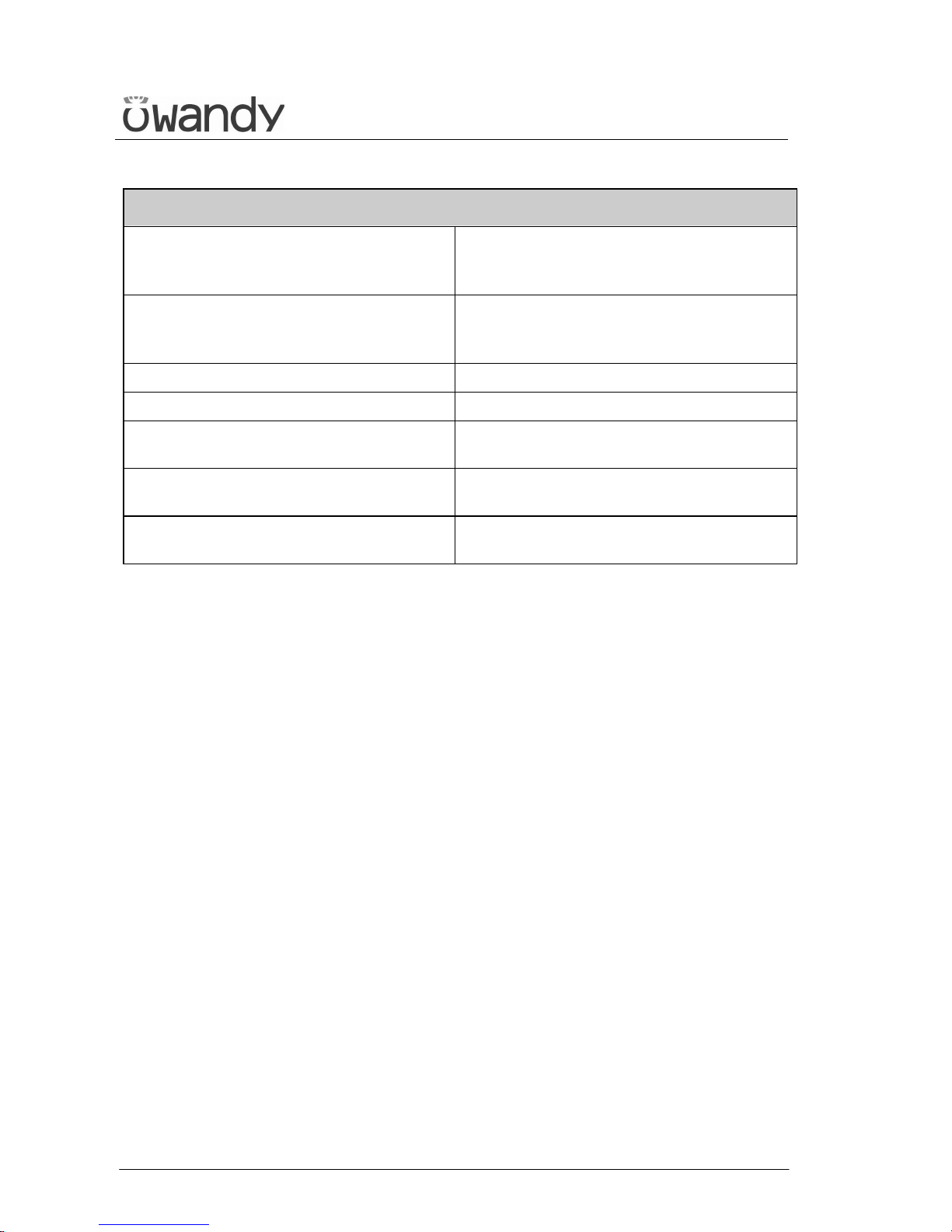
Mechanical characteristics
Focus-receptor distance (PAN, TMJ and
Sinus)
50 cm (19.7")
Focus-receptor distance (CEPH) 165 cm (65")
Telescopic motorised column run 85 cm (33.5")
Maximum total height 245 cm (96.5")
Weight
• 161 kg (354 lbs) base version
• 186 kg (409 lbs) version with Ceph
Column weight 87 kg (192 lbs)
Weight of arm support, rotating arm and
tube head
74 kg (163 lbs)
CEPH arm 25 kg (55 lbs)
Legs (optional) 30 kg (66 lbs)
Sensor holder weight 2 kg (5 lbs)
Page 23
USER'S MANUAL
Technical characteristics
I-Max Touch (110-120V) (Rev. 0)
18
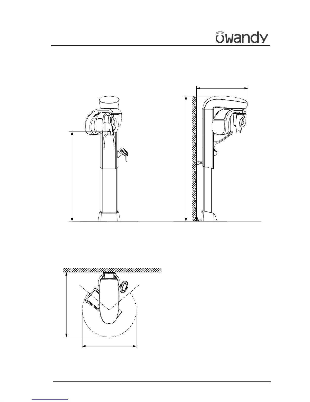
Working conditions
Minimum room size (please refer to the
Service Manual)
• 130x120 cm (51.2"x47.2") without
CEPH
• 145x202 cm (57"x78.7") with CEPH
Recommended room size (please refer to
the Service Manual)
• 130x140 cm (51.2"x55.1") without
CEPH
• 160x222 cm (63"x86.6") with CEPH
Maximum working temperature range
+ 10° ÷ + 40°
Relative working humidity (RH) range
30% ÷ 75%
Temperature range for transport and
storing
- 20° ÷ + 70°
Humidity range for transport and
storing
< 95% without condense
Minimum atmospheric pressure for
transport and storing
630 hPa
Page 24
USER'S MANUAL
Technical characteristics
(Rev. 0) I-Max Touch (110-120V)
19
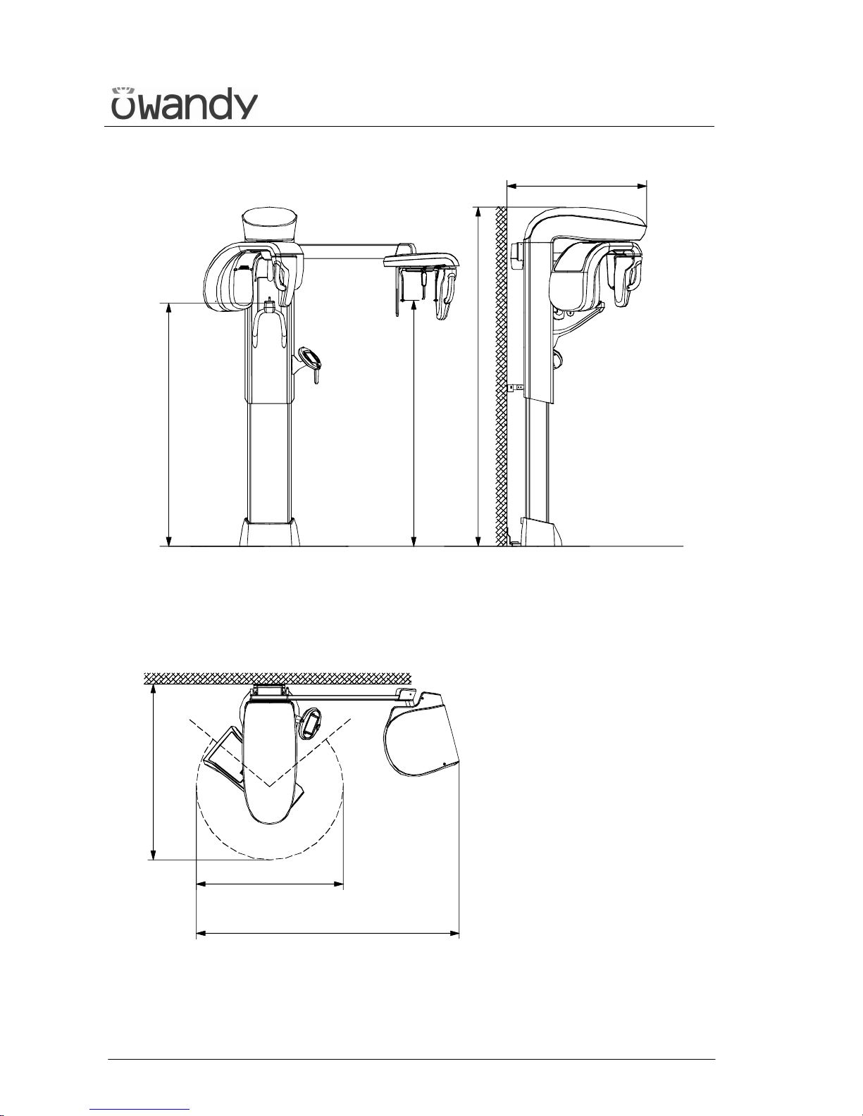
5.1 Dimensions
1260 (49,60")
Ø 1040 (40,95")
905 (35,63") 1755 (69,10")
÷
÷
1600 (63,00") 2450 (96,46")
1009 (39,74")
Ø 1140 (44,88")
with free standing base
Figure 3 – I-Max Touch dimensions
Base version
Page 25
USER'S MANUAL
Technical characteristics
I-Max Touch (110-120V) (Rev. 0)
20
1260 (49,60")
Ø 1040 (40,95")
905 (35,63") 1755 (69,10")
÷
÷
1600 (63,00") 2450 (96,46")
1009 (39,74")
927 (36,50") 1777 (69,96")
÷
1910 (75,20")
Ø 1140 (44,88")
with free standing base
1970 (77,56") with free standing base
Figure 4 – I-Max Touch dimensions
Version equipped with cephalometric unit
Page 26
USER'S MANUAL
Technical characteristics
(Rev. 0) I-Max Touch (110-120V)
21
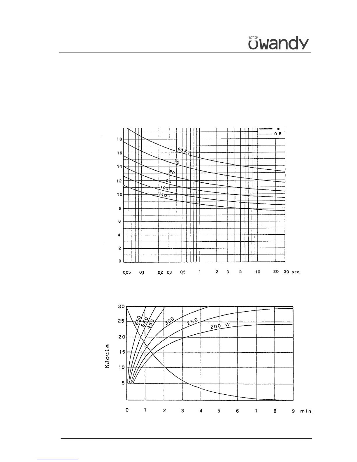
5.2 Loading curve of the tube and cooling curve of the
anode
Tube "CEI - OPX/105" (0.5 IEC 60336)
Load
Anode cooling curve
Page 27
USER'S MANUAL
Technical characteristics
I-Max Touch (110-120V) (Rev. 0)
22
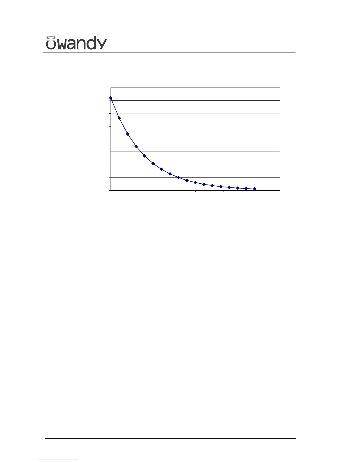
Tube-head heating and cooling curve
0
50
100
150
200
250
300
350
400
0 100 200 300 400 500 600
min
E[kJ]
Page 28

USER'S MANUAL
Technical characteristics
(Rev. 0) I-Max Touch (110-120V)
23
5.3 Applied safety regulations
The I-Max Touch complies with the following standards:
0459 The symbol CE grants that I-Max Touch complies with
directives 93/42 for medical devices issued by the
European Community.
• Canadian Medical Device Regulations
• 21 CFR Subchapter J
• General safety:
IEC 60601-1:1988 + A1:1991 + A2:1995
IEC 60601-1-4:1996 + A1:1999
IEC 60601-2-7:1998
IEC 60601-2-28:1993
IEC 60601-2-32:1994
• Electromagnetic compliance:
IEC 60601-1-2:2001
• Protection against radiation:
IEC 60601-1-3:1994
IEC 60825-1:1993 + A1:1997 + A2:2001
Classification
I-Max Touch is an electro-medical X-ray device belonging to Class 1 and
Type B as per classification IEC 60601-1, foreseen for a continuous
working at intermittent load.
According to CE 93/42 directive for medical devices, the equipment
belongs to class II B.
According to Canadian MDR, the equipment belongs to class II.
According to FDA 21 CFR, the equipment belongs to class II.
Page 29
USER'S MANUAL
Technical characteristics
I-Max Touch (110-120V) (Rev. 0)
24
5.4 Note on constant magnification for Panoramic and
TMJ (mouth open/closed) examinations
NOTE:
The I-Max Touch is based on a standard dentition and ascending rami
shape.
This shape, based on statistical studies, establishes a form for the
dentomaxillofacial complex, adopted as "standard".
The I-Max Touch follows a rototranslation path which maintains constant
the magnification factor stated in the Technical Characteristics of each
type of exam along this "standard" shape only along the dentition area.
The patient’s anatomy can differ significantly from the statistical model,
so the magnification factor is not maintained and can be different from
the value stated. Based on his experience and competence, the user has
to judge this variation.
IN ANY CASE, THE RADIOGRAPHY IMAGES CANNOT BE USED TO
PERFORM CALCULATIONS OF DISTANCES, ANGLES ETC. ON THE
IMAGE.
*
Page 30
USER'S MANUAL
Technical characteristics
(Rev. 0) I-Max Touch (110-120V)
25
5.5 Measurement method of technical factors
(paragraph for authorised personnel)
WARNING:
These measurements require the removal of the HF group covers; this
means to gain access to internal parts where high voltage are normally
present.
For the measurement of the exposure parameters with the invasive
method, please follow the procedure described in the Service manual.
WARNING:
During the panoramic examination, the set value of kV and tube current
varies according to a fixed curve, to compensate the variations in
absorption by the patient's tissues; in this way, it is possible to obtain a
good uniformity of the image contrast. In particular, the chosen value is
lowered during the initial phase, and increased on the canine/incisor
zone, in order to compensate the effect of greater attenuation owing to
the spine.
The value displayed during the panoramic examination corresponds to
the one chosen by the user, while the real value can be different; this fact
must be considered if the exposure parameters are checked using
standard diagnostic mode.
The accuracy of the exposure parameters kV and mA, stated in the
Technical Data section, refers to the accuracy compared with the
instantaneous value set by the system.
In any case, the manufacturer guarantees that the accuracy of the
exposure parameters is always in compliance with the international
standards for the safety of medical devices IEC 60601-1. In particular, in
accordance with IEC 60601-2-7, the maximum deviation (including the
correction and instrumental doubt) is less than or equal to ±10 for kV,
while for tube current it is less than or equal to ±15%.
Page 31
USER'S MANUAL
Technical characteristics
I-Max Touch (110-120V) (Rev. 0)
26
5.6 Verification method of technical factors
(paragraph for authorised personnel)
The exposure parameters (kV, time and dose) can be checked using the
so-called "non-invasive method".
WARNING:
The device collimator gives a narrow X-ray beam.
Measurements taken with a non-invasive instrument and a narrow beam
can be difficult and/or unreliable; it is therefore necessary to use a
special probe with a reduced sensitive area.
It may be helpful to use a fluorescent screen to locate the X-ray beam,
and consequently position the probe of the kV meter.
The procedure to measure the exposure parameters by a non-invasive kV
meter is the following:
1. With the unit switched ON, be either in Anatomic or Manual mode,
press the "Anatomic/Manual" mode indicator until it turns green and
displays "S" , then press the "Test function" (5)
key to enter the exposure verification mode, the display shows:
x x k V x x m A x x . x s
E M I S S I O N P R O G R A M
WARNING:
The following operations involve the emission of X-rays, so the
Authorised Technician must pay the greatest attention and respect the
protection regulations in force in that country.
NOTE:
This program allows you to carry out the measuring of the exposure
parameters with the tube-head arm in a fixed position (not rotating)
without variation due to spine compensation.
2. Place the measuring instrument.
*
Page 32
USER'S MANUAL
Technical characteristics
(Rev. 0) I-Max Touch (110-120V)
27
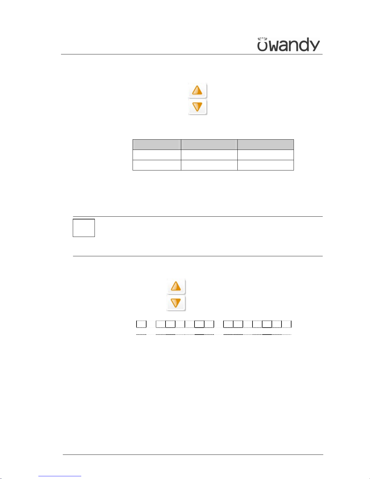
3. The KV and mA parameters can be modified by pressing the increase
key and the decrease key of the KV and mA on the display.
The parameters can vary within the limits shown in the following
table:
Parameter Minimum value Maximum value
kV 60 86
mA 6 12
Table 1
4. Perform an exposure; technical factors can be read on the measuring
instrument.
NOTE:
The performance is guaranteed only if the measurement of kV and time is
done with the invasive method, due to the fact that the non-invasive
method may introduce errors for instruments tolerance or wrong
measurement condition.
5. To end the control program, press any key other than the increase
and decrease keys ; the display will indicate:
x x k V x x m A x x . x s
P A N O R A M I C - S T D
and the unit will return to standard mode.
*
Page 33
USER'S MANUAL
General instructions for use
I-Max Touch (110-120V) (Rev. 0)
28
6. GENERAL INSTRUCTIONS FOR USE
6.1 Control panel - description and functions
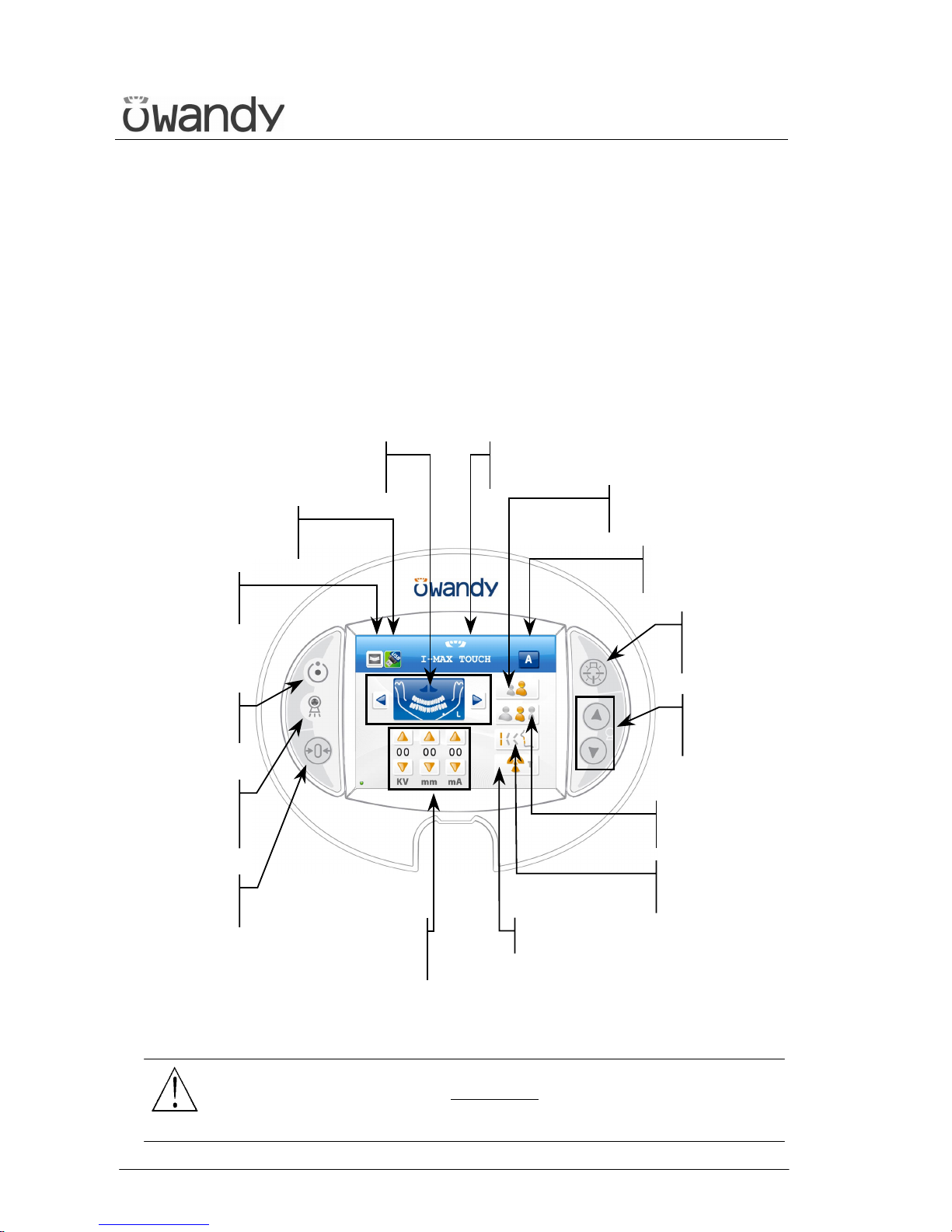
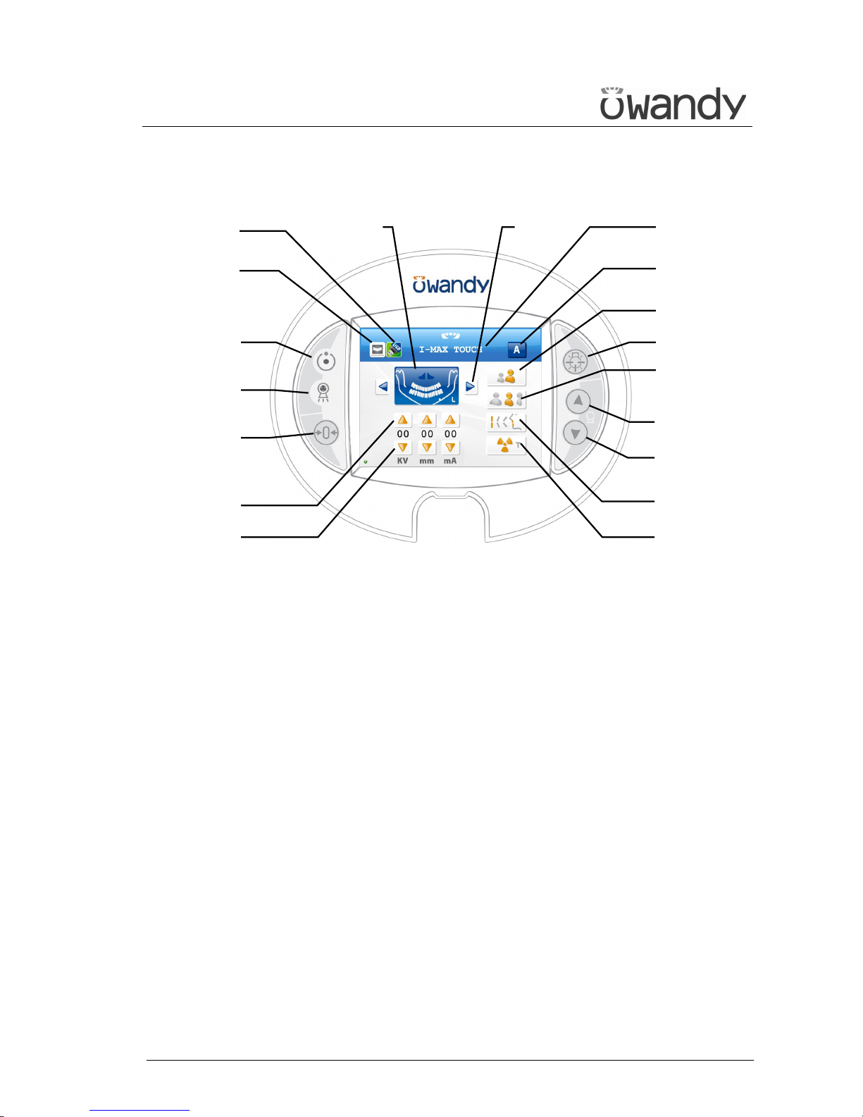
The I-Max Touch keyboard is divided into function areas, plus a display
to view the operative messages and error signals.
The next figure shows a general view of the control interface, while details
on each functional area are provided in the following pages.
Figure 5
WARNING:
The USB port on the keyboard MUST NOT
be used with an external Hard
Disk with own mains connection. It has to be used only with USB Pen
Drives.
Light signalling
"X-rays in
p
rogress"
"Centring/Patient
Entrance" button
"Exposure
Parameters
Variation" button
Light signalling
"Ready for X-rays"
"Exam mode
selection" buttons
"Centring
devices ON"
button
Messages display
"Test" button
"Adult/Child
selection" button
"Size Selection"
button
"Type of biting
selection" button
"Column
movement"
button
"Automatic/Manual
mode" indicator
"USB Pen Drive"
button
"View acquired
image" button
Page 34
USER'S MANUAL
General instructions for use
(Rev. 0) I-Max Touch (110-120V)
29
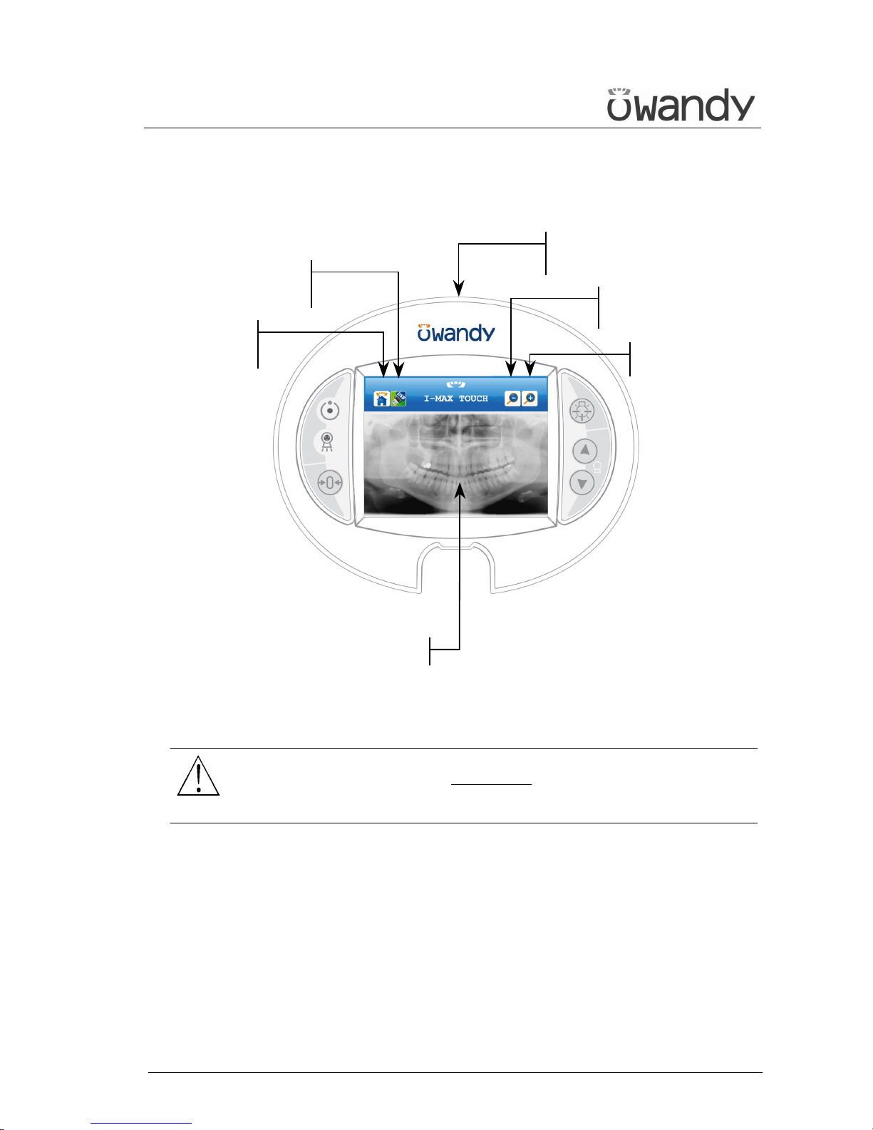
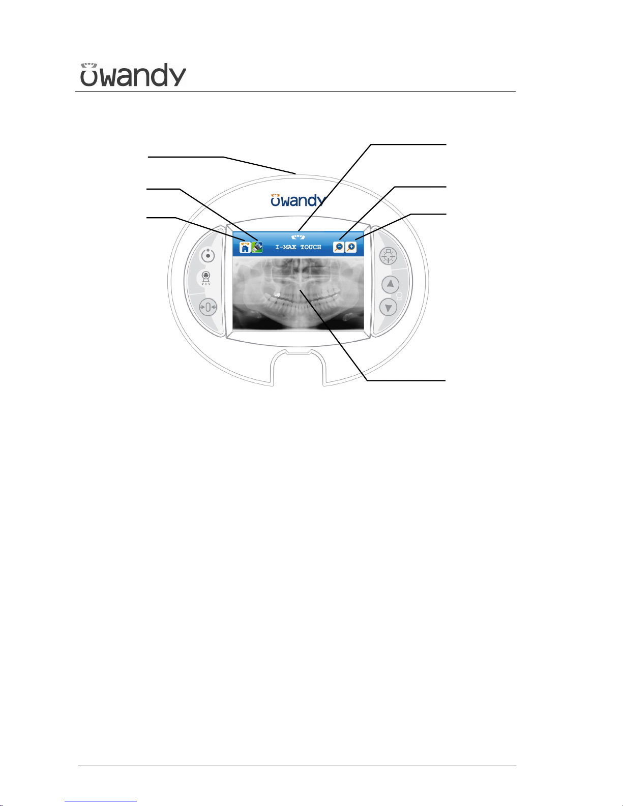
The next figure shows a general view of the display of the acquired image,
details on each functional area are provided in the following pages.
Figure 6
WARNING:
The USB port on the keyboard MUST NOT
be used with an external Hard
Disk with own mains connection. It has to be used only with USB Pen
Drives.
A
cquired image
"USB Pen Drive"
button
"Return to main
menu" button
"Zoom out" button
"Zoom in" button
USB port for
p
en drive
Page 35
USER'S MANUAL
General instructions for use
I-Max Touch (110-120V) (Rev. 0)
30
The "Centring/Patient Entrance" button
is used to:
- start/stop the start examination
procedures
- bring the rotation arm to the
patient entrance position at the end
of the exam.
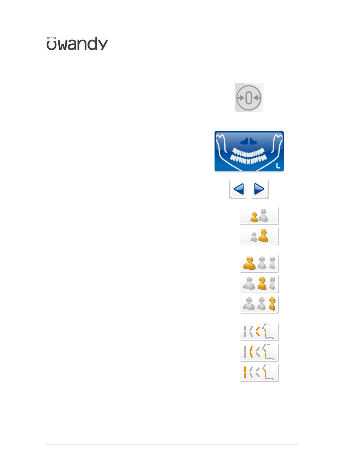
The "Examination Selection Mode"
takes place by means of three keys: the
first one, the main button, helps select
the exam mode between Panoramic,
TMJ, Sinus, and Cephalometric.
The other two, identified by the arrows,
help navigate within the exams of each
mode.
It is possible to select the anatomic
mode examinations (anatomic
selection), using prefixed exposure
values.
This kind of selection enables to choose
between Adult/Child, each with three
different sizes (small, medium, large).
Child
Adult
Large
Medium
Small
The Panoramic mode enables to select
the patient's type of biting between:
protruded, standard or retracted, as
indicated within the button.
The arch selection does not influence
the values of kV and mA but acts on
the position of the focus layer.
Protruded
Standard
Retracted
Page 36
USER'S MANUAL
General instructions for use
(Rev. 0) I-Max Touch (110-120V)
31
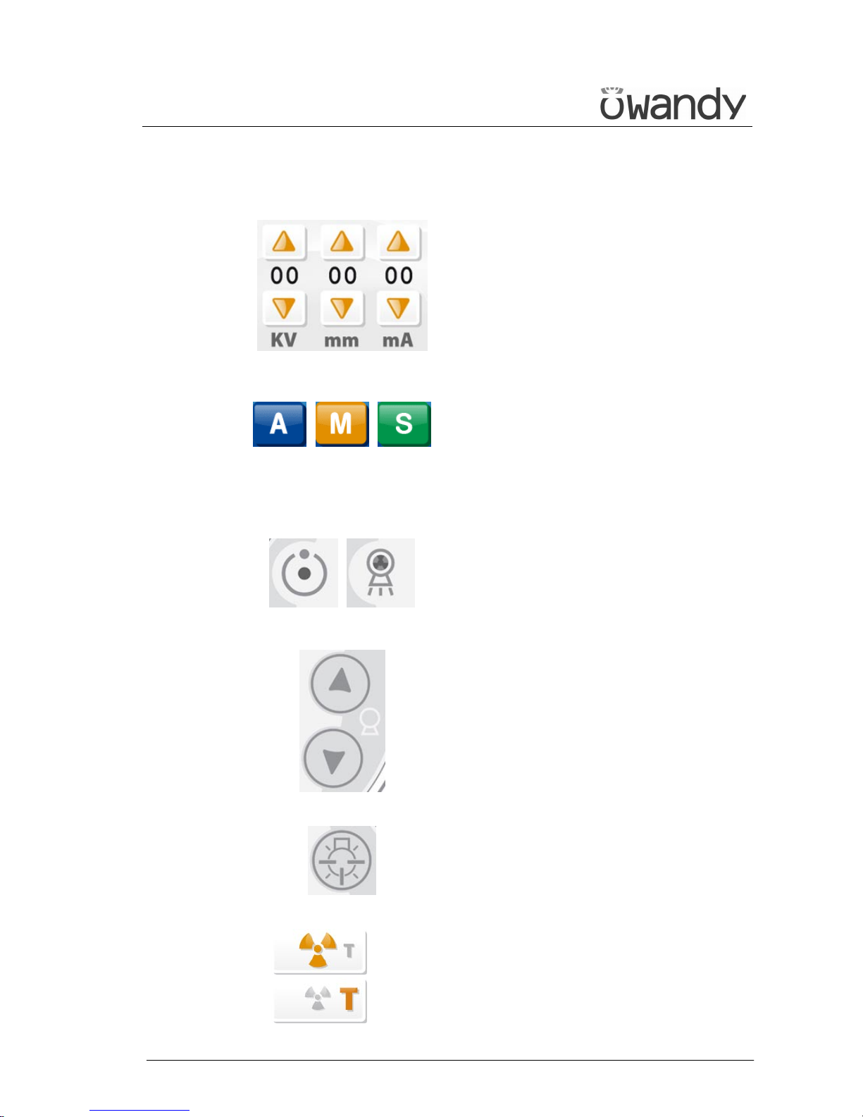
Furthermore there is the possibility to
manually select the exposure
parameters; in this case, it is possible
to set the parameter with the desired
value.
The parameters available are: kV and
mA (Soft Tissue Filter position, mm,
only in cephalometry).
When the exposure parameters are
changed manually, the mode indicator
switches from "Anatomic" to "Manual".
Return to "Anatomic mode" using the
main programme selection button. By
holding the indicator for more than
1 second the special mode is activated
and the indicator changes colour. In
special mode modified exposure
parameters can be stored or exposure
verification tests can be performed.
There are two light indicators; the first
one on the top indicates the condition
"Machine Ready", indicating the user
that by pressing the X-ray button key
once more, X-rays emission will start;
the second indicates the effective
emission of X-rays.
The movement of the column is
controlled by the appropriate keys.
The speed has two set values.
The movements are enabled during
equipment setting.
The key "Luminous centring device"
helps turn ON/OFF the laser centring
devices that allow the correct
positioning of the medial-sagittal and
Frankfurt planes, by adapting the
I-Max Touch to the patient's anatomy.
Test OFF
Test ON
The key "Test" is used to avoid the
X-rays emission, in order to check the
absence of collisions with the patient.
Page 37
USER'S MANUAL
General instructions for use
I-Max Touch (110-120V) (Rev. 0)
32
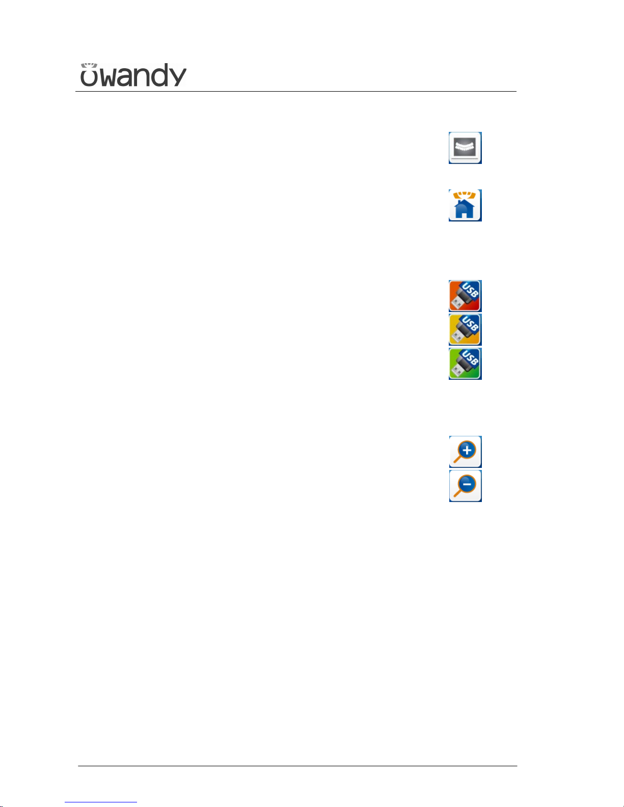
This key displays the acquired image
stored in the memory of the unit; the
main menu area is replaced by the
image.
View image
This key is used to return to the control
panel (main menu) when an acquired
image is displayed.
Return Main Menu
The Pen Drive key appears when a pen
drive (memory stick) is inserted in the
USB connector of the control panel; it
writes the acquired image that is stored
in the memory of the unit on the pen
drive that is inserted.
When this key is green, the pen drive is
recognised, has enough free space and
is ready for use.
When the key is orange, it is busy; the
image is being written on the pen drive.
When the key is red, the pen drive does
not have enough free space on it, or it
is not recognised.
Full/error
In operation
Ready for use
When the acquired image is displayed
on the control panel screen, it is
possible to zoom in and out of the
image using these two keys.
Zoom in
Zoom out
Page 38
USER'S MANUAL
General instructions for use
(Rev. 0) I-Max Touch (110-120V)
33
6.1.1 Key function description
Figure 7 - Control panel
LEGEND:
Messages
Display: indicates operative messages, warnings and
exposure parameters.
Signal lights
1 - Light indicating the machine is ready for X-ray
emission (green LED)
2 - Yellow LED indicating X-ray emission
Manual setting of exposure parameters
3 - kV, mA and Soft Tissue Filter increase keys
4 - kV, mA and Soft Tissue Filter decrease keys
Preparation functions
5 - Key to set Test function
6 - Key for:
> Resetting and realigning the device's axes (in
case of collision with patient or in case of
release of rays button)
> Repositioning the rotation group (to bring the
group to the initial position after the examination
and to exit from the "making an exposure")
mode
> Confirmation
Anatomic selection
7 - Patient selection key: Adult or Child
8 - Size selection key: Small, Normal, or Large
9 - Arch selection key: Protruded, Standard or
Retracted (for panoramic execution)
Examination mode
10 - Exam mode selection key
11 +12 - Type of exam selection keys (only for
panoramic mode)
13 - Mode indicator: Anatomic or Manual
Centring devices
14 - Sagittal and Frankfurt plane centring device
ON/OFF key
Column height adjustment
15 - Column up key
16 - Column down key
Other
17 - Display acquired image key
18 - USB Pen Drive key
1
2
6
10
18
17
7
8
14
3
4
9
Display11+12
13
5
16
15
Page 39
USER'S MANUAL
General instructions for use
I-Max Touch (110-120V) (Rev. 0)
34
Figure 8 – Acquired image display
LEGEND:
Messages
Display: indicates operative messages, warnings and
exposure parameters.
Other
18 - USB Pen Drive key
19 - Return to control panel (main menu)
USB port: to connect a pen drive
Acquired image display
Image: displays the last acquired image, stored in the
memory of the unit
20 - Zoom out on the image
21 - Zoom in on the image
21
Image
Display
20
18
19
USB port
Page 40
USER'S MANUAL
General instructions for use
(Rev. 0) I-Max Touch (110-120V)
35
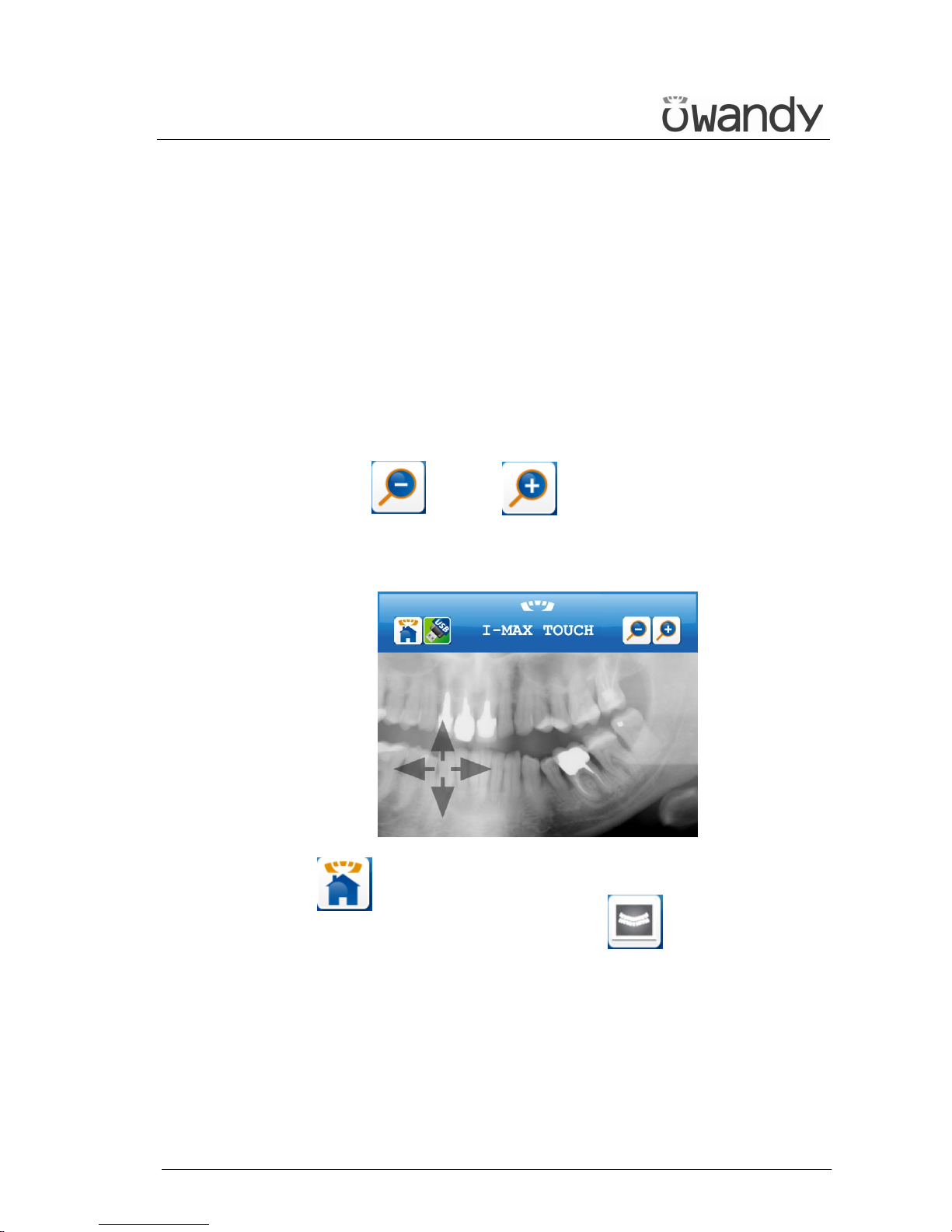
6.1.2 Acquired image display description
Once an image has been acquired it is transferred to the computer
through the network (if connected) and/or written on the USB pen drive
(if inserted); the image remains in the memory of the unit until the unit is
switched off or until a new image is acquired that replaces the previous
one.
During acquisition, image is progressively displayed on the screen,
adjusted to have the whole image in the screen. During this processing
step, zoom keys are not displayed.
As soon as the image is acquired and fully processed, it is displayed on
the screen of the control panel. The image can be zoomed in and out on,
using keys (20) and (21) .
When the image is zoomed in on, it is possible to move around the image
to display parts of the image that are not visible on the screen; this can
be done using a stylus or using a finger.
Key (19) returns to the control panel, allowing for the acquisition
of a new image. In the control panel, key (17) returns to the
display of the acquired image.
Page 41
USER'S MANUAL
General instructions for use
I-Max Touch (110-120V) (Rev. 0)
36
6.1.3 Pen Drive function description
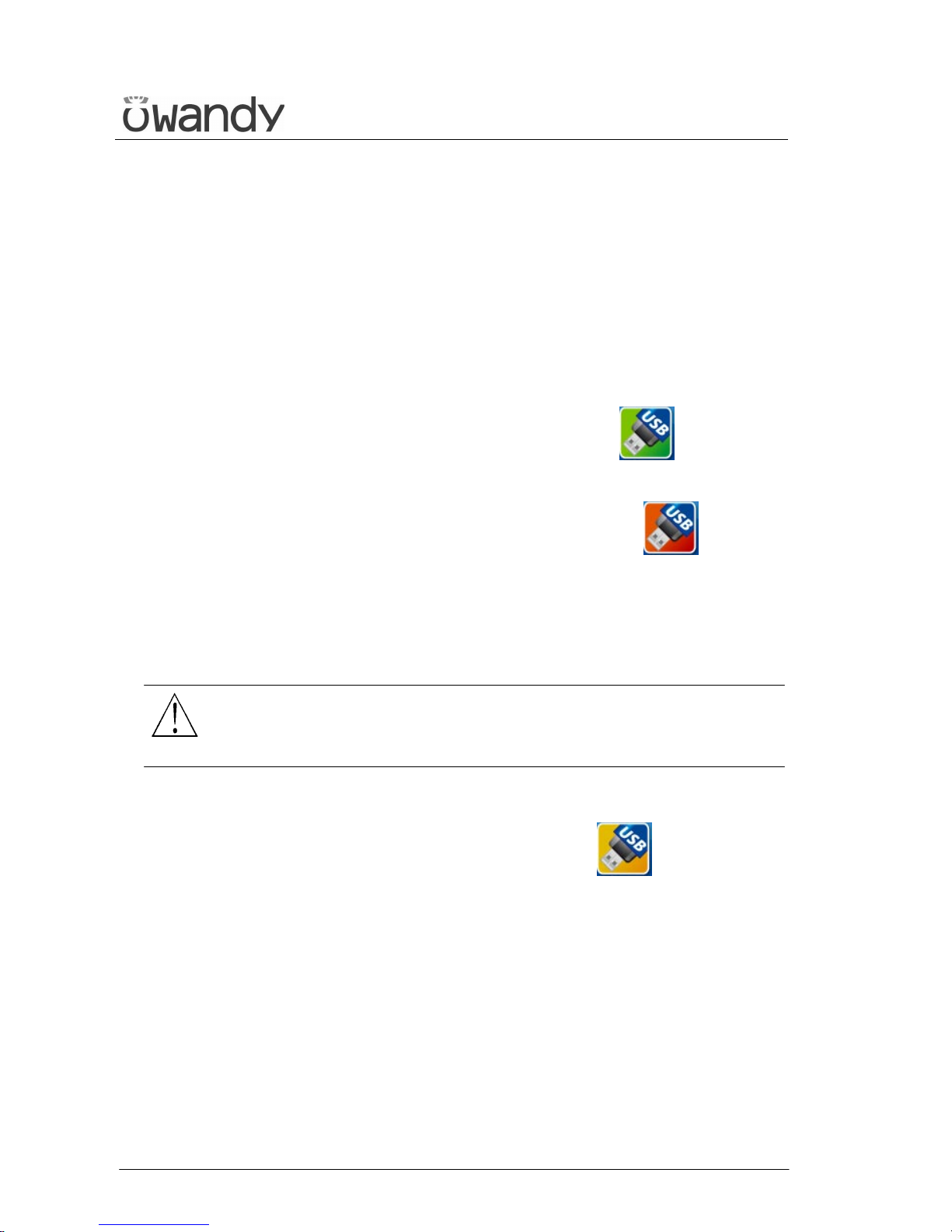
A pen drive can be inserted in the USB port at the top of the control
panel. The pen drive has to be formatted in FAT or FAT32 (not in NTFS;
please refer to your Windows manual and help for more information on
formatting).
As soon as the pen drive has been inserted, the unit will verify it.
• If the pen drive is formatted with the right file system and there is
enough free space available to save at least one image, the pen drive
key (18) on the screen will be displayed in green .
• If the pen drive is not formatted with the right file system or if there
is not enough free space available to save at least one image, the pen
drive key (18) on the screen will be displayed in red .
Please verify that there is enough free space on the pen drive, if not
please free up at least 25 MB of space. Please verify that the pen
drive has been formatted with the FAT or FAT32 and not with the
NTSF (or Linux or Mac) file system, if not please use another pen
drive or reformat the pen drive with the correct file system.
WARNING:
Make sure, before reformatting a pen drive, to copy all the data it
contains onto your harddisk or CD/DVD; once the pen drive is
reformatted all data on it will be irreparably lost!
• When an image is being written to the pen drive, the pen drive key
(18) on the screen will be displayed in orange (busy state).
Do not extract the Pen Drive from the keyboard when the Pen Drive
key (18) is orange.
• When the keyboard displays the acquired image, pressing the green
Pen Drive key (18) will save the current acquired image on Pen Drive.
Page 42

USER'S MANUAL
General instructions for use
(Rev. 0) I-Max Touch (110-120V)
37
6.2 Digital Sensor
The I-Max Touch is equipped with two types of digital sensors, depending
on the version:
• Sensor PAN: it is a sensor suitable for Panoramic-type imaging, i.e.
all images with a 14 cm-high field; all Panoramic, TMJ, and Sinus
images belong to this type. Depending on the version, this sensor can
be either movable from the sensor holder, or fixed (not removable) on
the same holder. In case the sensor is fixed to the sensor holder, the
latter cannot be rotated to make free the part where rays go through
for the execution of the cephalometric examination.
• PAN/CEPH sensor: it offers a wider use flexibility, as it can carry out
both Panoramic and Cephalometric-type images. This sensor can
always be removed from its sensor holder's.
The I-Max Touch can also be configured in the "double sensor" version,
where both PAN and PAN/CEPH sensors are present.
The I-Max Touch control system takes care of checking the consistency of
the safety measures that allow for the correct use of the digital sensor; in
particular:
• To prevent the acquisition in case the image management and
processing system is not ready to receive the image itself, by
displaying the message "Sensor not ready"
• To prevent the CEPH exposure in case the PAN sensor is in the CEPH
position, by displaying the message "Sensor not on Ceph"
• To prevent the exposure in case, when a double-sensor system is
present, the PAN sensor holder is not completely open, allowing the
clearing of the X-ray beam path. The message "Open cassette holder"
is displayed.
NOTE:
All sensor types are equipped with a shock detection sensor; this sensor
is also visible from the outside to enable to operator to perform checks.
Possible shocks are displayed by a change in colour (from
transparent/white to red) of this sensor. The digital sensor can still
function correctly also when the colour changes, displaying a fall that
might also not have damaged the sensor.
NOTE:
The fall sensor colour change interrupts the warranty on the sensor.
*
*
Page 43
USER'S MANUAL
General instructions for use
I-Max Touch (110-120V) (Rev. 0)
38
6.2.1 Inserting the sensor in the sensor holder
The digital sensor is equipped with a handgrip used to safely transport
the sensor from one holder to the other, in order to minimise the risk of
fall. The system used to hook the mobile sensor to the holder is also
engineered to reduce the sensor's risk of fall due to failure to hook the
sensor and/or due to early release.
Inside the transport handgrip there is a lever that controls the sensor's
hooking and release operations; at the same time, this lever works on the
electronic connector in order to guarantee the correctness of the
connection operations. On the fixed part of the sensor holder, there are
two hooks that need to be inserted into the corresponding gaps on the
mobile part of the sensor. On this latter, metallic plugs have been
mounted which, by joining in the corresponding fixed part, guide all
parts to a position suitable for the execution of a safe and stable contact.
In order to insert the sensor in the desired station, carry out the following
operations:
1. Grip the sensor by the appropriate handgrip; close your fingers to
form a fist, by engaging the control lever and bring it to the position
where the lever disappears inside the handgrip, so that the whole
mobile system retracts.
2. Keep the sensor with the relative handgrips vertical, so that the
upper plane is parallel to the horizontal part of the sensor holder,
bring the sensor close to the fixed station, by engaging the protruding
part of the mobile sensor into the relative casing.
3. Push the sensor mobile part to the very end, in order to engage the
mobile part onto the fixed hooking system.
4. Carry out a movement towards the lower part, ensuring that the
movement is complete.
5. Only at this point, release the hooking lever, checking that the
sensor is correctly engaged before releasing the handgrip.
WARNING:
During the lever releasing operation, hold the sensor firmly, to prevent
the sensor from falling during the insertion phase due to possible errors.
Page 44

USER'S MANUAL
General instructions for use
(Rev. 0) I-Max Touch (110-120V)
39
6.2.2 Release of the sensor from the sensor holder
The operations for releasing the sensor from the relative sensor holder
are specular to the ones described for the hooking of the same.
1. Grip the sensor by the appropriate handgrip; close the fingers to form
a fist, by engaging the control lever and bring it to the position where
the same disappears inside the handgrip, so that the whole mobile
system retracts and the electronic connectors and the reference plugs
are completely released.
2. Grip firmly the handgrip, and move towards the upper part of the
digital sensor, in order to free the mobile part from the hooking
system.
3. By keeping the sensor with the upper part parallel to the relative
horizontal part, carry out a horizontal movement in order to free the
protruding part of the sensor from the relative casing of the sensor
holder, disengaging thus the hooking system.
4. Always gripping firmly the sensor, in order to avoid accidental falls, it
is possible to freely move the sensor to the desired position.
Page 45
USER'S MANUAL
General instructions for use
I-Max Touch (110-120V) (Rev. 0)
40
6.3 Switching on the device
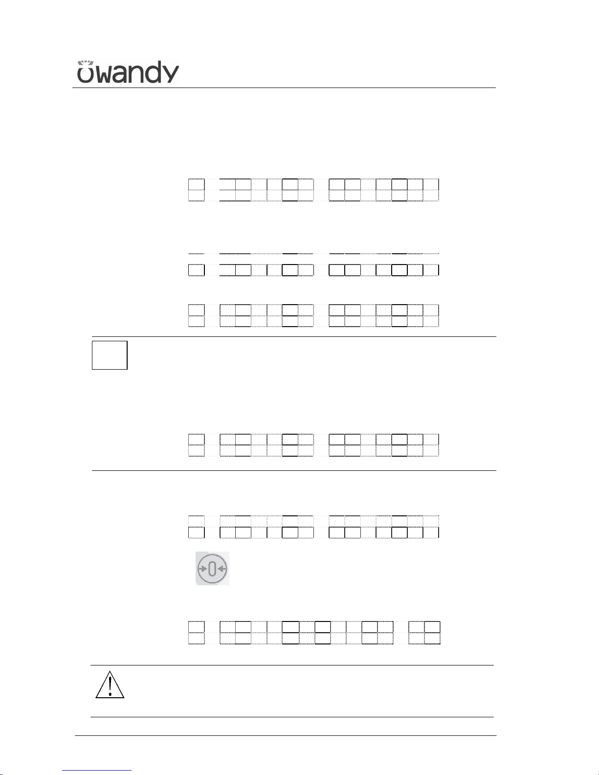
Press the green button on the base of the column to switch the system
on; the display shows:
I M A X T O U C H
H W = x . x x S W = x x . x x
This message will be present for about 20 seconds.
After this time the LEDs on the control panel start blinking and on the
display will be present the following message:
I M A X T O U C H
R E L E A S E * . * *
3 seconds later, the display shows the following message:
> T E S T <
NOTE:
During this phase, the I-Max Touch does not perform any movement, it
just performs a series of checks which, in the event of negative result,
could require the intervention of the technician.
The only problem that can be solved by the user is related to the position
of the PAN sensor holder; in this case, the following message will be
displayed:
C L O S E C A S S E T T E
P A N O R A M I C
When the self-diagnosis is completed, the following appears on the
display:
M A C H I N E S E T T I N G
P R E S S > 0 <
Press key (6) to start the device alignment phase.
Once the key has been pressed, the message disappears and the display
shows the following message during the alignment of the axes:
W A I T F O R . . .
M A C H I N E S E T T I N G
WARNING:
During this phase, the machine checks for possible obstacles that may
create collisions simulating the movements performed during the
examination.
*
Page 46
USER'S MANUAL
General instructions for use
(Rev. 0) I-Max Touch (110-120V)
41
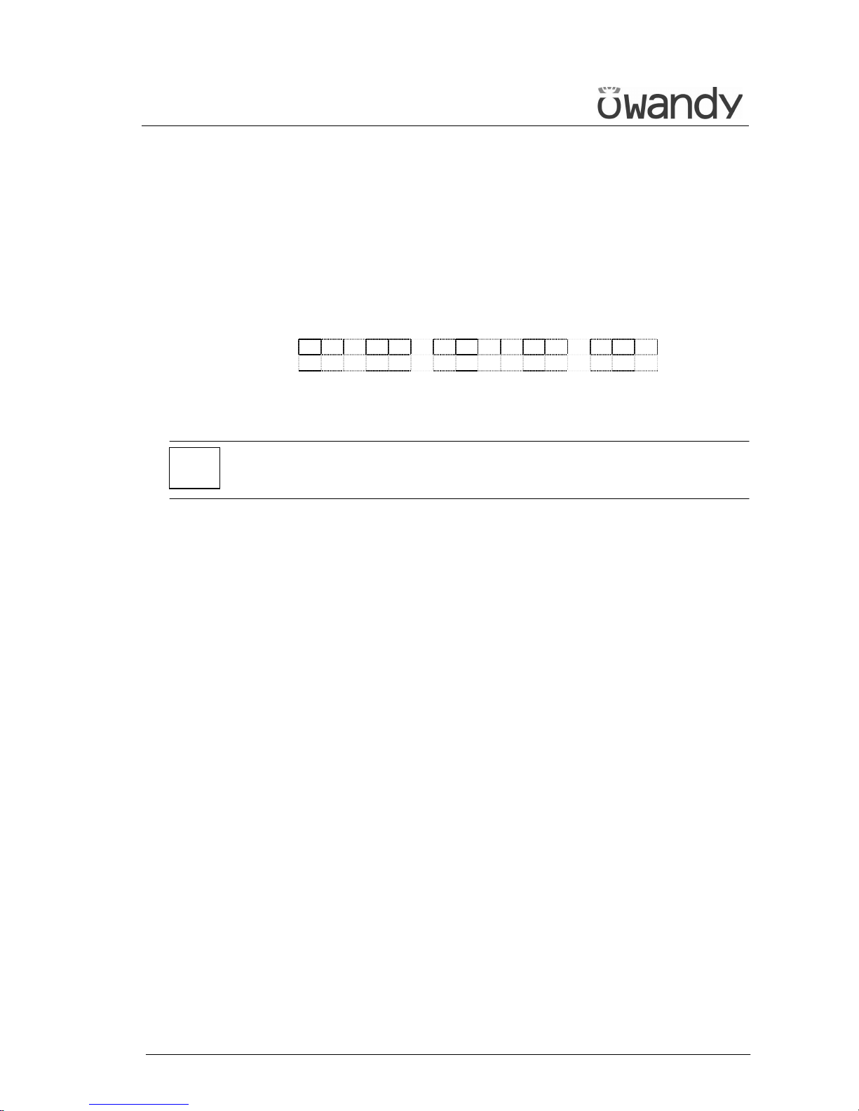
After 3 seconds, the following configuration will be automatically set by
the system:
• ADULT with the display of the corresponding graphic in the button
• MEDIUM SIZE with the display of the corresponding graphic in the
button
• STANDARD DENTITION with the display of the corresponding
graphic in the button
and the display shows (for instance):
x x k V x x m A 1 3 . 8 s
P A N O R A M I C - S T D
THE MACHINE IS READY
NOTE:
The above mentioned position is chosen also in the event that, for any
reason, the device repeats the initialisation phase.
*
Page 47
USER'S MANUAL
General instructions for use
I-Max Touch (110-120V) (Rev. 0)
42
6.4 Positioning of chin support
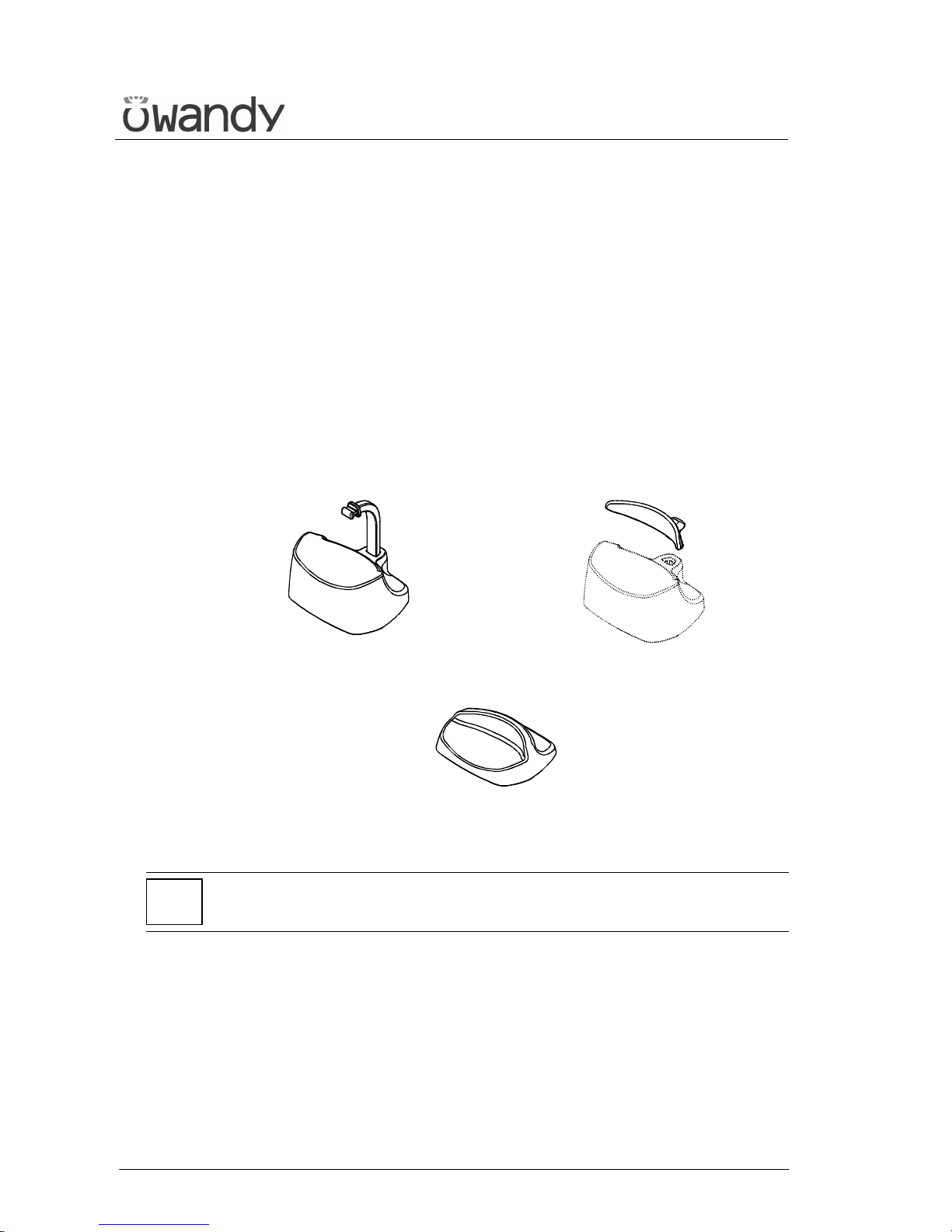
The I-Max Touch is equipped with two types of supports: a standard
support fitted with a special removable appendix for edentulous patients,
and a lower one, for SINUS/TMJ examinations.
The standard chin support must be used, in Panoramic mode, with all
the people who can assure a tight grip on the centring bite. The appendix
for edentulous patients must be applied only for patients who cannot
assure a tight grip on the bite or are not co-operating and might move
during the examination.
For the SINUS/TMJ examinations, there is special support that, being in
a lower position, ensures a better centring of the interested area in the
rays field.
Panoramic standard
chin support
Edentulous patients
appendix
SINUS/TMJ
chin support
NOTE:
Always remove the chin support when performing Ceph examinations.
*
Page 48

USER'S MANUAL
General instructions for use
(Rev. 0) I-Max Touch (110-120V)
43
6.5 Panoramic examination
When making a panoramic examination, the tube-head support arm
(X-rays generator) makes a continuously rotating movement.
After an initial acceleration, rotation is made at a constant speed. At the
same time the arm carries out a scanning towards the support column.
The X-rays are emitted only when the rotating arm is at constant rotation
speed.
The patient's centring is assisted by two linear luminous laser beams,
which indicate the position of the sagittal medial plane; the
corresponding patient's plane needs to be aligned with this plane. The
latter is held in place, during the examination phase, by means of temple
clasps rods and of a forehead support. A fourth fixing point is determined
by the chin support.
Page 49
USER'S MANUAL
General instructions for use
I-Max Touch (110-120V) (Rev. 0)
44
6.5.1 Preparation of the device
When the unit is switched on, the Panoramic Examination is selected as
standard. If the operator has previously made another kind of
examination to select Panoramic use the key "Examination Mode
Selection" (10) .
By doing so, it is possible to modify the type of examination between STD
PANORAMIC, TMJ O/C, SINUS, CEPH; such variation takes place with
continuous rotation, therefore, to move from the TMJ O/C mode to the
STD PANORAMIC the key needs to be pressed 3 times.
After selection Panoramic, the system positions itself with the following
configuration:
• ADULT with the display of the corresponding graphic in the button
• MEDIUM SIZE with the display of the corresponding graphic in the
button
• STANDARD DENTITION with the display of the corresponding
graphic in the button
and the display and graphic showing the default exposure parameters (if
this is the first panoramic exposure), or the exposure parameters (kV and
mA) of the last exposure performed. For example:
7 2 k V 0 6 m A 1 3 . 8 s
P A N O R A M I C - S T D
Once the settings have been completed, the chin support must be placed
in position.
The key "Examination Mode Selection" (10) enables the selection of
specific submodes, selectable by means of the keys "Arrow right" (12) and
"Arrow left" (11), enabling the sliding in one direction or another.
Previous examination Next examination
For the Panoramic examination, the following selections are possible:
STD Panoramic -> Right Emi-panoramic -> Left Emi-panoramic ->
Reduced dose Panoramic -> Improved orthogonality dentition -> Frontal
dentition -> STD Panoramic.
This selection is cyclic, so pressing the button repeatedly will change the
selected mode.
Page 50
USER'S MANUAL
General instructions for use
(Rev. 0) I-Max Touch (110-120V)
45
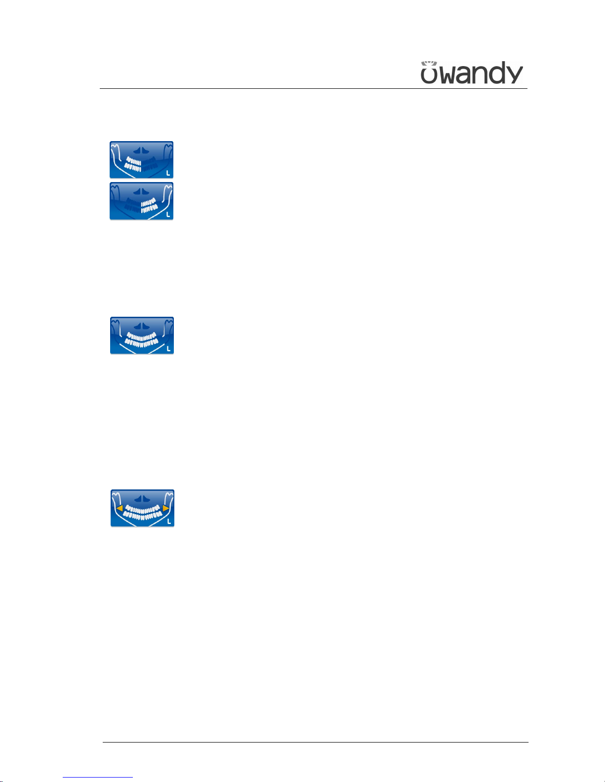
• Right / Left Emi-panoramic
The Emi-panoramic mode, right or left, means that only the
corresponding half arch is irradiated; the emission will start from the
beginning, to just after the mid sagittal plane for the right part. For
the left, it will start just before the mid sagittal plane and continue
until the end of the rotation.
These two kinds of examinations are usually used when it is already
known that the patient has a problem on only one half of the arch, so
it is possible to reduce the irradiation of the patient.
Follow the instructions for normal Panoramic for patient
positioning.
• Reduced dose Panoramic
The reduced dose Panoramic examination makes an X-ray only of the
dental arch, excluding from the image the ascending rami of the
temporo-mandibular joint; the examination is performed with the
same trajectory of the standard Panoramic, by reducing the rays
emission time.
This examination is used, for instance, during the treatment
continuation phases or where the lack of pathologies of the same
joint is already known.
Follow the instructions for normal Panoramic for patient
positioning.
• Improved orthogonality dentition
The improved orthogonality Panoramic delivers the image of the pure
dental arch cutting out from the image the ascending rami branches
of the temporo mandibular joint; the trajectory of the rotating arms
is, however, optimised for a better orthogonality between the X-ray
beam and the incident sections of near teeth.
Thus the image has reduced overlapping of the teeth, improving the
diagnosis of interproximal decay.
As a consequence of the different trajectory, the focus layer, mainly
in the front teeth area, is smaller and the patient positioning for this
examination needs more care.
Follow the instructions for normal Panoramic for patient
positioning.
Page 51
USER'S MANUAL
General instructions for use
I-Max Touch (110-120V) (Rev. 0)
46
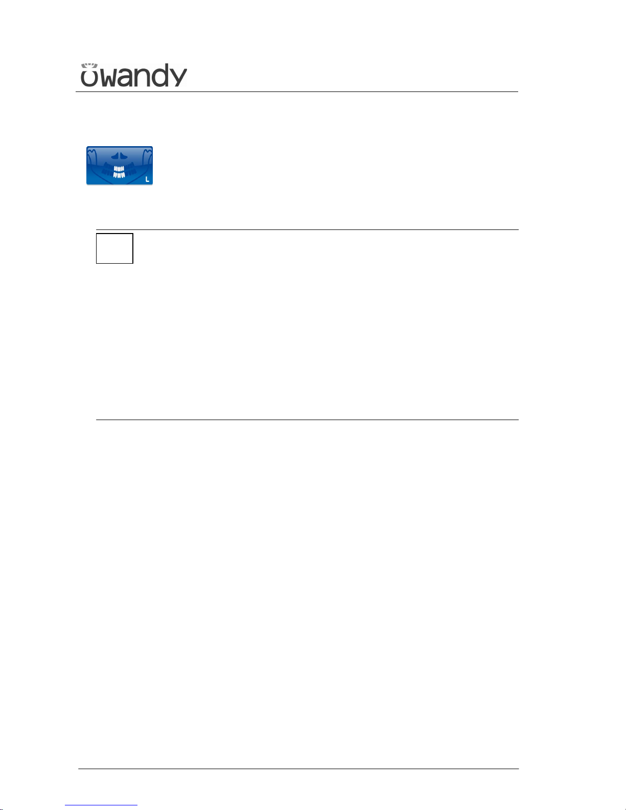
• Frontal dentition
The Frontal dentition examination performs an X-ray of the dentition
frontal area (roughly from canine to canine).
Follow the instructions for normal Panoramic for patient
positioning.
NOTE:
The I-Max Touch is based on a standard dentition and ascending rami
shape.
This shape, based on statistic study, establishes a form for the
dentomaxillofacial complex that it is assumed as "standard".
The I-Max Touch follows a rototranslation path which maintains constant
the magnification factor stated in the technical characteristics of each
type of exam along this "standard" shape and in the dentition area. The
patient’s anatomy can differ significantly from the statistical model, so
the magnification factor is not maintained and can be different from the
value stated. Based on his experience and competence, the user has to
judge this variation.
IN ANY CASE, THE RADIOGRAPHY IMAGES CANNOT BE USED TO
PERFORM CALCULATIONS OF DISTANCES, ANGLES ETC.
*
Page 52
USER'S MANUAL
General instructions for use
(Rev. 0) I-Max Touch (110-120V)
47
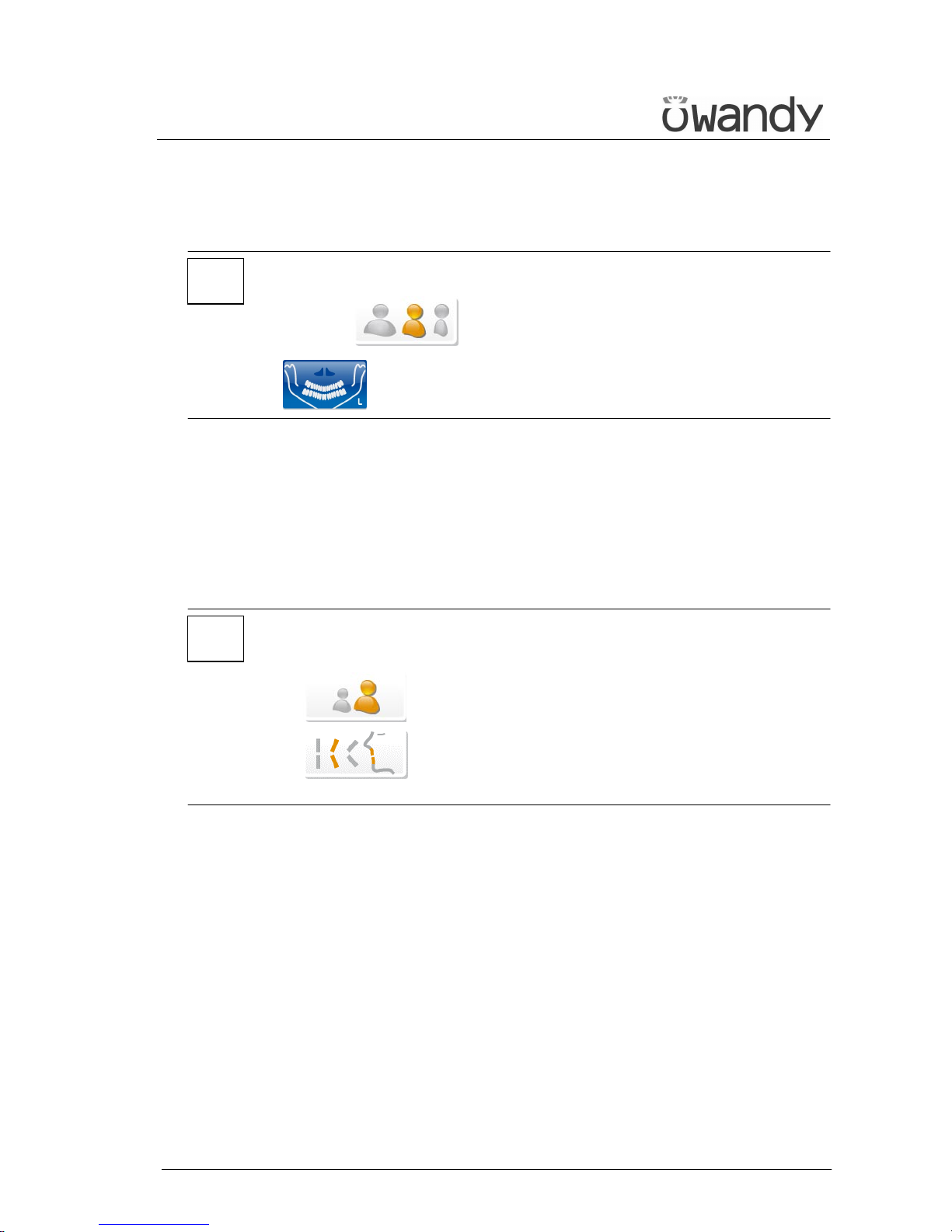
6.5.2 Anatomic / manual exposure
NOTE:
If the previous exam was carried out manually, just press the key "Size
Selection" (8) or the key "Selection Examination Mode"
(10) .
After setting the machine, it is possible to choose between the following
two operating modes:
• ANATOMIC: with the values of kV and mA programmed on the basis
of the type of patient and the size.
• MANUAL: with the possibility to vary the kV and mA values already
set.
NOTE:
In manual condition, the "Anatomic/Manual mode" (13) indicator
displays "M" to indicate the manual mode; it is possible to press
key (7) to change from Adult to Child and press
key (9) to modify the type of biting from Normal to
Protruded to Retracted.
*
*
Page 53
USER'S MANUAL
General instructions for use
I-Max Touch (110-120V) (Rev. 0)
48
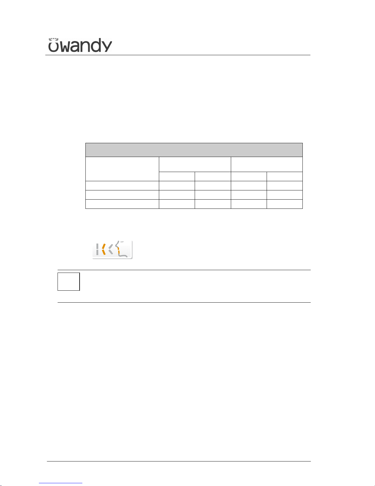
6.5.2.1 Anatomic exposure
Select the type of patient with the Adult/Child key (7).
Select the type of build with the Size (8) key (small - medium - large).
On the basis of these selections, the display will visualise the kV and mA
settings as in the table.
Exposure values in PAN mode
Adult Patient
(13.8 seconds)
Child Patient
(13.4 seconds)
kV mA kV mA
Small 68 6 64 6
Medium 72 6 66 6
Large 74 6 68 6
Table 2
Select the type of biting with the key "Type of Biting Selection"
(9) .
NOTE:
The type of biting does not affect the kV and mA values, but it affects the
position of the focus layer, by adapting the rotation movement to the
patient's anatomy.
*
Page 54
USER'S MANUAL
General instructions for use
(Rev. 0) I-Max Touch (110-120V)
49
6.5.2.2 Manual exposure
If the kV and mA combinations of the Table 2 are not considered suitable
for a specific examination, it will be possible to set new parameters using
the manual mode.
To modify the kV or mA values, press any of the up (3) or down
(4) arrows of the KV or mA parameters, the blue frames around the
"Examination mode selection", the "Adult/Child Selection" (7) and the
"Size Selection" (8) keys will disappear, orange frames will appear around
the up and down arrow keys of the parameters (3) and (4) and the
"Anatomic/Manual mode" indicator will display "M". The display will
show respectively one of the following two indications:
> x x k V x x m A x x . x s
P A N O R A M I C - S T D
or
x x k V > x x m A x x . x s
P A N O R A M I C - S T D
The symbol ">" indicates which parameter is being changed.
A parameter can be modified by pressing the increase key (3)
and the decrease key (4) of that parameter repeatedly.
The kV value can vary between 60 and 86 kV, with 2 kV steps.
The value of mA can vary between 6 and 10 mA, with 1 mA steps.
NOTE:
To change the values rapidly, keep the increase key (3) or decrease key
(4) pressed.
Select the type of mouth with the key "Type of Biting Selection"
(9) .
*
Page 55
USER'S MANUAL
General instructions for use
I-Max Touch (110-120V) (Rev. 0)
50
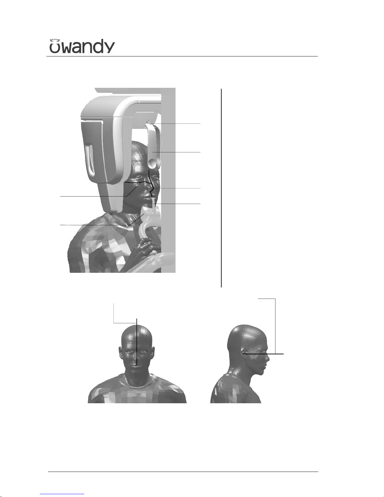
Panoramic positioning
1
2
3
4
45
46
Figure 9
Legend positioning devices and
patient centring
1 Panoramic chin rest
2 Centring bite
3 Temple clasps - Forehead
support
4 Temple clasps - Forehead
support release knobs
45 46
Figure 10
Legend of Reference Lines
45 Sagittal medial line
46 Frankfurt plane line
Page 56
USER'S MANUAL
General instructions for use
(Rev. 0) I-Max Touch (110-120V)
51
6.5.3 Preparation of the patient
1. Ask the patient to remove all metallic objects located in the area to be
X-rayed (necklaces, earrings, glasses, hairpins, removable dental
prosthesis, etc.). Ensure that there are no thick garments in the area
to be X-rayed (coats, jackets, ties, etc.).
2. Ask the patient to put on the protective apron, or something similar,
making sure that it does not interfere with the trajectory of the X-ray
beams.
3. Place the patient in a standing position at the chin support.
With the keys "Column movement" (15/16) lift/lower the
column until the chin support is aligned with the patient's chin.
4. Position the patient with the temple clasps (Figure 9) ensuring that
the chin rests on the special support; the hands should rest on the
front handles. Ask the patient to bite the reference notch of the bite
with his incisors (Figure 9). In case of edentulous patients, he/she
must rest the chin against the reference shoulder of the edentulous
chin support.
5. Instruct the patient to close his eyes.
6. Press the key "Centring devices ON" (14) .
Two laser beams will light up the sagittal medial plane line and the
horizontal line for the Frankfurt plane reference (the plane that
identifies a line that ideally links the ear hole - the auditory meatus with the lower part of the orbital fossa in Figure 10). Position the
patient's head in such a way as to ensure that the luminous beams
fall in correspondence with the respective anatomical references.
The luminous beam of the Frankfurt plane can be adjusted according
to the patient's height; this can be adjusted by means of the laser
knob on the side of the mirror.
NOTE:
The laser centring device will stay lit up until the "Centring devices ON"
(14) key or, at the end of the alignment, the key "Patient
Entrance" (6) is pressed to start the exposure preparation phase.
*
Page 57

USER'S MANUAL
General instructions for use
I-Max Touch (110-120V) (Rev. 0)
52
7. At this point, the patient must move his feet towards the column,
making sure to keep his head within the pre-aligned anatomical
references. In this way, you will have a greater extension of the spine
in the cervical area, improving the darkening of the X-ray in the
apical area of the incisors, and avoiding the collision of the tube-head
with the patient's shoulders. Check that the Frankfurt plane is still
horizontal.
8. Close the temple clasps (Figure 9) to help the patient keep a correct
position; bring also the forehead support close to the patient's
forehead and ensure that, in this phase, the patient has not changed
position.
9. Press the key "Patient Entrance" (6) to confirm the
parameters. The luminous centring devices switch off and the
rotating arm goes to its examination start position.
Once alignment has been completed, the following message will be
displayed:
x x k V x x m A x x . x s
S T A R T E X A M
x = value defined by the settings
The green LED "Ready for X-ray" lights up to indicate that pressing
the X-ray button once more will start the radiation phase.
10. Ask the patient to: keep the lips closed, bring the tongue
towards the palate, keep perfectly still and do not look at the
rotating arm during the movements.
Page 58
USER'S MANUAL
General instructions for use
(Rev. 0) I-Max Touch (110-120V)
53
6.5.4 Making an exposure
NOTE:
When the key "Test" (5) is pressed the Test function is
activated.
In this condition, it will be possible to make the unit perform all the
movements made during the examination without emitting X-rays.
Once the cycle is completed, deactivate the "Test" function by pressing
the key again.
WARNING:
During the emission of X-rays, the protection procedures for the operator
and personnel in the area must be in compliance with the local
regulations.
In all cases, it is recommended that during the emission of X-rays, only
the patient and operator be present in the room. If the operator is not
protected by suitable screens, he must stand at least 1.5 m (4.9 ft) away
from the emission of the rays (see the Figure 1 and Figure 2).
1. Verify once again that the exposure data are correct. If not, correct
them as described in paragraph 6.5.2.2; ensure that the machine's
indicator light "Ready for X-rays" will come on, so press the X-ray
button for the entire duration of the exposure, checking the
simultaneous working of the X-ray indicator light "X-rays emission"
(if you are within sight of the machine) and the acoustic ray signal.
The following message will be displayed first:
S T A R T E X A M
P R E - H E A T I N G . . .
and then (after 2 seconds), the following message will be displayed:
x x k V x x m A x x . x s
> X - R A Y <
x = value defined by the settings
NOTE:
If the machine is in the "Test" mode, the display will show:
T E S T
X R A Y N O T A C T I V E
*
*
Page 59
USER'S MANUAL
General instructions for use
I-Max Touch (110-120V) (Rev. 0)
54
NOTE:
The I-Max Touch assumes that the digital sensor is ready: if this is not
the case, the following error message will be displayed:
D I G I T A L S E N S O R
I S N O T R E A D Y
Refer to the Manual of the Digital Acquisition System to correct the
situation.
To reset the message on the I-Max Touch, press key .
NOTE:
The rotation of the arm and the emission of the X-rays will start with a
delay of 2 seconds from when the X-ray button is pressed. Since the
X-ray button is a "dead man’s switch", it must be kept pressed until
the end of the exposure.
2. Once the exposure is completed, the system will rotate back. When it
has completed this movement, the display shows the message:
P A T I E N T E X I T
P R E S S > 0 <
and it will be necessary to free the patient from the positioning
device.
NOTE:
If the examination is made in "Test" mode with the patient already in
position, he must not be removed from the temple clasp group, to avoid
having to reposition him. Press the "Patient Entrance" (6) key to
return the unit to its initial position. This movement can be stopped by
pressing the same key.
Now the system is ready to perform a new examination.
3. Press the key "Patient Entrance" (6) , the unit will move back
to the starting position showing the message:
P L E A S E W A I T . . .
The Digital Acquisition System will, in the meantime, process the
image and display it.
*
*
*
Page 60
USER'S MANUAL
General instructions for use
(Rev. 0) I-Max Touch (110-120V)
55
NOTE:
If you try to perform a new exam before the cooling period has elapsed
(4 minutes), the following message will be displayed indicating the time to
wait before performing a new examination:
T U B E C O O L I N G
P L E A S E W A I T x x x s
The waiting time allows the anode in the radiogenic tube to cool down.
WARNING:
After every examination, clean the chin support, the handles and
the temple clasps group thoroughly and change the disposable bite
protective sleeve.
NOTE:
If, during the exposure, the patient moves, or the machine collides with
the patient himself (or with any object), or you realise that the
parameters set are not correct, you must release the X-ray button
immediately, interrupting the emission of X-rays and the movement of
the arm.
If this occurs, the following message will be displayed:
E 2 0 6
P R E S S > 0 <
All the motors will switch off, and it will be possible, if necessary, to
manually rotate the arm, allowing the patient to come out; it is
recommended that this movement has to be made with great care in
order to prevent damage to the machine.
Then press the "Patient Entrance" (6) key and the display will
show:
M A C H I N E S E T T I N G
P R E S S > 0 <
and then:
WA I T F O R
M A C H I N E S E T T I N G
The system now returns to its initial position and the patient must be
repositioned.
*
*
Page 61
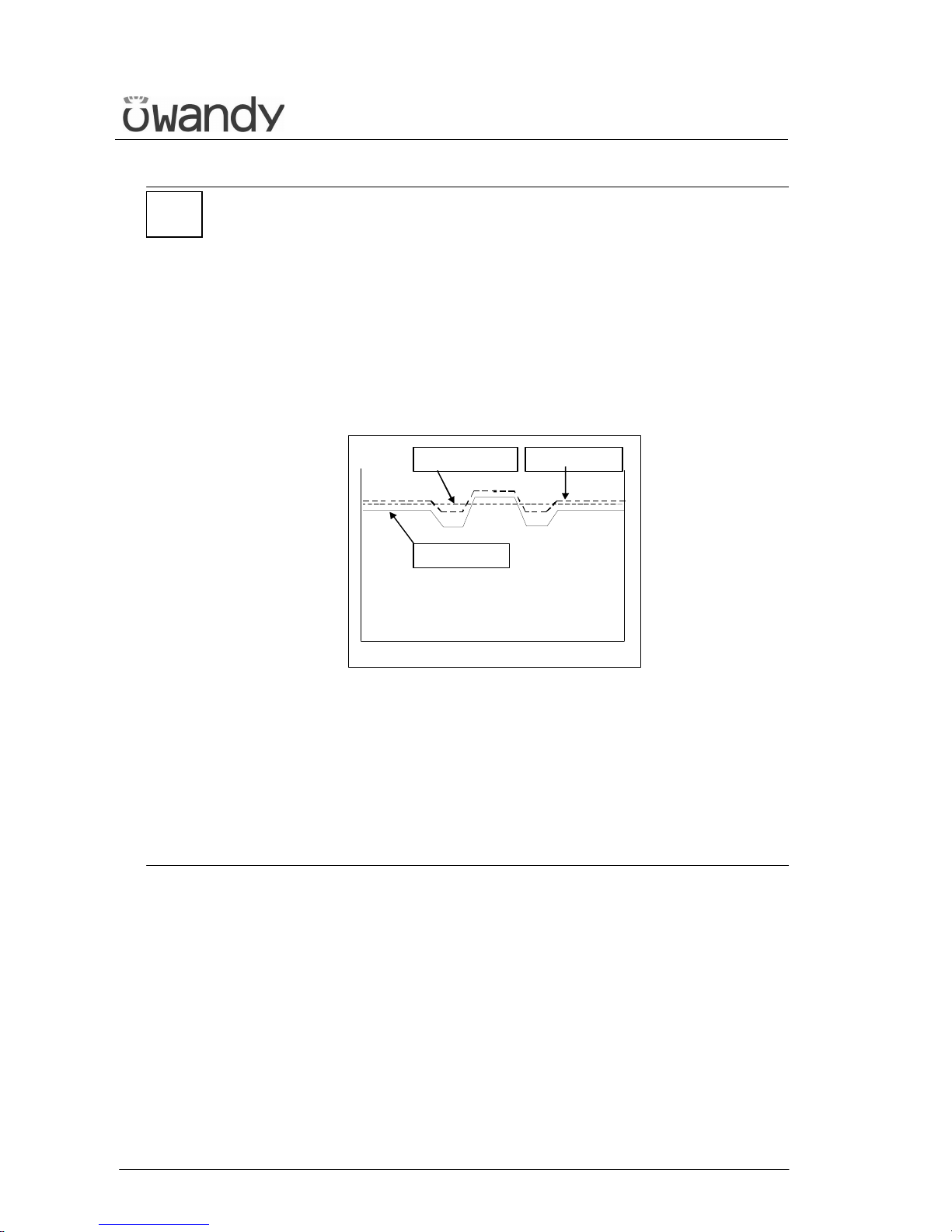
USER'S MANUAL
General instructions for use
I-Max Touch (110-120V) (Rev. 0)
56
NOTE:
During the Panoramic, the value of the exposure parameters varies
according to a fixed curve, to compensate the variations in absorption by
the patient's tissues. In this way, it is possible to obtain a good
uniformity of the image contrast. In particular, the chosen value of the
kV is lowered in the initial and end sections of the panoramic and
increased on the incisors/canine zone.
The tube current varies according to the kV, also if the set value is
slightly increased on the initial/end sections. These variations have the
effect of compensating the higher absorption of X-ray in the zone of the
spinal column. As an example, the variation of the parameters follows the
curve below:
Set value
Actual value mA
Actual valu e kV
The values displayed during the panoramic examination correspond to
the ones chosen by the user, while the real value in the various positions
of the examination cycle can be different; in any case, the system
guarantees that the accuracy of the exposure parameters is always
within the limits set by the international standards for the safety of
medical devices, IEC 60601-1. In particular, in accordance with
IEC 60601-2-7, the maximum deviation (including the correction
according to the above curve and instrumental doubt) is within ±10% for
the kV, while for the tube current it is within ± 15%.
*
Page 62
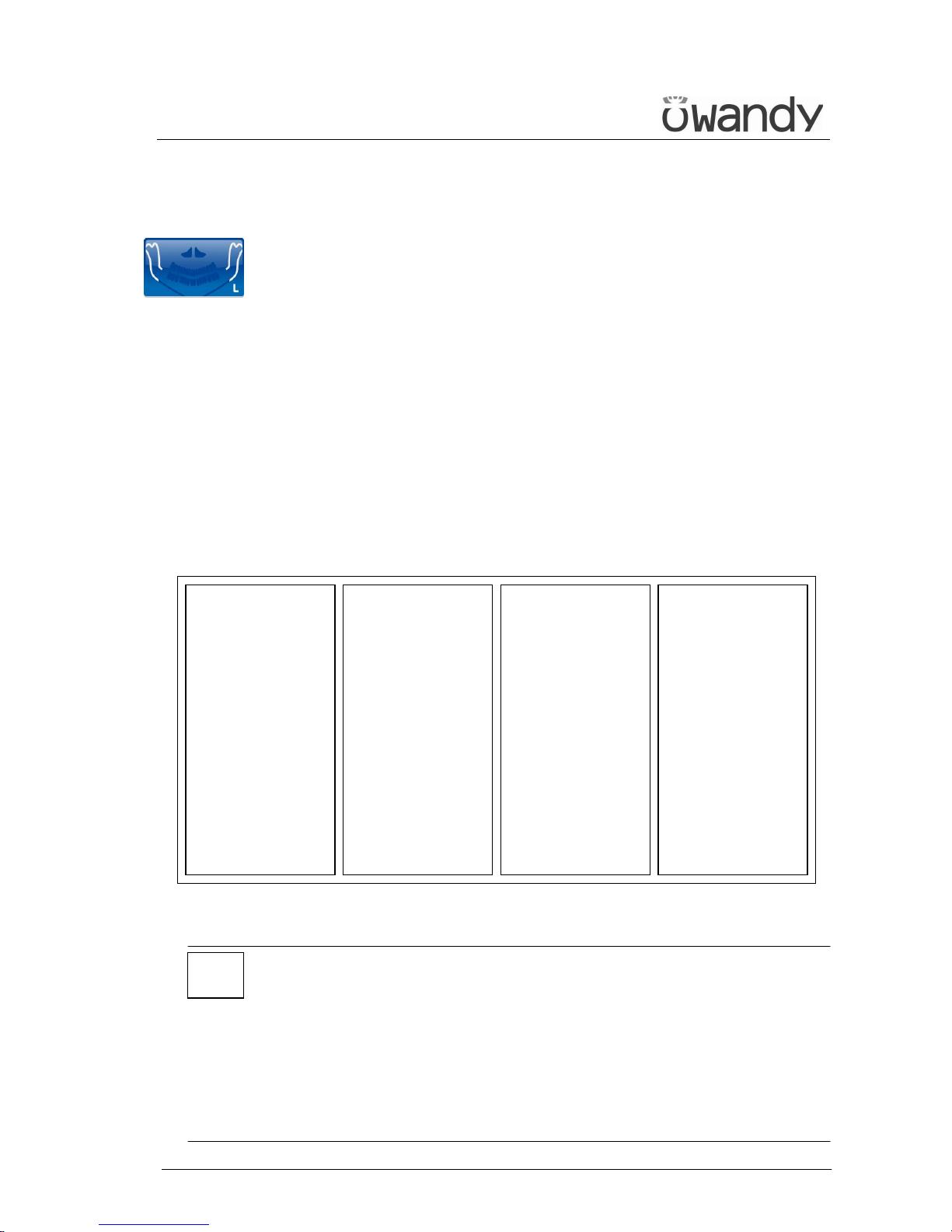
USER'S MANUAL
General instructions for use
(Rev. 0) I-Max Touch (110-120V)
57
6.6 TMJ examination
The TMJ examination with open/closed mouth is similar to panoramic;
the only difference is that the exposure is performed only on the involved
area (the temporo mandibular joint), then it stops, and starts again on
the second joint. The operation sequence of the examination is therefore
identical to the one described for the panoramic.
The temporo-mandibular joint examination makes use of a projection
geometry giving an image of the X-rayed condyle along a direction almost
parallel with its major axis, in order to achieve a clear view of its
positioning inside the cavity.
This TMJ function enables to obtain 4 different acquisitions on the same
image, by performing two rotational movements. The 4 images represent
the right and left condyle of the temporo-mandibular arch (TMJ) with
closed mouth and open mouth.
The position of the images couples the images corresponding to the same
condyle to help a diagnosis. Figure 11 shows the information related to
the single sectors.
RIGHT condyle with
closed mouth
1
st
exposure
RIGHT condyle with
open mouth
3
rd
exposure
LEFT condyle with
open mouth
4
th
exposure
LEFT condyle with
closed mouth
2
nd
exposure
Figure 11
NOTE:
During the TMJ examination, the emission of X-rays is intermittent (it is
interrupted during the transition phases between the various exposures),
but it is necessary to keep the X-ray button pressed for the whole
rotation time.
Do not release the X-ray button during the emission interruption if not
necessary.
The cooling phase of the tube-head occurs at the end of all 4 exposures.
In the CHILD position, exposure start is delayed by a few degrees with
respect to the ADULT position.
L
R
*
Page 63
USER'S MANUAL
General instructions for use
I-Max Touch (110-120V) (Rev. 0)
58
6.6.1 Preparation of the device
To select the TMJ examination, press key "Examination Mode Selection"
(10) until the following message and graphic is displayed:
x x k V x x m A 9 . 7 0 s
T M J O / C - > C L O S E
The system is positioned in the following configuration:
• ADULT with the display of the corresponding graphic in the button
• MEDIUM SIZE with the display of the corresponding graphic in the
button
and the display showing the default exposure parameters (if this is the
first TMJ exposure), or the exposure parameters (kV and mA) of the last
exposure performed. For example:
7 2 k V 0 6 m A 9 . 7 0 s
T M J O / C - > C L O S E
Once the settings have been completed, the chin support must be placed
in position if it has been removed (see paragraph 6.4).
NOTE:
The I-Max Touch is based on a standard dentition and ascending rami
shape.
This shape, based on statistical data, establishes a standard shape for
the dentomaxillofacial complex, defining also the position and the
direction of the condyles. The patient anatomy can differ significantly
from the statistical model; based on his experience and competence, the
user has to judge this variation.
IN ANY CASE, THE RADIOGRAPHY IMAGES CANNOT BE USED TO
PERFORM CALCULATIONS OF DISTANCES, ANGLES ETC.
*
Page 64
USER'S MANUAL
General instructions for use
(Rev. 0) I-Max Touch (110-120V)
59
6.6.2 Anatomic / Manual Exposure
NOTE:
If the previous exam was carried out manually, just press the key "Size
Selection" (8) or the key "Examination Mode Selection"
(10) .
After setting the machine, it is possible to choose between the following
two operating modes:
• ANATOMIC: with the values of kV and mA programmed on the basis
of the type of patient and the size.
• MANUAL: with the possibility to vary the kV and mA values already
set.
NOTE:
In the manual mode, the "Anatomic/Manual mode" (13) indicator
displays "M" to indicate the manual mode; it is possible to use
key (7) to change from Adult to Child.
*
*
Page 65
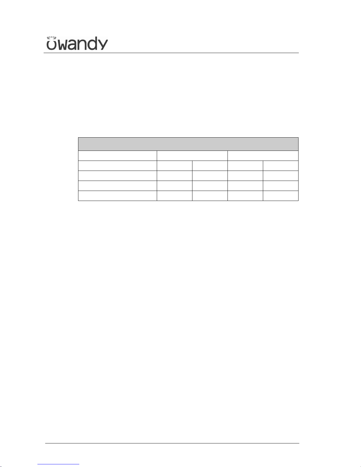
USER'S MANUAL
General instructions for use
I-Max Touch (110-120V) (Rev. 0)
60
6.6.2.1 Anatomic exposure
Select the type of patient with the Adult/Child key (7).
Select the type of build with the Size (8) key (small - medium - large).
On the basis of the selections made, the display will visualise the kV and
mA settings as in the table.
Exposure values in TMJ examination (9.7 sec)
Examination
Adult Child
TMJ mouth closed/open
kV mA kV mA
Small 68 6 62 6
Medium 72 6 64 6
Large 76 6 66 6
Table 3
The time (9.7 sec.) refers to the sum of the four exposures (2 closed
mouth exposures and 2 open mouth exposures).
Page 66
USER'S MANUAL
General instructions for use
(Rev. 0) I-Max Touch (110-120V)
61
6.6.2.2 Manual exposure
If the kV and mA combinations of the Table 3 are not considered suitable
for a specific examination, it will be possible to set new parameters using
the manual mode.
To modify the kV or mA values, press any of the up (3) or down
(4) arrows of the KV or mA parameters, the blue frames around the
"Examination mode selection", the "Adult/Child Selection" (7) and the
"Size Selection" (8) keys will disappear, orange frames will appear around
the up and down arrow keys of the parameters (3) and (4) and the
"Anatomic/Manual mode" indicator will display "M". The display will
show respectively one of the following two indications:
> x x k V x x m A 9 . 7 0 s
T M J O / C - > C L O S E
or
x x k V > x x m A 9 . 7 0 s
T M J O / C - > C L O S E
The symbol ">" indicates which parameter is being changed.
A parameter can be modified by pressing the increase key (3)
and the decrease key (4) of that parameter repeatedly.
The kV value can vary between 60 and 86 kV, with 2 kV steps.
The value of mA can vary between 6 and 10 mA, with 1 mA steps.
NOTE:
To change the values rapidly, keep the increase key (3) or decrease key
(4) pressed.
*
Page 67
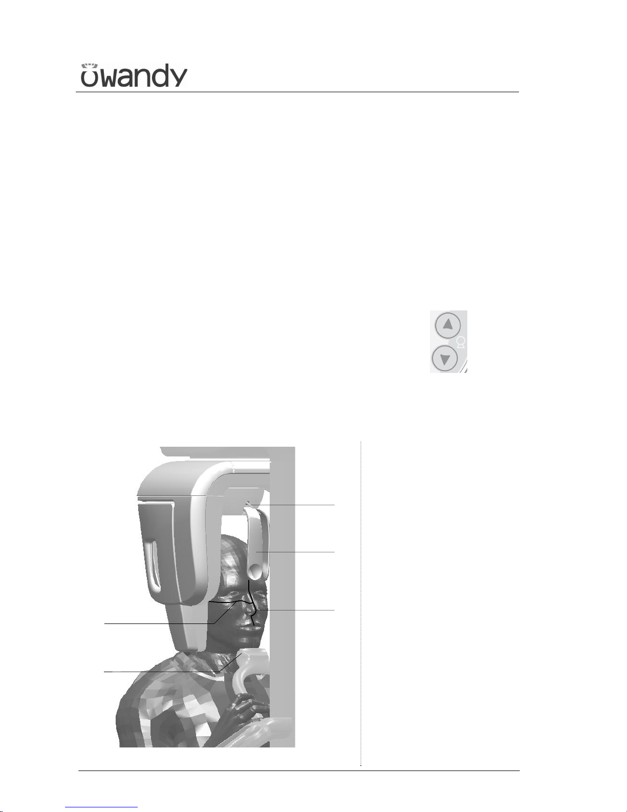
USER'S MANUAL
General instructions for use
I-Max Touch (110-120V) (Rev. 0)
62
6.6.3 TMJ closed mouth
6.6.3.1 Preparation of the patient
1. Ask the patient to remove all metallic objects located in the area to be
X-rayed (necklaces, earrings, glasses, hairpins, removable dental
prosthesis, etc.). Ensure that there are no thick garments in the area
to be X-rayed (coats, jackets, ties, etc.).
2. Ask the patient to put on the protective apron, or something similar,
making sure that it does not interfere with the trajectory of the X-ray
beams.
3. Place the patient in a standing position at the SINUS/TMJ chin
support. With the keys "Column movement" (15/16)
lift/lower the column until the chin support plane is aligned with the
patient's chin.
4. Position the patient with the temple clasps (Figure 12) asking him to
place his hands on the front support.
1
3
4
45
46
Figure 12 - TMJ closed mouth positioning
Legend of Reference Lines
45 Sagittal medial line
46 Frankfurt plane line
Legend positioning devices and
patient centring
1 SINUS/TMJ support
3 Temple clasps - Forehead
support
4 Temple clasps - Forehead
support release knobs
Page 68
USER'S MANUAL
General instructions for use
(Rev. 0) I-Max Touch (110-120V)
63
5. Instruct the patient to close his eyes.
6. Press the key "Centring devices ON" (14) .
Two laser beams will light up the sagittal medial plane line and the
horizontal line for the Frankfurt plane reference (the plane that
identifies a line that ideally links the ear hole - the auditory meatus with the lower part of the orbital fossa in Figure 10). Position the
patient's head in such a way as to ensure that the luminous beams
fall in correspondence with the respective anatomical references.
The luminous beam of the Frankfurt plane can be adjusted according
to the patient's height; this can be adjusted by means of the laser
knob on the side of the mirror.
NOTE:
The laser centring device will stay lit up until the "Centring Devices ON"
(14) key or, at the end of the alignment, the key "Patient Entrance"
(6) is pressed to start the exposure.
7. Close the temple clasps and bring the forehead support close; this
will help the patient to stay in a correct position. Check that, during
this phase, the patient has not changed position.
8. Press the key "Patient Entrance" (6) to confirm the
parameters. The luminous centring devices switch off and the
rotating arm goes to its examination start position. Once alignment
has been completed, the following message will be displayed:
x x k V x x m A 9 . 7 0 s
S T A R T E X A M
x = value defined by the settings
The green LED "Ready for X-ray" lights up to indicate that pressing
the X-ray button once more will start the radiation phase.
9. Ask the patient to: keep the lips closed, keep perfectly still and
do not look at the rotating arm during the movements.
*
Page 69
USER'S MANUAL
General instructions for use
I-Max Touch (110-120V) (Rev. 0)
64
6.6.3.2 Carrying out the first exposure (mouth closed)
WARNING:
During the emission of X-rays, the protection procedures for the operator
and personnel in the area must be in compliance with the local
regulations.
In all cases, it is recommended that during the emission of X-rays, only
the patient and operator be present in the room. If the operator is not
protected by suitable screens, he must stand at least 1.5 m (4.9 ft) away
from the emission of the rays (see the Figure 1 and Figure 2).
NOTE:
If deemed necessary, it is possible to check the interference of the
rotation movement with the shoulder of the patient; it is possible,
by pressing the key "Test" (5) , to activate the Test function.
In this condition, it will be possible to make the machine perform all the
movements made during the examination, but without emitting rays.
The test function of the TMJ closed/open mouth is the same as for the
panoramic mode and so there will not be a second rotation corresponding
to the open mouth exam. Once the cycle is completed, deactivate the
"Test" function by pressing the key again.
1. Check once again that the exposure data are correct. If not, correct
them as described in paragraph 6.6.2.2. ensure that the machine's
indicator light "Ready for X-ray" will come on, so press the X-ray
button for the entire duration of the exposure, checking the
simultaneous working of the ray indicator light "X-ray emission" (if
you are within sight of the machine) and the acoustic ray signal. The
following message will be displayed first:
S T A R T E X A M
P R E - H E A T I N G . . .
and then (after 2 seconds), the following message will be displayed:
x x k V x x m A 9 . 7 0 s
> X - R A Y <
x = value defined by the settings
NOTE:
If the machine is in the "Test" mode, the display will show:
T E S T
X R A Y N O T A C T I V E
*
*
Page 70
USER'S MANUAL
General instructions for use
(Rev. 0) I-Max Touch (110-120V)
65
NOTE:
The I-Max Touch assumes that the digital sensor is ready: if this is not
the case, the following error message will be displayed:
D I G I T A L S E N S O R
I S N O T R E A D Y
Refer to the Manual of the Digital Acquisition System to correct the
situation.
To reset the message on the I-Max Touch, press key .
NOTE:
The rotation of the arm and the emission of the X-rays will start with a
delay of 2 seconds from pressing the X-ray button. As the X-ray button
is a "dead man's switch", it is necessary to keep it pressed until the
end of the exposure.
The X-ray emission to the central part of the dental arch is suspended
during the examination phase, so the relative signals (sound and visual)
are therefore also suspended.
2. Once the exposure is completed, the system will carry out a short
return rotation and the following message will be displayed:
P A T I E N T E X I T
P R E S S > 0 <
It will then be possible to set up the system for the open mouth
examination, keeping the patient in position or releasing him from
the working area.
3. Press the key "Patient Entrance" (6) . The machine will
reposition itself back to the starting position displaying the message:
P L E A S E W A I T . . .
The end of the movement, the display will show the message:
I N S T R U C T P A T I E N T
T O O P E N M O U T H !
*
*
Page 71
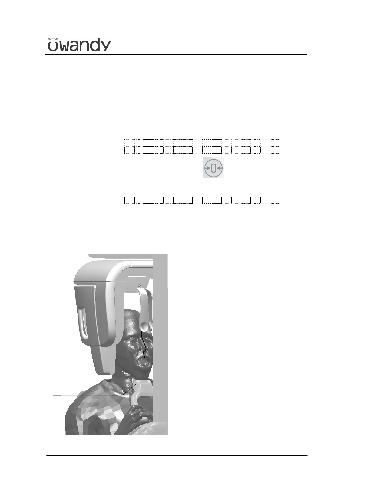
USER'S MANUAL
General instructions for use
I-Max Touch (110-120V) (Rev. 0)
66
6.6.4 TMJ open mouth
6.6.4.1 Preparation of the patient
1. The patient must be prepared following the operations described in
paragraph 6.6.3.1.
The following message will be displayed:
I N S T R U C T P A T I E N T
T O O P E N M O U T H !
2. Press the key "Patient Entrance" (6) to confirm.
The following message will be displayed:
x x k V x x m A 9 . 7 0 s
T M J O / C - > O P E N
x = value defined by the settings
3. Position the patient again if he has been removed from the centring
device. Tell him to open his mouth (helping him to keep in position
using appropriate mechanical devices - not supplied - if necessary)
and keep his chin touching the SINUS/TMJ chin support rest.
1
3
4
45
Figure 13 - Open mouth examination positioning
Legend of Reference Lines
45 Sagittal medial line
Legend positioning devices and
patient centring
1 SINUS/TMJ chin support
3 Temple clasps - Forehead
support
4 Temple clasps - Forehead
support release knobs
Page 72
USER'S MANUAL
General instructions for use
(Rev. 0) I-Max Touch (110-120V)
67
4. Instruct the patient to close his eyes.
5. Press the key "Centring devices ON" (14) .
Two laser beams will light up the sagittal medial plane line and the
horizontal line for the Frankfurt plane reference (Figure 10).
Using as reference the sagittal medial plane laser, position the
patient's head in such a way that the sagittal medial plane is lit by
the corresponding laser beam as in Figure 13.
The movement of the patient head due to the open mouth positioning
is automatically corrected by the software and should be not
necessary any column adjustment.
NOTE:
The laser centring device will stay lit up until the "Centring Devices ON"
(14) key or, at the end of the alignment, the key "Patient
Entrance" (6) is pressed to start the exposure.
6. Close the temple clasps and bring the forehead support close; this
will help the patient to stay in a correct position. Check that, during
this phase, the patient has not changed position.
7. Advise the patient to remain perfectly still and not look at the
rotating arm during the movements.
*
Page 73
USER'S MANUAL
General instructions for use
I-Max Touch (110-120V) (Rev. 0)
68
6.6.4.2 Carrying out the second exposure (mouth open)
WARNING:
During the emission of X-rays, the protection procedures for the operator
and personnel in the area must be in compliance with the local
regulations.
In all cases, it is recommended that during the emission of X-rays, only
the patient and operator be present in the room. If the operator is not
protected by suitable screens, he must stand at least 1.5 m (4.9 ft) away
from the emission of the rays (see the Figure 1 and Figure 2).
WARNING:
Using the laser centring devices, check that the system is still aligned
with the patient's sagittal medial plane.
1. Press the key "Patient Entrance" (6) . The display will show:
x x k V x x m A 9 . 7 0 s
S T A R T E X A M
Check again that the exposure data are correct (see paragraph 6.6.2).
NOTE:
The Adult/Child and Size small - medium - large selection keys are
deactivated. The exposure parameters can be changed as described in
paragraph 6.6.2.
Press the X-ray button for the entire duration of the exposure,
checking the concurrent working of the ray indicator light "X-ray
emission" (if you are within sight of the machine) and the acoustic
ray signal. The following message will be displayed first:
S T A R T E X A M
P R E - H E A T I N G . . .
and then (after 2 seconds), the following message will be
displayed:
x x k V x x m A 9 . 7 0 s
> X - R A Y <
x = value defined by the settings
*
Page 74
USER'S MANUAL
General instructions for use
(Rev. 0) I-Max Touch (110-120V)
69
NOTE:
The rotation of the arm and the emission of the X-rays will start with a
delay of 2 seconds from when the X-ray button is pressed. As the X-ray
button is a "dead man's switch", it is necessary to keep it pressed
until the end of the exposure.
During the examination, the emission of rays in correspondence with the
central part of the dental arch is suspended; the relative signals (sonant
and visual) are also suspended.
2. Once the exposure is completed, the system will rotate back. When it
has completed this manoeuvre, the display shows the message:
P A T I E N T E X I T
P R E S S > 0 <
and it will be necessary to free the patient from the positioning
device.
3. Press the "Patient Entrance" (6) key ; the machine will return
to the patient entry position and the following message will be
displayed:
P L E A S E W A I T . . .
WARNING:
After every examination, clean the chin support, the handles and
the temple clasps group thoroughly.
*
Page 75
USER'S MANUAL
General instructions for use
I-Max Touch (110-120V) (Rev. 0)
70
NOTE:
If, during the exposure, the patient moves, or the machine collides with
the patient himself (or with any object), or you realise that the
parameters set are not correct, you must release the X-ray button
immediately, interrupting the emission of X-rays and the movement of
the arm.
If this occurs, the following message will be displayed:
E 2 0 6
P R E S S > 0 <
All the motors will switch off, and it will be possible, if necessary, to
manually rotate the arm, allowing the patient to come out; it is
recommended that this movement be made with great care in order
to prevent damage to the machine.
Then press the "Patient Entrance" (6) key and the display
will show:
M A C H I N E S E T T I N G
P R E S S > 0 <
and then:
WA I T F O R
M A C H I N E S E T T I N G
The system now returns to its initial position and the patient must be
repositioned.
NOTE:
If the open mouth exposure is not completed, the closed mouth exposure
must be repeated or the four complete pictures will not appear.
*
*
Page 76
USER'S MANUAL
General instructions for use
(Rev. 0) I-Max Touch (110-120V)
71
6.7 SINUS examination
To select the SINUS examination, press key "Examination Mode
Selection" (10) until the following message and graphic is
displayed:
x x k V x x m A 9 . 4 0 s
S I N U S
x = value defined by the settings
During the examination, one single rotation of the rotating arm is to be
expected, with the X-rays emission limited to the interested area.
Page 77
USER'S MANUAL
General instructions for use
I-Max Touch (110-120V) (Rev. 0)
72
6.7.1 Anatomic / Manual Exposure
NOTE:
If the previous exam was carried out manually, just press the key "Size
Selection" (8) or the key "Examination Mode Selection"
(10) .
After setting the machine, it is possible to choose between the following
two operating modes:
• ANATOMIC: with the values of kV and mA programmed on the basis
of the type of patient and the size.
• MANUAL: with the possibility to vary the kV and mA values already
set.
NOTE:
In the manual mode, the "Anatomic/Manual mode" (13) indicator
displays "M" to indicate the manual mode; it is possible to use
key (7) to change from Adult to Child.
*
*
Page 78
USER'S MANUAL
General instructions for use
(Rev. 0) I-Max Touch (110-120V)
73
6.7.1.1 Anatomic exposure
Select the type of patient with the Adult/Child key (7).
Select the type of build with the Size (8) key (small - medium - large).
On the basis of the selections made, the display will visualise the kV and
mA settings as in the table.
Exposure values in SINUS examination (9.4 sec)
Adult Child
kV mA kV mA
Small 66 6 62 6
Medium 70 6 64 6
Large 72 6 66 6
Table 4
Page 79

USER'S MANUAL
General instructions for use
I-Max Touch (110-120V) (Rev. 0)
74
6.7.1.2 Manual exposure
If the kV and mA combinations of the Table 4 are not considered suitable
for a specific examination, it will be possible to set new parameters using
the manual mode.
To modify the kV or mA values, press any of the up (3) or down
(4) arrows of the KV or mA parameters, the blue frames around the
"Examination mode selection", the "Adult/Child Selection" (7) and the
"Size Selection" (8) keys will disappear, orange frames will appear around
the up and down arrow keys of the parameters (3) and (4) and the
"Anatomic/Manual mode" indicator will display "M". The display will
show respectively one of the following two indications:
> x x k V x x m A 9 . 4 0 s
S I N U S
or
x x k V > x x m A 9 . 4 0 s
S I N U S
The symbol ">" indicates which parameter is being changed.
A parameter can be modified by pressing the increase key (3)
and the decrease key (4) of that parameter repeatedly.
The kV value can vary between 60 and 86 kV, with 2 kV steps.
The value of mA can vary between 6 and 10 mA, with 1 mA steps.
NOTE:
To change the values rapidly, keep the increase key (3) or decrease key
(4) pressed.
*
Page 80
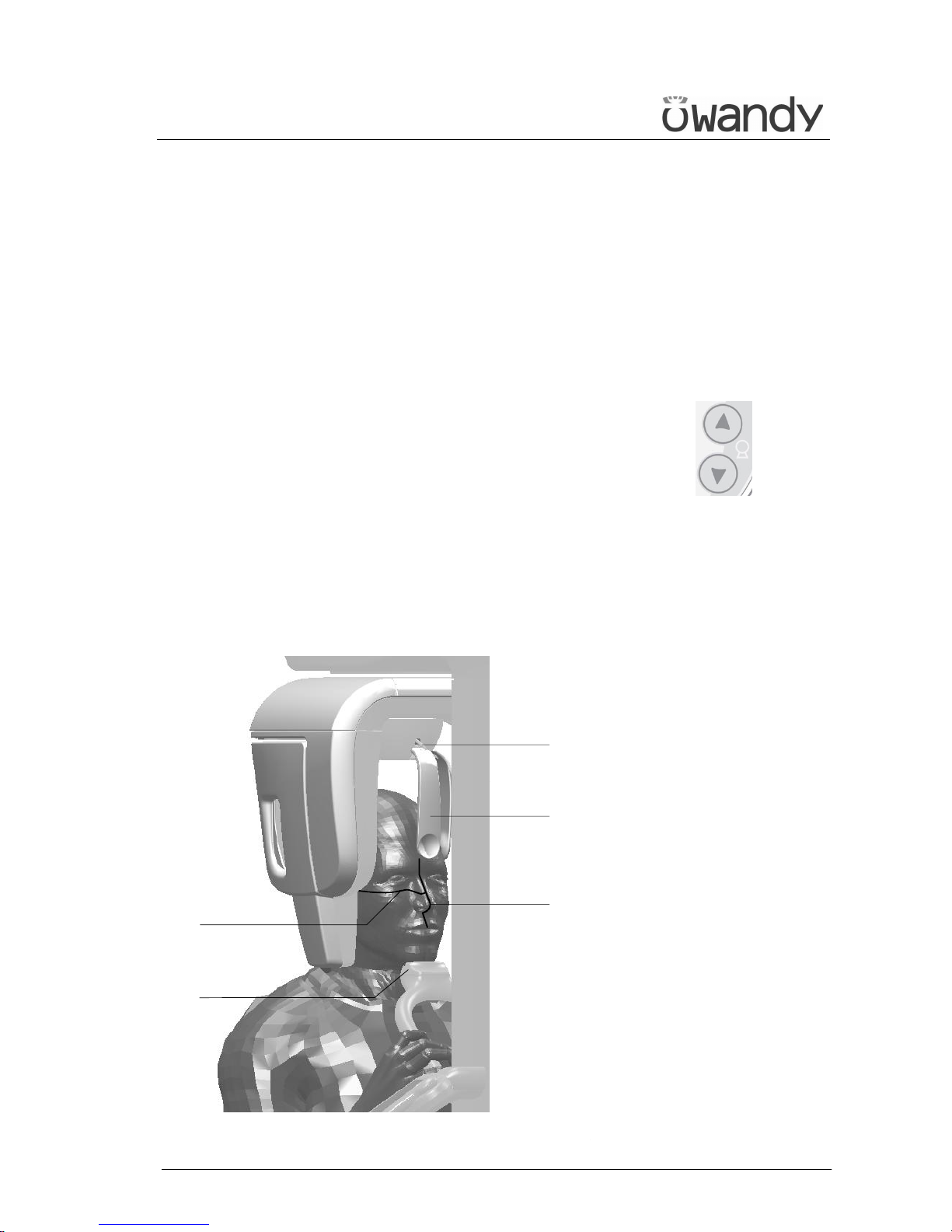
USER'S MANUAL
General instructions for use
(Rev. 0) I-Max Touch (110-120V)
75
6.7.2 Preparation of the patient
1. Ask the patient to remove all metallic objects located in the area to be
X-rayed (necklaces, earrings, glasses, hairpins, removable dental
prosthesis, etc.). Ensure that there are no thick garments in the area
to be X-rayed (coats, jackets, ties, etc.).
2. Ask the patient to put on the protective apron, or something similar,
making sure that it does not interfere with the trajectory of the X-ray
beams.
3. Place the patient in a standing position at the SINUS/TMJ chin
support. With the keys "Column movement" (15/16)
raise/lower the column until the chin support rest is aligned with the
patient's chin.
4. Position the patient with the temple clasps (Figure 14) ensuring that
the chin rests on the special support; ask the patient to place his
hands on the front supports. Ensure that the patient rests his chin
on the chin support for SINUS/TMJ.
1
3
4
45
46
Figure 14 - SINUS positioning
Legend of Reference Lines
45 Sagittal medial line
46 Frankfurt plane line
Legend positioning devices and
patient centring
1 SINUS/TMJ chin support
3 Temple clasps - Forehead
support
4 Temple clasps - Forehead
support release knobs
Page 81
USER'S MANUAL
General instructions for use
I-Max Touch (110-120V) (Rev. 0)
76
5. Instruct the patient to close his eyes.
6. Press the key "Centring devices ON" (14) .
Two laser beams will light up the sagittal medial plane line and the
horizontal line for the Frankfurt plane reference (the plane that
identifies a line that ideally links the ear hole - the auditory meatus with the lower part of the orbital fossa in Figure 10). Position the
patient's head in such a way as to ensure that the first two luminous
beams fall in correspondence with the respective anatomical
references.
The luminous beam of the Frankfurt plane can be adjusted according
to the patient's height; this can be adjusted by means of the laser
knob on the side of the mirror.
NOTE:
The laser centring device will stay lit up until the "Centring Devices ON"
(14) key or, at the end of the alignment, the key "Patient
Entrance" (6) is pressed to start the exposure.
7. Close the temple clasps and bring the forehead support close; this
will help the patient to stay in a correct position. Check that, during
this phase, the patient has not changed position.
8. Press the key "Patient Entrance" (6) to confirm.
The luminous centring devices switch off and the rotating arm goes
to its examination start position. Once alignment has been
completed, the following message will be displayed:
x x k V x x m A 9 . 4 0 s
S T A R T E X A M
x = value defined by the settings
9. Ask the patient to: close his mouth, remain perfectly still and
not look at the rotating arm during the movement.
*
Page 82
USER'S MANUAL
General instructions for use
(Rev. 0) I-Max Touch (110-120V)
77
6.7.3 Making an exposure
WARNING:
During the emission of X-rays, the protection procedures for the operator
and personnel in the area must be in compliance with the local
regulations. In all cases, it is recommended that during the emission
of X-rays, only the patient and operator be present in the room. If the
operator is not protected by suitable screens, he must stand at least
1.5 m (4.9 ft) away from the emission of the rays (see the Figure 1 and
Figure 2).
NOTE:
Before performing a lateral Sinus examination, because of the specific
trajectory described by the rotating arm, it is recommended to check for
possible mechanical interferences with the patient's shoulder during the
rotation.
By pressing the key "Test" (5) , to activate the Test function.
In this condition, it will be possible to make the machine perform all the
movements made during the examination, but without emitting rays.
Once the cycle is completed, deactivate the "Test" function by pressing
the key again.
1. Verify once again that the exposure data are correct. If not, correct
them as described in paragraph 6.5.2.2; ensure that the machine's
indicator light "Ready for X-ray" will come on, so press the X-ray
button for the entire duration of the exposure, checking the
simultaneous working of the ray indicator light "X-ray emission" (if
you are within sight of the machine) and the acoustic ray signal. The
following message will be displayed first:
S T A R T E X A M
P R E - H E A T I N G . . .
and then (after 2 seconds), the following message will be displayed:
x x k V x x m A 9 . 4 0 s
> X - R A Y <
x = value defined by the settings
NOTE:
If the machine is in the "Test" mode, the display will show:
T E S T
X R A Y N O T A C T I V E
*
*
Page 83
USER'S MANUAL
General instructions for use
I-Max Touch (110-120V) (Rev. 0)
78
NOTE:
The I-Max Touch assumes that the digital sensor is ready: if this is not
the case, the following error message will be displayed:
D I G I T A L S E N S O R
I S N O T R E A D Y
Refer to the Manual of the Digital Acquisition System to correct the
situation.
To reset the message on the I-Max Touch, press key .
NOTE:
The rotation of the arm and the emission of the X-rays will start with a
delay of 2 seconds from when the X-ray button is pressed. As the X-ray
button is a "dead man's switch", it is necessary to keep it pressed
until the end of the exposure.
During the examination, the emission of rays in correspondence with the
central part of the dental arch is suspended; the relative signals (sonant
and visual) are also suspended.
2. Once the exposure is completed, the system will rotate back. When it
has completed this manoeuvre, the display shows the message:
P A T I E N T E X I T
P R E S S > 0 <
and it will be necessary to free the patient from the positioning
device.
3. Press the key "Patient Entrance" (6) . The machine will
reposition itself back to the starting position displaying the message:
P L E A S E W A I T . . .
At the end, the following message is displayed:
x x k V x x m A 9 . 4 0 s
S I N U S
x = value defined by the settings
that shows the values set for that last exposure. A new exposure can
now be made.
*
*
Page 84
USER'S MANUAL
General instructions for use
(Rev. 0) I-Max Touch (110-120V)
79
NOTE:
If you try to perform a new exam before the cooling period has elapsed (4
minutes), the following message will be displayed indicating the time to
wait before performing a new examination:
T U B E C O O L I N G
P L E A S E W A I T x x x s
The waiting time allows the anode in the radiogenic tube to cool down.
WARNING:
After every examination, clean the chin support, the handles and
the temple clasps group thoroughly.
NOTE:
If, during the exposure, the patient moves, or the machine collides with
the patient himself (or with any object), or you realise that the
parameters set are not correct, you must release the X-ray button
immediately, interrupting the emission of X-rays and the movement of
the arm.
If this occurs, the following message will be displayed:
E 2 0 6
P R E S S > 0 <
all the motors will switch off, and it will be possible, if necessary, to
manually rotate the arm, allowing the patient to come out; it is
recommended that this movement be made with great care in order
to prevent damage to the machine.
Then press the "Patient Entrance" (6) key and the display
will show:
M A C H I N E S E T T I N G
P R E S S > 0 <
and then:
WA I T F O R
M A C H I N E S E T T I N G
The system now returns to its initial position and the patient must be
repositioned.
*
*
Page 85
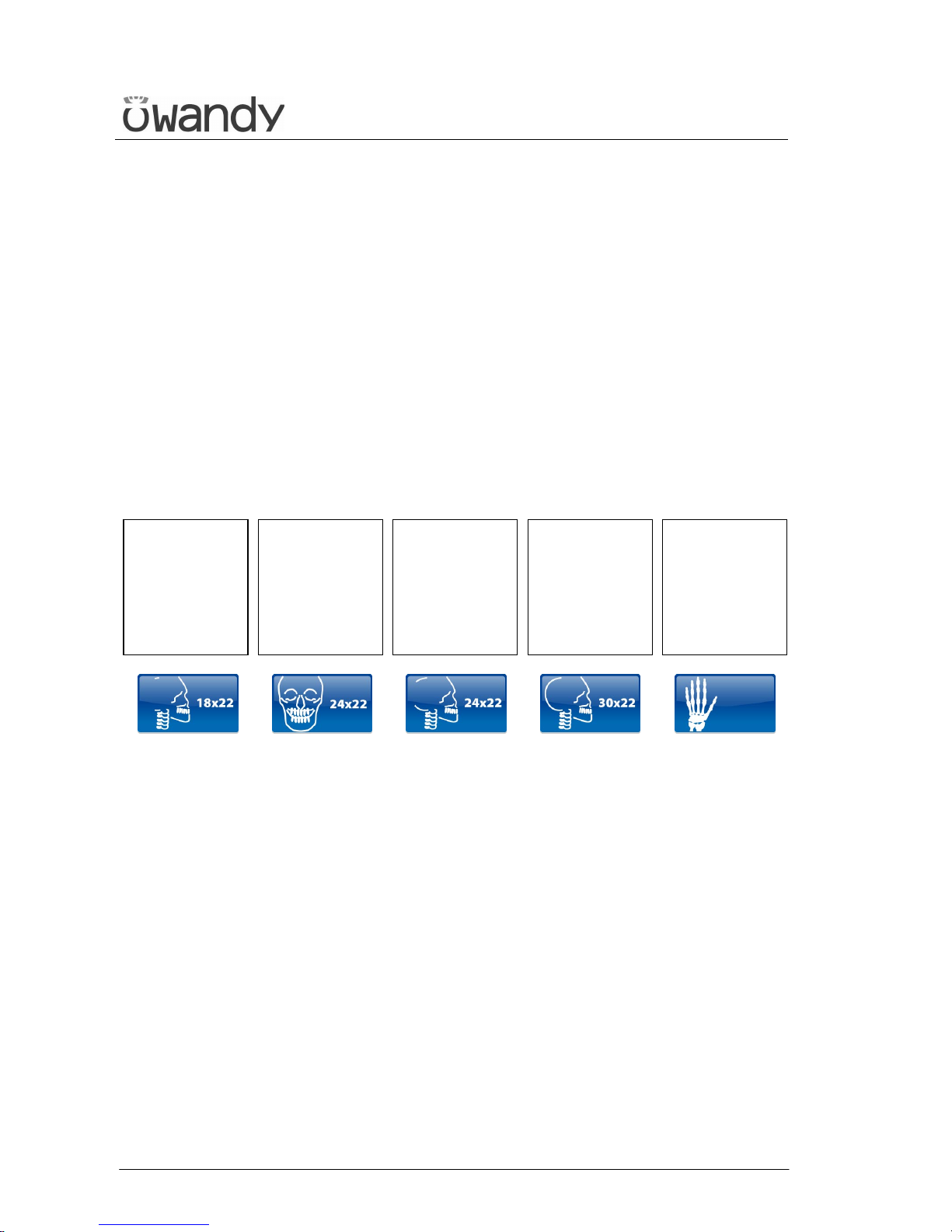
USER'S MANUAL
General instructions for use
I-Max Touch (110-120V) (Rev. 0)
80
6.8 Cephalometric examination
There is no rotation of the tube-head (X-ray generator) support arm and
sensor holder for the cephalometric examination.
Various projections are possible for the cephalometric examination. On
the basis of the image format selected and the projection chosen, the
primary diaphragm will automatically place itself in the correct position,
at the same time as the secondary collimator and the digital sensor.
The Cephalometric examination is fitted with a Soft Tissues Filter (STF);
this filter reduces the dose in areas with low bone content and highlights
the patient's profile which, under normal conditions, would be
overexposed and so not visible.
The I-Max Touch makes different kinds of exposures, according to the
type of selection made:
18x22
Asymmetric
for
Latero-Lateral
(L.L.)
24x22
Symmetric
for
Posterior-
Anterior (P.A.)
and Antero-
Posterior (A.P.)
24x22
Asymmetric
for
Latero-Lateral
(L.L.)
30x22
Symmetric
for
Latero-Lateral
(L.L.)
18x22
Symmetric
for assessment
of bone growth
(A.P.)
For all these formats, it is possible to carry out the examination in High
Resolution (h) or Normal Resolution (n).
It also possible to carry out the examination to assess bone growth,
following the instructions in paragraph 6.9 below.
Page 86
USER'S MANUAL
General instructions for use
(Rev. 0) I-Max Touch (110-120V)
81
6.8.1 Preparation of the device
To select the CEPH examination, press key "Examination Mode Selection"
(10) until the following message and graphic is displayed:
x x k V x x m A 4 . 5 0 s
C E 1 8 x 2 2 L L n 8 . 5
x = value defined by the settings
1. Press the "Patient Entrance" (6) key ; the display will show
alternatively the following messages:
C E P H - R E M O V E
C H I N R E S T
and
C E P H - C L O S E
T E M P L E S U P P O R T
The first message tells the operator to remove the chin support, while
the second message tells him to close the temple clasps. These
operations are necessary to prevent interference with the rays beam
and with the panoramic sensor holder when the arm is being
positioned.
WARNING:
Neither of the two messages are controlled by the system and they can
therefore appear even if the unit has been set correctly, until the "Patient
Entrance" (6) key is pressed.
WARNING:
There is no need to position any type of chin support for the
cephalometric examination. The chin support used for panoramic
examinations must be removed as indicated on the display. If the chin
support is not removed, it will collide with the sensor holder during
alignment and can obscure some anatomical parts of the patient during
the examination.
At the same time, the temple clasps must be closed, in order to avoid
collision with the rotating arm.
Page 87
USER'S MANUAL
General instructions for use
I-Max Touch (110-120V) (Rev. 0)
82
2. Once what was required is performed, press the key "Patient
Entrance" (6) ; messages will disappear and the machine will
align automatically with respect to the digital sensor and the
following message will be displayed:
A X I S P O S I T I O N I N G
P L E A S E W A I T . . .
NOTE:
In case of a single sensor unit, if the sensor holder is in PAN position,
once the alignment is completed, the following message will be displayed:
R E M O V E S E N S O R
I N P A N S L O T
Move the sensor in CEPH position folloing instruction in paragraph 6.2
and wait some seconds before to press "Patient Entrance" (6) key.
NOTE:
In case of a double sensor unit, once the alignment is completed, the
following message will be displayed:
C E P H - O P E N
C A S S E T T E H O L D E R
requesting the operator to open the sensor holder for panoramic
examination.
NOTE:
The position of the sensor holder for panoramic examination is controlled
by two micro-switches, it must therefore be completely opened.
The following message will be displayed:
x x k V x x m A 4 . 5 0 s
C E 1 8 x 2 2 L L n 8 . 5
This message indicates the image format predefined by the system;
the letter "n" after the format indicates that the execution will be in
Normal Resolution.
*
*
*
Page 88
USER'S MANUAL
General instructions for use
(Rev. 0) I-Max Touch (110-120V)
83
You can pass from Normal Resolution (indicated by the letter "n") to
High Resolution (indicated by the letter "h"), by pressing key
"Examination Mode Selection" (10) and viceversa.
Pressing twice the key (10) the unit will return to
PANORAMIC STD position; the display shows:
C O NF I M P AN?
> 0 < = S , T = N
Pess the "Patient Entrance" (6) key to confirm or the "Test" (5)
Key to cancel the setting.
NOTE:
With the same image format, the scanning time is lower in Normal
Resolution; this allows you to give the patient a smaller dose, yet still
obtaining an image of sufficient quality for the orthodontic diagnostics,
albeit with a spatial resolution lower compared with that obtained from
High Resolution images.
NOTE:
The system is positioned in the following configuration:
• ADULT with the display of the corresponding graphic in the button
• MEDIUM SIZE with the display of the corresponding graphic in the
button.
The key "Type of Biting Selection" (9) is disabled.
3. By means of the keys "Arrow right" (12) and "Arrow left" (11)
select the dimensions of the image and the type of projection (see the
table at the beginning of the Chapter).
*
*
Page 89
USER'S MANUAL
General instructions for use
I-Max Touch (110-120V) (Rev. 0)
84
6.8.2 Anatomic / Manual Exposure
NOTE:
If the previous exam was carried out manually, just press the key
"Examination Mode Selection" (10) to change to Anatomic
exposure.
In this case, pressing selection key does not modify the choise of
resolution, which is modified by pressing the same key again.
After setting the machine accordingly, the following two operating modes
may be selected:
• ANATOMIC: with the kV and mA values programmed according to
the type of patient and size; Soft Tissue Filter in default position
• MANUAL: with the possibility of changing the kV, mA and Soft Tissue
Filter values set (mm).
NOTE:
In the manual mode, the "Anatomic/Manual mode" (13) indicator
displays "M" to indicate the manual mode; it is possible to use
key (7) to change from Adult to Child.
*
*
Page 90
USER'S MANUAL
General instructions for use
(Rev. 0) I-Max Touch (110-120V)
85
6.8.2.1 Anatomic exposure
Select the type of patient with the Adult/Child key (7).
Select the type of build with the Size (8) key (small - medium - large).
The kV and mA values will be displayed according to the selections made
as per the following tables:
Adult Child
kV mA kV mA
Small 66 6 62 6
Medium 70 6 64 6
Large 72 6 66 6
Table 5: Latero-Lateral projection
Adult Child
kV mA kV mA
Small 74 12 70 10
Medium 76 12 72 10
Large 80 10 74 10
Table 6: Antero-Posterior projection
Page 91
USER'S MANUAL
General instructions for use
I-Max Touch (110-120V) (Rev. 0)
86
6.8.2.2 Manual exposure
If the kV and mA combinations in the table Table 5 are not considered
suitable for a specific examination, it will be possible to set new
parameters using the manual mode.
NOTE:
It will be possible to modify manually kV, mA and Soft Tissue Filter
position (mm).
The "mm" value in the exposure parameters and parameter "fxx.x" in the
display indicate the position of the STF; it has to be adjusted according to
the value read on the graduate scale present on the nose rest (Figure 15).
To modify the kV, mA and STF values, press any of the up (3) or
down (4) arrows of the KV, mA or mm parameters, the blue frames
around the "Examination mode selection", the "Adult/Child Selection" (7)
and the "Size selection" (8) will disappear, orange frames will appear
around the up and down arrow keys of the parameters (3) and (4) and the
"Anatomic/Manual mode" indicator will display "M". The display will
show respectively one of the following three indications:
> x x k V x x m A x x . x s
C E 1 8 x 2 2 L L n 8 . 5
x x k V > x x m A x x . x s
C E 1 8 x 2 2 L L n 8 . 5
x x k V x x m A > f x x . x
C E 1 8 x 2 2 L L n 8 . 5
The symbol ">" indicates which parameter is being changed.
A parameter can be modified by pressing the increase key (3)
and the decrease key (4) of that parameter repeatedly.
The "kV" value can vary between 60 and 80 kV, with 2 kV steps.
The "mA" value can vary between 4 and 12 mA, with 1 mA steps.
The "Soft Tissue Filter" value can vary between 6 and 10.5 cm, with
0.1 cm steps.
NOTE:
To change the values rapidly, keep the increase key (3) or decrease key
(4) pressed.
*
*
Page 92
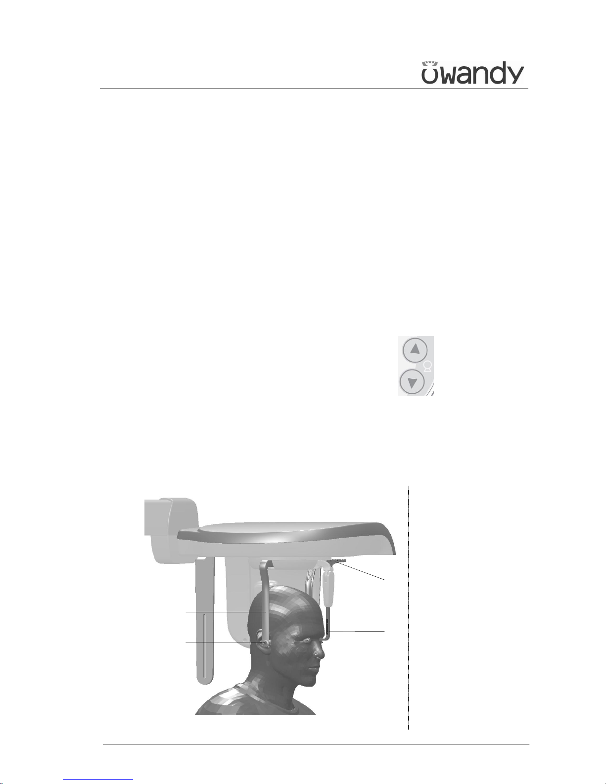
USER'S MANUAL
General instructions for use
(Rev. 0) I-Max Touch (110-120V)
87
6.8.3 Preparation of the patient
1. Ask the patient to remove all metallic objects located in the area to be
X-rayed (necklaces, earrings, glasses, hairpins, removable dental
prosthesis, etc.). Ensure that there are no thick garments in the area
to be X-rayed (coats, jackets, ties, etc.).
2. Ask the patient to put on the protective apron, or something similar,
making sure that it does not interfere with the trajectory of the X-ray
beams.
3. Open the ear centring device (Figure 15) to its maximum span by
using the upper part of the rods of the centring device itself. Move the
nose rest (Figure 15) away outwardly to its maximum extension.
Manually rotate the craniostat group according to the cephalometric
projection to be made, moving the upper part of the ear centring
device (Figure 15).
4. Position the patient upright near the auricular centring device.
With the keys "Column movement" (15/16) lift/lower, the
column till the centring pins (Figure 15) are close to the ear to clasp
the patient's head so that the pivots penetrate the ear (Figure 15)
moving the upper part of the rods.
If a Latero-Lateral examination is performed, position the nose rest.
5. By selecting an "asymmetric" projection, the Soft Tissues Filter (STF)
will be automatically inserted.
2
3
1
4
Figure 15
Legend
1 Nose rest
2 Ear centring device
3 Pins for ear centring
device
4 Nose rest graduate
scale
Page 93
USER'S MANUAL
General instructions for use
I-Max Touch (110-120V) (Rev. 0)
88
6.8.4 Making an exposure
WARNING:
During the emission of X-rays, the protection procedures for the operator
and personnel in the area must be in compliance with the regulations in
force in the country where the machine is used.
In all cases, it is recommended that during the emission of X-rays, only
the patient and operator be present in the room. If the operator is not
protected by suitable screens, he must stand at least 1.5 m (4.9 ft) away
from the emission of the rays (see Figure 1 and Figure 2).
1. Verify once again that the exposure data are correct (see paragraph
6.8.2). Advise the patient to remain still and to keep his mouth
closed, with the teeth touching, throughout the duration of the
exposure.
Press the "Patient Entrance" (6) key .
The unit will move into the selected examination start position.
The signalling LED "Ready for X-ray" will light up, indicating that the
machine is ready to produce X-rays.
NOTE:
If you want to cancel the operation, press key "Patient Entrance" (6)
2. Press the X-ray button for the entire duration of the exposure,
checking the concurrent working of the ray indicator light "X-ray
emission" (if you are within sight of the machine) and the acoustic
ray signal.
The following message will be displayed first:
S T A R T E X A M
P R E - H E A T I N G . . .
and then (after 2 seconds), the following message will be displayed:
x x k V x x m A x . x x s
> X - R A Y <
x = value defined by the settings
*
Page 94
USER'S MANUAL
General instructions for use
(Rev. 0) I-Max Touch (110-120V)
89
NOTE:
The I-Max Touch assumes that the digital sensor is ready: if this is not
the case, the following error message will be displayed:
D I G I T A L S E N S O R
I S N O T R E A D Y
Refer to the Manual of the Digital Acquisition System to correct the
situation.
To reset the message on the I-Max Touch, press key .
NOTE:
X-rays are emitted with a delay of two seconds from pressing the X-ray
button to allow the heating of the filament and the control of all set
parameters. Since the X-ray button is a "dead man’s switch", it must
be kept pressed until the end of the exposure.
3. Once the exposure is completed, the secondary collimator moves into
a back resting position, to allow the patient to come out.
The display will again show all the exposure values relating to the
exposure just completed.
NOTE:
If you want to carry out a new exposure, but the necessary waiting time
for the cooling of the anode hasn't yet passed, the display will show a
message indicating the time you still have to wait before carrying out the
new test:
T U B E C O O L I N G
P L E A S E W A I T x x x s
This time enables the X-ray tube's anode to cool down.
*
*
*
Page 95
USER'S MANUAL
General instructions for use
I-Max Touch (110-120V) (Rev. 0)
90
NOTE:
If the patient moves during the exposure, or if you realise that incorrect
parameters have been set, it will be necessary to stop pressing the X-ray
button immediately, to interrupt the emission of rays.
The following message will be displayed:
E 2 0 6
P R E S S > 0 <
Then press the "Patient Entrance" (6) key .
The system now returns to the position for Ceph exam and the unit
starts the procedure for the new examination.
NOTE:
After every examination, clean the ear centring device and temple
clasps group thoroughly.
*
*
Page 96

USER'S MANUAL
General instructions for use
(Rev. 0) I-Max Touch (110-120V)
91
6.9 Examination to assess bone growth (Carpus)
The cephalometric device can also be used to carry out X-rays to evaluate
the state of calcification and bone growth, X-raying the hand/wrist
complex to obtain an X-ray that contains the anatomic details necessary
to evaluate the patient's bone growth trend.
The image format set in order to carry out this examination is 18x22
Symmetric, not adjustable; it is therefore necessary to position the
auricular rods and the nose-rest as for the cephalometric AnteroPosterior examination, so that these elements do not interfere with the
X-ray trajectory. Refer to Figure 16.
Page 97
USER'S MANUAL
General instructions for use
I-Max Touch (110-120V) (Rev. 0)
92
6.9.1 Preparation of the device
1. Select the CEPH examination, pressing key "Examination Mode
Selection" (10) until the following message and graphic is
displayed:
x x k V x x m A 4 . 5 0 s
C E 1 8 x 2 2 L L n 8 . 5
x = value defined by the settings
2. By means of the keys "Arrow right" (12) and "Arrow left" (11)
select the CARPUS examination:
x x k V x x m A 4 . 5 0 s
C A R P U S 1 8 x 2 2 n
3. Press the "Patient Entrance" (6) key ; the display will show
alternatively the following messages:
C E P H - R E M O V E
C H I N R E S T
and
C E P H - C L O S E
T E M P L E S U P P O R T
The first message tells the operator to remove the chin support, while
the second message tells him to close the temple clasps. These
operations are necessary to prevent interference with the rays beam
and with the panoramic sensor holder when the arm is being
positioned.
WARNING:
Neither of the two messages are controlled by the system and they can
therefore appear even if the unit has been set correctly, until the "Patient
Entrance" (6) key is pressed.
WARNING:
There is no need to position any type of chin support for the Carpus
examination. The chin support used for panoramic examinations must be
removed as indicated on the display. If the chin support is not removed,
it will collide with the sensor holder during alignment and can obscure
some anatomical parts of the patient during the examination.
At the same time, the temple clasps must be closed, in order to avoid
collision with the rotating arm.
Page 98
USER'S MANUAL
General instructions for use
(Rev. 0) I-Max Touch (110-120V)
93
4. Once what was required is performed, press the key "Patient
Entrance" (6) ; messages will disappear and the machine will
align automatically with respect to the digital sensor and the
following message will be displayed:
A X I S P O S I T I O N I N G
P L E A S E W A I T . . .
NOTE:
In case of a single sensor unit, if the sensor holder is in PAN position,
once the alignment is completed, the following message will be displayed:
R E M O V E S E N S O R
I N P A N S L O T
Move the sensor in CEPH position following instruction in paragraph 6.2
and wait some seconds before to press "Patient Entrance" (6) key.
NOTE:
In case of a double sensor unit, once the alignment is completed, the
following message will be displayed:
C E P H - O P E N
C A S S E T T E H O L D E R
requesting the operator to open the sensor holder for panoramic
examination.
NOTE:
The position of the sensor holder for panoramic examination is controlled
by two micro-switches, it must therefore be completely opened.
The following message will be displayed:
x x k V x x m A 4 . 5 0 s
C A R P U S 1 8 x 2 2 n
This message indicates the image format predefined by the system;
the letter "n" after the format indicates that the execution will be in
Normal Resolution.
*
*
*
Page 99
USER'S MANUAL
General instructions for use
I-Max Touch (110-120V) (Rev. 0)
94
You can pass from Normal Resolution (indicated by the letter "n") to
High Resolution (indicated by the letter "h"), by pressing key
"Examination Mode Selection" (10) and viceversa.
Pressing twice the key (10) the unit will return to
PANORAMIC STD position; the display shows:
C O N F I M P A N ?
> 0 < = S , T = N
Pess the "Patient Entrance" (6) key to confirm or the "Test" (5)
key to cancel the setting.
NOTE:
With the same image format, the scanning time is lower in Normal
Resolution; this allows you to give the patient a smaller dose, yet still
obtaining an image of sufficient quality for the orthodontic diagnostics,
albeit with a spatial resolution lower compared with that obtained from
High Resolution images.
5. Regulate the exposure parameters as required, using the pre-set
values or manual selection; the display will show the kV and mA
settings as per the following table.
Child
kV mA
Small 60 6
Medium 60 6
Large 60 6
Table 7
*
Page 100
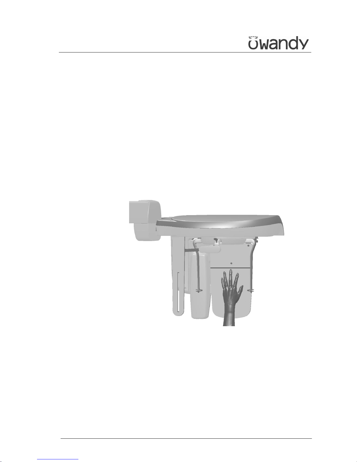
USER'S MANUAL
General instructions for use
(Rev. 0) I-Max Touch (110-120V)
95
6.9.2 Preparation of the patient
1. Turn the ear centring device to the Antero-Posterior position; bring
the nose-rest to a parking position.
2. Hook up the plastic positioning support for hand projection.
3. Place the patient slightly to the side of the cephalometry device.
4. Position the patient's hand on the positioning support (Figure 16).
The support leads the operator to place the body part in the centre of
the irradiated area. The horizontal line should help the vertical
adjustment of the hand.
The common radiological procedure to assess bone growth in
children, suggests placing the end of the middle finger tangent to the
reference line.
The patient's hand and arm must form a vertical line.
Figure 16
 Loading...