

Page 1

Wireless-G PCI Adapter
User’s Manual
Page 2

Table of Contents
1. Introduction
1.1The Wireless-G PCI Adapter
1.2 Key Feature
2. Planning Your Wireless Network
2.1 Network Topology
2.2 Ad-Hoc versus Infrastructure Mode
3. Getting to Know the Wireless-G PCI Adapter
4. Installing Driver, Configuration Utility and Hardware for Windows 98SE/ME/2000/XP
5. Using the Configuration Utility for Windows 98SE/ME/2000/XP
5.1 Overview
5.2 Access the Configuration Utility
5.3 Profile
5.4 Create a New Profile
5.5 Link Status
5.6 Site Survey
5.7 Statistics
5.8 Advanced
5.9 About
Page 3

1. Introduction
1.1 The Wireless-G PCI Adapter
The Wireless-G PCI Adapter can be installed in most desktops and provides true flexibility by
allowing the computer to be positioned almost anywhere in the building without the cost and
hassle of running network cables. Using the wireless PCI adapter, you don't have to worry about
drilling holes in your walls and climbing through the attic or cellar to get connected to the network.
Once installed and connected, you can keep in touch with friends and work through e-mail, instant
messaging and chat rooms as well as sharing files and other network resources such as printers
and network storage with other computers.
The Wireless-G PCI Adapter connects to 802.11g networks at an incredible speed of 54Mbps and
for added versatility; it can also interoperate with all Wireless-B (802.11b) products found in homes,
businesses, and public wireless hotspots around the country. In either mode, wireless
communications are protected by WEP and advanced WPA encryption levels.
1.2 Key Features
◆ 5 Times Faster and seamless operation with existing Wireless-B networks
◆ 64/128-bit WEP and 256-bit WPA (Wi-Fi Protected Access) Encryption Provides Maximum
Wireless Security
◆ Ease of Use through a Simple Setup Wizard
◆ Compatible with Windows 98SE/ME/2000/XP
Page 4
2. Planning Your Wireless Network
2.1 Network Topology
A wireless local area network (WLAN) is exactly like a regular local area network (LAN), except
that each computer in the WLAN uses a wireless device to connect to the network. Computers in a
WLAN share the same frequency channel and SSID, which is an identification name for wireless
devices.
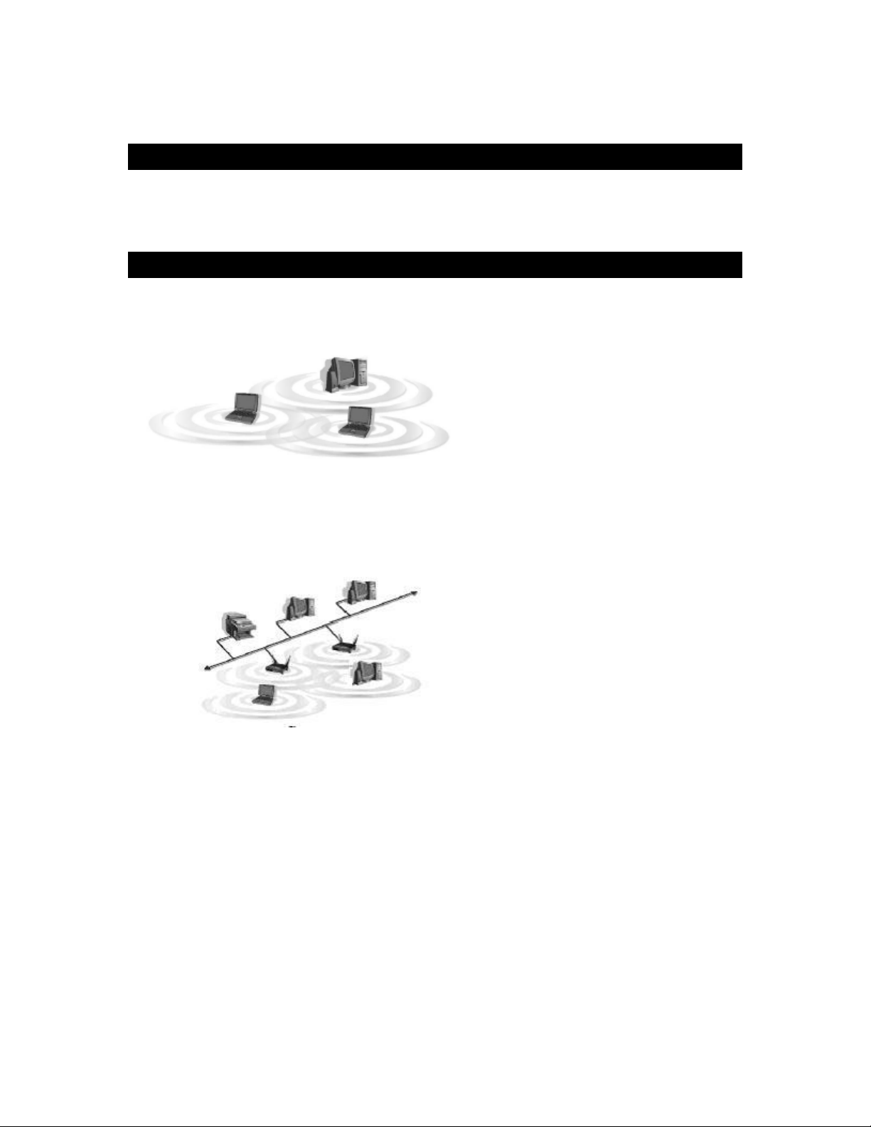
2.2 AD-Hoc versus Infrastructure Mode
Ad-Hoc wireless LAN is a group of computers, each equipped with one WLAN adapter,
An
connected as an independent wireless LAN. Computers in a specific Ad-Hoc wireless LAN must
all be configured to share the same radio channel.
An integrated wireless and wired LAN is called an
group of wireless nodes and an Access Point compose a Basic Service Set (BSS). Each PC
adapter/card in a BSS can talk to any computer in the wired LAN infrastructure via the Access
Point.
Infrastructure configuration. In this mode, a
Page 5

3. Getting to Know the Wireless-G PCI
Adapter
Wireless-G PCI Adapter installs into desktops like any other PCI Adapter. The two indicator lights
on the mounting bracket of the card are:
Ready LED Green. The Ready LED will light up when the card links to a wireless device.
ACT LED Green. The ACT LED will blink when the card transmits/receives data.
Page 6
4. Installing Driver, Configuration Utility and
Hardware for Windows 98SE/ME/2000/XP
4.1 Driver Installation for Windows 98SE/ME/2000/XP
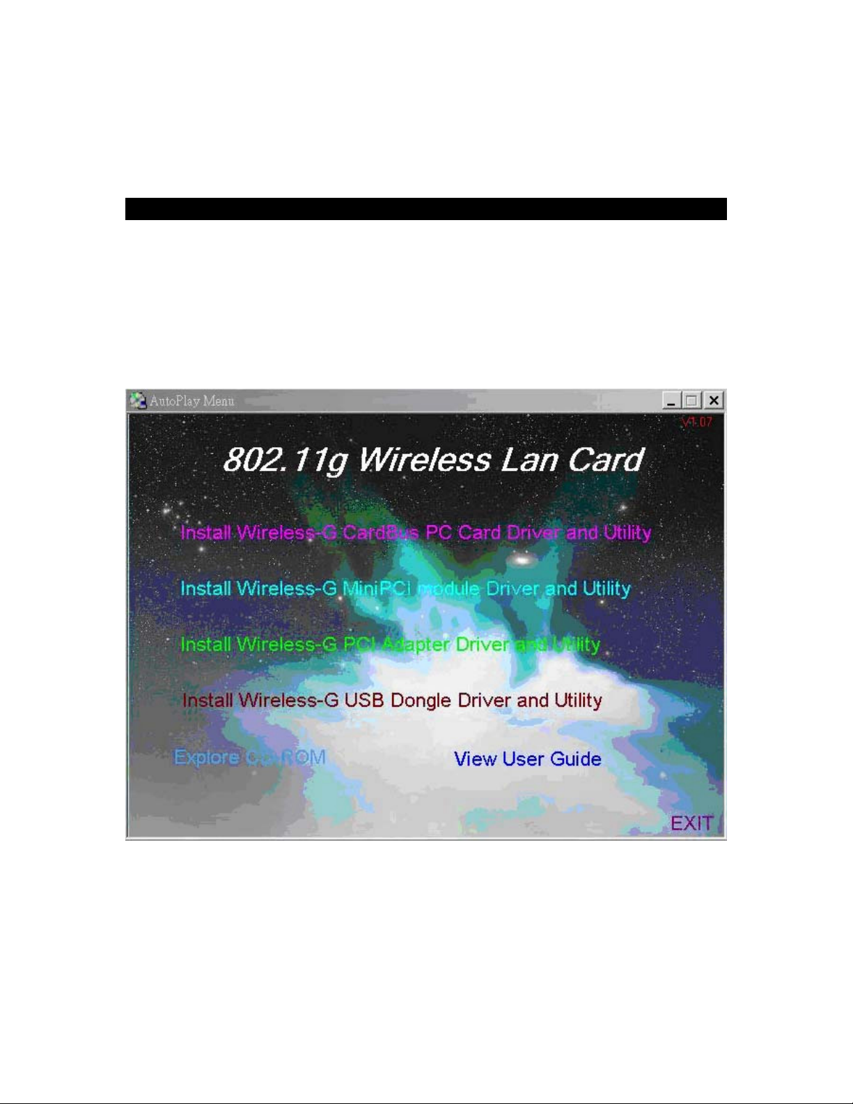
4.1.1 Running the Auto Install CD
Before installing your Wireless-G PCI Adapter, insert the Auto-Install CD into your CD-ROM
drive. Unless you have disabled the auto-run feature of Windows, the screen shown in Fig 4-1
should appear automatically. If not, you can manually access the installation by clicking the
Start button and choosing Run. In the drop-down box type D:\Setup.exe (where D: is the
letter of your CD-ROM drive).
Alternately, double-click My Computer and double-click on the CD drive (Setup.exe) icon.
Fig 4-1
Page 7
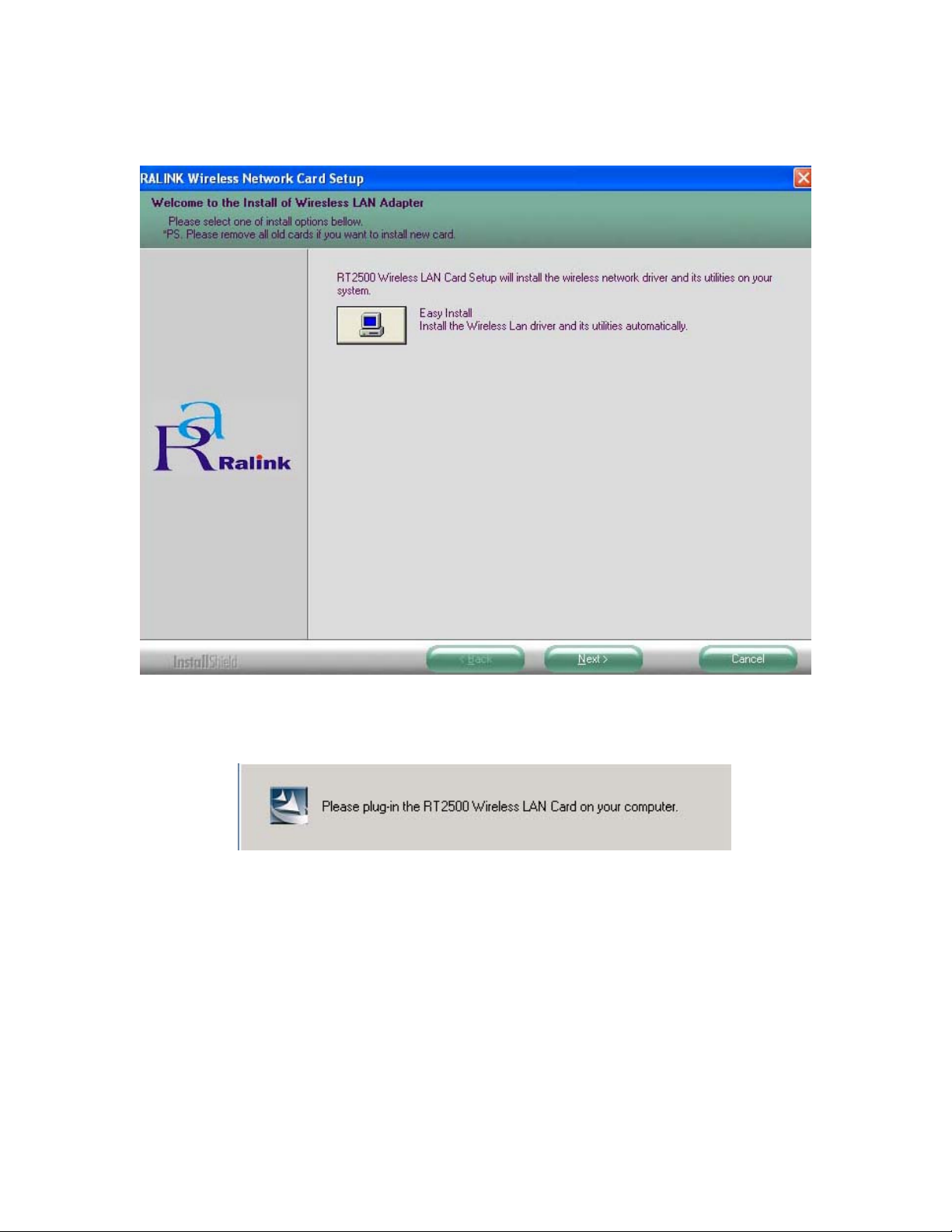
4.1.2 Click Install Wireless-G PCI Adapter Driver and Utility to install driver/utility for your
Wireless-G PCI Adapter. Click Next >. ( Fig 4-2)
Fig 4-2
4.1.3 During the installation, a message pops up asking for the wireless card to be plugged in
(Fig 4-3). Please ignore this message and proceed to the next step.
Fig 4-3
Page 8
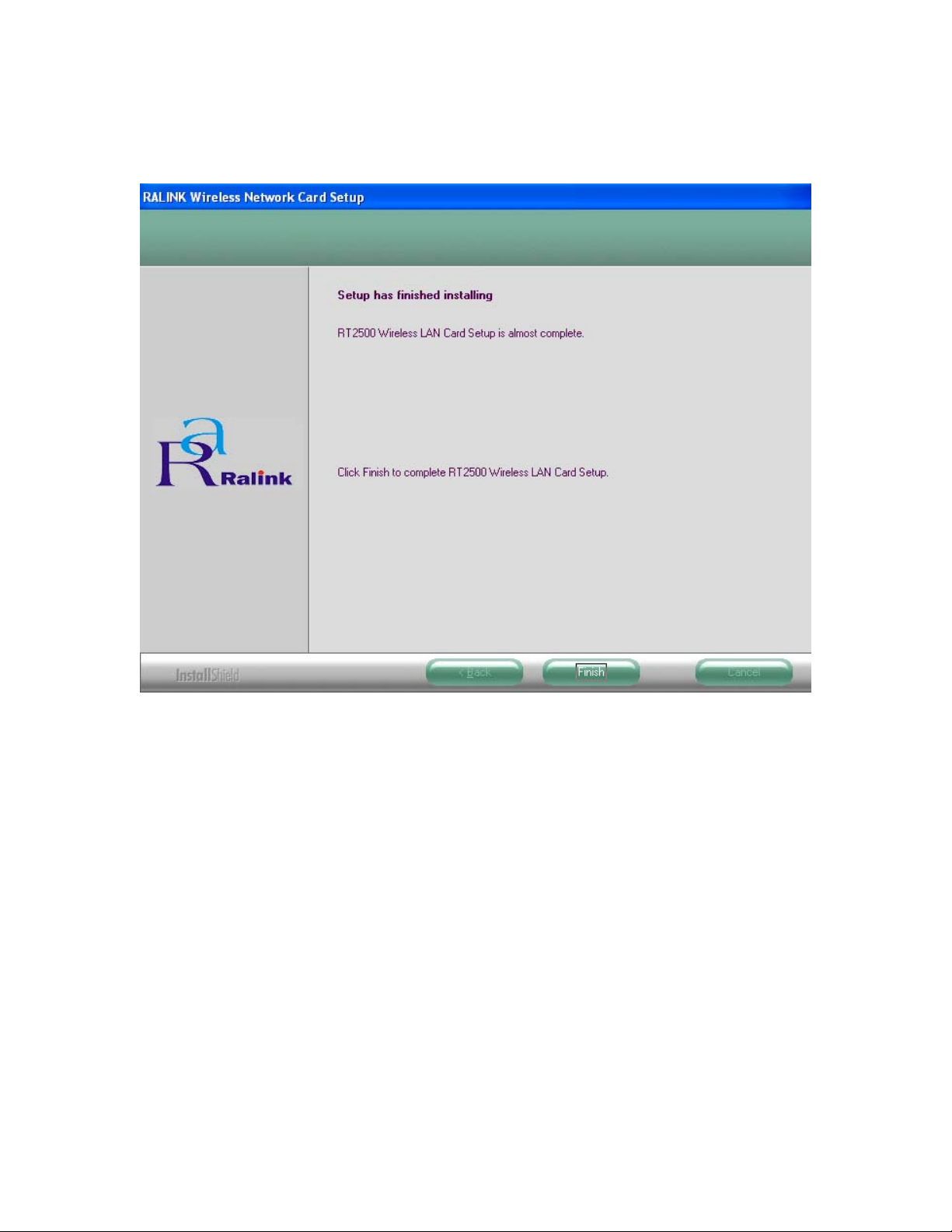
4.1.4 In Windows XP and 2000, in the page, click Finish (Fig 4-4) to complete the installation.
When installing in Windows ME and 98SE, In the page, select Yes, I want to restart my
computer now and Finish (Fig 4-5) to complete the installation and restart the PC.
Fig 4-4
Page 9

Fig 4-5
Page 10

4.2 Insert the Wireless-G PCI Adapter
4.2.1 To insert the Wireless-G PCI Adapter into a desktop computer, do the following:
Turn off your computer.
Open the case and locate an available PCI slot on the motherboard. Check with computer
manufacturer for instructions.
Slide the PCI Adapter into the PCI slot. Make sure that all its pins are touching the slot's
contacts. You may have to apply a bit of pressure to slide the adapter all the way in. After the
adapter is firmly in place, secure its fastening tab to your PC's chassis with a mounting screw
and close the case.
Attach the external antenna to the adapter’s antenna connector.
Power on your desktop PC.
4.2.2 Windows will automatically detect the adapter and complete the Wireless-G PCI Adapter
installation automatically.
(Note: Under Windows ME and Windows 98SE, Windows will ask you to restart your
computer, just click Yes to restart.)
Page 11

5. Using the Configuration Utility for
98SE/ME/2000/XP
5.1 Overview
The wireless Configuration Utility can be used to check link information, search for available
wireless networks, or to create profiles that hold different configuration settings.
5.2 Access the Configuration Utility
Before using the Configuration Utility, go to Start menu at the left-bottom side of the desktop, then
select Programs > Ralink > RT2500 > CCS, the Country Channel Select window appears.
(Fig 5-0) Then select the country Region and click OK.
Fig 5-0
The Configuration Utility icon will appear in your system tray. Double-click the icon. (Fig 5-1)
Fig 5-1
The utility is divided into six parts: Profile, Link Status, Site Survey, Statistics, Advance, and
About. You should change all your configuration settings for your Wireless-G PCI Adapter by
using this utility and not with the Network Properties section in your Control Panel.
Note: In Windows XP, you should disable the Wireless Zero Configuration service following the
steps below:
A. Right Click My Computer on the desktop and select Manage. (Fig 5-2).
Page 12
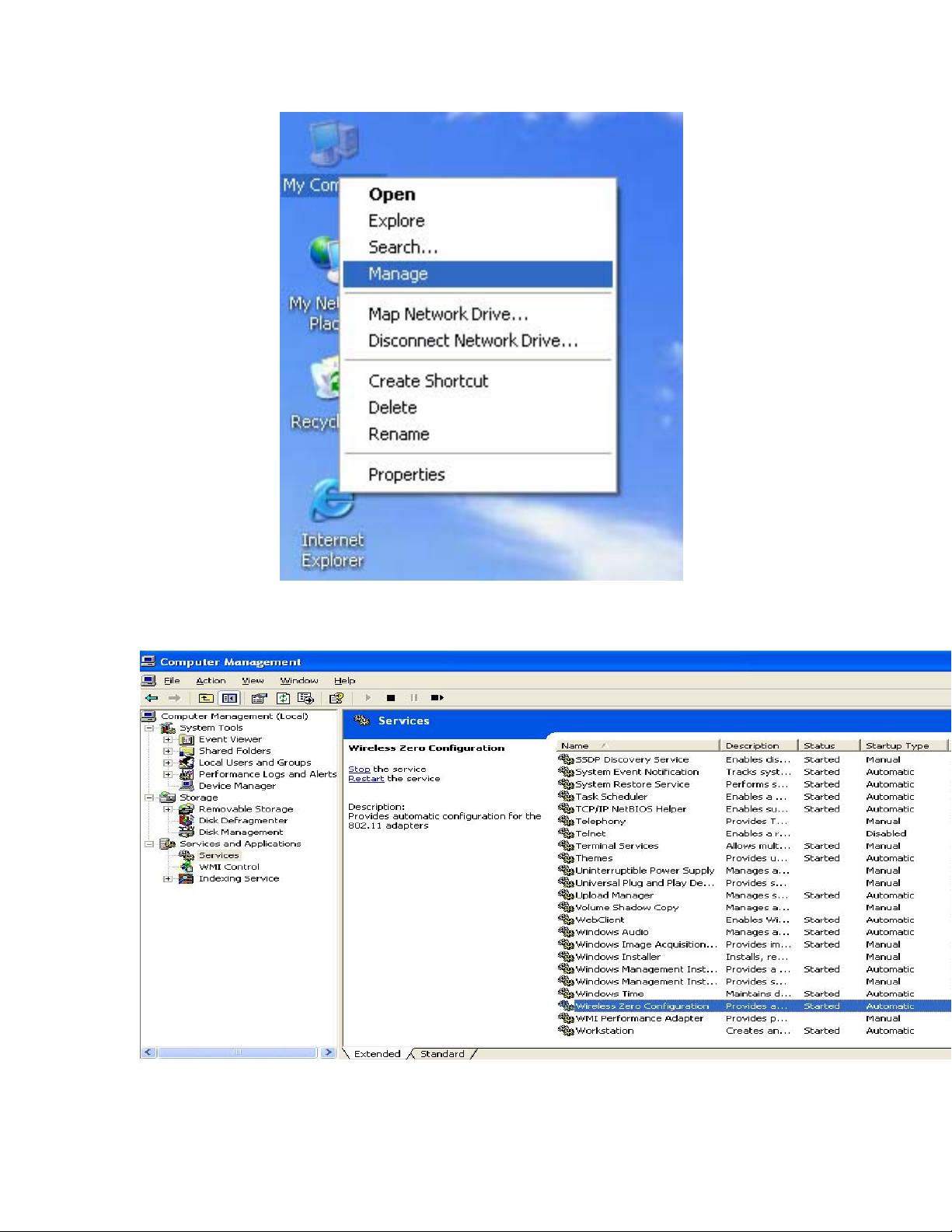
Fig 5-2
B. The Computer Management window comes up. Select Services from the Services and
Applications menu. Scroll down to locate Wireless Zero Configuration service.(Fig 5-3)
Fig 5-3
C. Double Click on Wireless Zero Configuration to go into its properties (Fig 5-4). For Startup
type, choose Disable to disable the Wireless Zero Configuration then click Apply and OK to
make the changes effective. Now you can use our Configuration Utility rather than Windows XP
Page 13
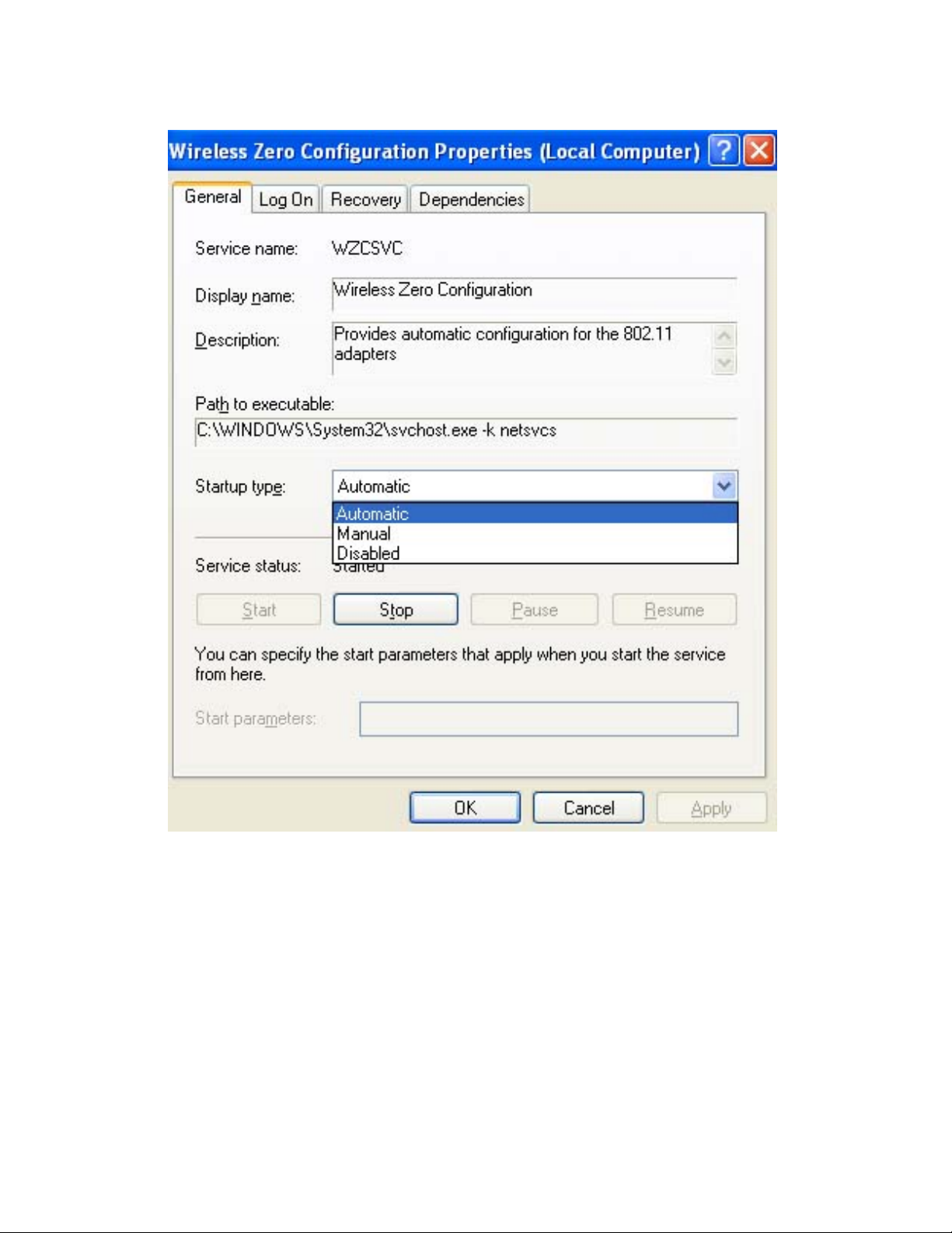
Wireless Zero Configuration Utility.
Fig 5-4
Page 14

5.3 Profile
The Profile screen (Fig 5-5) allows configuring and saving different configuration profiles for
different network setups.
Fig 5-5
Profile Name – Connection profile name.
SSID – SSID used for this profile.
Channel – The channel which the wireless network devices are set on.
Authentication – The Authentication method used in this profile.
Encryption – The Encryption type used for this profile.
Network Type – The Network type used for this profile.
Add- Click Add to create a new profile. Please refer to “5.4 Create a New Profile”.
Delete - Click the Delete button to delete a selected profile.
Edit- Select a profile, and click the Edit button to change an existing profile.
Activate- To activate a specific profile, select the profile, and click the Activate button.
Page 15

5.4 Create a New Profile
1- Enter the Profile Name.
Fig 5-6
2- Fill in the page with the following information.
SSID: Enter the SSID for the wireless network.
Network Type: There are two wireless modes.
(A) Infrastructure - This mode allows wireless and wired networks to communicate through an
access point.
(B) Ad-Hoc - This mode allows wireless-equipped computers to communicate directly with each
other.
3- Setup the Security Configuration
Page 16
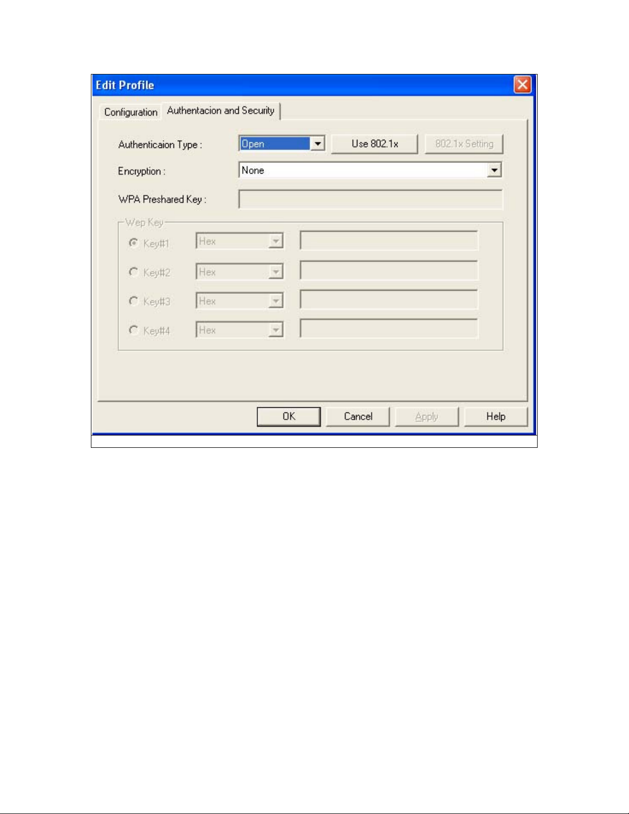
Fig 5-7
A. If encryption is not required; please click “OK” to save the profile.
Page 17

For configuring encryption, please follow the steps below:
B. WEP
1. Select Authentication type: Open System or Shared Key.
2. Select the key number that will be used
3. Enter the key
4. Click “OK” to save the profile. Please see Fig 5-8.
You can enter the WEP keys in either HEX or ASCII format. Select the preferred format and then
enter the key values in the Key #1-4 fields. Note that when using HEX format, only digits 0-9
and letters A-F are allowed. Valid key length for each encryption type is as below:
HEX Format ASCII Format
64 Bit 10 hexadecimal characters 5 ASCII characters
128 Bit
26 hexadecimal characters
13 ASCII characters
Fig 5-8
Page 18

C. WPA
1. Select Authentication type: WPA
2. Select Encryption type: TKIP or AES. Please see Fig 5-9
Fig 5-9
Page 19

3. Click “802.1x Setting” button. Please see Fig 5-10
Fig 5-10
Page 20
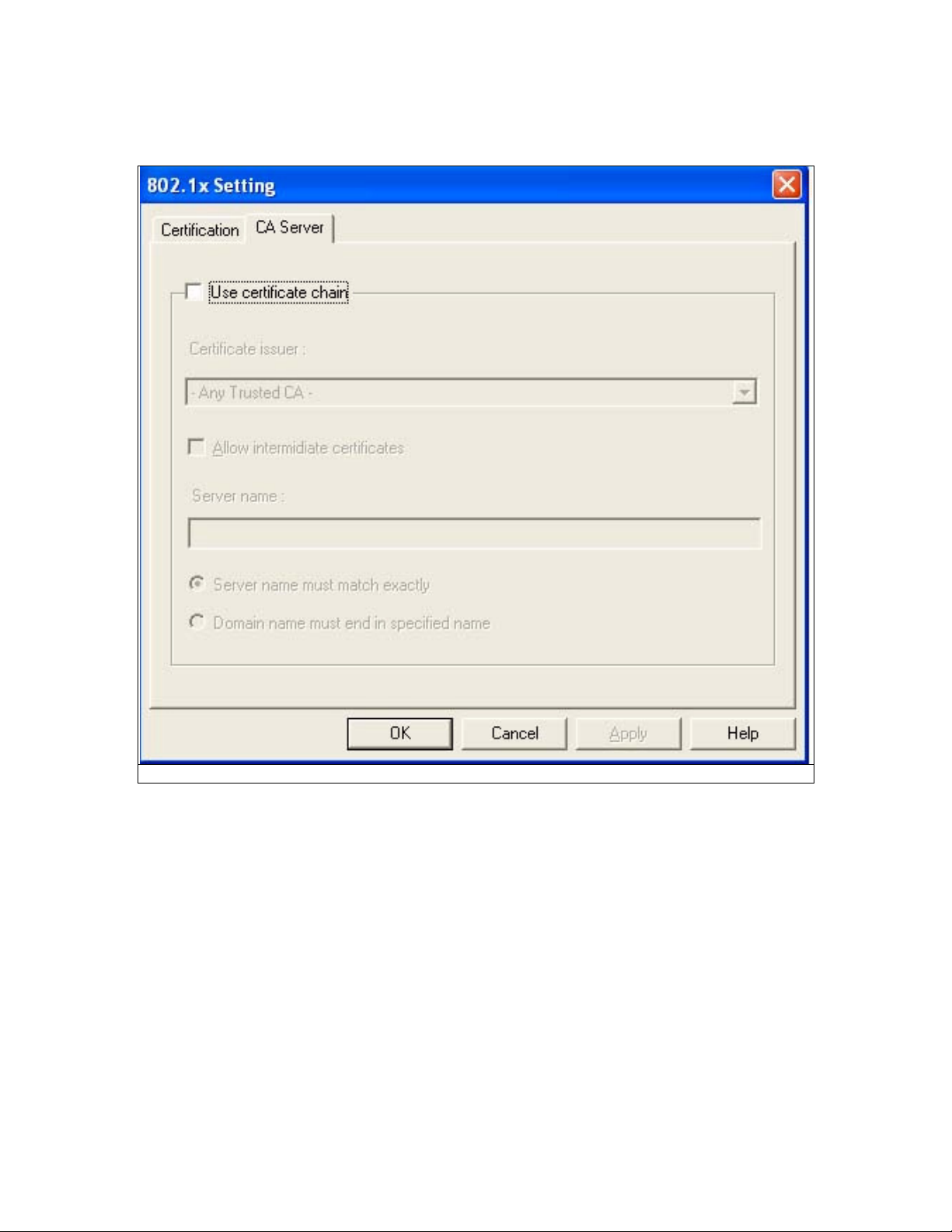
4. Fill out all the necessary information. If you want to use CA server, please click “CA Server”
tab. Please see Fig 5-11
Fig 5-11
5. Fill out all necessary information and click “OK” to save the profile.
Page 21
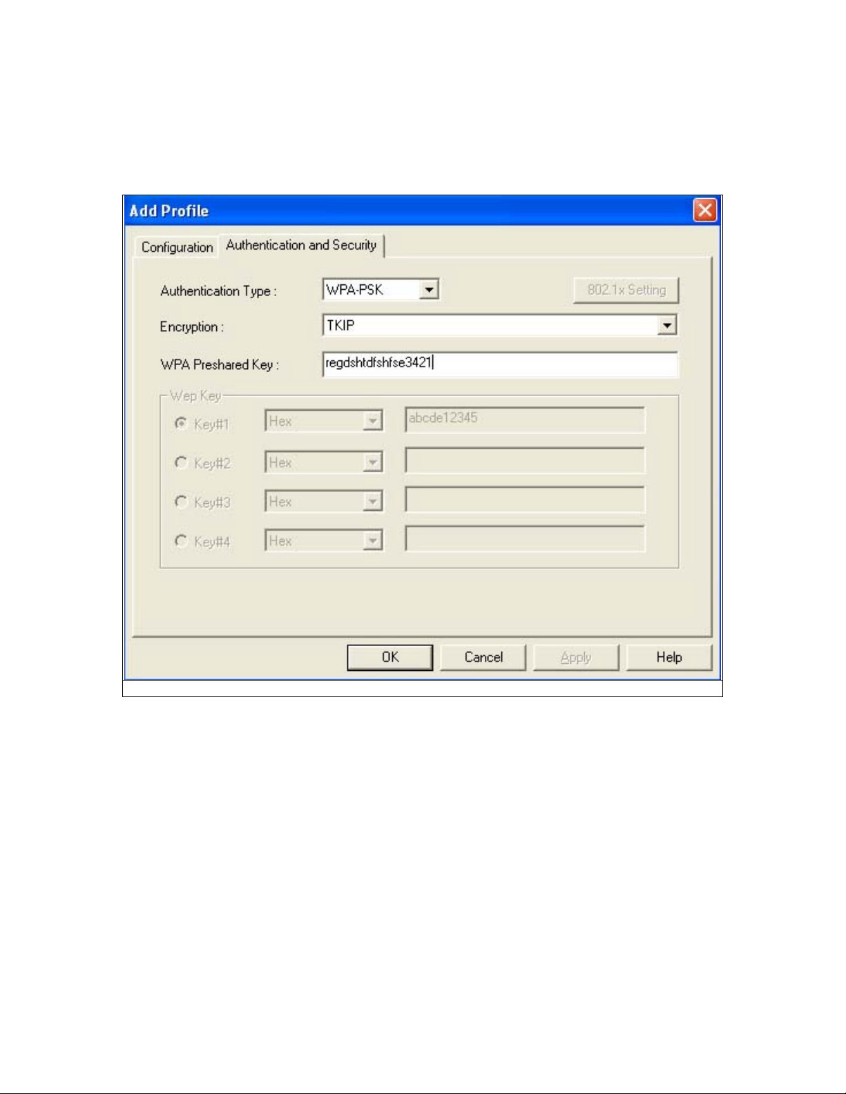
D. WPA-PSK
1. Select Authentication type: WPA-PSK
2. Select Encryption type: TKIP or AES
3. Enter the Key
4. Click “OK” to save the profile. Please see Fig 5-12
Fig 5-12
Page 22
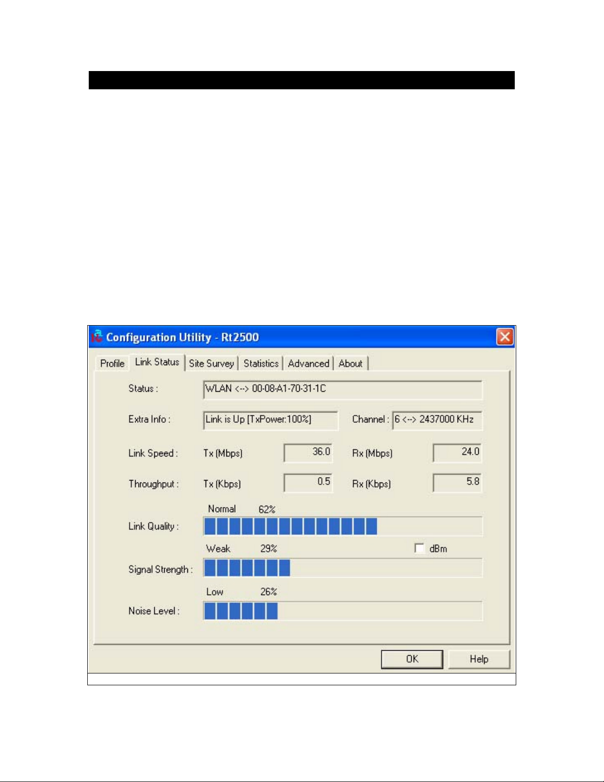
5.5 Link Status
The Link Status (Fig 5-13) provides the link information of the Wireless-G PCI Adapter.
When in Infrastructure Mode, Status will display the connection statistics for the network segment
that you are on.
The Channel field shows the channel which the wireless network devices are currently using.
The Link Speed: Tx(Mbps) field shows the transfer rate in megabits per second. Rx(Mbps) field
shows the receive rate in megabits per second.
The Throughput (Kbps) field is the amount of data moved successfully form one place to another
in a given time period.
The Link Quality field will display a bar indicating percentage, between 0 and 100 percent.
The Signal Strength field will display a bar indicating percentage, between 0 and 100 percent.
The Noise Level field will display a bar indicating percentage, between 0 and 100 percent.
Fig 5-13
Page 23
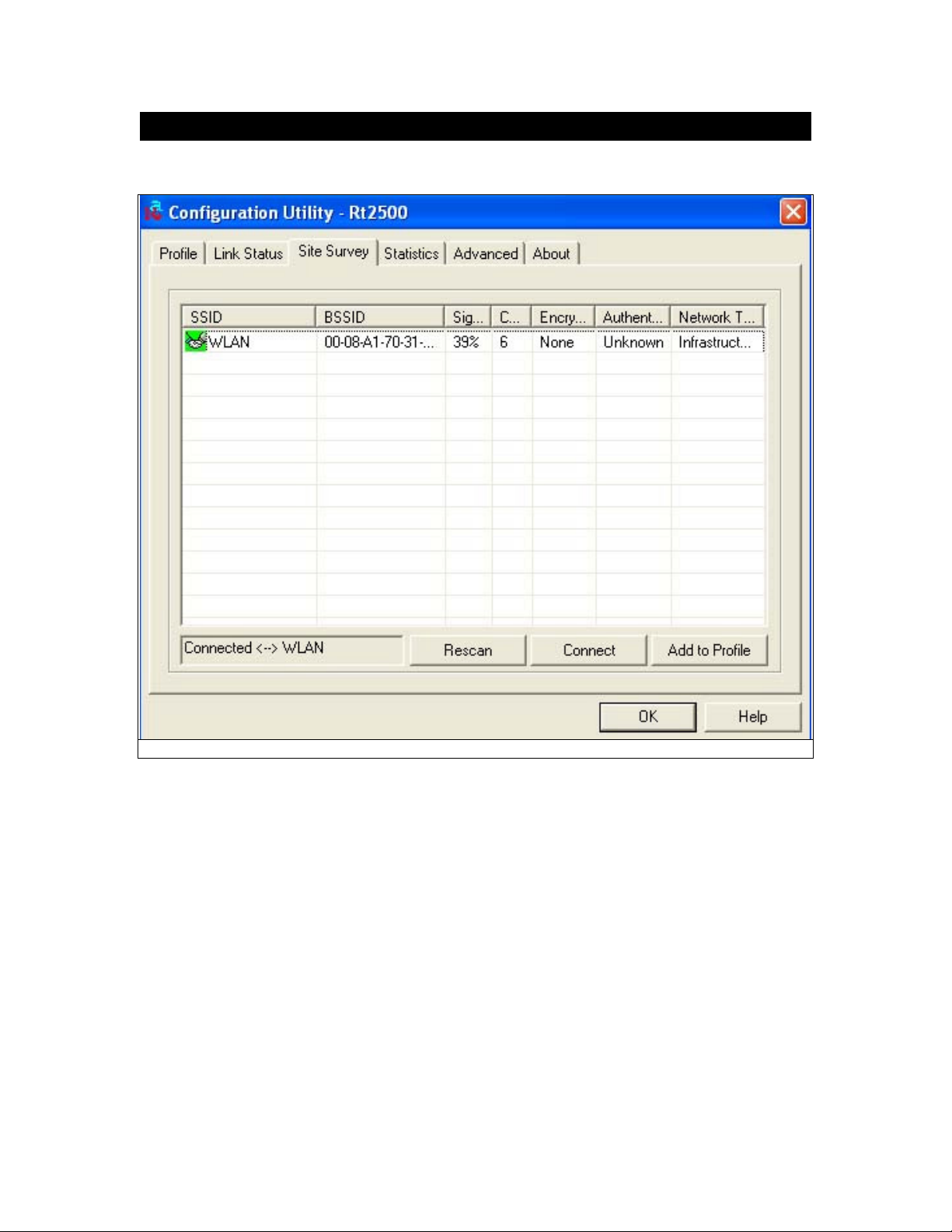
5.6 Site Survey
The site survey page displays a list of all Infrastructure and Ad-Hoc networks available for
connection. (Fig 5-14)
Fig 5-14
Information:
SSID – Service Set ID of the Wireless Network.
BSSID – Basic Service Set ID of the Wireless Network.
Signal – Signal Strength status.
Channel – The channel used by Wireless Network.
Encryption - Encryption type.
Authentication – Authentication type used.
Network Type - Wireless Network mode. (Infrastructure mode or Ad-Hoc mode)
Rescan - Click the Rescan button to re-search for wireless networks.
Connect – Select one of the networks on the list, and click the Connect button.
Add Profile – If you click this button, the Profile screen (Figure 5-6) will appear.
Page 24

5.7 Statistics
The Statistics screen (Shown in Fig 5-15) provides information about the Transmit Statistics and
Receive Statistics. You can reset counters if you need, otherwise click OK.
Fig 5-15
Page 25
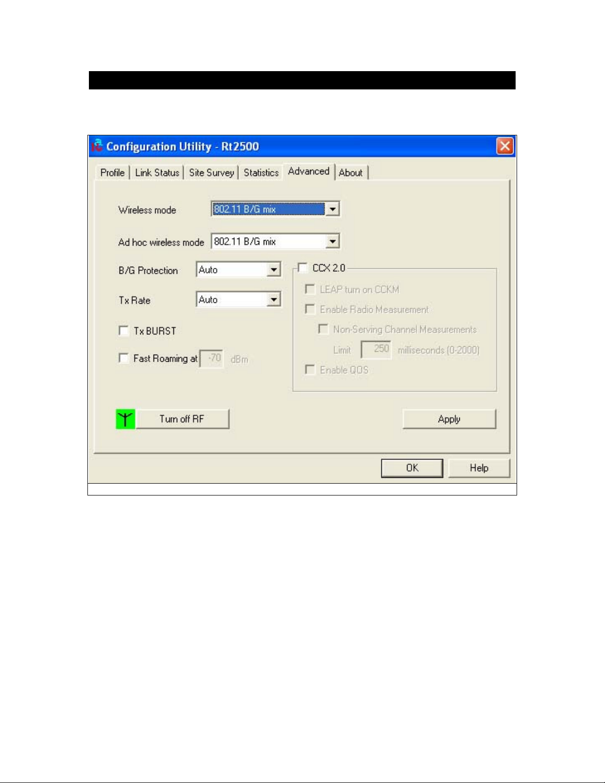
5.8 Advanced
The Advanced screen (Fig 5-16) shows settings for Wireless Mode, Ad hoc wireless mode, TX
BURST, B/G Protection, Tx Rate and RF On/Off.
Fig 5-16
Page 26

5.9 About
The About screen shows release dates as well as driver/utility versions and the MAC/IP address of
the card.
Fig 5-17
 Loading...