

Page 1
Page 2

PREFACE
Thank you for purchasing the 3.0 MP H.264/MPEG4/MJPEG Cube
Type WIFI Network Camera, a standalone system that can be
connected directly to an Ethernet, Fast Ethernet or Wireless
network. The elegant design makes it an ideal solution for offices,
shops and homes. Moreover, the camera are equipped with IR
LEDs and IR-cut filter, providing clear video in completely dark
environments.
The camera boasts high-definition video resolution, allowing for the
delivery of extremely detailed images and coverage 6 or more
times or larger than a VGA camera. To maximize the benefit of the
high-definition sensor, the camera employs several innovative
technologies for optimized bandwidth efficiency. The ROI function
enables users to quickly move to a target area for close-up shots
without moving the camera physically. Users can also receive only
the portions of the images they are interested in via the cropping
function. Furthermore, multiple video streams can be delivered
simultaneously in different resolutions, frame rates, and image
qualities for viewing on different platforms so as to meet different
needs or bandwidth constraints. The camera also offers activity
adaptive streaming support that dynamically allocates bandwidth
according to the video content and trigger state.
Moreover, the cameras boast 802.11b/g/n compatible wireless
connection, making installation easier and more cost-efficient. The
WPS function of camera makes wireless configuration easy and
straightforward. Together with the multi-lingual 32-channel
recording software, users can set up an easy-to-use IP
surveillance system with ease.
With other advanced features such as tamper detection, SD/SDHC
card onboard storage, and two-way audio, the camera is a fullfledged surveillance solution for indoor environments. The simple
installation procedures and web-based interface allow you to
- 1 -
Surveillance Solution
Page 3

integrate it into your network easily. With comprehensive
applications supported, the camera is your best solution for remote
monitor, high quality, and high performance video images.
This Advanced Installation Guide provides you with the instructions
and illustrations on how to use your camera, which includes:
Chapter 1 Introduction to Your Camera describes the features
of the camera. You will also know the components and
functions of the camera.
Chapter 2 Hardware Installation helps you install the camera
according to your application environment. You can
use this camera at home, at work, at any where you
want.
Chapter 3 Accessing the Camera lets you start using your
camera without problem. The camera can be set up
easily and work within your network environment
instantly.
Chapter 4 Configuring the Camera guides you through the
configuration of the camera using the Web browser on
your PC.
Chapter 5 Appendix provides the specification of the camera
and some useful information for using your camera.
NOTE The illustrations and configuration values in this guide are for
reference only. The actual settings depend on your practical
application of the camera.
- 2 -
Page 4

Contents
P
REFACE
C
HAPTER
I
NTRODUCTION TO YOUR CAMERA
1.1 C
1.2 G
1.3 F
1.4 S
C
HAPTER
W
IRELESSCONNECTION
2.1
2.2 A
C
HAPTER
A
CCESSING THE CAMERA
3.1 U
3.2 A
3.3 C
C
HAPTER
C
ONFIGURING THE CAMERA
4.1 U
4.2 S
4.3 N
4.4 A
4.5
4.6
4.7 I
Appendix ............................................................ 55
A.1 S
............................................................... 1
1............................................................. 4
............................... 4
HECKING THE PACKAGE CONTENTS
ETTING TO KNOW YOUR CAMERA
EATURES AND BENEFITS
YSTEM REQUIREMENT
....................................................6
.......................................................8
...................................4
......................................5
2 ............................................................. 9
............................................. 9
USING
WPS B
PPLICATIONS OF THE CAMERA
UTTON
..........................................................9
........................................ 10
3 ........................................................... 11
........................................ 11
SING
IPF
INDER
.............................................................. 11
CCESSING TO THE CAMERA
ONFIGURING THE IP ADDRESS OF THE
............................................ 12
PC ....................... 17
4 ........................................................... 18
..................................... 18
SING THE WEB CONFIGURATION
YSTEM
........................................................................... 19
ETWORK
UDIO/VIDEO/EXPOSURE/IMAGE/WDR
EVENT
STATUS
NTELLIGENT VIDEO ANALYSIS
PECIFICATION
........................................................................ 23
.............................................................................. 36
............................................................................ 45
................................................................ 55
..................................... 18
............................... 28
........................................... 44
- 3 -
Page 5

CHAPTER 1
Surveillance Solution
INTRODUCTION TO YOUR CAMERA
1.1 Checking the Package Contents
Check the items contained in the package carefully. You should
have the following:
One Network Camera
One AC Power Adapter
Accessory Package (Screws / Plastic Anchors)
□ One Installation CD-ROM (
□ One Quick Installation Guide(
NOTE Once any item contained is damaged or missing, contact the
authorized dealer of your locale.
optional
optional
- 4 -
)
)
Page 6
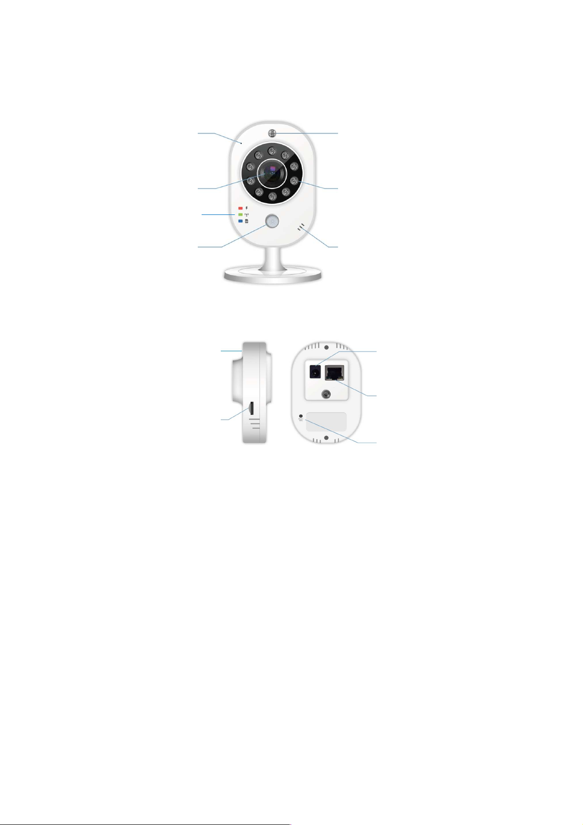
Power Input
Ethernet Port
WPS and Reset
Microphone
Lens
PIR
Sensor
Temperature and
IR LED and ICR
Speaker
802.11n Wi
-
Fi
Micro SD
Slot
Status LED
1.2 Getting to Know Your Camera
Front Panel
Humidity Sensors
Rear Panel
- 5 -
Page 7

1.3 Features and Benefits
H.264/MPEG4/MJPEG Multi-codec Supported
The camera provides you with excellent images by the
H.264/MPEG4/MJPEG multi-codec selectable technology,
allowing you to adjust image size and quality, and bit rate
according to the networking environment.
High Resolution Surveillance
Equipped with 3 Mega pixel color CMOS sensor, the high
performance camera is designed for your professional
surveillance and security applications. The image resolution
is up to 2048x1538 (3M).
Remote Control Supported
By using a standard Web browser or the bundled GVMS
software application, the administrator can easily change the
configuration of the camera via Intranet or Internet. In
addition, the camera can be upgraded remotely when a new
firmware is available. The users are also allowed to monitor
the image and take snapshots via the network.
Multiple Profiles Supported
The camera supports multiple profiles simultaneously, so
that you can separately set up different image settings (such
as image quality and frame rate) for the three video types of
the camera: H.264, MPEG4 and MJPEG.
Flexible Audio Capability
The camera allows you to connect the external microphone
to receive on-the-spot audio via the Internet, allowing you to
monitor the on-site voice. In addition, you can connect an
external active speaker to the camera to speak through the
camera (supporting mono audio only).
Supports RTSP
The camera supports RTSP (Real Time Streaming Protocol),
which is a technology that allows you to view streaming
- 6 -
Page 8

media via the network. You can view the real-time video with
the Quick Time player or RealPlayer. To view the real-time
streaming image on your computer, open the Web browser
and enter the RTSP link:
Stream 1: rtsp://(IP address of the camera)/stream1
Stream 2: rtsp://(IP address of the camera)/stream2
Stream 3: rtsp://(IP address of the camera)/3gp
Temperature and Humidity Sensor Supported
The camera provides the display of temperature and
humidity in real-time or send the user daily report. Alert the
user when temperature and humidity exceed or bellow
certain value.
Multiple Platforms Supported
The camera supports multiple network protocols, including
TCP/IP, SMTP e-mail, HTTP, and other Internet related
protocols. Therefore, you can use the camera in a mixed
operating system environment, such as Windows XP/ Vista,
and Windows 7.
Multiple Applications Supported
Through the remote access technology, you can use the
cameras to monitor various objects and places for your own
purposes. For example, babies at home, patients in the
hospital, offices and banks, and more. The camera can
capture both still images and video clips, so that you can
keep the archives and restore them at any time.
PIR Sensor Supported
The camera provides PIR (Passive Infrared) sensor for
human detection. The PIR sensor detects motion by
measuring changes in infrared light. The sensor can for
example be used in low-light environments where video
motion detection is not reliable.
- 7 -
Page 9

ONVIF Compliance
This product supports ONVIF. For more information, refer to
www.onvif.org.
1.4 System Requirement
Networking
LAN 10Base-T Ethernet or 100Base-TX Fast
Ethernet; Auto-MDIX.
Accessing the Camera using Web Browser
Platform Microsoft® Windows® XP/Vista/Win7
CPU Intel Core 2 Duo or higher
RAM 1GB or more
Resolution 1024x768 or higher
User Interface Microsoft® Internet Explorer 7.0 or
above; Apple Safari 2 or above; Mozilla
Firefox 2.00 or above; Google Chrome
Accessing the Camera using GVMS
Platform Microsoft® Windows® XP/Vista/Win7
Resolution 1024 x 768 or higher
Hardware Requirement:
1~8 cameras Intel Core 2 Duo 2GB RAM
9~32 cameras Intel Core 2 Quad 4GB RAM
NOTE If you connect multiple cameras to monitor various places
simultaneously, you are recommended to use a computer with higher
performance.
- 8 -
Page 10
CHAPTER 2
Surveillance Solution
WIRELESS CONNECTION
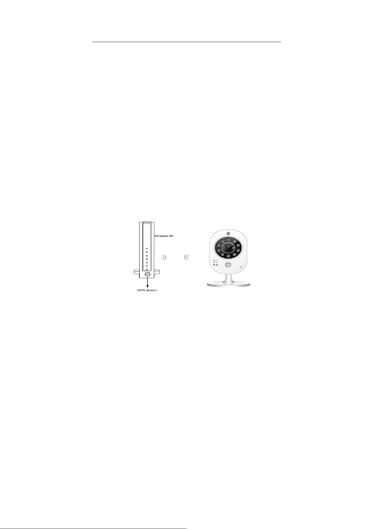
2.1 Using WPS Button
Make sure your AP (Access Point) and Operation System
support WPS (Access Protected Setup) functions WPS
enables easy setup with compatible Aps.
Disconnect your LAN cable, and wait for the LED to turn red.
Press the WPS button for 1 second.
Press and hold down the WPS button on your AP (some
router/AP will have a virtual button on their management
software instead). Refer to your AP's documentation for
details using its WPS functions.
When WPS configuration is done, wireless connectivity will be
established and the security encryption, such as WEP or WPAPSK, will be synchronized with the AP.
As for IP setting, the camera's use of DHCP or static IP is
determined by your configuration on the network camera via the
web based configuration of firmware. The camera's default is
DHCP.
- 9 -
Page 11
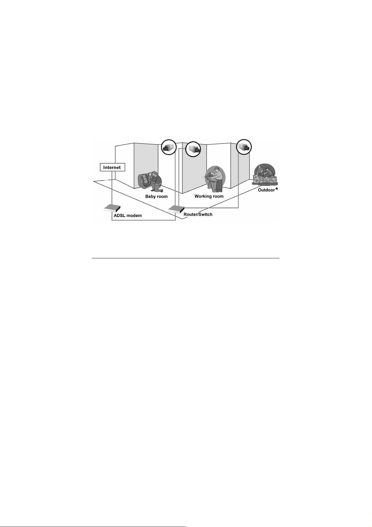
2.2 Applications of the Camera
The camera can be applied in multiple applications, including:
Monitor local and remote places and objects via Internet or
Intranet.
Capture still images and video clips remotely.
Upload images or send email messages with the still images
attached.
The following diagram explains one of the typical applications for
your camera and provides a basic example for installing the
camera.
Home Applications of the Internet Cameras
* Please have the camera enclosed by waterproof housing when using in outdoor.
- 10 -
Page 12
CHAPTER 3
Search
Surveillance Solution
ACCESSING THE CAMERA
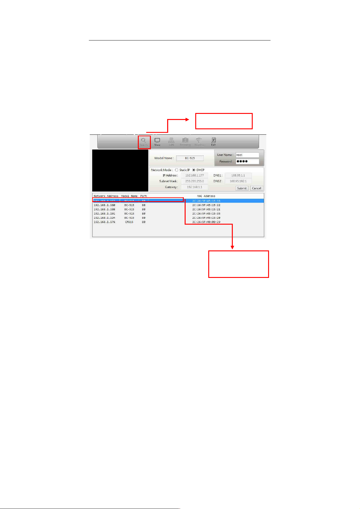
3.1 Using IP Search Software (CamWizard)
The camera comes with a conveniently utility, CamWizard, which
is allowing you to search the camera on your network easily.
1. Click the CamWizard item to launch the utility. The control
panel will appear as below.
- 11 -
Click
camera information.
to get the
Display the connected
camera(s).
Double click to link the
Camera.
Page 13
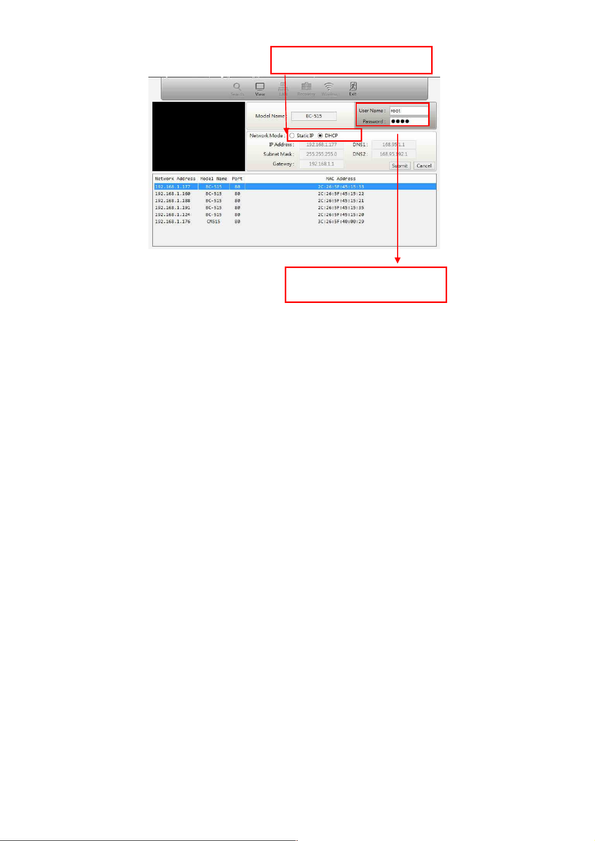
root
Click DHCP/Static IP to modify the IP
address of the selected camera.
Enter the default User name (
password (root) and press OK the IP
address will be change.
) and
2. Once you get the IP address of the camera, launch the Web
browser or GVMS to access your camera.
3.2 Accessing to the Camera
Whenever you want to access the camera:
1. Since the default configuration of the camera is DHCP mode
enabled, you are recommended to launch IPFinder to search
the IP address that is assigned to the camera by the DHCP
server, and then click Link to access the camera via the Web
browser.
- 12 -
Page 14
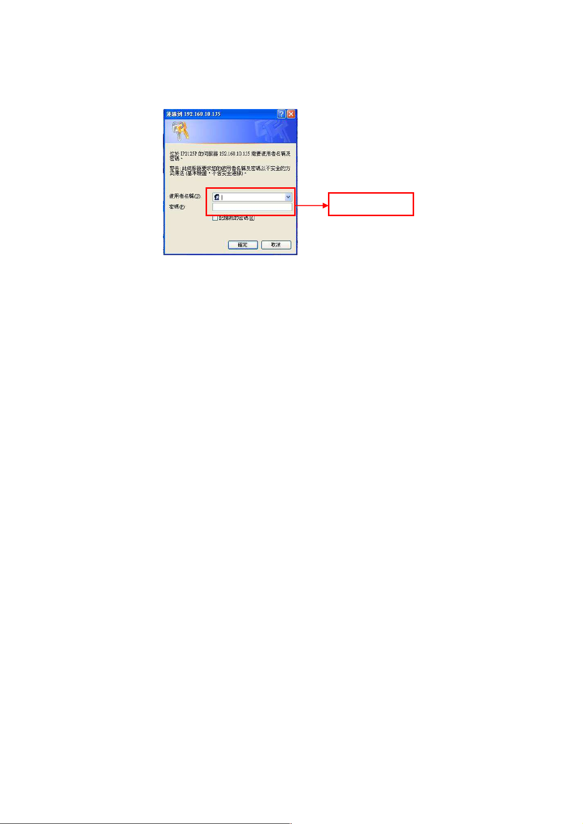
2. If Network Camera can't get IP Address under DHCP mode,
Enter the User name
and Password.
the default IP Address will be 192.168.1.99.
3. When the login window appears, enter the default User name
(root) and password (root) and press OK to access to the
main screen of the camera’s Web Configuration.
NOTE If you are initially access to the camera, you will be ask to install a
new plug-in for the camera. Permission request depends on the
Internet security settings of your computer. Click Yes to proceed.
After you login into the Web Configuration of the camera, the Main
screen will appear as below:
- 13 -
Page 15
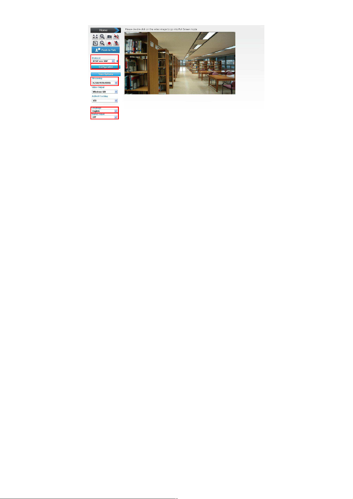
The Main screen of the Web Configuration provides you with many
useful information and functions, including:
Configuration: Click for configuring the camera settings.
Stream: The device supports multi-profile function for H.264,
MEPG4 and JPEG simultaneously. A user can
choose the proper and/or preferred profile which is
listed here.
Protocol: Select the protocol type: RTS, TCP, HTTP or RTSP
over HTTP.
Language: The device can provide multiple languages to meet
customer’s requirement.
Digital Output: Switch digital output interface on or off.
2-Way Audio The device supports 2-way audio function. A user
can choose to enable or disable this function by toggling the icon
below.
- 14 -
Page 16
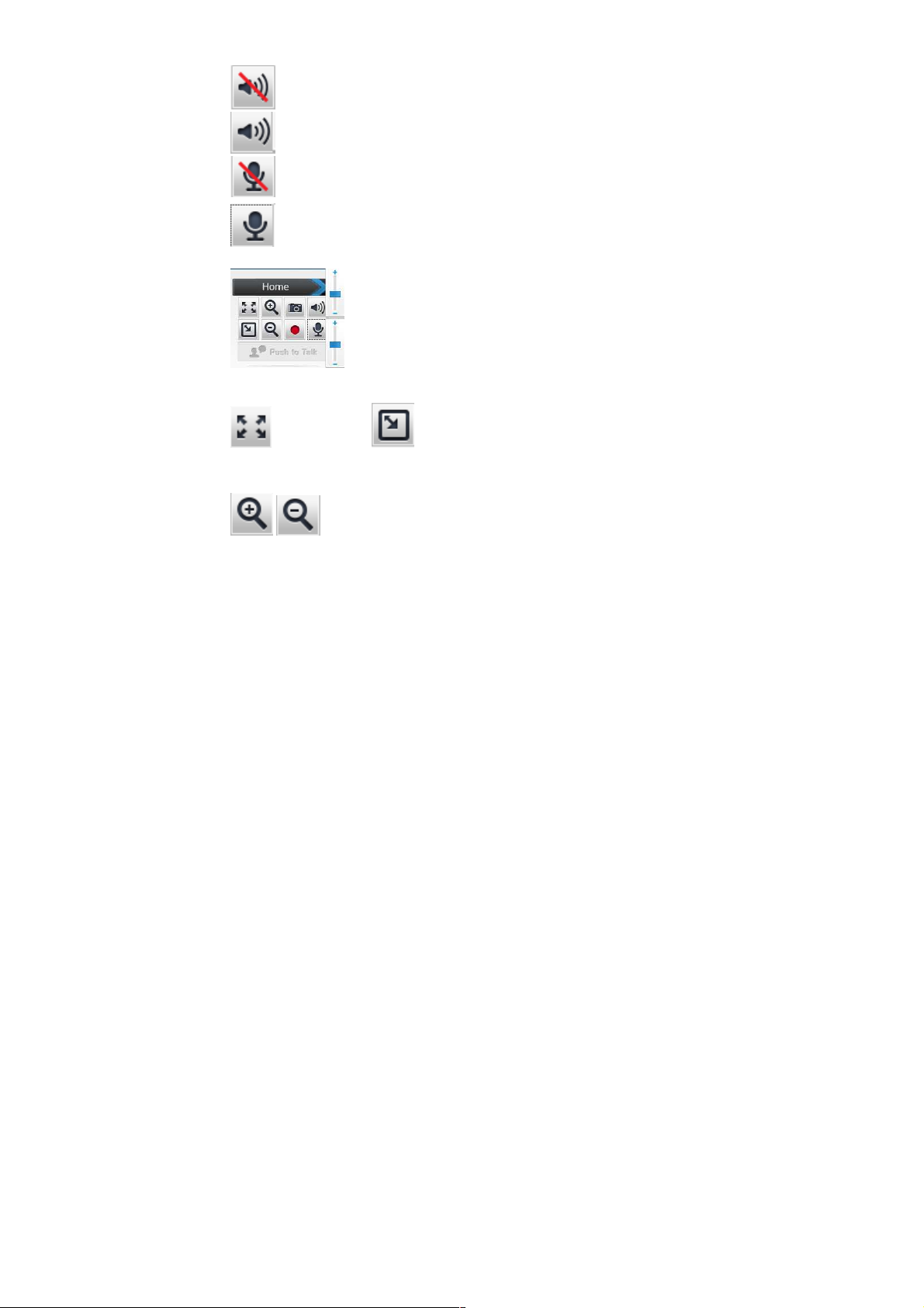
: Disable speaker function.
: Enable speaker function.
: Disable audio uploading function
: Enable audio uploading function.
Volume: Click Speaker button to activate this
function. Scroll the control bars to adjust the audio attribute.
Original size/
view between original size (full size: 3MegaPixels) and preview
size
(smaller size).
Digital Zoom: From 1X to 10X, so you can see
objects in video in detail.
Please note: that digital zoom uses computer algorithm to
enlarge the video and some details may lost. If you need
to focus on detail of specific objects in video view, please
use optical zoom ring on lens set of IP camera.
Preview Size: Switches live image
- 15 -
Page 17
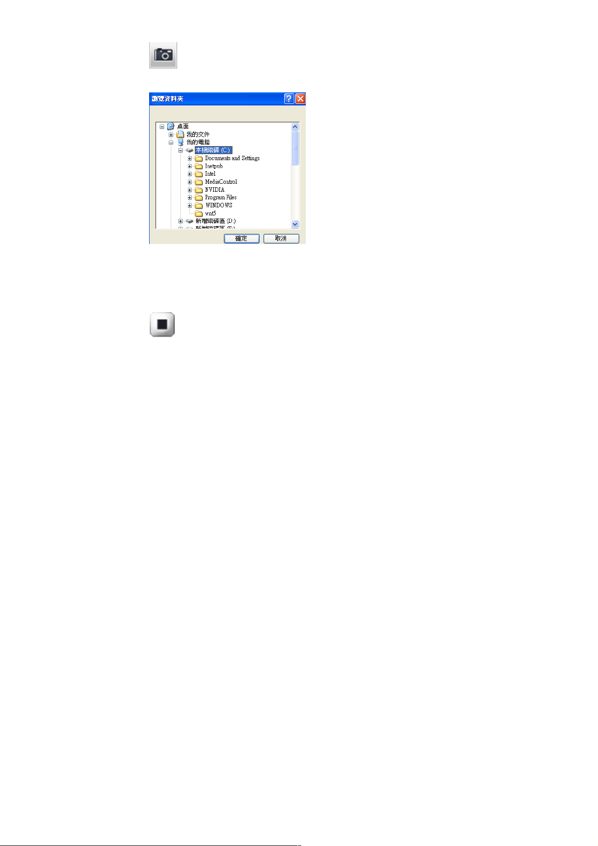
Snapshot: Take a snapshot or camera video
and save image file on your computer.
Click ‘Save’ button when you see the image you wish to save, and
you’ll be prompted to indicate the folder on your computer to save
image file.
If you changed your mind and don’t want to save image file, click
‘Cancel’.
button to start recording. The video file is saved as ASF format into
your local PC. While you want to stop it, press Stop to recording.
Record: Click Record to activate this function. Press Record
- 16 -
Page 18

3.3 Configuring the IP Address of the PC
If you are failed to access to the camera, please check the IP
address of your computer. When you connect the camera to your
computer directly to proceed with configuration of the camera, you
need to set up the IP addresses to be in the same segment for the
two devices to communicate.
1. On your computer, click Start > Control Panel to open the
Control Panel window.
2. Double-click Network Connection to open the Network
Connection window.
3. Right-click Local Area Connection and then click Properties
from the shortcut menu.
4. When the Local Area Connection Properties window appears,
select the General tab.
5. Select Internet Protocol [TCP/IP] and then click Properties to
bring up the Internet Protocol [TCP/IP] Properties window.
6. To configure a fixed IP address that is within the segment of
the camera, select the Use the following IP address option.
Then, enter an IP address into the empty field. The suggested
IP address is 192.168.1.x (x is 1~254 except 99), and the
suggested Subnet mask is 255.255.255.0.
7. When you are finished, click OK.
- 17 -
Page 19
CHAPTER 4
Surveillance Solution
CONFIGURING THE CAMERA
4.1 Using the Web Configuration
You can access and manage the camera through the Web browser
and the provided software application ZeroVew. This chapter
describes the Web Configuration, and guides you through the
configuration of the camera by using the Web browser.
To configure the camera, click “configuration “on the Main screen
of Web Configuration. The Web Configuration will start from the
Basic page.
The Web Configuration contains the settings that are required for
the camera in the left menu bar, including Network, Video, Audio
Event, Storage, System, Status, Video Analytics
- 18 -
Page 20
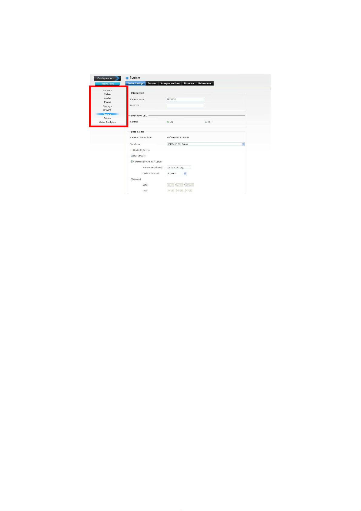
4.2 System
The System menu contains two sub-menus that provide the
system settings for the camera, such as the Camera Name,
Location, Date & Time, etc.
When completed, click Apply to save the settings.
4.2.1 System>>Device Settings
Information: This item allows you to assign the camera
name and location information.
- Camera Name: Enter a descriptive name for the camera,
which is helpful to identify the camera easily while multiple
cameras are connected within the network.
- Location: Enter a descriptive name for the location where
is monitored by the camera.
Indication LED: This item allows you to set the LED
illumination as desired. The available options include:
Normal and OFF.
- 19 -
Page 21

Date and Time: Enter the correct date and time for the system.
- TimeZone: Select the proper time zone for the region from
the pull-down menu.
- DayLight Saving: Select this option if the Daylight Saving
Time is used in your location.
Daylight Saving means a period from late spring to early
fall, and during the period many countries will set their
clocks ahead of normal local time by one hour to give more
daytime light in the evening.
- Don't Modify: Select this option to set the date and time
as system’s default settings.
- Synchronize with NTP Server: Select this option and the
time will be synchronized with the NTP Server. You need
to enter the NTP Server Address of the server and set the
Update Interval.
- Manual: Select this option to set the date and time
manually.
- Synchronize with PC: Select this option and the date &
time settings of the camera will be synchronized with the
connected computer.
4.2.2 System>>Firmware
Update Firmware: You can upgrade the firmware for your
camera once you obtained a latest version of firmware.
- Current Firmware Version: This item displays the current
firmware version.
- Update: Click Browse to locate the backup file on your PC
and then click Update.
4.2.3 System>>Maintenance
Factory Reset: Click Reset to restore all factory default
settings for the camera.
- 20 -
Page 22

Reboot: Click Reboot to restart the camera just like turning
the device off and on. The camera configuration will be
retained after rebooting.
Configuration: You can save your camera configuration as
a backup file on your computer. Whenever you want to
resume the original settings, you can restore them by
retrieving the backup file.
- Backup: Click the button to save the current configuration
of the camera.
- Restore: Click Browse to locate the backup file on your
PC and then click Restore. You can also click Restore
From SD CARD Device if the backup file is saved in the
inserted SD card.
4.2.4 System>> Account
Admin: To prevent unauthorized access to the camera’s
Web Configuration, you are strongly recommend to change
the default administrator password. Type the administrator
password twice and then click Modify to set and confirm the
password.
Users
- User Name/Password/Confirm Password: Enter the
user’s name you want to add to use the camera. Then,
enter the password twice for the new user. When done,
click Add to add the new user for the camera.
- User List: Display the existing users of the camera. To
delete a user, select the one you want to delete and click
Delete.
Guest
- User Name/Password/Confirm Password: Enter the
user’s name you want to add to use the camera. Then,
enter the password twice for the new user. When done,
click Add to add the new user for the camera.
- 21 -
Page 23

- UserList: Display the existing guests of the camera. To
delete a user, select the one you want to delete and click
Delete.
NOTE The “Users” can access the camera and control the Function
buttons of the camera’s Web Configuration; the “Guest’ can only view the
live view image from the Main screen of the Web Configuration while
accessing the camera. Only the “Admin” is allowed to configure the
camera through the Web Configuration.
4.2.5 System>>Management Ports
HTTPS: Select the Enable HTTPS option to enable HTTPS,
which is a secure protocol to provide authenticated and
encrypted communication within your network.
- HTTPS Port: Assign a HTTPS port in the text box. The
default HTTPS port is 443.
Warning!!!
The download firmware procedure cannot be interrupted. If the power
and/or network connection are broken during the download procedure, it
might possibly cause serious damage to the device. Strongly suggest that
DO NOT upgrade firmware via Wireless LAN due to high error rate
possibly and don't allow any other clients to access this unit during
updating procedure. Be aware that you should not turn off the power
during updating the firmware and wait for finish message. Furthermore, the
firmware upgrade procedure always is risk and do not try to upgrade new
firmware if it’s not necessary.
- 22 -
Page 24

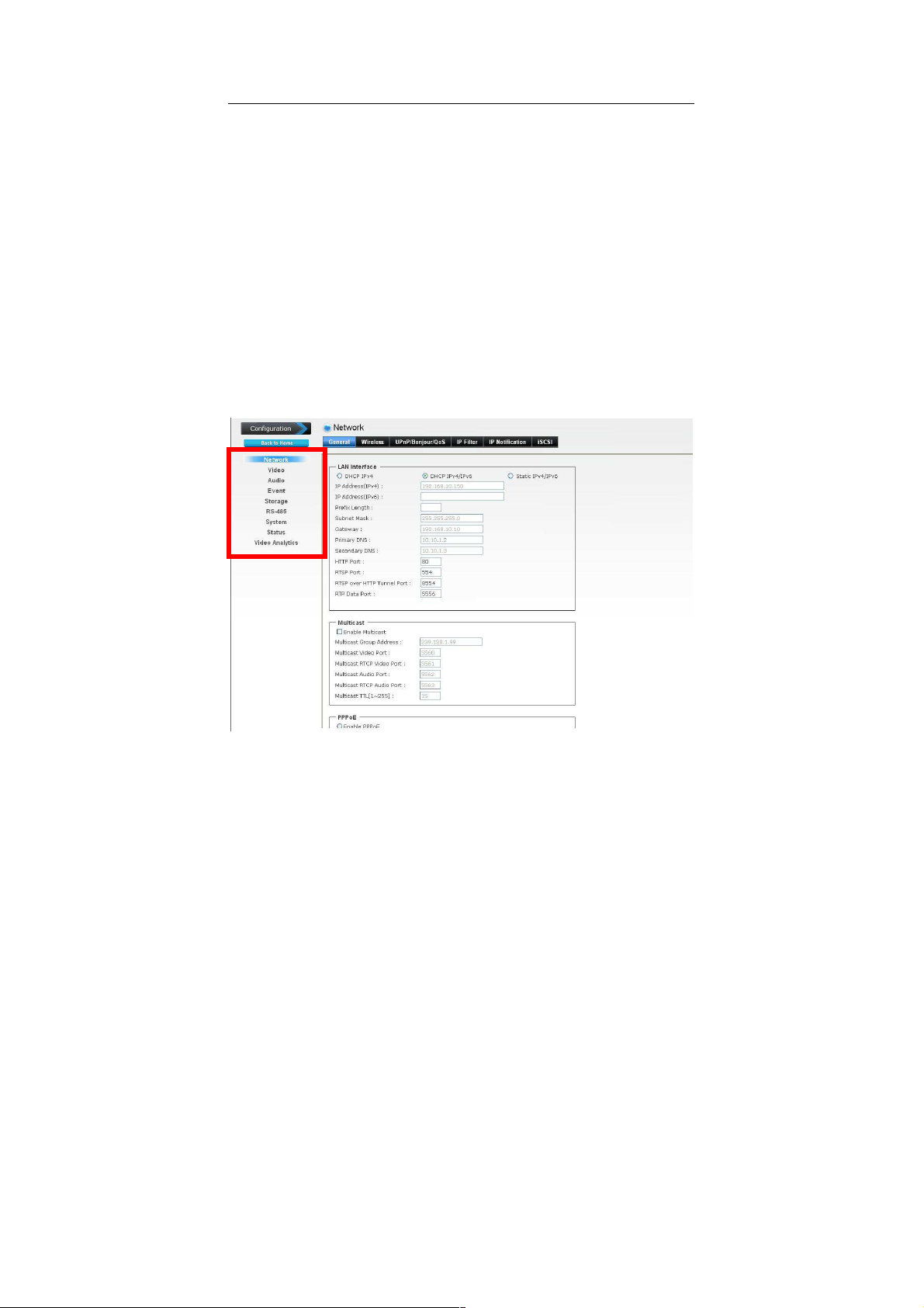
4.3 Network
The Network menu contains the networking related settings for the
camera, such as the IP Setting, DDNS Setting, IP Filter, etc.
When completed, click Apply to save the settings.
4.3.1 Network >> General
DHCP / Static IP: This field allows you to select the IP
address mode and set up the related configuration. The avail
options include: DHCP IPv4, DHCP IPv4/IPv6, and Static
IPv4/IPv6.
- DHCP IPv4: Select this option when your network uses the
DHCP server. When the camera starts up, it will be
assigned an IP address from the DHCP server
automatically.
- 23 -
Page 25

- DHCP IPv4/IPv6: DHCP for IPv6 enables the DHCP
server to pass the configuration parameters (e.g. the IPv6
network addressed) to the IPv6 nodes, which offers the
capability of automatic allocation of reusable network
addresses and additional configuration flexibility. Select
this option if your network supports DHCP IPv6 protocol.
When the camera starts up, it will be assigned an IP
address from the DHCP server automatically.
- Static IPv4/IPv6: Select this option to assign the IP
address for the camera directly. You can use IPFinder to
obtain the related setting values.
IP Address
(IPv4/IPv6)
Subnet Mask
Default
Gateway
Primary/
Secondary
DNS
HTTP Port The default HTTP port is 80.
RTSP Port
RTP Data Port
Enter the IP address of the camera. The
default setting is 192.168.1.99.
Enter the Subnet Mask of the camera. The
default setting is 255.255.255.0.
Enter the Default Gateway of the camera.
The default setting is 192.168.1.254.
DNS (Domain Name System) translates
domain names into IP addresses. Enter the
Primary DNS and Secondary DNS that are
provided by ISP.
The default RTSP Port (Real Time
Streaming Protocol) is 554.
RTP (Real-time Transport Protocol) is a data
transfer protocol defined to deliver live
media to the clients at the same time, which
defines the transmission of video and audio
files in real time for Internet applications.
The default RTP Data Port is 5556.
Enable Multicast: Select this option to enable the multicast
function of the camera, and then complete the following
settings so that you can deliver information from your camera
to a set of receivers.
- 24 -
Page 26

- Multicast Group Address: Assign a category of IP
addresses to receive the information from the camera.
- Multicast Video Port: Assign a multicast port for video in
the text box. The default port is 5560.
- Multicast RTCP Video Port: Assign a multicast port for
RTCP (real-time transport control protocol) video in the
text box. The default port is 5561.
- Multicast Audio Port: Assign a multicast port for audio in
the text box. The default port is 5562.
- Multicast RTCP Audio Port: Assign a multicast port for
RTCP (real-time transport control protocol) audio in the
text box. The default port is 5563.
- Multicast TTL: Set the value from 1 to 255. TTL (time to
live) is used to specify the time to live in the IP header so
that the system is able to decide whether or not the packet
has been in the network too long and should be discarded.
Enable PPPoE: Select this option when you use a direct
connection via the ADSL modem. You should have a PPPoE
account from your Internet service provider. Enter the User
Name and Password. The camera will get an IP address
from the ISP as starting up.
NOTE Once the camera get an IP address from the ISP as starting up,
it automatically sends a notification email to you. Therefore,
when you select PPPoE as your connecting type, you have to
set up the email or DDNS configuration in advance.
Enable DDNS: Select this option to enable DDNS service of
the camera. With the Dynamic DNS feature, you can assign
a fixed host and domain name to a dynamic Internet IP
address. To set up the DDNS, select the Provider from the
pull-down menu and then enter the required information in
the Host Name, User Name, and Password text boxes.
NOTE You have to sign up for DDNS service with the service provider
before configuring this feature.
- 25 -
Page 27

4.3.2 Network >> UPnP/Bonjour/Qos
UPnP: The camera supports UPnP (Universal Plug and
Play), which is a set of computer network protocols that
enable the device-to-device interoperability. Select the
Enable Discovery option to enable the feature.
In addition, it supports port auto mapping function so that
you can access the camera if it is behind an NAT router or
firewall. Select the Enable Port Mapping option to enable
the feature.
Bonjour: The devices with Bonjour will automatically
broadcast their own services and listen for services being
offered for the use of others. Select the Enable Discovery
option and, if your browser with Bonjour, you can find the
camera on your local network without knowing its IP address.
The Apple Safari is already with Bonjour. You can download
the complete Bonjour for Internet Explorer browser from
Apple's web site by visiting http://www.apple.com/bonjour/.
QoS: QoS (quality of service) is the ability to provide
different priority to different applications or data flows.
- Video DSCP: Assign the DSCP (DiffServ Code Point) of
the stream video from the camera by setting the value from
0 to 63.
- Audio DSCP: Assign the DSCP (DiffServ Code Point) of
the stream audio from the camera by setting the value
from 0 to 63.
4.3.3 Network >> IP Filter
The IP Filter setting allows the administrator of the camera to limit
the users within a certain range of IP addresses to access the
camera. Select the Enable Filter option and assign the range of IP
addresses that are allowed to access the camera in the Accept IP
Address field; or assign the range of IP addresses that are
blocked to access the camera in the Deny IP Address field.
- 26 -
Page 28

For example, when you enter 192.168.1.50/192.168.1.80 in
Start/End IP Address of Accept IP Address and then click Add,
the user whose IP address located within 192.168.1.50 ~
192.168.1.80 will be allowed to access the camera. On the other
hand, if you enter the IP range in Start/End IP Address of Deny
IP Address and then click Add, the user whose IP address located
within the range will not be allowed to access the camera.
To remove the assigned range of IP addresses for IP Filter, select
the setting in the Accept/Deny IP List and then click Delete.
4.3.4 Network >> IP Notification
In case the IP address is changed, system is able to send out an
email to alert someone if the function is enabled.
SMTP Notification (e-mail): If enable this function, then the “Send
to“ and “Subject” fields need to be filled.
Send To: Type the receiver’s e-mail address. This address is used
for reply mail.
Subject: Type the subject/title of the E-mail.
TCP Notification: If enable this function, then the “TCP Server“,
“TCP Port”, and “Message” fields need to be filled.
TCP Server: Type the server name or the IP address of the TCP
server.
TCP Port: Set port number of TCP server.
Message: The message will be sent to FTP server.
HTTP Notification: If enable this function, then the fields below
need to be filled.
- 27 -
Page 29

URL: Type the server name or the IP address of the HTTP server.
HTTP Login name: Type the user name for the HTTP server.
HTTP Login Password: Type the password for the HTTP server.
4.4 Video
The Audio/Video/Image menu contains three sub-menus to provide
the video and audio settings for the camera.
When completed, click Apply to save the settings.
- 28 -
Page 30

4.4.1 Video >> Video
High Resolution: Select this option to enable the camera to
capture images in high resolution mode (up to 2048X1536 @
25 fps). When the option is selected, you can select the
desired option from the Main Stream pull-down menu and
then complete the following to set the camera to capture
images in H.264, MPEG4, or MJEPG format.
- Computer View: Select the desired resolution that you
can view on PC from the Video Resolution pull-down
menu: 2048x1536 (QXGA), 1920x1080 (1080P),
1280x1024 (SXGA) or 1280x720 (720P).
You also need to select a proper setting of Frame Rate.
Please note that higher settings in Computer View and
Frame Rage obtain better video quality while it uses more
resource within your network.
NOTE When High Resolution is disabled, you can only set the
Video Resolution as 1280x720 (720P), 720x480 (D1),
640x480 (VGA), 320x240 (QVGA), or 176x144 (QCIF).
- Rate Control: Set the proper image quality by selecting
Video Quality or Bitrate, and then select the desired
settings from the pull-down menu:
Video Quality: Select Very Low, Low, Normal, High, or
Very High from the pull-down menu.
Bitrate: Set a proper value (in kbps) depending on your
network status.
- Mobile View (Not supported by MPEG4): The camera
supports 3GPP specification. Select the Disable option to
disable this feature. Otherwise, select 3GPP Without
Audio or 3GPP With Audio to transfer the video clips
without or with audio.
If you use a mobile phone that supports 3GPP, you can
also view the real-time streaming image captured by the
camera on your phone (with the default player on the
- 29 -
Page 31

phone) by entering the RTSP link:
rtsp://(IP address of the camera)/3gp
NOTE Your mobile phone and the service provider must support
3GPP function. Please contact your service provider when
you are failed to use this service.
4.4.2 Video >> Exposure
IR-CUT :The camera can automatically or manually
remove the IR-cut filter to let IR light into the sensor during
low light conditions.
- Auto mode:
The camera automatically removes the filter.
- Manual
User can use this function to determine the threshold , and
the camera switches between day mode and night mode
based on this specified threshold.
-Always ON
The camera switches on the IR cut filter at all times to block
infrared light.
- Always OFF
The camera switches off the IR cut filter at all times for the
sensor to accept infrared light.
-Schedule mode
- 30 -
Page 32

The camera switches between day mode and night mode
based on a specified schedule. Enter the start and end
time for day mode.
4.4.3 Video >> Audio
Enable Microphone: Select the option to enable the
camera’s audio in function, so that you can receive the onsite sound and voice from the camera.
Enable Speaker: Select the option to enable the camera’s
audio out function, so that the connected speaker can play
the sound and voice through the camera.
4.4.4 Video >> Image
Brightness: Adjust the brightness level from 0~255.
Contrast: Adjust the contrast level from 0~255.
Saturation: Adjust the colors level from 0~255.
Sharpness: Adjust the sharpness level from 0 ~ 100.
TIP Click Default to restore the default settings of the three options
above.
Mirror: Select Vertical to mirror the image vertically, or
select Horizontal to mirror the image horizontally.
Power Line Frequency: Select the proper frequency
according to the camera’s location to reduce the flicker:
NTSC/60Hz or PAL/50Hz.
Auto Iris: When you attach a DC-Iris lens with the auto Iris
function, select ON/OFF to enable/disable the feature.
Overlay Setting: This option is used to set the image
overlay and mask feature of the camera.
- Enable Time Stamp: Select this option to display the date
& time information on the live view image.
- 31 -
Page 33

- Enable Text Display: Select this option and enter your
heading text in the box to display the text information on
the live view image. You can set the displayed text in
transparent mode by selecting the Transparent option.
- Enable Image Overlay: Select Default Logo or User
Define Image to display the image overlay on the live view
image.
You can set the displayed image in transparent mode by
selecting the Transparent option and select the
background color as white or black.
When you select User Define Image, you can click
Browse to select the image file from your computer and
then click Update to apply the setting.
NOTE The width and height of the input overlay graphic should
be multiple of 4 at a maximum size of 160x128, and in
JPG or BMP (24-bit RGB) format.
4.4.5 Video >> ROI
ROI means Region of Interest. When the main stream is
set to High Resolution, user can select specified region for
monitoring, for this will saving the bandwidth if there are too many
collision on the network.
4.4.6 Video >> Advance
- 32 -
Page 34

Digital noise
reduction
A digital filter designed to reduce visible noise for Improving
visibility of images.
Fog compensation
Improved visibility of images in fog or smoke using Fog
compensation function
- 33 -
Page 35

4.4.7 Video >> Video Stabilization
Video Stabilization
is a video enhancement technique which
reduces the jitter in video caused due to camera shake. It is
achieved by moving a sub-frame in the video frame in
opposite direction to the camera movement
- 34 -
Page 36

4.4.8 Video >> Privacy Masks
Click Privacy Mask to open the settings page. On this page, user
can block out sensitive zones to address privacy concerns.
can use the mouse cursor to size and drag-drop the window, which
is recommended to be at least twice the size of the object (height
and width) you want to cover. Up to 4 privacy mask windows can
be set up on the same screen.
- 35 -
User
Page 37

4.5 Event
The Advance menu contains five sub-menus that allow you to set
up the advanced feature of the camera, including the event, event
schedule, motion detection, recording, RS-485, etc.
When completed, click Apply to save the settings.
- 36 -
Page 38

4.5.1 Event >> Event
Media Format: Select One Snapshot to send the alert
message with one still image captured by the camera, or
select H264 Video to send the alert message with one video
clip recorded by the camera.
You can set the attachment that is captured in Pre Event or
Post Event time when the event has been triggered.
FTP Event Server: Select Enable to enable the FTP server
for the camera.
-FTP Server: Enter the IP address of the target FTP server.
- Port: Enter the port number used for the FTP server.
- User Name: Enter the user name to login into the FTP
server.
- Password: Enter the password to login into the FTP server
- 37 -
Page 39

NOTE Due to the network environment, the camera may not upload
number of images that you set.
SMTP Event Server: Select Enable to enable the SMTP
server for the camera.
- SMTP Mail Server: Enter the mail server address.
For example, mymail.com.
- Port: Assign the SMTP port in the text box. The default
SMTP port is 25.
- Sender Email Address: Enter the email address of the
user who will send the email.
For example, gta@mymail.com.
- Receiver #1/#2 Email Address: Enter the first/second
email address of the user who will receive the email.
- Subject: Enter the subject of the message for the event.
- Authentication: Select the option according to the mail
server configuration.
- User Name: Enter the user name to login the mail server.
- Password: Enter the password to login the mail server.
- Test SMTP: When done, click the button to test the SMTP
server.
- SSL Encryption: If the mail server requires an encrypted
connection, you should select the SSL option.
NOTE Due to the network environment, the camera may not upload
number of images that you set.
Samba Event Server: Select Enable to enable the Network
Storage server for the camera.
- Samba Server Address: Enter the IP address of the
Network Storage server.
- Path: Assign the path for uploading the files on the
Network Storage server. For example, /Test/.
- User Name: Enter the user name to login into the Network
Storage server.
- 38 -
Page 40

- Password: Enter the password to login into the Network
Storage server.
- Test SMB: When done, click the button to test the network
storage server.
NOTE The recorded video files in Network Storage are enclosed by
MP4/AVI format without audio.
4.5.2 Event >> Event Schedule
Follow the steps below to set up the Event Schedule for the
camera:
1. Select Enable and enter the Event Name.
2. Select the Trigger by: Motion Detection, Digital Input 1, or
Digital Input 2 ,
3. Select the Action when triggered:
- Enable FTP: The camera will upload the attachment to
FTP when triggered.
- Enable EMAIL: The camera will send the attachment to
the assigned receiver when triggered.
- Enable Samba: The camera will transfer the attachment to
the network storage when triggered.
NOTE To enable the FTP/Email/Samba services, the required
- GO Preset: The camera will move to the preset position
when triggered. Please note that the function is available
only when a RS-485 device, such as an external camera
stand with rotation function, is connected to the camera.
- Enable SD CARD: The camera will store the attachment
to the SD card when triggered.
periodically time and etc
settings of must be completed in the Advance >> Event
section.
- 39 -
Page 41

- Trigger digital output: The camera will trigger the
connected device on the camera’s output for 1~60
seconds (according to the setting of the pull-down menu).
4. When done, click Add. The event profile will be added to the
Event list.
TIP To change/remove the event profile, select the desired profile from
the Event list and then click Modify/Delete.
- 40 -
Page 42

4.6 Status
The Status menu provides the current status of the camera,
including the basic information, audio/video settings, networking
configuration, and system logs. This information is very useful
when you need to repair or fix the problem of this IP camera.
4.6.1 Status>>Basic
4.6.2 Status>> audio/video
The examples of
pages
look like below:
basic, audio/video, and network
- 41 -
Page 43

4.6.3 Status>>Network
- 42 -
Page 44

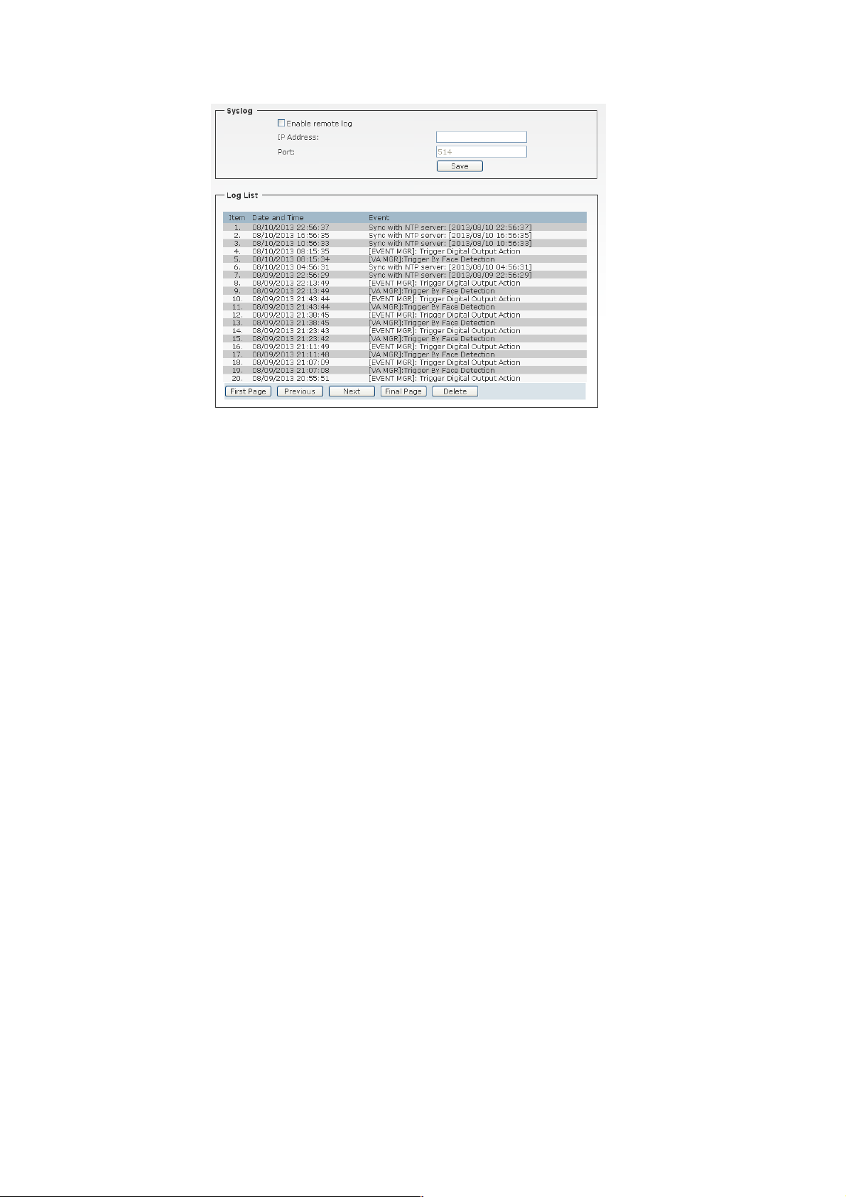
4.6.4 Status>>System Log
4.6.4.1 Remote Log
You can configure the Network Camera to send the system log file
to a remote server as a log backup.
Before utilizing this feature, it is suggested that the user install a
log-recording tool to receive system log messages from the
Network Camera. An example is Kiwi Syslog Daemon Visit
http://www.kiwisyslog.com/kiwi-syslog-daemon-overview/.
Follow the steps below to set up the remote log:
1. In the IP address text box, enter the IP address of the remote
server.
2. In the port text box, enter the port number of the remote server.
3. When completed, select Enable remote log and click Save to
enable the setting.
4.6.4.2 Log List
You can check the usage log of IP camera here. In this page, you
can click:
1. First page / Final page: Jump to first / final page of log.
2. Previous / Next: Jump to previous or next page of log.
3. Remove: Clear log.
- 43 -
Page 45
You’ll be prompted for confirmation.
4.7 Intelligent Video Analysis
The Intelligent Video Analysis option provides a suite of five video
analytics applications: Camera Tamper Detection (CTD), Intelligent
Motion Detection (IMD), Trip Zone (TZ), Object Counting (OC), and
Face Detection/Recognition (FD). Both processors can deliver
continuous CTD concurrently with one of the four remaining video
analytic functions, e.g. CTD plus IMD running simultaneously.
- 44 -
Page 46

Face Detection: Detects faces from the camera’s video input.
-Set whether or not to Enable Face Detection.
-Select Sensitivity to set the sensitivity level. As the
sensitivity grows, face detection becomes more close and
detailed.
-Select Direction to set directions for detection: up, left, and
right. The system supports to detect faces with face
inclination +/- 45°, face direction +/- 30° in vertical direction
and +/- 60° in horizontal direction.
- Set whether to use Detection result overlay. When faces
are detected, their positions and sizes are marked with
rectangles on the screen.
-Set whether or not to Enable the calibration mask with
minimum face size of 20x20 pixels
TIP
The Face Enhancement function improves the visibility of
human face images, making it easier to see and identify in
more natural conditions when monitoring and recording.
- 45 -
Page 47

Face Recognition: Recognize faces from the camera’s pre-
loaded database of faces.
-Set whether or not to Enable Face Recognition.
-Select Confidence Level to set the confidence threshold.
Threshold for the input face confidence when compared to
the faces in the database.
- Set whether to use Face Register. It supports run-time
addition and deletion of registered faces in the database.
Camera Tamper Detection
Camera Tamper Detection (CTD) detects tampering events in
surveillance cameras that may compromise the integrity of the
video content. Examples of camera tampering include obstructing
the lens with paint or a foreign object, adjusting the lens' focus or
aperture settings, pointing the camera in a different direction, and
- 46 -
Page 48

turning off the lights (if indoors with no major change in ambient
illumination expected). CTD can tolerate the effects of automatic
camera gain, camera shaking that causes mild image jitter (less
than +/- 4 pixels in any direction), and dimly lit scenes.
- Set whether or not to Enable Camera Tamper Detection
- Select Sensitivity to set the sensitivity level.
The higher the sensitivity, detects the minutest tampering attempts.
- Select Reset Time. Once a tampering is detected, the camera will
resume a normal operating after a certain stability time (Reset
Time) during which no detection will be performed.
- Select Alarm Type to specify the activation condition.
Intelligent Motion Detection
Detect the moving objects within user-defined zones in the
camera’s field of view. This analytics event is triggered when
a moving object in a user-defined zone is detected. Up to four
zones can be defined within the camera’s field of view.
- 47 -
Page 49

Objects must be moving and visible within the boundary of a
zone for at least 100 ms. Minimum and maximum dimensions
supplied by the user serve as guidance to internal
segmentation algorithms but do not strictly disqualify objects
from consideration. Motion in any direction inside a zone will
trigger an event.
-Set whether or not to Enable Intelligent Motion Detection
- Select Sensitivity to set the sensitivity level. A high sensitivity
setting makes it less likely that an event is missed,
but can make the algorithm susceptible to false
alarms.
- Select Calibration (People or Vehicle Object Sizes). The
minimum and maximum bounding box size of objects
can be specified to improve detection accuracy.
People or Vehicle Minimum Size: minimum expected width
and height of an object in the scene. Width and height values
must be at least 6 pixels. If small objects cause unwanted
- 48 -
Page 50

false detections, consider increasing the minimum dimensions.
People or Vehicle Maximum Size: maximum expected width
and height of a person in the scene. Width and height
maximum dimensions should be larger than their
corresponding minimum dimensions, and should not exceed
more than half the frame size.
- Select Zones Settings to specify the multiple activation zones.
Up to four independent zones, where each zone is a userdefined polygon with a maximum of 16 nodes. Each node
defined by fixed-point coordinate pair lying within image
boundaries. The first and last nodes should be identical. An
object’s size must satisfy the minimum area defined by the size
criterion (above) to be detected. The zone ID is reported along
with the event.
Trip Zone
Detects objects moving from one user-defined zone to
another; can also be used for “wrong way” detection. A Trip
Zone event occurs when an object(s) is detected moving
across the common edge shared by exactly two adjacent
zones. The zones are defined as two polygonal regions that
- 49 -
Page 51

share exactly one common edge. An object crossing this
edge must appear in each zone for at least 0.5 seconds to be
detected6. To satisfy the 0.5 second requirement, the size
and shape of each zone should be large enough to
accommodate the size and velocity of all targeted objects.
-Zone 1: User defined polygon with a maximum of 16 nodes.
Each node defined by fixed-point coordinate pair lying within
image boundaries. Must be defined before Zone 2. The first
and last nodes should be identical.
-Zone 2: User defined polygon with a maximum of 16 nodes.
Each node defined by fixed-point coordinate pair lying within
image boundaries. Must be defined after Zone 1. The first and
last nodes should be identical.
-Directionality:
Zone 1 to Zone 2: Event detected only if object moves from
zone 1 to zone 2.
- 50 -
Page 52

Zone 2 to Zone 1: Event detected only if object moves from
zone 2 to zone 1.
Bi-directional: Event detected if object moves either from
zone 1 to 2 or from zone 2 to 1.
-Sensitivity:
A high sensitivity setting makes it less likely that an event is
missed, but can make the algorithm susceptible to false
alarms.
-Object Sizes:
People Minimum Size – minimum expected width and
height of a person in the scene. Width and height values
must be greater than 16 pixels.
People Maximum Size – maximum expected width and
height of a person in the scene. Object width must be less
than 80 pixels and height must be less than 48 pixels.
Vehicle Minimum Size – minimum expected width and
height of a vehicle in the scene. Width and height values
must be greater than 16 pixels.
Vehicle Maximum Size – maximum expected width and
- 51 -
Page 53

height of a vehicle in the scene. Object width must be less
than 80 pixels and height must be less than 48 pixels.
Object Counting: Count the number of objects moving
through the camera’s field of view (from top-to-bottom or from
left-to-right). An Object Counting event occurs when an
object is detected moving from one half of the image to the
other half. This application provides an estimate of the
number of objects that trigger the event. Each half of the
image is designated as either zone 1 or zone 2. The objects
must appear in each image zone for at least 0.5 seconds.
- Counter Orientation:
Top-Bottom: Event detected when objects move across top
and bottom halves of the image.
Left-Right: Event detected when objects move across left
and right halves of the image.
- 52 -
Page 54

- Directionality:
Zone 1 to Zone 2: Event detected only if object moves
from zone 1 to zone 2
Zone 2 to Zone 1: Event detected only if object moves from
zone 2 to zone 1
Bi-directional: Event detected if object moves either from
zone 1 to 2 or from zone 2 to 1
- Sensitivity:
A high sensitivity setting makes it less likely that an event
is missed, but can make the algorithm susceptible to false
alarms.
- Object Sizes:
Expected width and height of an object in the scene. Width
and height values must be greater than 16 pixels, and
smaller than 64 pixels.
- 53 -
Page 55

- 54 -
Page 56

Appendix
Surveillance Solution
A.1 Specification
Image Sensor
Sensor 1/3” 3 Megapixel color CMOS Sensor
Resolution 2048 x 1536
Min. Illumination 0.1 Lux
Lens Assembly
Lens Type Board Type
View Angle 80 degree
Auto Iris Fixed-Iris
Night Vision Built-in removable IR cut filter
System Hardware
Network Processor DSP base
RAM 128MB DDR SDRAM
ROM 128MB NAND Flash
Power DC 5V / 1A
Power Consumption 4W max.
Video
Compression H.264/MPEG4/MJPEG
Video resolution QXGA (2048x1536) @ 25fps;
1080P (1920x1080) @ 30fps;
Communication
SXGA (1280x1024) @ 30fps;
720p (1280x720) @ 30fps;
VGA (640x480) @ 30 fps;
QVGA (320x240) @ 30 fps;
QCIF (176x144) @ 30 fps
- 55 -
Page 57

LAN 10/100Mbps Fast Ethernet with Auto-
MDIX
Wireless IEEE802.11n
Protocol support TCP/IP, IPV6, UDP, ICMP, DHCP, NTP,
DNS, DDNS, SMTP, FTP, HTTP,
HTTPs, Samba, PPPoE, UPnP, Bonjour,
RTP, RTSP, RTCP, ONVIF Profile S,
ISCSI
Audio
Input Build-in Microphone
Output Build-in Speaker
Codec G.711/AMR (AMR is for 3GPP only)
User Interface
LAN One RJ-45 port
SD Card One SD/SDHC card slot
Reset/WPS One reset/wps button
LEDs Power LED (amber); Link LED (green),
SD Card Status (Blue)
Software
OS Support Windows XP/Vista, and Windows 7
Browser Internet Explorer 7.0 or above; Apple
Safari 2 or above; Mozilla Firefox 2.00 or
above; Google Chrome
Software GVMS for playback/recording/
configuration features
Operating Environment
Temperature Operation: 0°C ~ 50°C;
Storage: -5°C ~ 55°C
- 56 -
Page 58

Humidity Operation: 20% ~ 85%, non-condensing;
Storage: 0% ~ 90%, non-condensing
EMI FCC/CE class B
A.2 Glossary of Terms
NUMBERS
10BASE-T
100BASE-TX
A
ADPCM
AMR
Applet
ASCII
ARP
10BASE-T is Ethernet over UTP Category III, IV, or V
unshielded twisted-pair media.
The two-pair twisted-media implementation of
100BASE-T is called 100BASE-TX.
Adaptive Differential Pulse Code Modulation, a new
technology improved from PCM, which encodes analog
sounds to digital form.
AMR (Adaptive Multi-Rate) is an audio data
compression scheme optimized for speech coding,
which is adopted as the standard speech codec by
3GPP.
Applets are small Java programs that can be
embedded in an HTML page. The rule at the moment is
that an applet can only make an Internet connection to
the computer form that the applet was sent.
American Standard Code For Information Interchange,
it is the standard method for encoding characters as 8bit sequences of binary numbers, allowing a maximum
of 256 characters.
Address Resolution Protocol. ARP is a protocol that
resides at the TCP/IP Internet layer that delivers data
on the same network by translating an IP address to a
physical address.
- 57 -
Page 59

AVI
B
BOOTP
C
Communication
Connection
D
DHCP
DNS
Audio Video Interleave, it is a Windows platform audio
and video file type, a common format for small movies
and videos.
Bootstrap Protocol is an Internet protocol that can
automatically configure a network device in a diskless
workstation to give its own IP address.
Communication has four components: sender, receiver,
message, and medium. In networks, devices and
application tasks and processes communicate
messages to each other over media. They represent
the sender and receivers. The data they send is the
message. The cabling or transmission method they use
is the medium.
In networking, two devices establish a connection to
communicate with each other.
Developed by Microsoft, DHCP (Dynamic Host
Configuration Protocol) is a protocol for assigning
dynamic IP addresses to devices on a network. With
dynamic addressing, a device can have a different IP
address every time it connects to the network. In some
systems, the device's IP address can even change
while it is still connected. It also supports a mix of static
and dynamic IP addresses. This simplifies the task for
network administrators because the software keeps
track of IP addresses rather than requiring an
administrator to manage the task. A new computer can
be added to a network without the hassle of manually
assigning it a unique IP address. DHCP allows the
specification for the service provided by a router,
gateway, or other network device that automatically
assigns an IP address to any device that requests one.
Domain Name System is an Internet service that
translates domain names into IP addresses. Since
- 58 -
Page 60

E
Enterprise
network
Ethernet
F
Fast Ethernet
Firewall
domain names are alphabetic, they're easier to
remember. The Internet however, is really based on IP
addresses every time you use a domain name the DNS
will translate the name into the corresponding IP
address. For example, the domain name
www.network_camera.com might translate to
192.167.222.8.
An enterprise network consists of collections of
networks connected to each other over a
geographically dispersed area. The enterprise network
serves the needs of a widely distributed company and
operates the company’s mission-critical applications.
The most popular LAN communication technology.
There are a variety of types of Ethernet, including
10Mbps (traditional Ethernet), 100Mbps (Fast
Ethernet), and 1,000Mbps (Gigabit Ethernet). Most
Ethernet networks use Category 5 cabling to carry
information, in the form of electrical signals, between
devices. Ethernet is an implementation of CSMA/CD
that operates in a bus or star topology.
Fast Ethernet, also called 100BASE-T, operates at 10
or 100Mbps per second over UTP, STP, or fiber-optic
media.
Firewall is considered the first line of defense in
protecting private information. For better security, data
can be encrypted. A system designed to prevent
unauthorized access to or from a private network.
Firewalls are frequently used to prevent unauthorized
Internet users from accessing private networks
connected to the Internet, especially Intranets all
messages entering or leaving the intranet pass through
the firewall, which examines each message and blocks
those that do not meet the specified security criteria.
- 59 -
Page 61

G
network must conform to IP addressing rules. In smaller
Gateway
Group
H
HEX
I
Intranet
Internet
Internet address
IP
A gateway links computers that use different data
formats together.
Groups consist of several user machines that have
similar characteristics such as being in the same
department.
Short for hexadecimal refers to the base-16 number
system, which consists of 16 unique symbols: the
numbers 0 to 9 and the letters A to F. For example, the
decimal number 15 is represented as F in the
hexadecimal numbering system. The hexadecimal
system is useful because it can represent every byte (8
bits) as two consecutive hexadecimal digits. It is easier
for humans to read hexadecimal numbers than binary
numbers.
This is a private network, inside an organization or
company that uses the same software you will find on
the public Internet. The only difference is that an
Intranet is used for internal usage only.
The Internet is a globally linked system of computers
that are logically connected based on the Internet
Protocol (IP). The Internet provides different ways to
access private and public information worldwide.
To participate in Internet communications and on
Internet Protocol-based networks, a node must have an
Internet address that identifies it to the other nodes. All
Internet addresses are IP addresses
Internet Protocol is the standard that describes the
layout of the basic unit of information on the Internet
(the packet) and also details the numerical addressing
format used to route the information. Your Internet
service provider controls the IP address of any device it
connects to the Internet. The IP addresses in your
- 60 -
Page 62

IP address
packets across the Internet. For example 80.80.80.69 is
ISP (Internet Service Provider) is a company that
maintains a network that is linked to the Internet by way
icated communication line. An ISP offers the
use of its dedicated communication lines to companies
or individuals who can’t afford the high monthly cost for
ISP
J
JAVA
L
LAN
M
MJPEG
LANs, most people will allow the DHCP function of a
router or gateway to assign the IP addresses on
internal networks.
IP address is a 32-binary digit number that identifies
each sender or receiver of information that is sent in
an IP address. When you “call” that number, using any
connection methods, you get connected to the
computer that “owns” that IP address.
of a ded
a direct connection.
Java is a programming language that is specially
designed for writing programs that can be safely
downloaded to your computer through the Internet
without the fear of viruses. It is an object-oriented multithread programming best for creating applets and
applications for the Internet, Intranet and other
complex, distributed network.
Local Area Network a computer network that spans a
relatively small area sharing common resources. Most
LANs are confined to a single building or group of
buildings.
MJPEG (Motion JPEG) composes a moving image by
storing each frame of a moving picture sequence in
JPEG compression, and then decompressing and
displaying each frame at rapid speed to show the
moving picture.
- 61 -
Page 63

MPEG4
N
NAT
Network
NWay Protocol
P
PCM
PING
MPEG4 is designed to enable transmission and
reception of high-quality audio and video over the
Internet and next-generation mobile telephones.
Network Address Translator generally applied by a
router that makes many different IP addresses on an
internal network appear to the Internet as a single
address. For routing messages properly within your
network, each device requires a unique IP address. But
the addresses may not be valid outside your network.
NAT solves the problem. When devices within your
network request information from the Internet, the
requests are forwarded to the Internet under the
router's IP address. NAT distributes the responses to
the proper IP addresses within your network.
A network consists of a collection of two or more
devices, people, or components that communicate with
each other over physical or virtual media. The most
common types of network are:
LAN – (local area network): Computers are in close
distance to one another. They are usually in the same
office space, room, or building.
WAN – (wide area network): The computers are in
different geographic locations and are connected by
telephone lines or radio waves.
A network protocol that can automatically negotiate the
highest possible transmission speed between two
devices.
PCM (Pulse Code Modulation) is a technique for
converting analog audio signals into digital form for
transmission.
Packet Internet Groper, a utility used to determine
whether a specific IP address is accessible. It functions
by sending a packet to the specified address and waits
for a reply. It is primarily used to troubleshoot Internet
- 62 -
Page 64

PPPoE
Packet Exchange (IPX) protocol or the Internet Protocol
Protocol
R
RJ-45
Router
RTP
connections.
Point-to-Point Protocol over Ethernet. PPPoE is a
specification for connecting the users on an Ethernet to
the Internet through a common broadband medium,
such as DSL or cable modem. All the users over the
Ethernet share a common connection.
Communication on the network is governed by sets of
rules called protocols. Protocols provide the guidelines
devices use to communicate with each other, and thus
they have different functions. Some protocols are
responsible for formatting and presenting and
presenting data that will be transferred from file server
memory to the file server’s net work adapter Others are
responsible for filtering information between networks
and forwarding data to its destination. Still other
protocols dictate how data is transferred across the
medium, and how servers respond to workstation
requests and vice versa. Common network protocols
responsible for the presentation and formatting of data
for a network operating system are the Internetwork
(IP). Protocols that dictate the format of data for
transferors the medium include token-passing and
Carrier Sense Multiple Access with Collision Detection
(CSMA/CD), implemented as token-ring, ARCNET,
FDDI, or Ethernet. The Router Information Protocol
(RIP),a part of the Transmission Control
Protocol/Internet Protocol (TCP/IP) suite, forwards
packets from one network to another using the same
network protocol.
RJ-45 connector is used for Ethernet cable connections.
A router is the network software or hardware entity
charged with routing packets between networks.
RTP (Real-time Transport Protocol) is a data transfer
protocol defined to deliver live media to the clients at
the same time, which defines the transmission of video
- 63 -
Page 65

RTSP
It is a simple computer that provides resources, such as
communication for Voice over
S
Server
SIP
SMTP
SNMP
Station
Subnet mask
T
(TCP/IP)
Transceiver
and audio files in real time for Internet applications.
RTSP (Real-time Streaming Protocol) is the standard
used to transmit stored media to the client(s) at the
same time, which provides client controls for random
access to the content stream.
files or other information.
SIP (Session Initiated Protocol) is a standard protocol
that delivers the real-time
IP (VoIP), which establishes sessions for features such
as audio and video conferencing.
The Simple Mail Transfer Protocol is used for Internet
mail.
Simple Network Management Protocol. SNMP was
designed to provide a common foundation for
managing network devices.
In LANs, a station consists of a device that can
communicate data on the network. In FDDI, a station
includes both physical nodes and addressable logical
devices. Workstations, single-attach stations, dualattach stations, and concentrators are FDDI stations.
In TCP/IP, the bits used to create the subnet are called
the subnet mask.
Transmission Control Protocol/Internet Protocol is a
widely used transport protocol that connects diverse
computers of various transmission methods. It was
developed y the Department of Defense to connect
different computer types and led to the development of
the Internet.
A transceiver joins two network segments together.
Transceivers can also be used to join a segment that
uses one medium to a segment that uses a different
medium. On a 10BASE-5 network, the transceiver
- 64 -
Page 66

U
pair. UTP is a form of cable used by
UDP
User Name
Utility
UTP
W
WAN
WEP
Windows
WPA
WPA2
connects the network adapter or other network device
to the medium. Transceivers also can be used on
10BASE-2 or 10BASE-T networks to attach devices
with AUI ports.
The User Datagram Protocol is a connectionless
protocol that resides above IP in the TCP/IP suite
The USERNAME is the unique name assigned to each
person who has access to the LAN.
It is a program that performs a specific task.
Unshielded twisted-
all access methods. It consists of several pairs of wires
enclosed in an unshielded sheath.
Wide-Area Network. A wide-area network consists of
groups of interconnected computers that are separated
by a wide distance and communicate with each other
via common carrier telecommunication techniques.
WEP is widely used as the basic security protocol in
Wi-Fi networks, which secures data transmissions
using 64-bit or 128-bit encryption.
Windows is a graphical user interface for workstations
that use DOS.
WPA (Wi-Fi Protected Access) is used to improve the
security of Wi-Fi networks, replacing the current WEP
standard. It uses its own encryption, Temporal Key
Integrity Protocol (TKIP), to secure data during
transmission.
Wi-Fi Protected Access 2, the latest security
specification that provides greater data protection and
network access control for Wi-Fi networks. WPA2 uses
the government-grade AES encryption algorithm and
IEEE 802.1X-based authentication, which are required
to secure large corporate networks.
- 65 -
Page 67

FCC Notices
This device complies with Part 15 of the FCC Rules. Operation is subject
to the following two conditions: (1) this device may not cause harmful
interference, and (2) this device must accept any interference received,
including interference that may cause undesired operation.
CAUTION: Change or modification not expressly approved by the party
responsible
for compliance could void the user’s authority to operate this equipment.
This equipment has been tested and found to comply with the limits
for a Class B digital device, pursuant to Part 15 of the FCC Rules. These
limits are designed to provide reasonable protection against harmful
interference in a residential installation. This equipment generates, uses
and can radiate radio frequency energy and, if not installed and used in
accordance with the instructions, may cause harmful interference to radio
communications. However, there is no guarantee that interference will not
occur in a particular installation. If this equipment does cause harmful
interference to radio or television reception, which can be determined by
turning the equipment off and on, the user is encouraged to try to correct
the interference by one or more of the following measures:
--Reorient or relocate the receiving antenna.
--Increase the separation between the equipment and receiver.
--Connect the equipment into an outlet on a circuit different from that to
which the receiver is connected.
--Consult the dealer or an experienced radio/TV technician for help.
CAUTION:
Any changes or modifications not expressly approved by the grantee of
this device could void the user's authority to operate the equipment.
- 66 -
Page 68

 Loading...