

Page 1
4 Ports + 3 SFP Gigabit Smart Switch
User Manual
Ver.A0
OT-3407SVW/UX
Page 2

DIRECTORY
Chapter 1 Product Specification
1.1 Pro du ct Char acter is tics
1.2 Pro du ct Spec ifica ti ons
1.3 Pac ka ge Cont ents
Chapter 2 Hardware Installation
2.1 Qui ck I nstal latio n Gu ide
2.2 LED I nd icati ons
3.1 Fas t Lo g on
3.2 Sys te m Confi gurat io n
3.3 Por t Co nfigu ratio n
3.4 VLA Ns C onfig urati on
3.6 LAC P Confi gurat io n
3.7 RST P Confi gurat io n
3.8 802 .1 X Confi gurat io n
3.9 IGM P Confi gurat io n
3.10 Mi rr oring C onfig ur ation
3.12 Fi lt er Conf igura ti on
3.13 Ra te L imit Co nfigu ra tion
3.14 St orm Contr ol Conf igurati on
4.1 Sta ti stics O vervi ew
4.2 Det ai led Sta tisti cs
4.3 LAC P Statu s
4.4 RST P Port St atus
4.5 IGM P Statu s
...................................1
..................................1
..................................1
.........................................3
...................................3
.................................3
............................................3
.....................................4
..................................................4
.....................................5
........................................5
.....................................6
.................6
.......................................7
.......................................7
.....................................8
.......................................8
.................................9
......................9
....................................10
.............................10
.........................11
........................................11
.....................................11
........................................11
..............................................12
........................................12
...............................................13
4.6 Veri PH Y
....................................................13
4.7 Pin g
.........................................................14
....................................14
Chapter 3 Configuration Guide
.............................................14
..........................................14
5.3 Sof tw are Upl oad
5.4 Con fi gurat ion Fil e Tra nsfer
5.5 Log ou t
Chapter 6 Command Line Interface
6.2 Com ma nd Hier archy
6.3 Log in /Logo ut Proc ed ures
6.4 Hel p Ut ility
6.5 Exa mp le
Chapter 7 Small Form Pluggable(SFP)
7.1 Spe ci ficat ions
7.2 SFP f iber op tic mod ul e compo nents d es cript ion
7.3 SFP f iber op tic tra ns ceive r modul e in stall ation
7.4 How t o pl ug out SF P opt ic al modu les?
7.5 Spe ci ficat ion on fi be r optic c onnec ti on
7.6 Not es o n optic al used
7.7 Not es o n optic al conn ec tion
6.1 Com P or t Set-u p
..............................................15
................................15
..........................................................16
..............................16
.............................................16
........................................16
.................................16
....................................................17
.......................................................17
........................18
..................................................18
.....19
......19
.................20
................20
......................................21
..............................21
Chapter 4 Monitoring Guide
Chapter 5 Maintenance Guide
5.1 Warm Res ta rt
5.2 Fac to ry Defa ult
Page 3

Chapter 1 Product Specification
Compl ies with IEEE802 .3,IEEE802.3u,IEEE802.3ab standards;
4 10/10 0/1000Mbps Auto -Negotiation RJ45 ports s upporting
Auto-M DI/MDIX and 3 SFP indepen dent expansion s lots supportin g
Mini GB IC module;
Suppo rts Web Smart and console m anagements ;
Suppo rt IEEE802.3x fl ow control for hal f/full-duplex;
Store a nd forward, inte grated 8K MAC address table;
Suppo rts Port-Based / Tag VLAN Configuration;
Suppo rts rapid spanni ng tree(RSTP) Configura tion;
Suppo rts Port Trunking ;
Suppo rts port bandwid th control;
Suppo rts QoS function ;
Suppo rts port mirror;
Suppo rts IGMP Snooping Confi guration;
Suppo rts SNMP Configuratio n;
Suppo rts broadcast st orm control;
Suppo rts HTTP software updat e,backup and res eting;
Suppo rts source IP filter thro ugh ports to block u nwanted access ;
Suppo rts dynamic flow s tatistics of ports;
Suppo rts circuit diag noses;
Stand ard 11-inch rack-mount able steel case;
Exter nal power adapte r supply;
1.2 Pro du ct Spec ifica ti ons
1.1 Pro du ct Char acter is tics
-1- -2-
Power: 100-240VAC 50-60Hz
Max:1 3W
Input
Consumption
Standards
IEEE802.3, 802.3u, 802.3ab, 802.3x
Wire-speed Performance
MAC Address Auto-Learning and Auto-aging
IEEE802.3x flow control for Full-Duplex Mode
and backpressure for Half-Duplex Mode
32Gbps
8k
10BASE-T: 14880pps/port
100BASE-TX: 148800pps/port
1000BASE-T: 1488000pps/port
Basic Function
Backbound
Bandwidth
MAC Address Table
Forwarding Rate
Transmission Method
Store-and-Forward
4 10/100/1000Mbps Auto-Negotiation RJ45
ports (Auto MDI/MDIX) and 3 SFP independence
expansion slots supporting MiniGBIC modules
Ports
EIA/TIA-568 100Ù STP (maximum 100m)
10Base-T: UTP category 3, 4, 5 cable
(maximum 100m)
EIA/TIA-568 100Ù STP (maximum 100m)
100Base-Tx: UTP category 5, 5e cable
(maximum 100m)
1000Base-T: UTP category 5, 5e cable
(maximum 100m)
Network Media
Power, 10/100M, 1000M
LED Ind icators
250mm × 1 50mm × 44mm
Dimensions (W*D*H)
Storage Humidity: 5%~90% non-condensing
Operating Temperature: 0℃~40℃(32℉H~104℉H)
Storage Temperature: -40℃~70℃(-40℉H~158℉H)
Operating Humidity: 10%~90% non-condensing
Envir onment
Page 4
1.3 Pac ka ge Cont ents
Chapter 2 Hardware Installation
2.1 Qui ck I nstal latio n Gu ide
1 piece o f 7-port Etherne t Switch
1 piece o f external power a dapter
1 piece o f console cable
4 piece s of rubber paddin g
User' s manual
Choos e a proper place for the rack mountable switch, c onsidering the
surro undings such as po wer source, space, keep it aw ay from strong
sunli ght, heat source , and electromagnetism in terference.
Insta llation & Connec tion method:
1.Sti ck rubber paddin gs onto the bottom side of the switch.
2.Con nect the switch to p ower source with offere d power adapter,
turn it o n, the switch will t est itself, all it s indication lights are on
at the sa me time, test is don e when the lights go o ff afte r 5 seconds.
3.Con nect the switch to n etwork devices, including Lan cards,
switc hes etc. with Cat3 ,4,5 cable(Cat 5 recommended); related
indic ation lights fla sh when attached network devices are workin g.
ALL ports sup port Uplink.
Note: P lease not plug a pho ne line into a RJ45 port, otherwise it
may cau se damage.
2.2 LED I nd icati ons
LED
Power
Link/ Act
Speed
Statu s
ON/OF F
Flash
ON/OF F
ON/OF F
Indic ation
Power o n/off
Ports c onnected/Por ts unconnected
Data fr ames running
Maxim um transmissio n rate 1000Mbps;
Maxim um transmissio n rate 10/100 Mbps.
Chapter 3 Configuration Guide
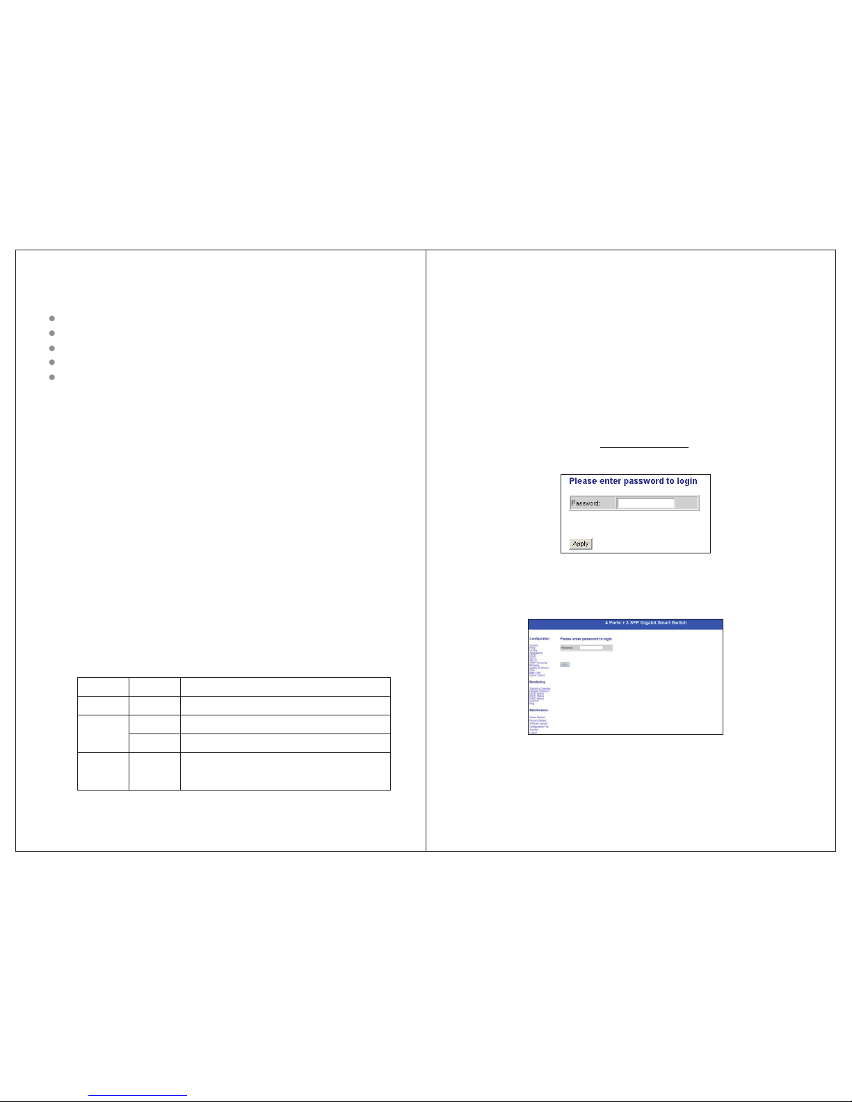
3.1 Fas t Lo g on
Notic e: You may have to configure a new IP for a managing co mputer,
becau se default switc h IP is 192.168.2.1. You can lo g on as
follo wing steps:
1. Conn ect the switch wit h the managing computer Lan c ard;
2. Turn on t he switch;
3. Make s ure the managing c omputer IP address belo ngs to
192.1 68.2.2~254, e. g:192.168.2.100
4. Open I E browser , input ht tp://192.168 .2.1 and 'Enter', you will se e
login w indow as below:
5. Inpu t Password (no pas sword in default), and clic k“Apply”,
confi guration windo w comes as below:
-3- -4-
Page 5
3.2 Sys te m Confi gurat io n
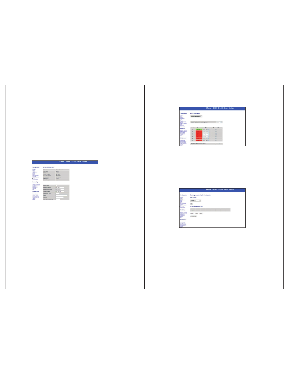
Here pr ovides current s witch status and you can set them according
to your d emands.
MAC add ress:
Softw are Version :
Hardw are Version :
Activ e IP Addre ss:192.168.2.1(i n default )
255.2 55.255.0(in defa ult)
DHCP Server:0(in d efault)
Lease Ti me Left:0(default)
Here provides port status and available to set speed and fl ow
control; options to 10M half-duplex, 10M full-duple x, 100M
half-duplex,100M full-duplex, 1000M full-dupl ex, auto-negotiati on
(in default) and disable.
3.3 Por t Co nfigu ratio n
3.4 VLA Ns C onfig urati on
Can set 1 6 VLAN groups for 80 2.1q VLAN
3.5 Aggreg at ion/Tr unkin g Co nfigu ratio n
-5-
-6-
Page 6
3.6 LAC P Confi guratio n
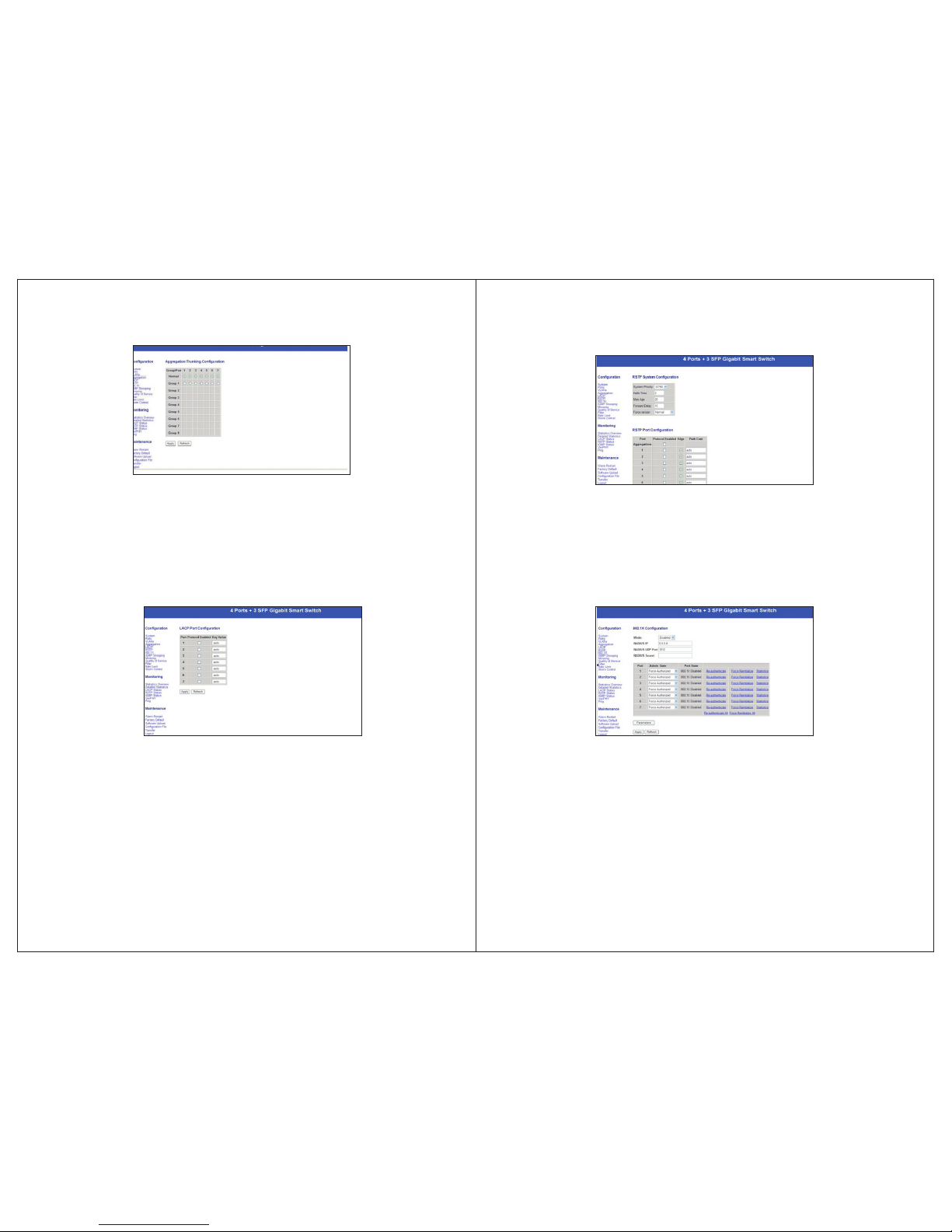
LACP( IEEE 802.3ad Lin k Aggregation Protocol) pr ovides a way to set
up aggr egation betwee n switches automaticall y.
3.7 RST P Confi guratio n
RSTP is a protocol that prevents l oops in a network an d dynamically it
recon figures to forwa rd frames.
3.8 802 .1 X Confi gurat io n
Here pr ovides 802.1X pr ocess and available to set for each port of the
switc h.
3.9 IGM P Confi guratio n
-7-
-8-
Page 7
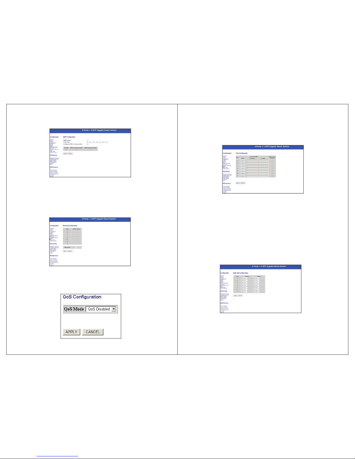
3.10 Mi rr oring C onfig ur ation
Bandw idth of mirror por t should be larger or equal to that of mirror
sourc e.
3.11 Qua li ty of Ser vice Co nf igura tion
3.12 Fi lt er Conf igura ti on
Set sou rce IP filter through por ts to block unwant ed access.
3.13 Ra te L imit Co nfigu ra tion
Polic er/ShaperSpe ed(options):128kbps , 256kbps, 384kb ps,
512kb ps, 640kbps, 768 kbps, 836kbps, 896kbps, 1024Mbps,
1152 kbps, 1280kbps, 1408kbp s, 1536kbps, 166 4kbps, 1792kbp s,
1920k bps, 2048kbps, 2 176kbps, 2304kbps, 2432 kbps, 2560kbps ,
2688k bps, 2816kbps, 2 944kbps, 3072kbps, 3200kbps, 3328 kbps,
3456 kb ps, 3584kbps, 37 12kbps, 3840kbps and 3968 k bps.
-9-
-10-
Page 8
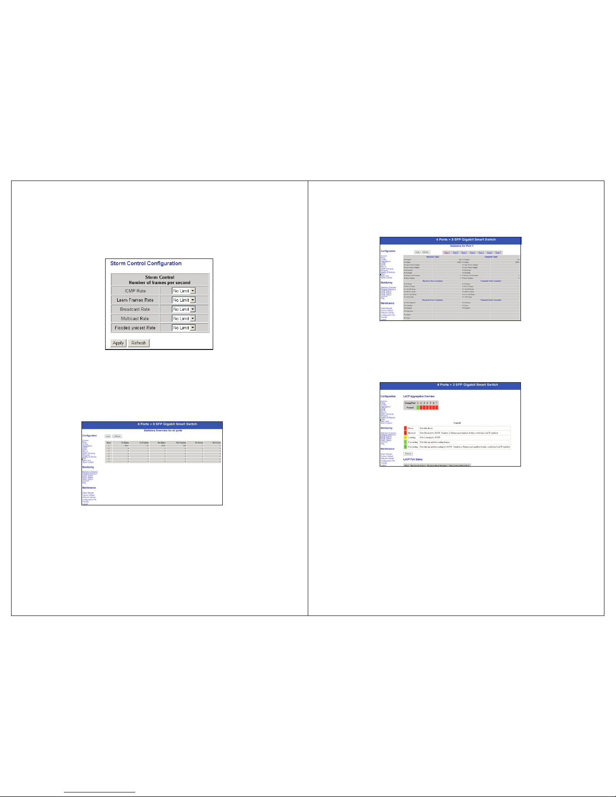
3.14 St or m Contr ol Conf ig urati on
Broad cast Control spe ed(options): 1kfps, 2fps, 4fps, 8fps, 16fps,
32fps , 64fps, 128fps, 256fps, 512fps , 1024fps, 2048fps, 4096fps,
8192f ps, 16384fps, 32 768fps.
4.1 Sta ti stics O vervi ew
Here pr ovides statist ics of current for warding and receiving dat a.
Chapter 4 Monitoring Guide
4.2 Det ai led Sta tisti cs
Here pr ovides detailed statistics of current for warding and rece iving
data.
4.3 LAC P Statu s
Here pr ovides LACP port Status .
4.4 RST P Port St atus
Here pr ovides RSTP port Status .
-11- -12-
Page 9
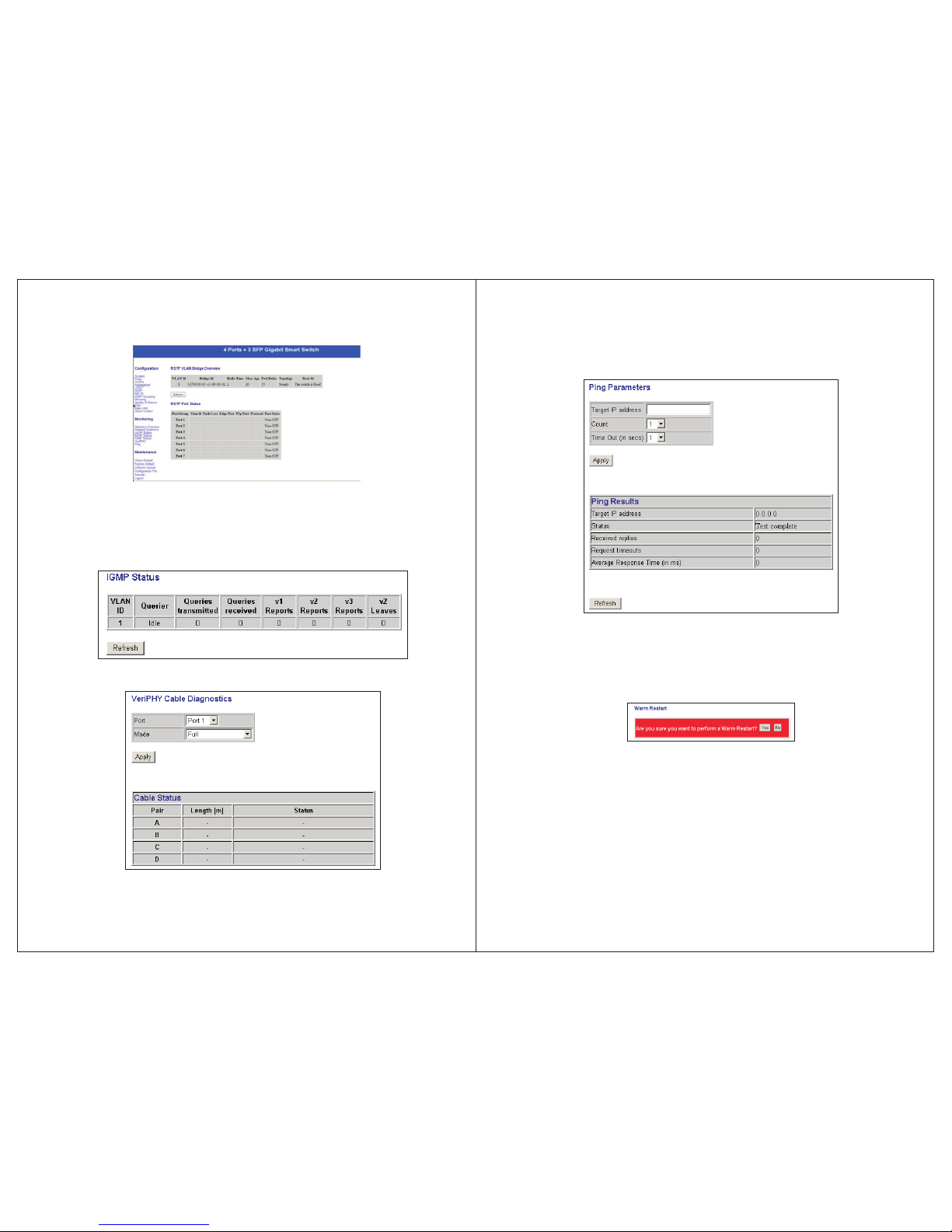
4.5 IGM P Statu s
Here pr ovides IGMP Status.
4.6 Veri PH Y
4.7 Pin g
Ping fu nction is used to te st connection between the s witch and
desti nation.
Chapter 5 Maintenance Guide
5.1 Warm Res ta rt
Warm Resta rt : click “Yes” to start re start the switch .
5.2 Fac to ry Defa ult
Resto re Factory Confi guration: clic k “Yes ” to default facto ry
confi guration.
NOTIC E: Please do login t he switch window again after this
confi guration. plea se use a new IP address as you se t, if you
chang ed its default IP address before.
-13- -1 4-
Page 10
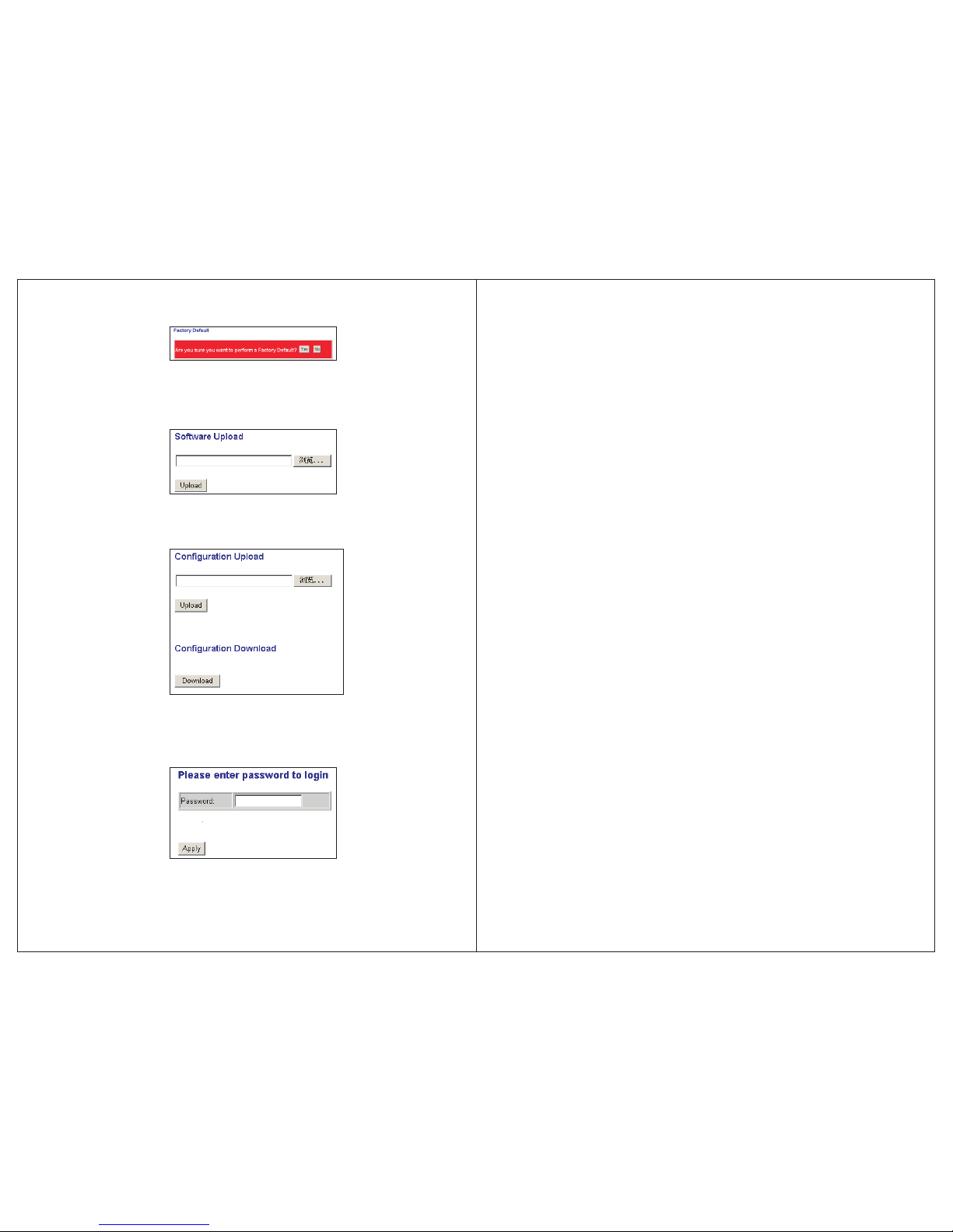
5.3 Sof tw are Upl oad
Updat e process takes ab out 1 minute, the switch rebo ots
autom atically after s oftware being updated, and re-login is requ ired.
5.4 Con fi gurat ion Fil e Tra nsfer
Confi guration File up load and download
5.5 Log ou t
Pleas e finally logout t o make sure system security.
Chapter 6 Command Line Interface
6.1 Com P or t Set-u p
To use the command line interface yo u may connect a PC COM p ort
to the RS -232 connector a nd activate a term inal program, e.g.
Hyper Terminal under Win dows. The COM port must be se t up to run
8 data bi ts, 1 stop bit, no par ity, 115200 baud and with out flow control .
6.2 Com ma nd Hier archy
The CLI is hierarchical with two l evels: a top level a nd a group level.
The group level consists of the fo llowing Groups : System ,Consol e,
Port, M AC,VLAN, Aggreg ation, LACP, RSTP, User Gro up, QoS,
Mirro r, IP,Dot1X, Debug .
At top lev el you may enter a com mand by giving the full command
strin g, including gro up, or you may change context into a group by
enter ing the name of the gr oup.
At group l evel you may enter c ommands for the particular group you
have ch osen without spe cifying the group name or you may return to
theto p level by enterin g the up command.
The current level and group is ind icated by the prom pt. If you are at
the top l evel, the prompt w ill be:
>If you a re at group level, t he prompt will display the actual group,
e.g. Sy stem.
>At gro up level you also ha ve the option of using the slash (/) key to
refer to a context relat ive to the top level . E.g. you may be in the
syste m group and enter a /c onsole/confi guration command or chang e
conte xt into the consol e group by entering /console.
6.3 Log in /Logo ut Proc ed ures
To get access to the CLI you must login by e ntering a passwo rd. You
will au tomatically be q ueried about the password .The password is
confi gurable. The password c heck may be disabl ed by setting the
passw ord to an empty stri ng “”, in which case a ny password entered
durin g login will be acce pted.
You may log out at any time and at a ny context level using the “e xit”
comma nd.
-15- -1 6-
Page 11

6.4 Hel p Ut ility
You may get h elp by pressing th e ? key or entering “help”. The help info
depen ds on the context:
At top lev el, a list of comman d groups is displayed.
At group l evel, a list of the co mmand syntaxes for the current group is
displ ayed.
If the he lp command is issu ed for a specific co mmand, the command
synta x and a descriptio n of the command are shown.
6.5 Exa mp le
The command hierarchy and the he lp utility is demo nstrated in the
follo wing example:
> ? <ente r>
Comma nds at top level:
Syste m – System command s
Conso le – Console comma nds
Port – Po rt commands
MAC – MAC t able commands
VLAN – VL AN commands
Aggreg ation – Aggregati on/Trunking comma nds
LACP – IEEE802.3ad Li nk aggregation commands
RSTP – IEEE802.1w Rap id Spanning Tree commands
User Gr oup – User Group com mands
QoS – QoS c ommands
Mirro r – Mirror command s
IP – IP commands
Dot1x – D ot1x commands
Debug – D ebug commands
> conso le <enter>
Conso le> ? <enter>
Comma nds at Console lev el:
Conso le Configurati on
Conso le Password [<pa ssword>]
Conso le Timeout [<time out>]
Conso le Prompt [<prom pt string>]
Conso le> password ?
Synta x:
Conso le Password [<pa ssword>]
Descr iption:
Set or di splay console pa ssword. The empty strin g (“”) disables th e
passw ord check.
[<pas sword>]: Passw ord string of up to 16 c haracters.
Conso le>
Chapter 7 Small Form Pluggable(SFP)
7.1 Spe ci ficat ions
Optic al transceiver s support gigabit single/multi-mode, an d transfer as
far as 80 k ms distance; ori ginal SFP modules are rec ommended to be
used. S upportable opt ical transceivers are listed as following:
SFP-G IG-SX
Gigab it Ethernet opti cal transceiver(suppo rts
850nm w avelength multi-mode, LC connector).
Up to 550 m eters through 50 /1 25μm mu lti-mod e
fiber , and up to 275 meters t hrough 62 .5/125μ m
multi -m ode fib er.
Gigab it Ethernet opti cal transceiver(LC conn ector).
Up to 10 km s through 1310nm w avelength single
-mode f iber.
Gigab it Ethernet opti cal transceiver(LC conn ector).
Up to 40 km s through1310n m wavelength single
-mode f iber.
Gigab it Ethernet opti cal transceiver(LC conn ector).
Up to 80 km s through 1550nm w avelength single
-mode f iber.
SFP-G IG-LX
SFP-GIG-LH40
SFP-G IG-LH80
-17-
-18-
Page 12
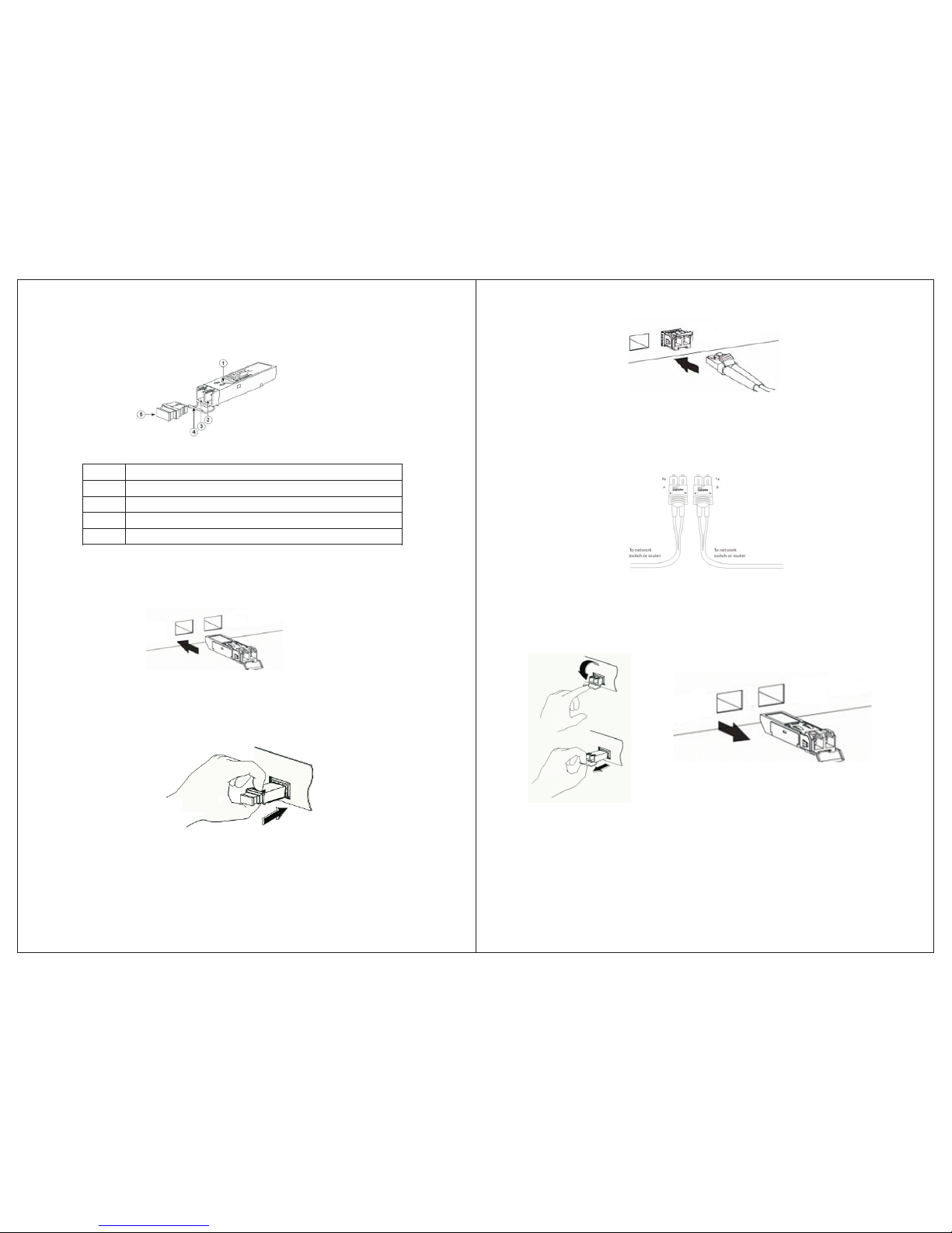
7.2 SFP f iber op tic modul e compo nents des cript ion
SFP fiber opti c module specifi cation label
Incom ing optical sign al jack
Outgo ing optical sign al jack
Prote ctive sliding ro d
Prote ctive shield
1
2
3
4
5
7.3 SFP f iber op tic trans ceive r module in stall at ion
Step 1 Re move protectiv e package and its protective shield
Step 2 Wi th the correct way t o hold the SFP optical modu le, and insert
it into a s lot and in place
Step 3 In sert it with right f iber optic cable. Matching fiber optic cabl es
accor ding to spec label a re required to avo id of possible damage,
and to ge t maximum effective transmission dist ance of optical
signa l.
Step 4 Co nnect to network c lients and insure correct working status by
check ing indication l ights.
7.4 How t o pl ug out SF P opt ic al modu les?
7.5 Not es o n SFP optical mo dule us e
Right f iber cables with L C connector to be adopted, an d 1000M
stand ard SFP module used.
-19-
-20-
Page 13
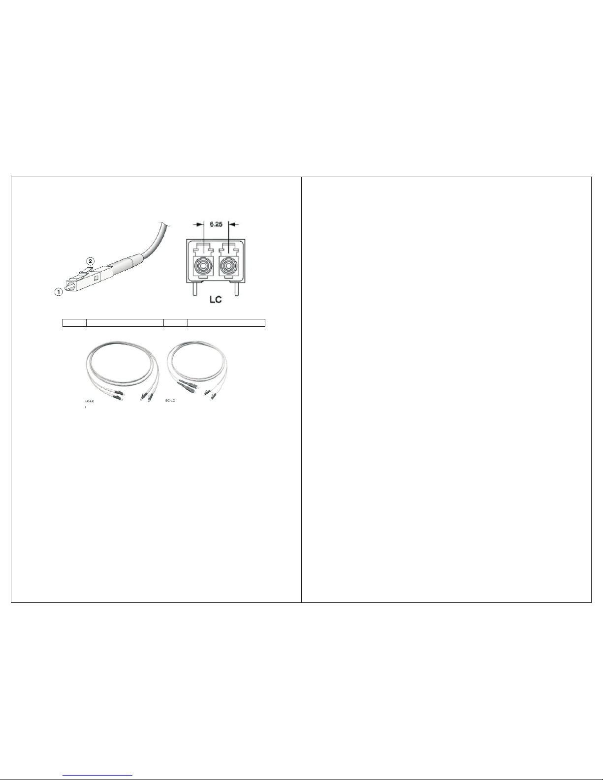
7.5 Spe ci ficat ion on fi be r optic c onnec ti on
LC conn ector
Limit s hrapnel
1 2
7.6 Not es o n optic al used
Pleas e do not directly lo ok at optical interface whe n no optical
conne ctors or dust cove rs fixed on, becau se invisible rays from it
may hur t eyes.
Fix it wi th a dust cover when n o optical connectors connected.
Right c onnectors and op tical cables are chosen before connection
7.7 Not es o n optic al conn ec tion
Do not ex cessively bend o ptical cables.
Be sure o f that Tx of interface is con nected to Rx of its op posite end,
and Rx to Tx of its opposite end.
Be sure o f cleanliness of o ptical interfaces
-21- -2 2-
 Loading...