

Page 1
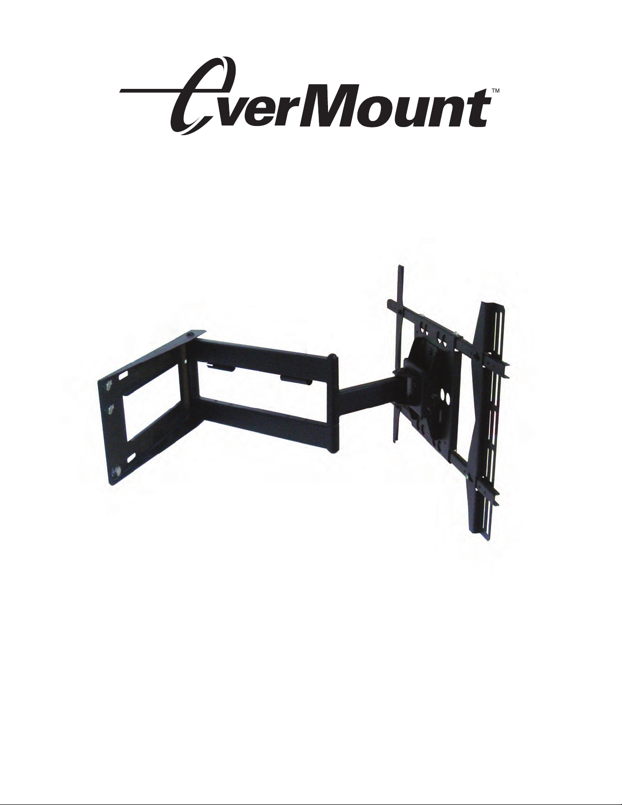
EM-PLA/PLAB INSTALLATION GUIDE
Large Universal Cantilever Mount
Features
• Designed for 40"-58" Flat Panels
• Maximum weight capacity up to 125 lbs
• VESA compliant
• Lift and Lock for easy installation
• Integrated cable management
• CUL Approved
Page 2

WARNING
NB012010
•
THE WARRANTY WILL ONLY BE VALID IF YOU FOLLOW THE INSTRUCTIONS CAREFULLY.
•
If you do not understand the instructions, or are not sure you can follow them safely, contact a qualified
contractor.
•
Improper installation may cause serious injury and/or damage. It is recommended that a qualified
contractor install the EM-PLA / EM-PLAB.
• Make sure that the wall you plan to use will safely support four times the combined weight of the
mounted equipment, including its accessories.
• Under no circumstances should this product be mounted to metal studs.
• Never exceed the maximum load capacity of 150 lbs.
• A second person will be required to assist with several steps.
• Before beginning check that you have all the parts listed. Call 1-866-604-6966 to acquire any
missing parts.
TABLE OF CONTENTS
Installation tools..................................................................
Parts list..............................................................................
Mounting location.................................................................
Installation template.............................................................
Wall preparation..................................................................
Mounting to the wall............................................................
Assemble the adaptor plate.................................................
Configuring adaptor plate....................................................
Selecting the mounting hardware........................................
Attaching the display............................................................
Using cable management....................................................
Adjusting the display..........................................................
Maintaining the unit............................................................
10
3
3
3
4
4
6
7
7
7
8
9
9
2
Page 3
Electronic Stud Locater (Wooden stud installation only)
NB012010
Variable Speed Electric Drill
Hammer Drill (Concrete installation only)
Drill Bits:
1/4" (6 mm) drill bit (Wooden stud installation only)
1/2" (13 mm) masonry drill bit (Concrete installation only)
Hammer (Concrete/Masonry installation only)
Ratchet Wrench with 11/16" (17 mm) socket
Philips head screwdriver
Description
ID
Philips M4*35mm
A
Philips M4*45mm
B
Philips M5*35mm
C
Philips M5*45mm
D
Philips M6*35mm
E
Philips M6*45mm
F
Philips M8*35mm
G
Philips M8*45mm
H
I
M8*15 mm screw bolt
8.2*1.5*16 metal Washer
J
5 mm Allen wrench
K
5/8" spacer
L
3/4" spacer
M
Round Washer
N
Square Washer
O
3/8"-3 1/2" Lag Bolts
P
Q
Wall anchor 6
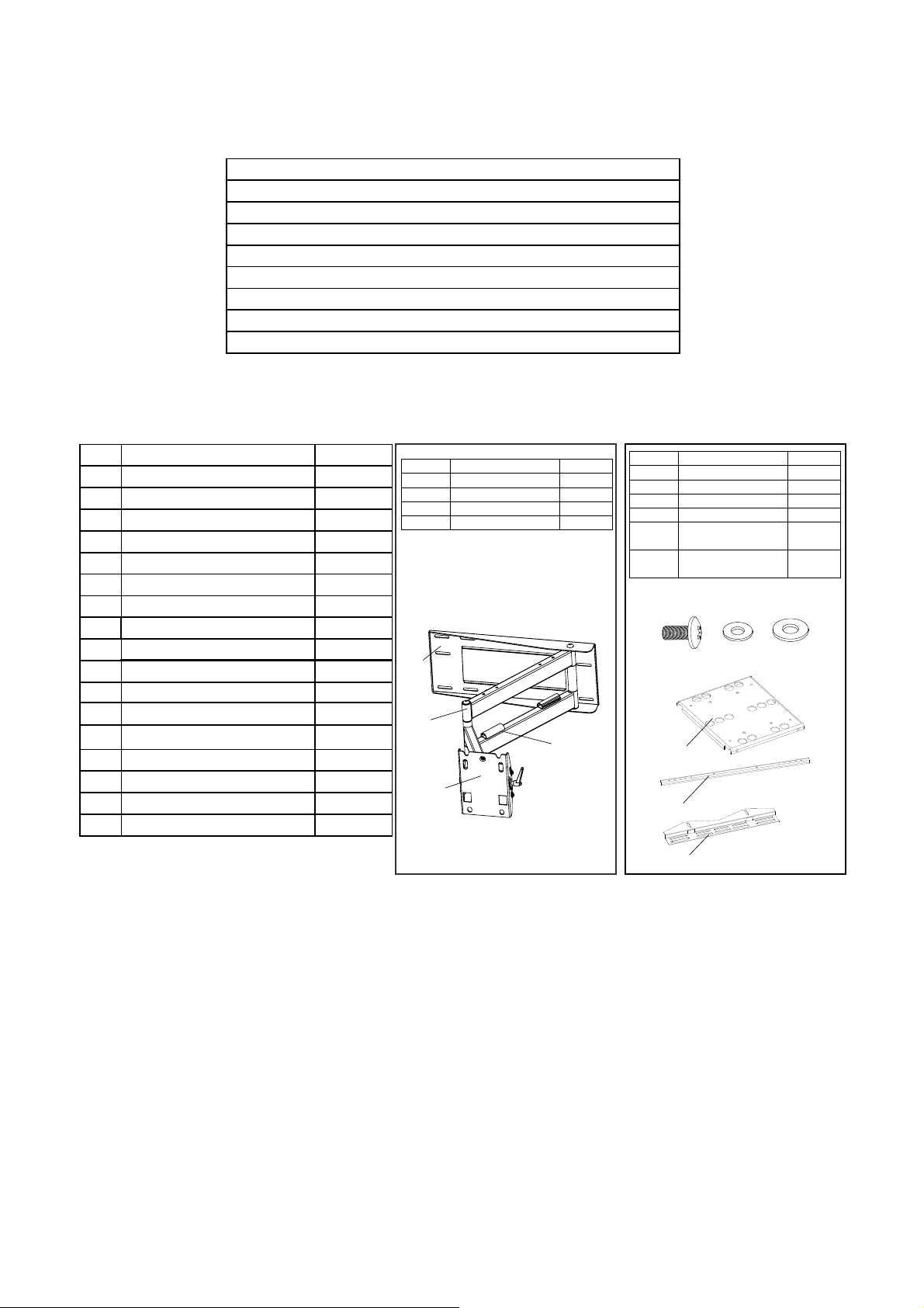
Installation tools
Parts List
Qty
4
4
4
4
4
4
4
4
4
4
1
4
4
6
4
6
ID
a)
b)
c)
d)
a)
d)
Description
Wall Plate
Cable Panel
Mount Head
Arm Assembly
c)
Qty
1
1
1
1
b)
ID
e)
f)
g)
h)
i)
j)
Description
Adapter Panel
Adapter Bar
Adapter Bracket
Screw M6
Metal Washer
(∅6x∅10x1.2)
Metal Washer
(∅6x∅13x1.2)
h)
i)
e)
Qty
1
2
2
8
4
4
j)
f)
g)
Step 1: Determine the Mounting Location
To provide maximum viewing flexibility, the EM-PLA mount is capable of a wide range of motion.
This allows the plasma/LCD unit to be put in almost any position. When selecting the mounting
location make sure there is adequate space on all sides of the panel to allow for full range
articulation of the bracket.
3
Page 4
Step 2: The Installation Template
NB012010
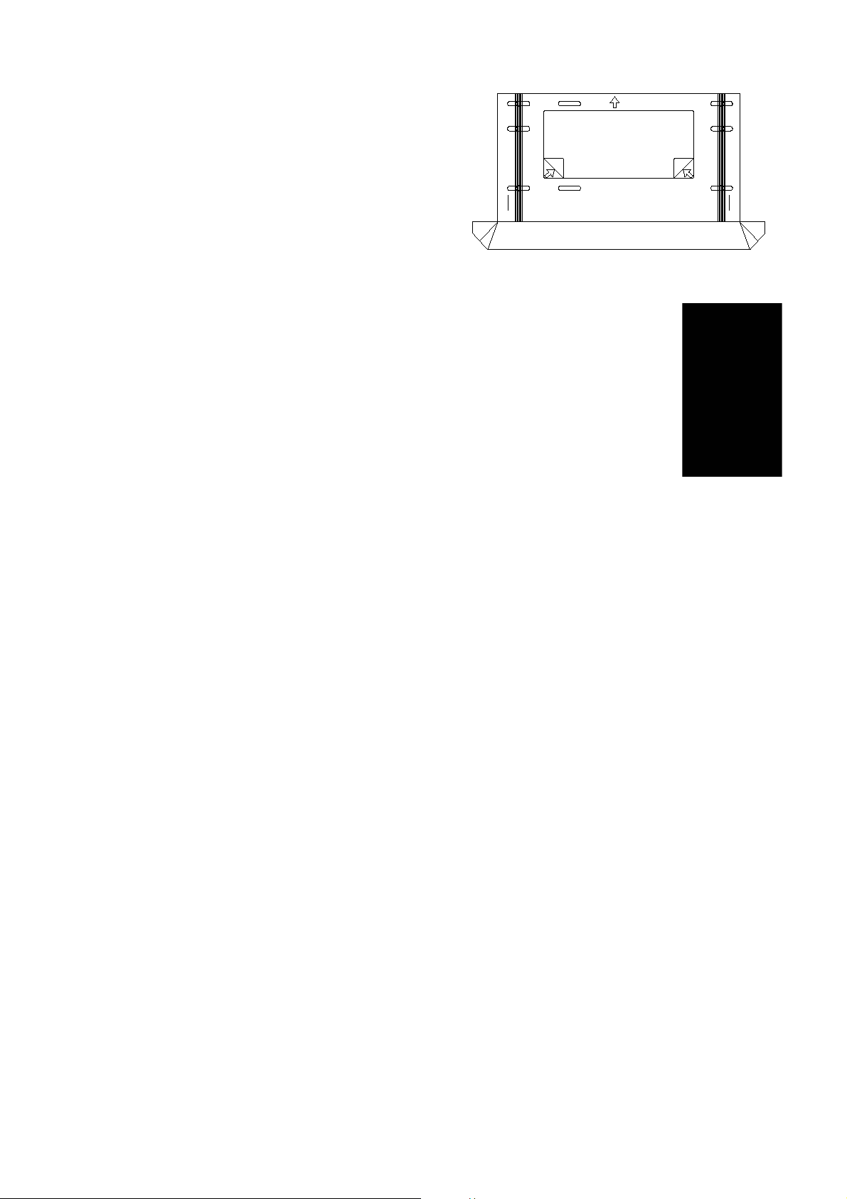
The installation template is designed to make
mounting the wall plate faster, easier and
more precise. The template includes a built in
dust channel to reduce clean up (Fig.1).
UP
REMOVE
REMOVE
Step 3: Preparing the Wall
Fig.1
Follow the instructions based upon your mounting surface:
3a Wooden Stud
3b Concrete/Masonry
3c Cinder Block
Step 3a: Mounting to Wooden Studs
The EM-PLA can be mounted onto two wooden studs, with center to center distances
between 15" and 17" (38-43 mm).
Using an electronic stud finder (Fig.2), locate the center of the two wooden studs at the
desired mounting location. Mark the stud center positions directly on the wall. Connect
the stud marks with a horizontal line and find the center between them to represent
where you wish the center of the screen to be located. Be sure to measure and mark the
center of this horizontal line.
Place the template on the wall, and then remove the tape strip from the back of the template.
Pin the template to the center mark on the wall. Using a level (bubble or laser ), level the
guide, and then press the adhesive backing against the wall to hold the guide in place.
Fig.2
Note:
Depending upon the wall texture, you may need to use tape to hold the template in position.
Using a 1/4" (6 mm) drill bit, drill 6 pilot holes into the center of the studs (through the mounting hole
cut-out sections of the template), down to a depth of 3" (76 mm).
Carefully remove the template from the wall and discard. Hold the template in an upright position
so as not to spill the collected dust..
4
Page 5
Step 3b: Mounting to Concrete/Masonry
NB012010
Hammer
WARNING
• NEVER drill into mortar joints!
• Concrete must be 2000 PSI density minimum.
The wall plate can be mounted directly to concrete/masonry walls. Remove the tape strip
from the back of the template, and place the template in the desired location. Using a
bubble/laser level, align the template and then press the adhesive backing to the wall
which will hold the guide in place.
Note: Depending upon the wall texture, you may need to use tape to hold the template in position.
Using a 1/2" (13 mm) masonry drill bit, drill 6 mounting holes 31/8" (80 mm) deep into the
concrete/masonry surface. Drill through the mounting hole cut-out sections of the template.
Carefully remove the template from the wall and discard. Hold the template in an upright position
so as not to spill the collected dust..
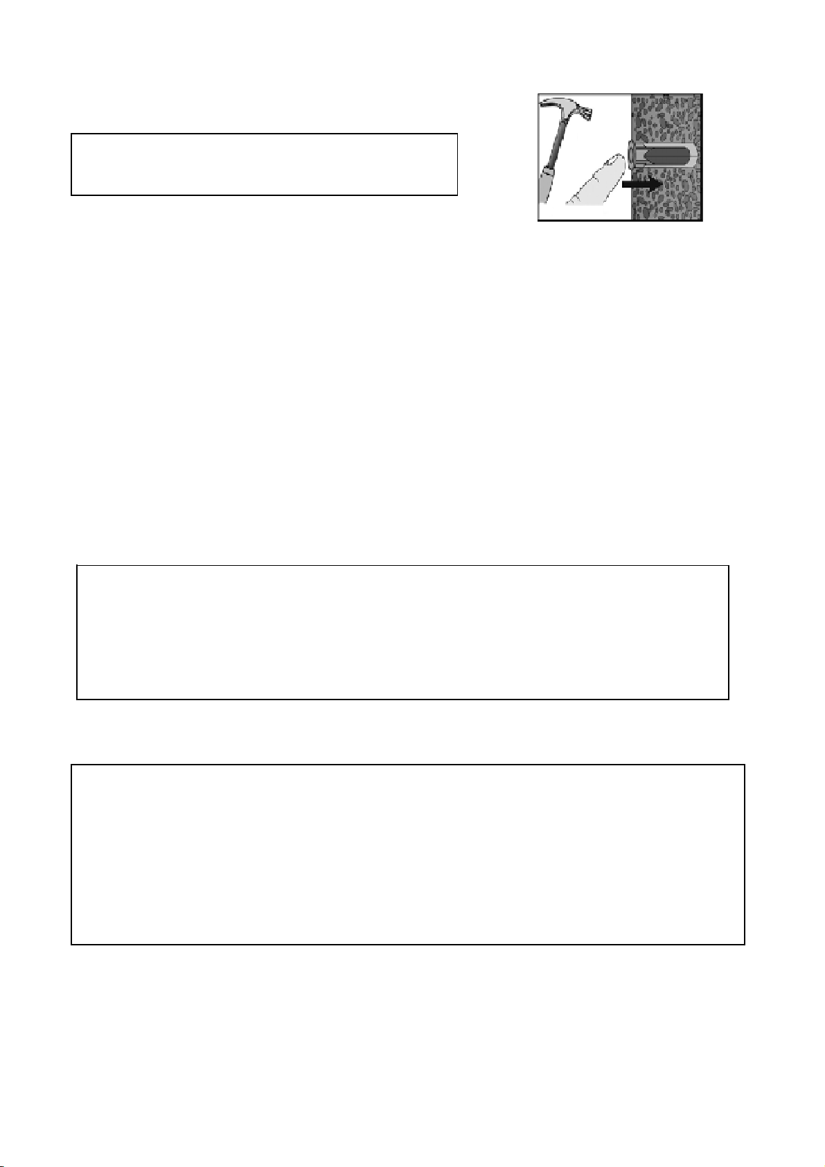
Gently
Fig.3
Push in
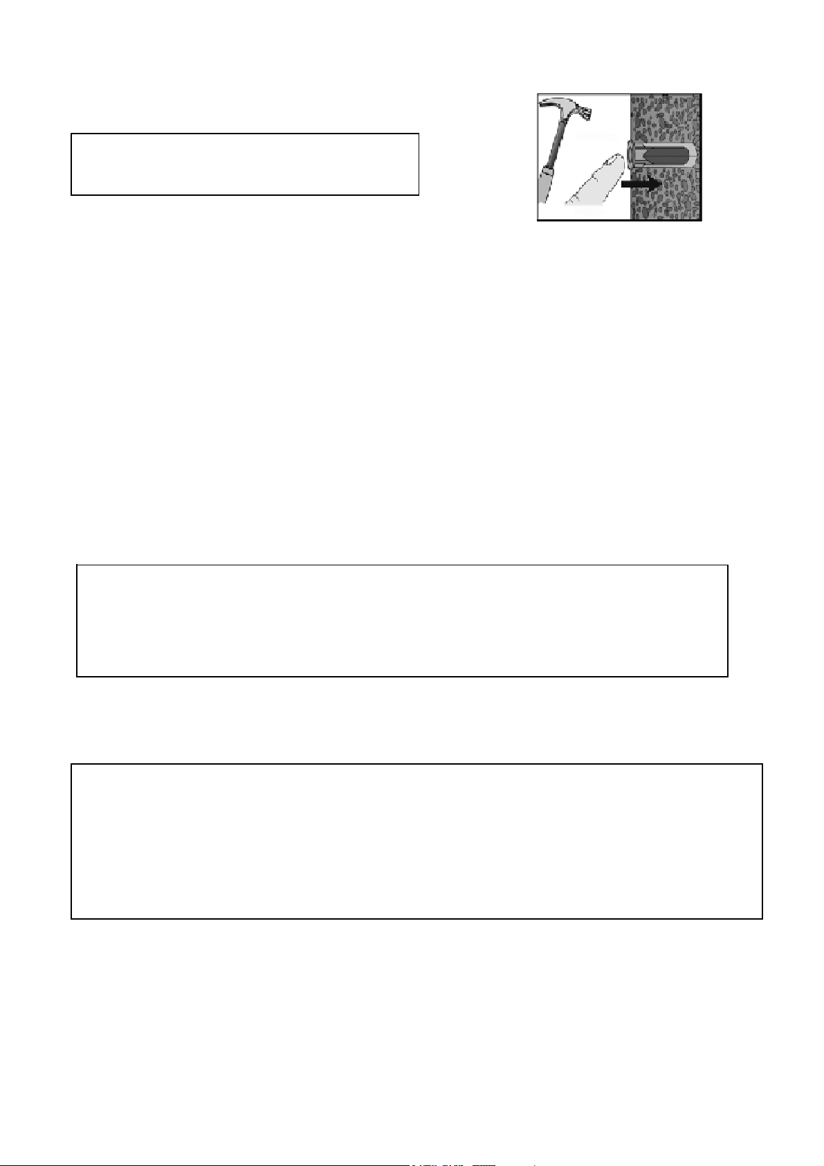
Insert wall anchors into the mounting holes,and lightly tap them flush to the wall with a hammer (Fig.3).
IMPORTANT
Masonry anchors MUST be seated firmly against the masonry or concrete. If mounting to a
masonry wall covered with drywall/plaster, counter sink a larger hole through the drywall/plaster
to the concrete/masonry surface overlapping the mounting hole, so that the anchor can be
seated directly against the concrete/masonry surface.
Step 3c: Mounting to Cinder Block
WARNING
. Cinder Block must meet ASTM C-90 specifications.
. Mount to solid portion of block,generally 1" from the sides.
. NEVER drill into mortar joints!
. Use standard drill set on slow speed/high torque setting. DO NOT use hammer drill on cinder block.
. Verify that you have a minimum of 1 3/8" of actual concrete thickness in the mounting hole,
before inserting the wall anchor.
The wall plate can be mounted directly to cinder block walls.
Remove the tape stripe from the back of the template. Using a bubble level, hold the template in a
level position and then press the adhesive backing against the wall to hold the guide in place.
5
Page 6
Note: Depending upon the roughness of the surface, you may need to hold the template in
NB012010
place with tape.
Using a 1/2" (13 mm) drill bit, drill 6 mounting holes 31/8" (80 mm) deep into the cinder block
surface. Drill through the mounting hole cut-out sections of the template.
Carefully remove the template from the wall and discard. Hold the template in an upright position
so as not to spill the collected dust..
Insert wall anchors into the mounting holes,and lightly tap them flush to the wall with a hammer.(Fig.3)
IMPORTANT
Masonry anchors MUST be seated firmly against the concrete or masonry, If mounting to
a wall covered with drywall/plaster,counter bore a hole through the drywall/plaster around
the mounting hole location,so that the anchor can be seated directly against the concrete
or masonry.
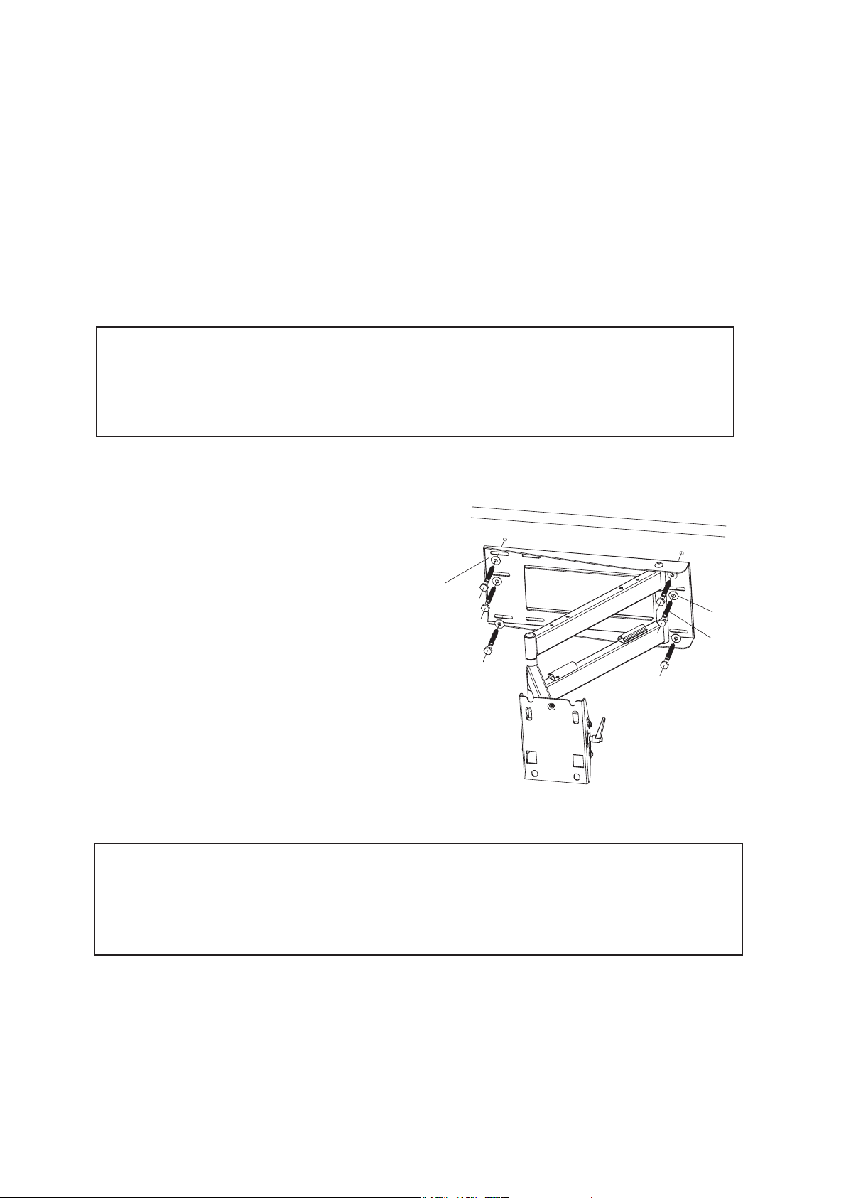
Step 4: Mounting to the Wall
Remove the cantilever assembly from the box.
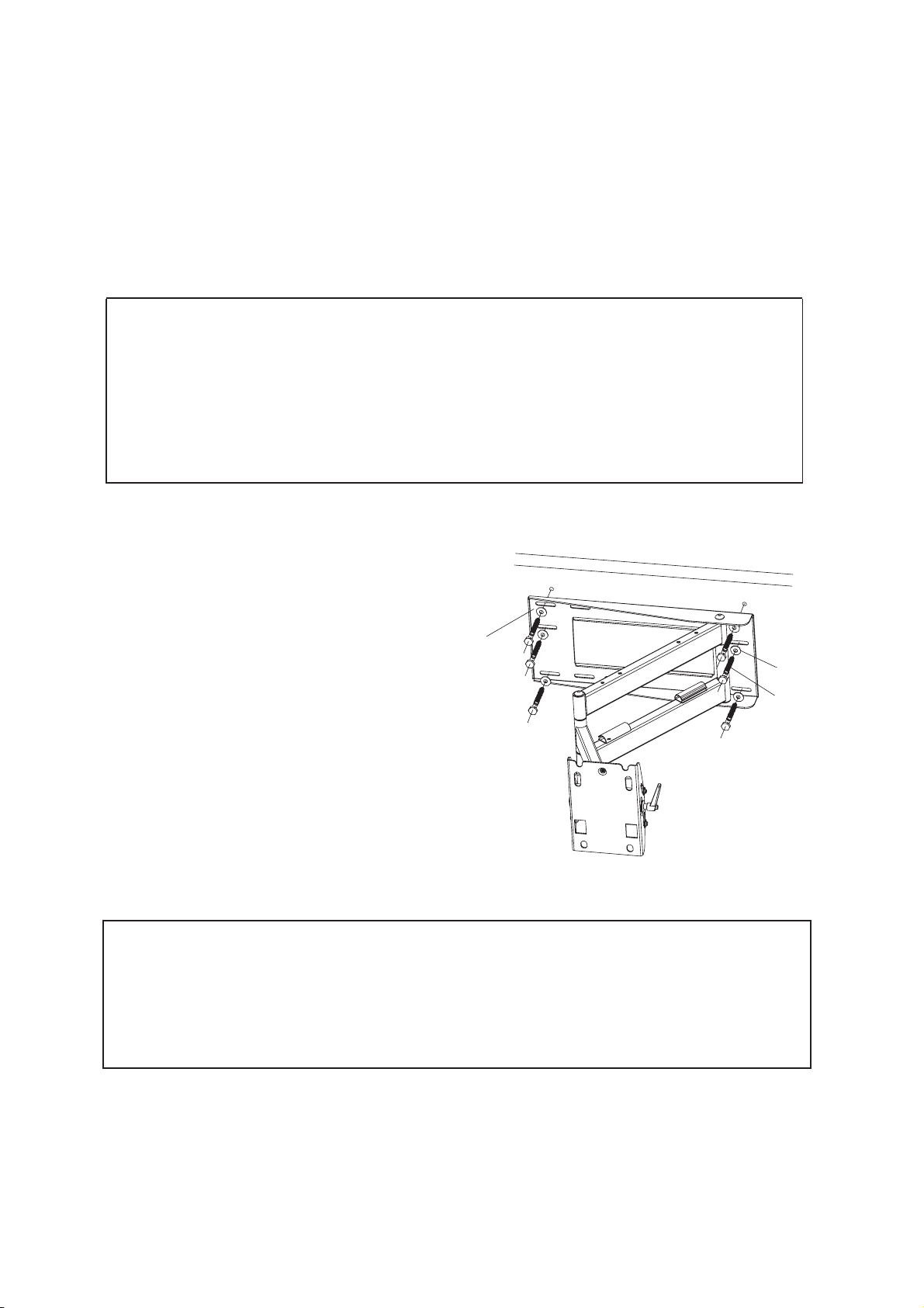
wall plate
With the help of an assistant, carefully hold the mount in
position over the mounting holes, and then securely bolt
the wall plate to the wall with supplied washers (N) and
3/8"-3 1/2" lag bolts (P). See Fig.4.
Fig.4
IMPORTANT
Tighten lag bolts so that wall plate is firmly attached to wall,but DO NOT over tighten.
The lag bolts can be damaged by over tightening which will strip their threading.
Final tightening of lag bolts should be done by hand using a ratchet wrench and socket.
round washer
3/8”-3 1/2” lag bolt
6
Page 7
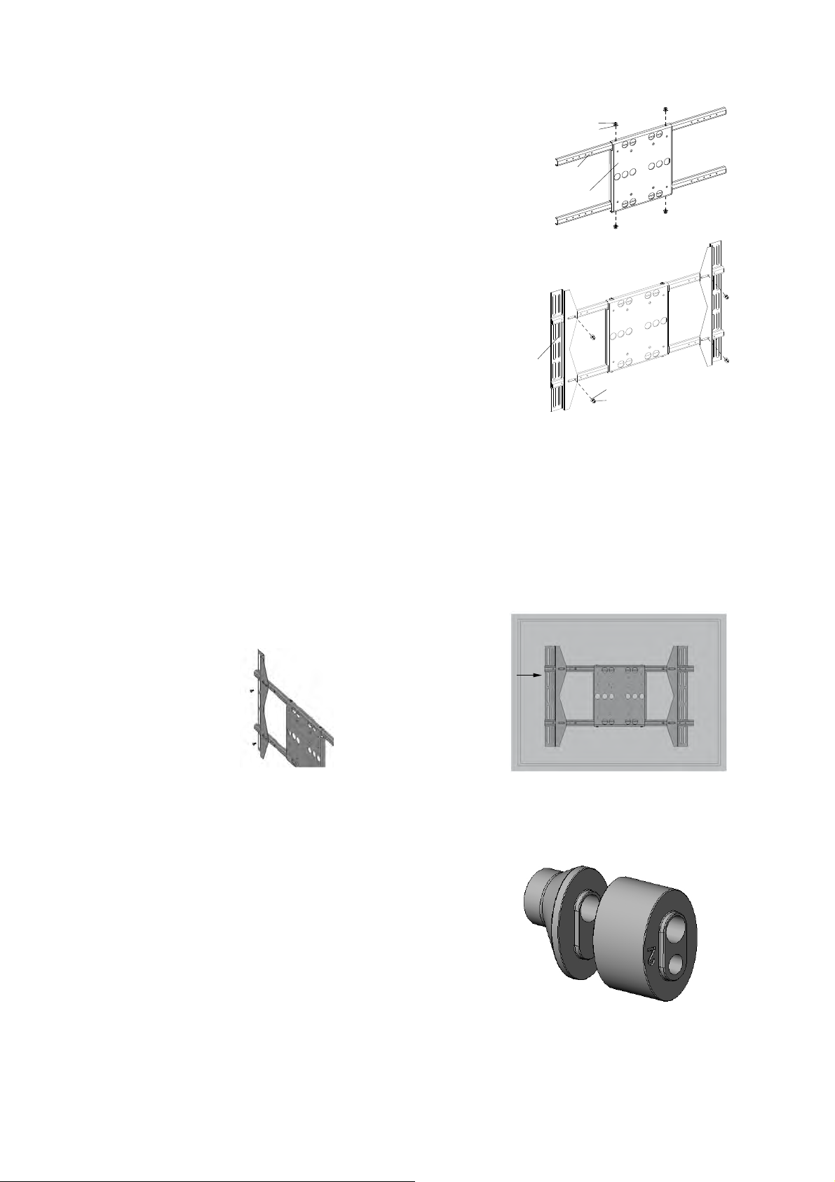
Step 5: Assemble the Adapter Plate
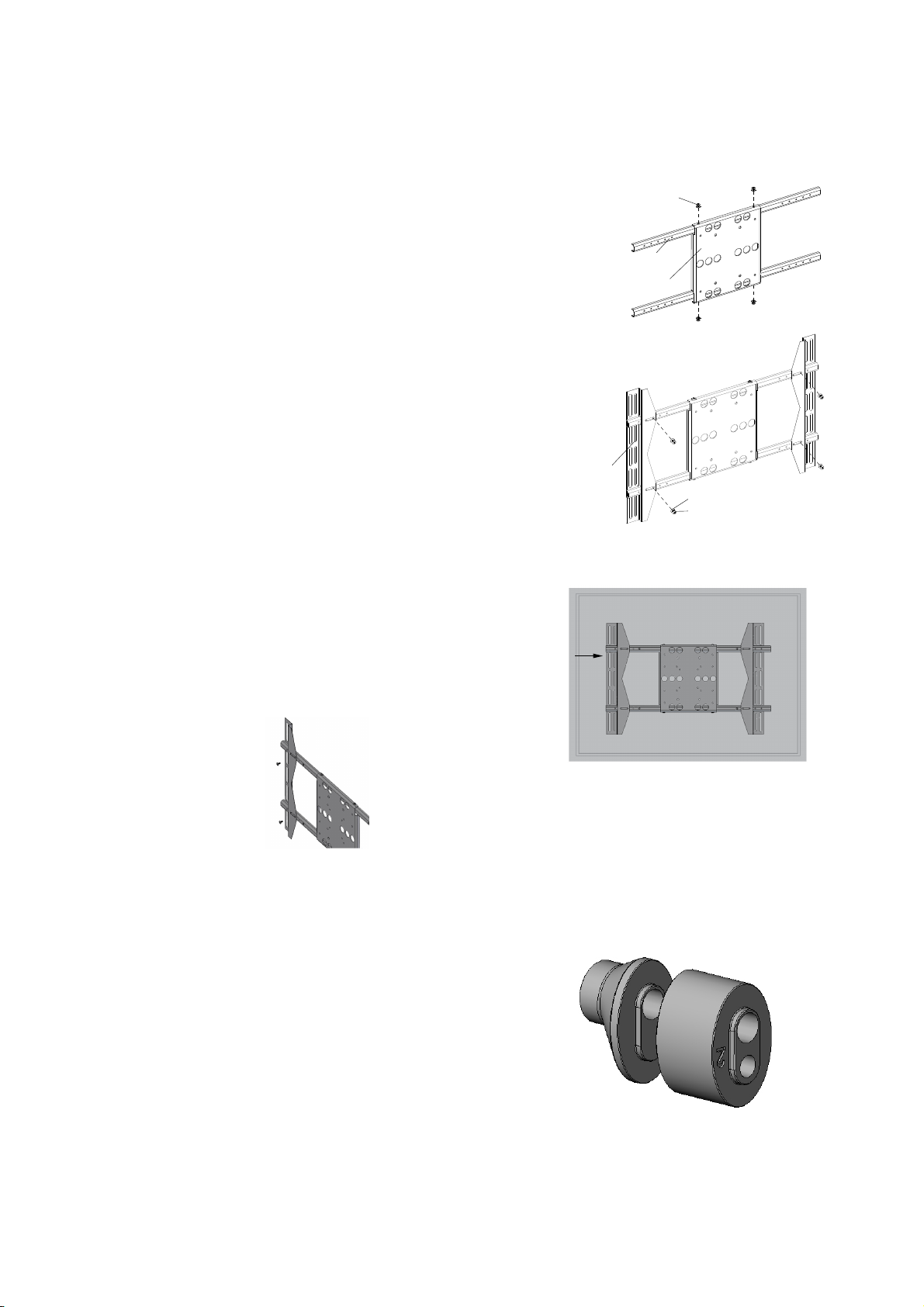
Attach the adapter panel to the adapter bars using four screws
and four metal washers (Fig.5.1.).
Attach the adapter brackets to the adapter bars using four
screws and four metal washers (Fig.5.2).
NOTE:In order to accomodate various panel sizes there are
five positions in which the brackets can be attached.
The adapter plate is of a universal design, and can be
attached to a wide range of flat panel display mounting
patterns up to VESA 400x600.
The easiest way to check for fit is to simply place the
adapter on the back of the display, with one mounting
bracket aligned with a set of vertical mounting holes (Fig.6.1).
Then, using the adapter's revolutionary rack and pinion selfcentering system, simply slide the other mounting bracket in
or out until it aligns with the second set of vertical mounting
holes (Fig.6.1). The adapter should now be horizontally
centered on the back of the flat panel display. In order to achieve
VESA 300mmx300mm mounting paterns, invert the mounting
brackets so that the mounting holes are on the inside.
Proceed to step 7 when the brackets are correctly aligned to
the mounting holes (Fig.6.2).
Fig.6.2
Adapter
Panel
Adapter
Bracket
Adapter
Bar
M6 Screw
Metal Washer
(¢6*¢10*1.2)
M6 Screw
Metal Washer
(¢6*¢13*1.2)
Step 6: Configure the Adapter Plate
Fig.5.1
Fig.5.2
Step 7: Selecting the Mounting Hardware
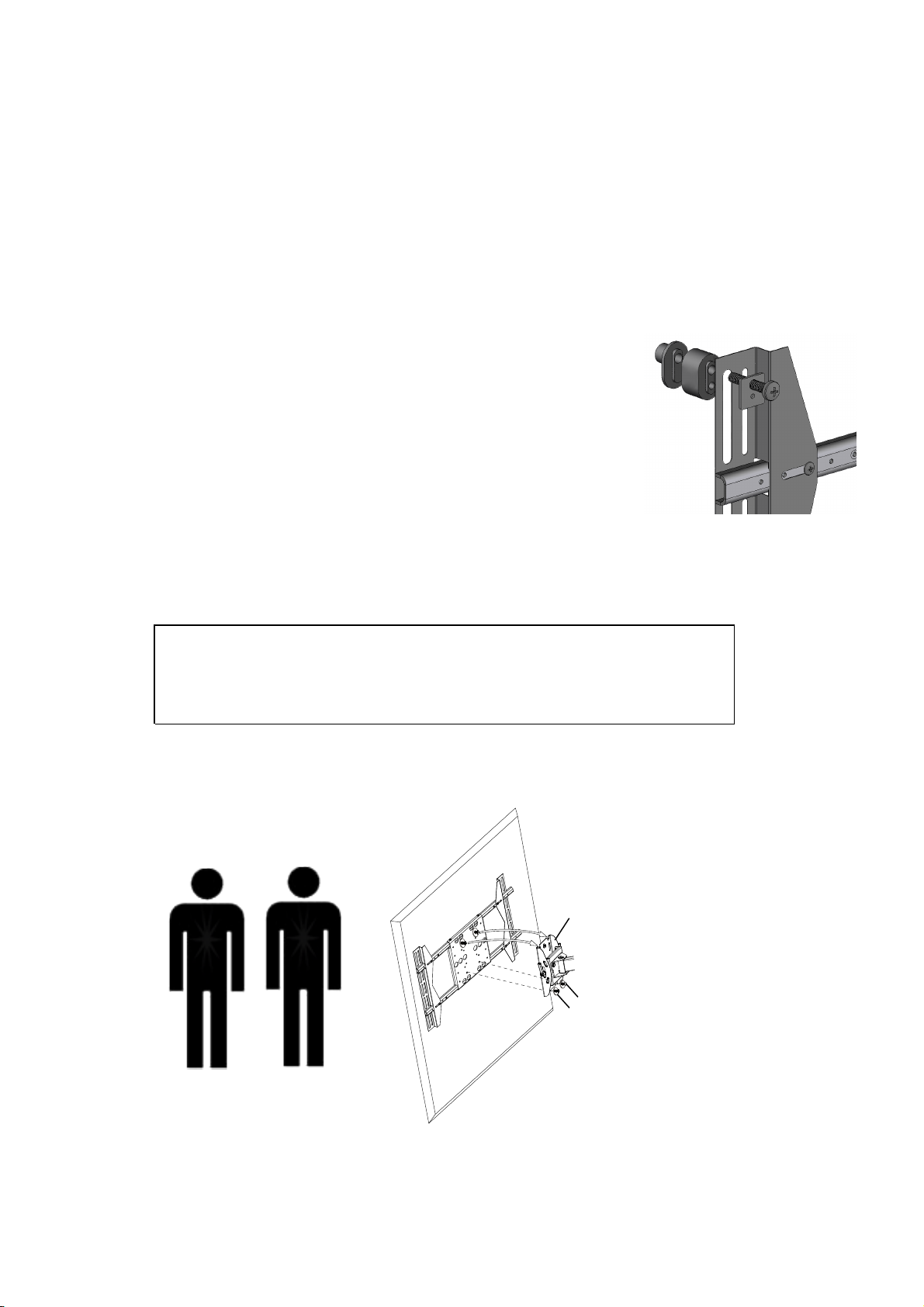
Some displays will require the use of a spacer.
There are two spacers provided:
5/8" (16 mm) round nose spacer (L)
3/4" (19 mm) block spacer (M)
(Fig.7).
Fig.6.1
Fig.7
7
Page 8
The spacers may be used individually,or may be snapped together to create one large
NB012010
stacked spacer.The spacers have been designed to snap directly into the mounting rail for
ease in handling, and also include two different mounting holes to manage the various screw
sizes.
Generally,the 5/8" (L) is used on displays with slightly curved backs and /or recessed
mounting lands. The 3/4" spacer (M) is used on displays with curved backs, and stacked
spacers(L&M) will be used on displays with deeply curved backs and/or protruding accessories.
Step 8: Attach the Display
Place the adapter down on the back of the flat panel display.Align the
left mounting rail with the mounting holes on the back of the display panel.
Center the rail vertically over the back of the display,and secure using
the selected mounting screws (A-H), square washers (O) and any
required spacers (L&M) (Fig.8).
Note: Use the segmented mounting slots on the rails as a
means for vertically centering the adapter.
Fig.8
Now slide the opposite mounting rail into position,align it with the mounting holes, and secure with the
mounting hardware.
IMPORTANT
DO NOT over tighten the mounting screws, or the display may be damaged.
NEVER use a power driver to tighten the mounting screws.
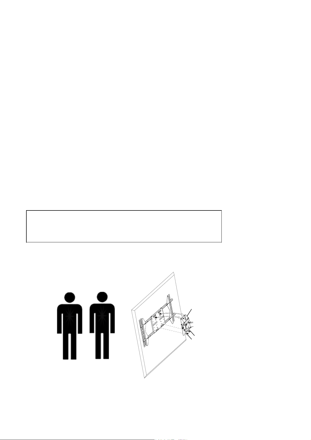
With the help of an assistant, carefully lift the display and attach it to the mount head.
Tighten the screws (Fig.8.1).
mount head
M8*15mm screw bolt
8.2*1.5*16mm metal washer
Fig.8.1
8
Page 9
Step 9: Using Cable Management
NB012010
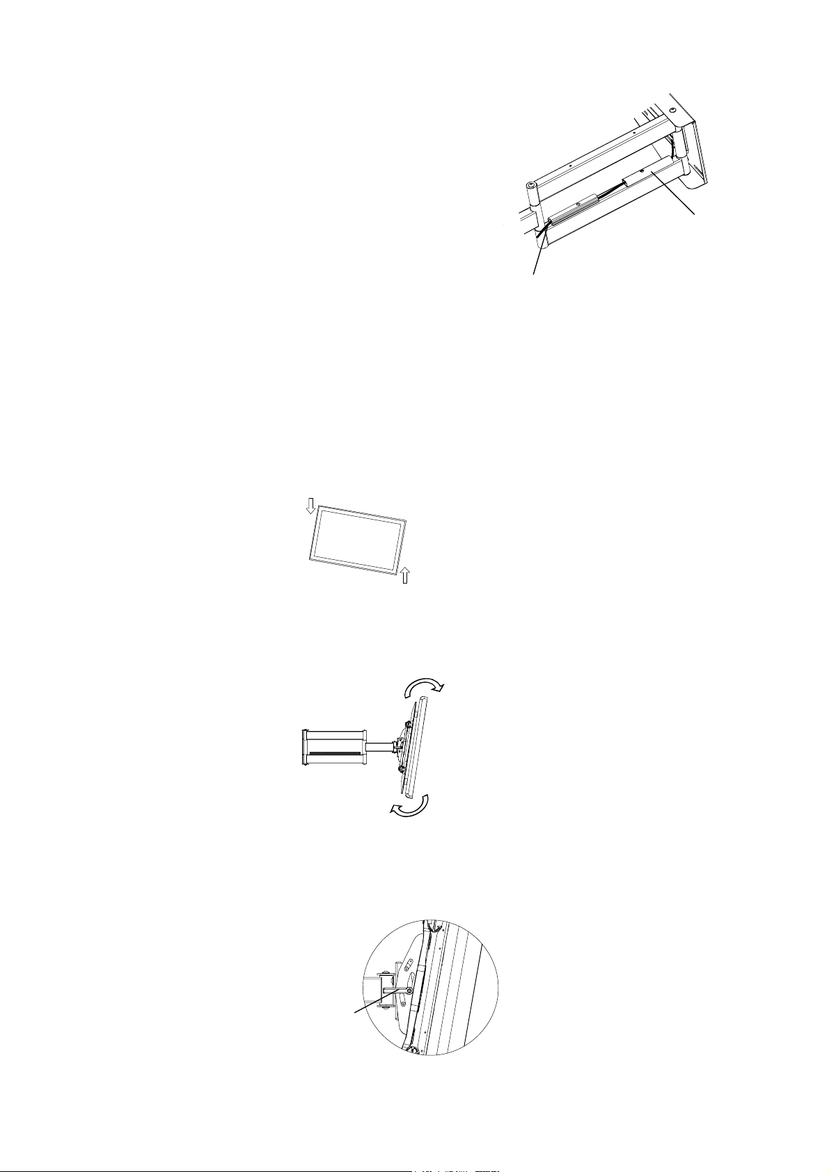
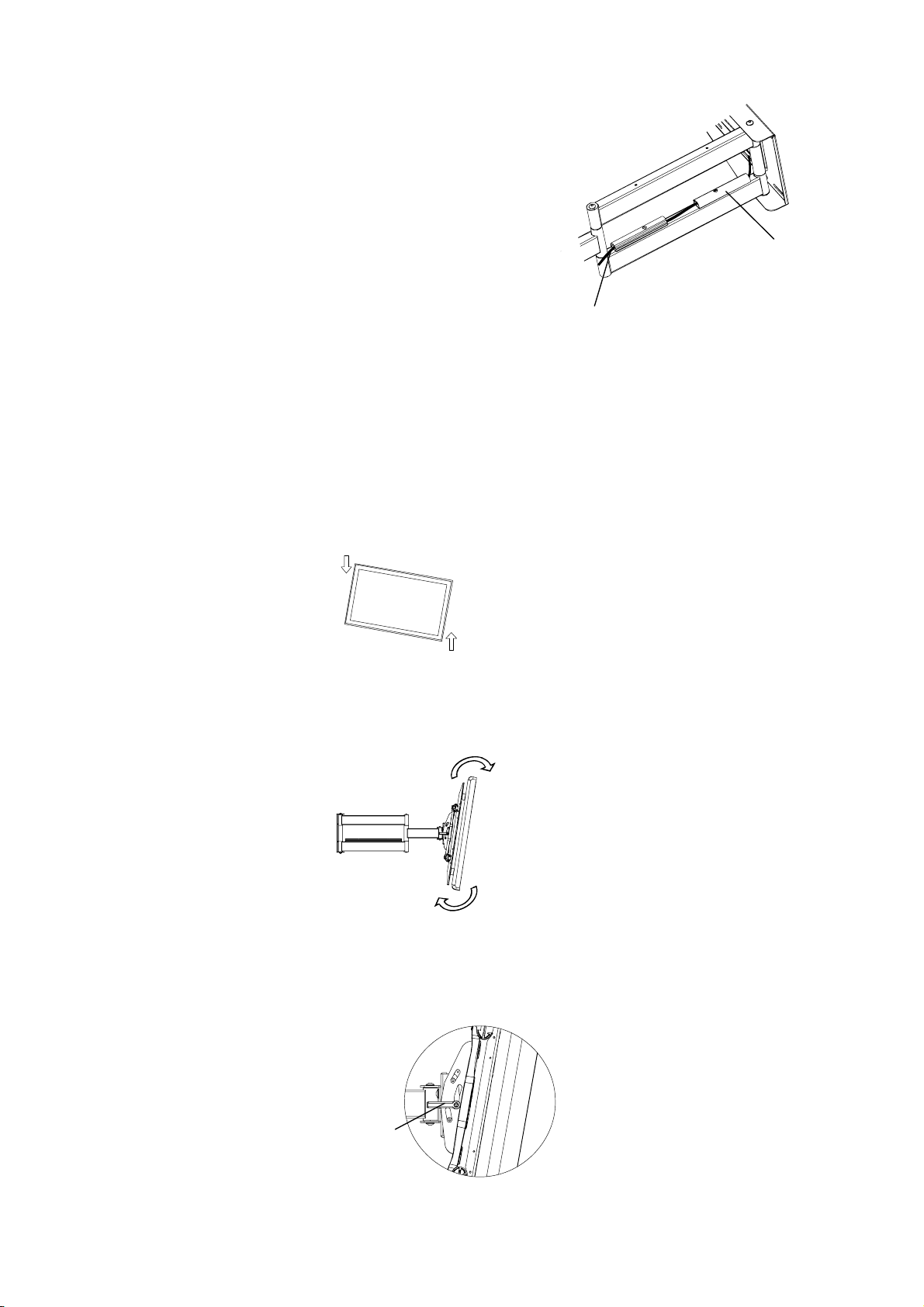
The EM-PLA includes a cable management system where cable can
be routed along the length of the arm assembly.
Route the display cable along the entrance of the cable
management slot.(Fig.10)
cable management
Note: For optimal performance, route the AC power
cable separately form the signal cables.
With all cables in place, pull the display in and out to be certain that the arm assembly
moves freely, without stretching or damaging the cables.
cable
Fig.9
Step 10: Adjusting the Display
The EM-PLA provides a wide range of adjustment possibilities to suit your environment.
Roll Control - Horizontal leveling of the flat panel display.
Grasp the edge of the display and roll it up or down into a level position (Fig.13).
Fig.13
Tilt Adjustment - Raising or lowering the screen to improve viewing angle.
Grasp the upper and lower edges of the display, and then turn it to the desired tilt angle (Fig.14).
Fig.14
To lock the tilt angle, tighten the tilt knob (Fig.15) securely.
NOTE: For heavier displays, never fully release the tilt knob without fully
supporting the display.
Fig.15
9
Page 10
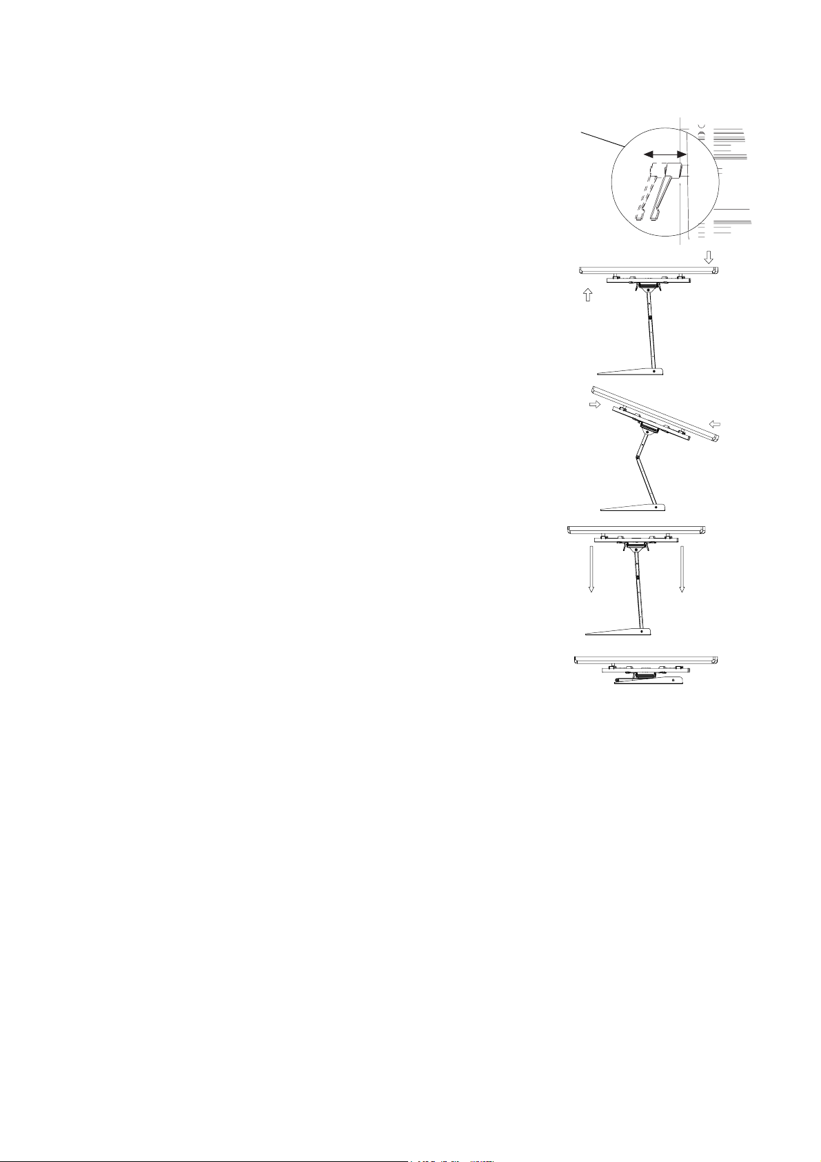
The tilt lever includes a ratchet function, so that it can be lifted and
NB012010
repositioned for the next turn. To operate the ratchet, pull the lever
tilt knob
straight out, rotate it to an unobstructed position, release the lever,
and then turn it in the desired direction. Repeat as necessary until
the tilt tension is set properly (Fig.16).
Swivel- Adjust the flat panel display for off center viewing positions.
Grasp the side edges of the display and then swivel display into its desired
position (Fig.17).
Fig.17
Panning - Positions the flat panel display at an angle to the wall for viewing
from opposite sides of the room.
Grasp the side edges of the display and then swivel and pull the display
into desired position (Fig.18).
Fig.18
Fig.16
Retracting the Flat Panel Display - Positions the display against the wall.
Grasp the side edge of the display, swivel and pull the display into the center
position (Fig.19), and then gently push the display straight back towards the
wall into the retracted position (Fig.20).
Note: Use care when moving the display to ensure that cables do not
become stretched or pinched.
Fig.20
Maintaining the EM-PLA
The arm assembly and wall plate may be cleaned with a soft sponge and mild solution of soap
and water.
Caution: Be sure not to get moisture on the electrical connections or the display.
Fig.19
10
Page 11
mc
GUIDE D'INSTALLATION EM-PLA/PLAB
Support mural universel grand format avec bras d'extension
Caractéristiques
• Conçu pour les écrans plats de 40 po à 58 po
• Peut supporter un poids maximal de 125 lb
• Conforme au normes VESA
• Installation facile par soulèvement et verrouillage
• Range-câbles intégré
• Conforme au normes CUL
Page 12

AVERTISSEMENT
•
LA GARANTIE N'EST VALIDE QUE SI VOUS RESPECTEZ FIDÈLEMENT LES CONSIGNES
•
Si vous ne comprenez pas les consignes ou si vous n'êtes pas certain de pouvoir les respecter de façon
sécuritaire, communiquez avec un technicien qualifié.
•
Une installation inadéquate peut entraîner des dommages et des blessures graves. L'installation du
EM-PLA / EM-PLAB par un technicien qualifié est recommandée.
• Assurez-vous que le mur choisi peut supporter quatre fois le poids combiné de l'équipement monté
de façon sécuritaire, incluant ses accessoires.
• Ce produit ne doit en aucun cas être fixé à des montants de métal.
• Ne dépassez jamais la charge maximale de 150 lb.
• L'aide d'une seconde personne est requise pour plusieurs étapes de l'installation.
• Avant de commencer l'installation, assurez-vous d'avoir toutes les pièces en votre possession.
Téléphonez au 1 866 604-6966 pour obtenir toute pièce manquante.
TABLE DES MATIÈRES
Outils nécessaires à l'installation........................................
Liste des pièces..................................................................
Emplacement du support....................................................
Guide d'installation..............................................................
Préparation du mur.............................................................
Montage au mur .................................................................
Assemblage de la plaque adaptatrice.................................
Configuration de la plaque adaptatrice...............................
Sélection du matériel de montage......................................
Fixation de l'écran...............................................................
Utilisation du range-câbles..................................................
Réglage de l'écran..............................................................
Entretien de l'unité............................................................
3
3
3
4
4
6
7
7
7
8
9
9
10
2
Page 13
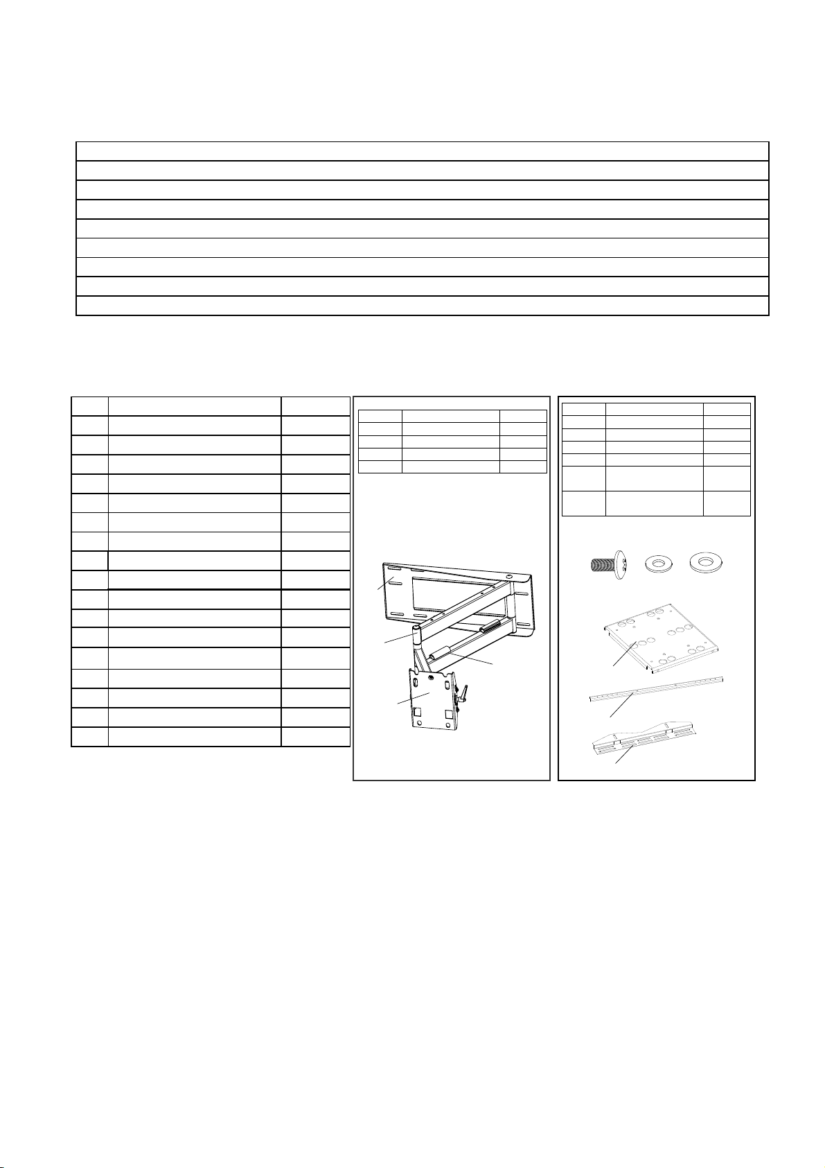
Outils nécessaires à l'installation
Détecteur de montants électronique (installation sur montant de bois seulement)
Perceuse électrique à vitesse variable
Marteau perforateur (installation sur béton seulement)
Forets :
Foret de 1/4" (6 mm) (installation sur montant de bois seulement)
Foret de maçonnerie de 1/2" (13 mm) (installation sur béton seulement)
Marteau (installation sur béton/maçonnerie seulement)
Clé à cliquet avec douille de 11/16" (17 mm)
Tournevis à tête cruciforme
Liste des pièces
Description
ID
Vis Philips M4*35 mm
A
Vis Philips M4*45 mm
B
Vis Philips M5*35 mm
C
Vis Philips M5*45 mm
D
Vis Philips M6*35 mm
E
Vis Philips M6*45 mm
F
Vis Philips M8*35 mm
G
Vis Philips M8*45 mm
H
I
Boulon M8*15 mm
Rondelle métallique
J
K
Clé Allen 5 mm
L
Cale d'espacement 5/8"
Cale d'espacement 3/4"
M
Rondelle circulaire
N
Rondelle à plan carré
O
Tirefonds 3/8"-3 1/2"
P
Q
Ancrage mural
Qté
4
4
4
4
4
4
4
4
4
4
1
4
4
6
4
6
6
ID
a)
Tunnel pour câbles
b)
Tête de montage
c)
d)
a)
d)
c)
Description
Plaque murale
Bras
Qté
1
1
1
1
ID
e)
Panneau d’adaptation
f)
Support d’adaptation
g)
h)
Rondelle métallique
i)
(∅6x∅10x1,2)
Rondelle métallique
j)
(∅6x∅13x1,2)
h)
b)
e)
f)
Description
Barre d’adaptation
Vis M6
i)
Qté
1
2
2
8
4
4
j)
g)
Étape 1 : Choix de l'emplacement pour le montage
Afin d'offrir un maximum de souplesse pour la visualisation, le support EM-PLA offre une grande
latitude d'articulation. Cela permet à l'écran plasma/ACL d'être placé dans presque n'importe quelle
position. Lorsque vous choisissez un emplacement pour le montage, assurez-vous d'avoir
suffisamment d'espace de chaque côté de l'écran pour permettre l'articulation complète du support.
3
Page 14
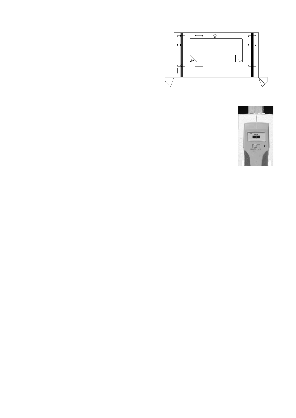
Étape 2 : Guide d'installation
Le guide d'installation est conçu afin de faciliter le montage
de la plaque murale, rendant l'opération plus rapide et plus
précise. Le guide comprend une gouttière recueillant la
poussière, ce qui facilite le nettoyage (Fig. 1).
REMOVE
RETIRER
HAUT
UP
REMOVE
RETIRER
Étape 3 : Préparation du mur
Fig.1
Suivez les consignes adaptées à votre surface de montage:
3a Montant en bois
3b Béton/maçonnerie
3c Bloc de cendre
Étape 3a : Montage sur montant de bois
Le support EM-PLA peut être monté sur deux montants de bois dont la distance
d'un centre à l'autre de ceux-ci se situe entre 15" et 17" (38-43 mm).
À l'aide d'un détecteur de montants électronique (Fig. 2), localisez le centre de
deux montants de bois à l'emplacement de montage désiré. Marquez le centre
des montants directement sur le mur. Reliez les marques avec une ligne
horizontale et trouvez le centre entre ces marques, qui représentera
l'emplacement du centre de l'écran. Assurez-vous de mesurer et de marquer le
centre de cette ligne horizontale.
Placez le guide sur le mur, puis retirez la bande protectrice à l'arrière du guide. Épinglez le
guide sur la marque centrale au mur. À l'aide d'un niveau (à bulle ou à laser), alignez le guide
et appuyez sur la bande adhésive contre le mur afin de maintenir le guide en place.
Remarque : selon la texture du mur, il est possible que vous deviez utiliser un ruban adhésif afin
de maintenir le guide en place.
Fig.2
À l'aide d'un foret de 1/4" (6 mm), percez 6 trous de départ au centre des montants (à travers les
ouvertures pour trous de montage du guide), jusqu'à une profondeur de 3" (76 mm).
Retirez délicatement le guide et jetez-le. Tenez le guide en position verticale afin de ne pas
renverser la poussière récoltée.
4
Page 15
Étape 3b: Montage sur béton/maçonnerie
Hammer
Frappez
Gently
AVERTISSEMENT
• Ne percez JAMAIS dans un joint de mortier!
• Le béton doit être d'une densité minimale de 2000 psi.
La plaque murale peut être montée directement sur les murs de béton/maçonnerie. Retirez la
bande protectrice à l'arrière du guide et placez ce dernier à l'endroit désiré. À l'aide d'un niveau à
bulle/laser, alignez le guide puis appuyez sur la bande adhésive contre le mur afin de maintenir le
guide en place.
Remarque: selon la texture du mur, il est possible que vous deviez utiliser un ruban adhésif afin de
maintenir le guide en place.
À l'aide d'un foret de maçonnerie de 1/2" (13 mm), percez 6 trous de montage d'une profondeur de
3 1/8" (80 mm) dans le mur de béton/maçonnerie. Pour ce faire, servez-vous des ouvertures pour
trous de montage du guide.
Retirez délicatement le guide et jetez-le. Tenez le guide en position verticale afin de ne pas
renverser la poussière récoltée.
légèrement
Push in
Poussez
Fig.3
Insérez les ancrages muraux dans les trous de montage et frappez-les légèrement à l'aide d'un
marteau pour qu'ils soient parfaitement encastrés dans le mur (Fig. 3).
IMPORTANT
Les ancrages de maçonnerie DOIVENT être solidement ancrés dans le béton ou la
maçonnerie. Dans le cas d'un montage sur un mur de maçonnerie recouvert d'une cloison
sèche ou de plâtre, fraisez un trou d'un diamètre plus large à travers la cloison sèche ou le
plâtre jusqu'à la surface de béton/maçonnerie autour du trou de montage, de sorte que
l'ancrage puisse être au même niveau que la surface de béton/maçonnerie.
Étape 3c : Montage sur un bloc de cendre
AVERTISSEMENT
Le bloc de cendre doit être conforme aux spécifications de la norme ASTM C-90.
Effectuez le montage sur la portion solide du bloc, soit environ à 1" des côtés.
Ne percez JAMAIS dans un joint de mortier!
Utilisez un jeu de forets standard réglé à basse vitesse/couple fort. N'utilisez PAS de marteau
perforateur avec un bloc de cendre.
Assurez-vous d'avoir une épaisseur de béton minimale de 1 3/8" dans le trou de montage
avant d'insérer l'ancrage mural.
La plaque murale peut être montée directement sur les murs de blocs de cendre. Retirez la bande
protectrice à l'arrière du guide. À l'aide d'un niveau à bulle, alignez le guideet appuyez sur la bande
adhésive contre le mur afin de maintenir le guide en place.
5
Page 16
Remarque: selon la texture de la surface, il est possible que vous deviez utilisez un ruban adhésif
pour maintenir le guide en place.
À l'aide d'un foret de 1/2" (13 mm), percez 6 trous de montage d'une profondeur de 3 1/8" (80 mm)
dans le mur de blocs de cendre. Pour ce faire, servez-vous des ouvertures pour trous de montage
du guide.
Retirez délicatement le guide et jetez-le. Tenez le guide en position verticale afin de ne pas
renverser la poussière récoltée.
Insérez les ancrages muraux dans les trous de montage et frappez-les légèrement à l'aide d'un
marteau pour qu'ils soient parfaitement encastrés dans le mur (Fig. 3).
IMPORTANT
Les ancrages de maçonnerie DOIVENT être fermement en place dans le mur de
béton ou de maçonnerie. Dans le cas d'un montage sur un mur recouvert d'une
cloison sèche ou de plâtre, fraisez un trou d'un diamètre plus large à travers la cloison
sèche ou le plâtre jusqu'à la surface de béton/maçonnerie autour du trou de montage,
de sorte que l'ancrage soit directement aligné avec le mur de béton ou de
maçonnerie.
Étape 4 : Montage au mur
Retirez le bras de la boîte.
plaque murale
wall plate
Avec l'aide d'une autre personne, tenez le support
en position sur les trous de montage et boulonnez
fermement la plaque murale au mur à l'aide des
rondelles (N) et des tirefonds 3/8"-3 1/2" (P)
fournis. Voir la Fig. 4.
Fig.4
IMPORTANT
Serrez les boulons de sorte que la plaque murale soit fermement fixée au mur, mais NE
les serrez PAS trop fort.
Cela pourrait endommager les boulons et en abîmer le filetage.
Le serrage final des boulons devrait être fait à la main à l'aide d'une clé à cliquet avec
douille.
rondelle
round washer
circulaire,
tirefond de
3/8”-3 1/2” lag bolt
3/8”-3 1/2”
6
Page 17
Étape 5 : Assemblage de la plaque adaptatrice
Fig.6.1
Fig.5.1
Fig.5.2
Étape 7 : Sélection du matériel de montage
Fig.7
7
Fixez le panneau d'adaptation aux barres d'adaptation au
moyen des quatre vis et des quatre rondelles métalliques (Fig.
5.1).
Fixez les supports d'adaptation aux barres d'adaptation au
moyen des quatre vis et des quatre rondelles métalliques (Fig.
5.2).
REMARQUE:afin d'accommoder des écrans de tailles
diverses, les supports peuvent être attachés suivant cinq
positions.
La plaque adaptatrice, de conception universelle, peut être
fixée suivant plusieurs dispositions de montage d'écran,
jusqu'à VESA 400 x 600.
La façon la plus simple de vérifier l'ajustement est de placer la
plaque à l'arrière de l'écran, avec un support de montage
aligné sur une série de trous de montage disposés à la
verticale (Fig. 6.1). Puis, à l'aide du système de centrage
automatique à crémaillère de l'adaptateur, glissez simplement
l'autre support de montage jusqu'à ce qu'il soit aligné sur la
deuxième série de trous de montages verticaux (Fig. 6.1). La
plaque devrait maintenant être centrée horizontalement à
l'arrière de l'écran plat.
Passez à l'étape 7 lorsque les supports sont correctement
alignés avec les trous de montage (Fig. 6.2).
Fig.6.2
Support
d'adaptation
Vis M6
Rondelle
métallique
(¢6*¢13*1.2)
Étape 6 : Configuration de la plaque
adaptatrice
Déterminez les vis de montage requises (A-H) pour votre écran.
Certains écrans plats nécessitent l'utilisation d'une cale
d'espacement. (Fig. 7).
Deux de ces cales d'espacement sont fournies :
- cale d'espacement de 5/8" (16 mm) à embout arrondi (L)
- cale d'espacement de 3/4" (19 mm) en bloc (M)
Rondelle métallique pour
vis M6 (¢6*¢10*1,2)
Barre d’adaptation
Panneau
d’adaptation
Page 18
Ces cales d'espacement peuvent être utilisées seules ou peuvent être superposées pour créer
une cale d'espacement grand format. Les cales d'espacement ont été conçues afin d'être
pressées directement sur le rail de montage pour faciliter la manipulation et comprennent
également deux trous de montages différents pour convenir aux vis de diverses tailles.
De manière générale, la cale d'espacement de 5/8" (L) convient aux écrans plats avec dos
légèrement courbé et/ou avec raccords de montage en retrait. La cale d'espacement de 3/4" (M)
convient aux écrans plats avec dos courbé et les cales d'espacement superposées (L et M)
servent aux écrans plats avec dos très courbé et/ou accessoires protubérants.
Étape 8 : Fixation de l'écran plat
Placez l'adaptateur au dos de l'écran plat. Alignez le rail de montage
gauche avec les trous de montage à l'arrière de l'écran plat. Centrez le rail
verticalement à l'arrière de l'écran et fixez-le en place à l'aide des vis de
montage sélectionnées (A-H), les rondelles à plan carré (O) et les cales
d'espacement (L et M), le cas échéant (Fig. 8).
Remarque: utilisez les ouvertures de montage segmentées des rails pour
centrer l'adaptateur verticalement.
Fig.8
Ensuite, glissez le rail de montage opposé en position, alignez-le avec les trous de montage
et fixez-le à l'aide du matériel de montage.
IMPORTANT
Ne serrez PAS trop les vis de montage, votre écran plat pouvant être
endommagé. N'utilisez JAMAIS un tournevis motorisé pour visser les
vis de montage.
Avec l'aide d'une autre personne, soulevez l'écran avec précaution et fixez-le à la tête de montage.
Serrez les vis (Fig. 8.1).
tête de montage
Boulon M8*15 mm
Rondelle métallique
8,2*1,5*16 mm
Fig.8.1
8
Page 19
Étape 9 : Utilisation du range-câbles
Le support EM-PLA propose un système de rangement du câble
grâce auquel le câble peut être dirigé le long du bras.
Dirigez le câble de l'écran plat à travers l'ouverture du
range-câbles (Fig. 10).
range-câbles
Remarque: pour une performance optimale, dirigez le câble
d'alimentation secteur et les câbles de signaux séparément.
Lorsque tous les câbles sont en place, avancez et reculez
l'écran plat afin de vous assurer que le bras bouge librement,
sans endommager ou tendre les câbles.
câble
Fig.9
Étape 10 : Ajustement de l’écran
Le support EM-PLA peut s'ajuster d'une multitude de façons pour convenir à votre environnement.
Contrôle du niveau: mise à niveau horizontale de l'écran plat.
Saisissez les bords latéraux de l'écran et faites-le pivoter vers le haut ou vers le bas jusqu'à ce qu'il
soit au niveau (Fig. 13).
Fig.13
Ajustement de l'inclinaison: inclinaison vers le haut ou vers le bas de l'écran pour améliorer l'angle
de visualisation.
Saisissez les bords supérieur et inférieur de l'écran et inclinez-le selon la position désirée (Fig. 14).
Fig.14
Pour verrouiller la position, serrez fermement le bouton d'inclinaison (Fig. 15).
REMARQUE: pour les écrans plus lourds, ne déverrouillez jamais le bouton d'inclinaison sans
d'abord supporter entièrement l'écran.
Fig.15
9
Page 20

Le levier d'inclinaison comprend un cliquet, de sorte qu'il puisse
être soulevé et positionné de nouveau lors de l'utilisation
suivante. Pour faire fonctionner le cliquet, tirez et redressez
complètement le levier, faites-le pivoter dans une position libre
de tout obstacle, relâchez le levier et tournez-le dans la direction
désirée. Répéter autant de fois que nécessaire jusqu'à ce que la
tension d'inclinaison soit réglée adéquatement (Fig. 16).
Pivot: ajustement de l'écran plat pour une position de visualisation décentrée. Saisissez les bords latéraux de l'écran et faites
pivoter ce dernier dans la position désirée (Fig. 17).
Fig.17
Panoramique: positionnement de l'écran plat selon un certain
angle avec le mur pour visualisation à partir d'endroits opposés
dans la pièce.
Saisissez les bords latéraux de l'écran, puis faites pivoter et tirez
l'écran dans la position désirée (Fig. 18).
Rentrer l'écran plat: positionnement de l'écran contre le mur.
Fig.16
bouton d'inclinaison
Fig.18
Remarque: prenez garde lors du déplacement de l'écran à ce
que les câbles ne soient pas tendus ou écrasés.
Entretien du support EM-PLA
Le bras et la plaque murale peuvent être nettoyés à l'aide d'une
éponge non abrasive et d'une solution douce faite d'eau et de
savon.
Attention: assurez-vous de ne pas mouiller les connexions
électriques de l'écran.
Fig.19
Fig.20
10
 Loading...