

Page 1

All support and warranty is handled by TOLIS Group, Inc.
Warranties are provided by TOLIS Group, Inc. and can be found at:
www.tolisgroup.com/documentation.html
For warranty, RMA assistance, or technical support help, please visit:
www.tolisgroup.com/support.html
Page 2
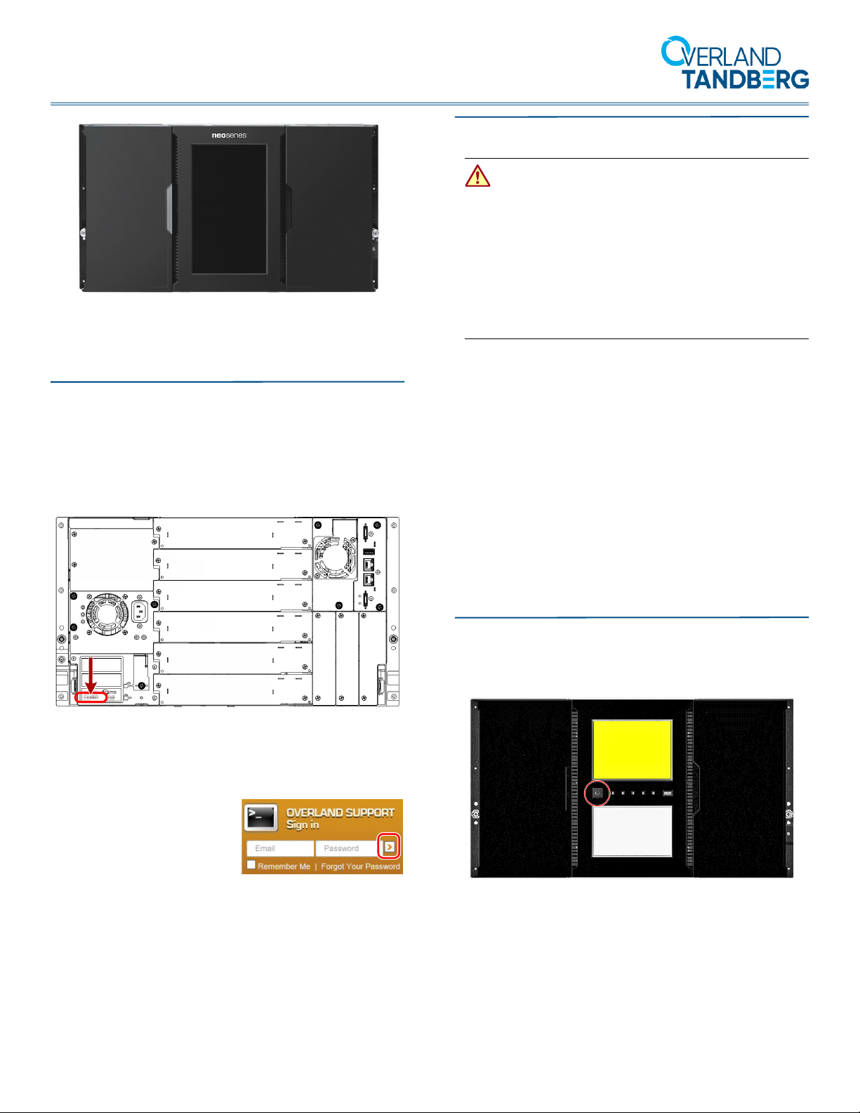
NEOxl 80 6U Expansion Module
*10400898*
10400898
Quick Start Guide
This document describes how to add an optional Expansion
Module to a NEOxl 80 6U tape library system.
Step 1
It is essential that you activate your warranty. Technical
and warranty support are not available until the warranty
is active.
The serial number is located at the rear of the module on the
bottom left cover.
Step 2
WARNING: Due to the weight of the module, it is
recommended that at least two people be used to lift the
module out of the box to prevent injury.
WARNUNG: Um Verletzungen zu vermeiden, empfehlen
wir aufgrund des Gewichts des Moduls, dass mindestens
zwei Personen das Modul aus der Verpackung heben.
AVERTISSEMENT: En raison du poids du module, il est
recommande d'utiliser deux personnes au moins pour
soulever l'module hors de la boîte pour éviter les
blessures.
NOTE: If the temperature in the room where the module will be
installed varies by 15º C (30º F) from the room where the boxed
module was stored, allow it to acclimate to the surrounding
environment for at least 12 hours before unpacking it.
Unpack the Module
1. Using two people, remove the module from its box and
set it on a secure surface.
2. Remove and save the packaging materials and tape
from the Expansion Module.
Module Registration
For an existing customer:
1. Go to http://support.overlandstorage.com/ support page.
2. Enter your e-mail
address and password
in the appropriate fields,
and then press Enter or
click the right arrow (
3. At the Support Home page, click Register New.
4. Enter the requested information and click Submit.
Your warranty certificate will be emailed to you. Follow
the instructions in the email to complete the process.
For a new customer:
1. Go to the New User Registration page and follow the
instructions.
2. You’ll receive a confirmation e-mail from Overland with
instructions on how to complete the process.
>).
Tools Needed
You will need a small flat head or Torx screwdriver and a #2
Phillips screwdriver.
Step 3
Power Off Library
If still running, power off the tape library from the Base
Module front panel by pressing and holding down the power
button for three (3) seconds.
NOTE: If the library does not perform a soft shutdown, press
and hold the power button for 10 seconds.
Verify that the Robotic Assembly is in its parked position
and that all host processes are idle.
10400898 ©2019 Overland-Tandberg Page 1 of 5
Page 3

NEOxl 80 6U Expansion Module Quick Start Guide
Reserve 6U (10.5 in.)
&
Each EIA unit (1U) starts at a
narrow gap and has three holes
and two wide gaps above it
Wide Gaps within the EIA unit
Narrow Gaps between EIA units
Mark
Here
Prepare the Modules
Depending on the new Expansion Module’s location, transfer
either the top or bottom module cover from the last module
in that location to the new Expansion Module.
• If you are installing the Expansion Module below the
module stack, move the bottom module’s cover to the
Expansion Module.
• If you are installing the Expansion Module above the
module stack, move the top module’s cover to the
Expansion Module.
IMPORTANT: A NEOxl tape library modular system can
support up to six Expansion Modules, three above and
three below. If you have not yet determined the architecture of
your configuration, refer to Chapter 1, “Supported
Configurations,” in the NEOxl 80 Tape Library Administrator’s
Guide for details.
1. Using the mechanical lifter, remove the existing
module from which you are moving the cover plate.
2. Place the module you removed on a secure work table.
If you are removing the bottom cover, gently turn the
module over so you can access the bottom.
3. Place the new Expansion Module on the work table
next to the module you removed.
If you are adding the bottom cover, gently turn the
module over so you can access the bottom.
Step 4
WARNING: To reduce the risk of electric shock or
damage to equipment, always remove any power cords
while working with the unit.
WARNUNG: Um das Risiko eines elektrischen Schlags
oder Schäden am Gerät zu vermeiden, ziehen Sie stets
den Netzstecker, bevor Sie an der Einheit arbeiten.
AVERTISSEMENT: Pour réduire le risque de choc
électrique ou endommagement de l'équipement, retirez
toujours les cordons électriques en travaillant avec
l'appareil.
The NEOxl 80 6U tape libraries are expandable and accept
add-on components to enhance performance:
• The Expansion Module comes without tape drives. Tape
drives are always installed in the module from the
bottom bay up.
• A second Power Supply Unit can be added to Expansion
Module for redundancy.
IMPORTANT: Follow the component instructions included
with each item to be sure they are installed correctly.
Step 5
A NEOxl 80 6U Expansion Module comes with a rack kit for
easy installation and securing of the module into a 19-inch
(EIA-310) rack.
4. Insert a small flathead screwdriver or Torx screwdriver
into the front hole (1) to retract the spring lock, slide
the cover (2) forward until it reaches the tool, remove
the tool, and then continue sliding the cover to the front
of the module until all the tabs are released.
5. Remove the cover (3) from the existing module.
6. At the Expansion Module, install the cover.
Align all cover tabs with the slots, gently push it down,
and then slide the cover towards the rear until the
spring lock engages.
7. If the modules are upside down, gently turn them both
back over.
8. Using the mechanical lifter, reinstall the existing
module back into the rack in its same location.
IMPORTANT: Two-post telco-style or other racks less than
29 inches in depth will NOT support these modules.
Install the Rack Rails
1. Determine the location in your rack for your Expansion
Module to be installed and, using a pencil, mark the
location on each vertical rail in your rack.
10400898 ©2019 Overland-Tandberg Page 2 of 5
Page 4
NEOxl 80 6U Expansion Module Quick Start Guide
It is recommended to start at the lowest position of the
rack for stability. The bottom mark should be at the
lowest narrow gap in that position.
NOTE: The library requires 6U (10.5 in.) of rack space.
2. From the front of the rack, insert the rack rails into
the back and then front vertical supports.
a. Position a rail according to the orientation
information stamped on the rail.
b. Rotate the front of the rail up while inserting the
rear rail hanger into the rear vertical support, and
then lower the front of the rail until it is nearly level.
c. Extend the front of the rail until the hangers come
through the holes in the vertical support and the
retention spring snaps into place.
d. Repeat Steps a–c the other rail.
WARNUNG: Um Verletzungen zu vermeiden, empfehlen
wir zur Rack-Installation oder -Deinstallation die Nutzung
einer mechanischen Hebehilfe (oder mindestens zwei
Personen). Seien Sie vorsichtig bei der Rack-Installation
oder -Entnahme, um ein versehentliches Kippen des
Racks zu vermeiden und das Rack nicht zu beschädigen
bzw. sich selbst zu verletzen.
AVERTISSEMENT: Afin d’éviter des blessures pendant
l’installation, il est recommande d’utiliser un montecharge (ou au moins deux personnes) pour élever ou
aligner l’module. Faites attention lorsque vous insérez ou
retirez l’module d’un support, pour empêcher le
déversement accidentel de la crémaillère causant des
dommages et des blessures.
1. Extend the middle rails until they lock into place.
2. Move the sliding assembly to the front of the middle
rails.
3. Using the mechanical lifter, position the Expansion
Module in front of the rack, aligned with the extended
rails.
4. Slide the module onto the middle rails (1) and into the
rack until it stops (2).
5. Secure it to the rack with the captive screws on the
front of the module.
NOTE: The rails must be fastened with the bottom of the
each rail parallel to floor and at the same level.
3. On the front of both rails in a square-hole lock, install a
clip nut above the mounting bracket as shown (1).
4. For increased stability, install the supplied retention
inserts (3).
Insert the Module in the Rack
WARNING: To avoid injury, it is recommended that a
mechanical lifter (or at least two people) be used for rack
installation or removal. Use care during rack installation
or removal to avoid accidentally tilting or tipping the rack,
causing damage or personal injury.
Aligning and Connecting Modules
Aligning the modules ensures that the robotics can move
freely between the modules. The library will not operate
unless the alignment mechanisms are in the locked position.
1. From the front of the library, loosen the thumbscrews
on each of the modules two full turns.
2. From the back of the library, starting with the bottom
pair of modules, align each module with the module
below. Repeat for each pair of modules.
10400898 ©2019 Overland-Tandberg Page 3 of 5
Page 5

NEOxl 80 6U Expansion Module Quick Start Guide
SAS Tape Drive
FC Tape Drive
Expansion
Module
Base
Library
Expansion
Module
Expansion
Cables
a. Loosen the thumbscrew (1) on the module
alignment mechanism.
b. Lower the alignment mechanism (2).
If you encounter resistance, adjust the position of the
upper module so the pin in the alignment mechanism
moves into the hole in the lower module.
c. With the alignment mechanism in the locked
position, tighten the thumbscrew (3).
3. Verify that the lowest module in the library has its
alignment mechanism secured in the unlocked
position with the thumbscrew.
4. From the front of the library, use your fingers to tighten
the thumbscrews on each of the modules to secure the
modules to the rack.
Step 6
WARNING: To reduce the risk of electric shock or
damage to equipment, always remove any power cords
while working with the unit.
WARNUNG: Um das Risiko eines elektrischen Schlags
oder Schäden am Gerät zu vermeiden, ziehen Sie stets
den Netzstecker, bevor Sie an der Einheit arbeiten.
AVERTISSEMENT: Pour réduire le risque de choc
électrique ou endommagement de l'équipement, retirez
toujours les cordons électriques en travaillant avec
l'appareil.
2. Attach the other end of the host interface cable as
follows:
• For a SAS expansion, connect the host interface
cable to the host HBA.
• For a Fibre Channel expansion, connect the fibre
cable to the host or switch.
Expansion Cable Attachment
From the back of the library connect the new Expansion
Module to the existing adjacent module using the expansion
interconnect cable.
• For a new module at the top of the library stack, use
the lower port of the new Expansion Module and
connect to the upper port of the adjacent module.
• For a new module at the bottom of the library stack,
use the upper port of the new Expansion Module and
connect to the lower port of the adjacent module.
The Expansion Module comes without tape drives. Tape
drives are always installed in the module from the bottom
bay up.
IMPORTANT: Follow the component instructions included
with the drives to be sure they are installed correctly.
Step 7
All cabling, power connections, and cooling are located on the
rear panel.
Drive Cable Attachment
If tape drives are installed in the Expansion Module:
1. Attach one end of the host interface cable to the
expansion:
• For a Serial Attached SCSI (SAS) connected
expansion, attach one end of the SAS cable to
Port A (left) SAS HBA on the SAS drive.
• For a Fibre Channel (FC) expansion, attach one end
of the fibre cable to Port A (top) connector on the
FC drive, removing the cap if necessary.
Power Cord Attachment
Plug the power cords into the power connectors on the new
Expansion Module and into power outlets.
NOTE: The expansion has dual redundant power supplies. To
increase redundancy, plug each power cord into a different AC
power circuit.
10400898 ©2019 Overland-Tandberg Page 4 of 5
Page 6

NEOxl 80 6U Expansion Module Quick Start Guide
Step 8
Power on the library from the Base Module front panel by
pressing and holding down the power button for three (3)
seconds until the green light on the front panel illuminates
Ready
indicating the status is
.
Verifying the Installation and Configuration
Check the following:
• From the OCP or RMI, verify that the new Expansion
Module is visible.
• Check the library configuration settings related to the
additional storage slots, mailslots, and tape drives.
Update if necessary.
Step 9
Step 10
For further information regarding your product, check out
the following links.
User Guide
For detailed information on configuring your
NEOxl 80 6U, refer to the NEOxl 80 Tape
Library Administrator’s Guide available
online under Resources at:
http://docs.overlandstorage.com/neo
More information can be accessed from the OverlandTandberg Knowledge Base:
https://www.overlandtandberg.com/knowledgebase/
Warranty/Technical Support
For warranty and general technical support
information, see our Contact Us page:
http://www.overlandstorage.com/company/
contact-us/index.aspx
For information on contacting Overland-Tandberg technical
support, go to:
http://docs.overlandstorage.com/support
Confirm Your Library Firmware Version
The Expansion Module operates using the existing library
firmware. It is recommended that you always update the
library to the latest firmware version:
1. At the Startup Screen, make a note of the firmware
version.
2. Go to the Overland-Tandberg
site:
http://docs.overlandstorage.com/neo
3. Under Downloads/NEO Series Firmware, click the link
for the library.
4. At the FTP site, if newer firmware is shown, download
the firmware and Release Notes.
5. Update the firmware using the NEOxl 80 Tape Library
Administrator’s Guide.
Downloads and Resources
Confirm Your Tape Drive Firmware
Refer to the installation instructions and warnings that are
packaged with your tape drive to determine if the firmware
is current or needs to be updated.
If you determine that the firmware should be updated, follow
the steps detailed in the included tape drive instructions.
http://support.overlandstorage.com
Overland Storage and Tandberg Data are wholly-owned subsidiaries of Sphere 3D Corp. You can get additional technical
support at the Overland Storage Support web page, or by using the information found on the Contact Us page on our web site.
10400898 ©2019 Overland-Tandberg Page 5 of 5
 Loading...