

Page 1
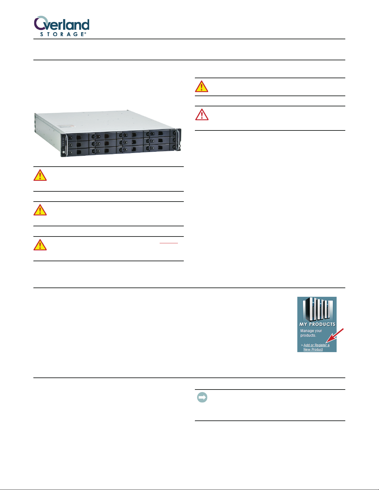
ULTAMUS™ RAID 1200\1200x
Quick Start Guide
This document describes how to unpack and install an
ULTAMUS RAID 1200 Storage Array or 1200x Expansion
Array into a standard RETMA 19" rack. Each appliance
has a 2U form factor.
WARNING: Unplug the AC power and network
connections if you think that the unit has become
damaged in any way, or before you move it.
WARNING: Use care inserting or removing an
ULTAMUS array into or out of a rack to prevent tipping
of the unit causing damage or personal injury.
WARNING: Due to the weight of the array, it is strongly
recommended that at least two people be used to lift
the unit out of the box to prevent injury.
WARNING: Do not remove covers from the Power
Supply module. Danger of electric shock inside.
CAUTION: All plug-in modules and blank plates are part
of the enclosure and the system must not be run without
all modules in place.
European Regulations
This equipment complies with European Regulations EN
55022 Class A: Limits and Methods of Measurement of
Radio Disturbance Characteristics of Information
Technology Equipment and EN50082-1: Genetic
Immunity.
USA Federal Communications Commission
This equipment has been tested and found to comply with
the limits for a Class A digital device, pursuant to part 15
of the Federal Communications Commission (FCC) rules.
Electrostatic Discharge Information
A discharge of static electricity can damage micro-circuitry
or static-sensitive devices. To help prevent Electrostatic
Discharge (ESD), observe standard ESD precautions.
1. Activate Your Warranty
Before installing your new array, it is essential that you
activate your ULTAMUS warranty. Technical and
warranty support are not available until this is done.
1. Go to the Overland Technical Support website at:
http://support.overlandstorage.com/
2. Using the MEMBER LOGIN E-mail and Password
fields, log in to the site.
NOTE:
click the SIGN UP NOW button and
follow the instructions to become a
member. It’s free!
3. Under MY PRODUCTS, click Add
or Register a New Product and
follow the on-screen instructions.
2. Preparation of Site and Host Server
Before you begin, make sure that the site where you
intend to use your storage system has the following:
• Host computer with a standard Fibre Channel (FC)
HBA with the latest BIOS and drivers. Follow the
instructions provided with your host bus adapter.
Install the HBA and its driver software, if necessary.
• Standard AC power from an independent source or a
rack power distribution unit with a UPS.
click the “ULTAMUS RAID 1200 Driver for Windows” link, and
follow the on-screen instructions.
If you are not yet a member,
IMPORTANT: For Microsoft Windows Servers—Insert the
ULTAMUS RAID 1200 Software and Documentation CD,
Part Number 10400049-102 07/2007 ©2007 Overland Storage, Inc. W Page 1 of 4
Page 2
3. Box Contents
The contents of the shipping box are:
• One ULTAMUS RAID 1200 head unit or 1200x
expansion array
• Accessory Kit
• This quick start guide
The Accessory Kit contains:
• Two AC power cables
• Rack-mounting rail kit with hardware
4. Mounting the Array in a Rack
NOTE: The rack kits may vary depending on the model.
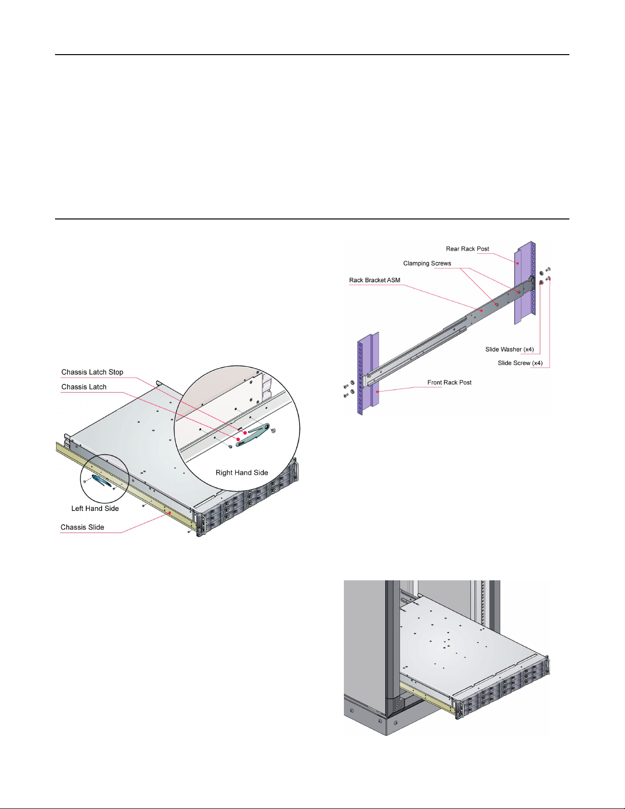
1. Attach left and right chassis slides to the side of the
enclosure using 8 M3x4 buttonhead screws.
2. Assemble the left and right chassis latches using the
special chassis latch screws (Figure 1).
Ensure each latch is correctly oriented, with the spring
arm located against its stop. On the right side, the
spring arm should be toward the top, on the left side it
should be toward the bottom.
• ULTAMUS Software and Documentation CD
Head unit only:
• Serial cable for service
• Four SFP modules
• Drive lock key (torx driver)
Expansion array only:
• Two SAS cables
Figure 1. Attaching Chassis Slides and Latches
3. Attach the left bracket to the rack (Figure 2):
a. Place the location pin at the rear end of the rail into
rear rack post.
b. Extend the rail to fit between the front and rear rack
posts.
c. Attach the rail to both front and rear rack posts
using supplied screws and washers.
The screws should be left loose enough to allow
sideways movement of the rails.
d. Tighten the two clamping screws on the rail.
4. Repeat Step 3 for the right bracket.
Figure 2. Securing Brackets to Rack (Left Side Shown)
5. Mount the chassis into the rack as follows (Figure 3):
a. Lift chassis and align with rack rails.
b. Carefully insert the chassis slides into the rack rails
and push fully home.
c. Tighten rear screws.
d. Withdraw the chassis until it reaches the hard stops,
approximately 400mm (15.75 in.).
e. Tighten front screws.
f. Return chassis to the fully home position and secure
to rack using captive fasteners on front flanges.
Figure 3. Mounting the Array in a Rack
Part Number 10400049-102 07/2007 ©2007 Overland Storage, Inc. W Page 2 of 4
Page 3

5. Data Connections
Each RAID Controller module has two FC SFP interfaces
and can be connected to up to two independent Host Bus
adapters or switch ports. A typical configuration is shown
below (Figure 4).
four expansion arrays can be connected to the ULTAMUS
RAID 1200 storage appliance. A typical configuration is
shown in Figure 5. Refer to the ULTAMUS RAID 1200
Setup Guide for more options.
NOTE:
The Expansion port connects to the Host port on the next
expansion chassis in a multiple chassis configuration.
ULTAMUS RAID 1200
ULTAMUS RAID 1200X
ULTAMUS RAID 1200X
Figure 4. Dual Host, Single HBA, and Single Controller
NOTE:
See the ULTAMUS RAID 1200 Setup Guide for more
configuration options.
Additional ULTAMUS RAID 1200x expansion arrays can
be connected to the main appliance. Multiple arrays are
connected together using SAS patch cables. A maximum of
6. Power On
WARNING: Before applying power, carry out the
grounding checks.
1. Lift the bale up (Figure 6), insert the power cord, and
place the bale over and onto the cord.
ULTAMUS RAID 1200X
Figure 5. Connecting The Expansion Enclosure
2. Run the power cords over to the Power Distribution
Units (PDU) in the rack or another power source
(Figure 7).
Power Supply Modules (PSU)
Rack Power Distribution Units (PDU)
Figure 7. Connecting the AC Power
3. Power on the storage system by connecting cables to
external PDU or powering on the PDU.
4. Power the host system.
Figure 6. Cable Strain Relief Bale Locations
Part Number 10400049-102 07/2007 ©2007 Overland Storage, Inc. W Page 3 of 4
Page 4

7. Operator/Control Panel
The ULTAMUS RAID 1200 front panel incorporates an
Operator’s (OPS) Panel with four LEDs (Figure 8). The
OPS Panel provides a high-level indication of the
operation of the appliance.
NOTE:
The OPS Panel is an integral part of the chassis assembly
and can only be replaced with a replacement chassis. Chassis
replacement should only be performed by trained personnel.
Table 1: Operator’s Panel LED Definitions
OPS Panel LEDs
Figure 8. Operator’s Panel LEDs
PowerOnSystem
Fault
ON ON ON ON
Logical
Fault
Box
Identify
Other LEDs or Alarms State Description
Single beep, two double beeps Power-On Self Test
ON OFF
ON ON
ON ON
ON ON
PSU Fault LED or Cooling Fan
Module Fault LED
RAID Controller Fault LED on the
specific controller
Drive Fault LED Drive failure has occurred causing loss of availability or
ON ON
ON
8. Additional Information
The ULTAMUS RAID 1200 appliance is preconfigured
with default IP addresses:
• 10.1.1.5 for the lower RAID Controller (Controller 0)
• 10.1.1.6 for the upper RAID Controller (Controller 1)
• 10.1.1.7 if an error is detected
• 255.0.0.0 for the subnet mask
IMPORTANT: Do not connect the unit to a DHCP network
before establishing the IP addresses with the host.
Power On, all functions good
Any PSU Fault, Cooling Fan Module Fault, or Over/
Under Temperature Condition
A RAID Controller Fault
redundancy
Array is performing background function such as a
parity check, initialization, or expansion
Chassis identification mode. When illuminated it
identifies the specific chassis
Launching ULTAMUS RAID manager
1. In your Web browser on the management system, enter
the applicable IP address to access the array, in the
following format (example):
http://10.1.1.5:9292
2. Use the following default login (case-sensitive):
Logon: admin
Password: password
3. Begin the configuration process.
For detailed instructions on how to connect the ULTAMUS RAID 1200 Storage Appliance to a network, and all other
appliance configuration information, see the ULTAMUS RAID 1200 Setup Guide found on the ULTAMUS RAID 1200
Software and Documentation CD.
Additional Help
You can get additional technical support on the Internet at http://support.overlandstorage.com, or call
1-877-654-3429 (toll-free U.S. & Canada), +44 (0) 118-9898050 (Europe), or +1 (858) 571-5555 Option 5 (International).
All information contained in or disclosed by this document is considered proprietary by Overland Storage. By accepting this material, the recipient agrees that this material and the information contained therein are held in confidence and in trust and will not be
used, reproduced in whole or in part, nor its contents revealed t o others, except to meet the purpose for which it was delivered. It is unders tood that no right is conveyed to reproduce or have reproduced any item herei n disclosed without express permission from
Overland Storage. Overland Storage provides this document as is, without warranty of any kind, either expressed or implied, including, but not limited to, the implied warranties of merchantability and fitness for a particular purpose. Overland Storage may make
improvements or changes in the product(s) or program(s) described in this document at any time. These changes will be incorporated in new editions of this publication.
Overland Storage assumes no responsibility for the accuracy, completeness, sufficiency, or usefulness of this document, nor for any problem that might arise from the use of the information in this document.
Part Number 10400049-102 07/2007 ©2007 Overland Storage, Inc. W Page 4 of 4
 Loading...