

Page 1

Overland
Storage
®
ULTAMUS
RAID 1200
Hardware Setup Guide
January 2008
10400165-101
Page 2

ULTAMUS RAID 1200 User Guide
OVERLAND STORAGE END USER LICENSE AGREEMENT (“EULA”)
IMPORTANT NOTICE - PLEASE READ THIS END USER SOFTWARE LICENSE AGREEMENT (“EULA”) CAREFULLY BEFORE USING THE
SOFTWARE CONTAINED IN THIS EQUIPMENT OR USING THIS EQUIPMENT IN ANY MANNER.
BY USING THE EQUIPMENT THAT CONTAINS THIS SOFTWARE, YOU ARE CONSENTING TO BE BOUND BY THIS AGREEMENT. IF
YOU DO NOT AGREE TO ALL OF THE TERMS OF THIS END USER AGREEMENT, PROMPTLY RETURN AND DO NOT USE THE
EQUIPMENT AND THE SOFTWARE.
1. Single User License. Subject to the terms and conditions of this EULA, Overland Storage, Inc. (“Overland”) grants to you (“Customer”) a nonexclusive, non-transferable license to use (a) Overland software which provides the basic operating environment for Overland equipment and
whether pre-installed on, embedded in or provided with Overland equipment, and (b) the specific Overland program modules or features which
have been enabled by security keys supplied by Overland and for which Customer had paid any applicable license fees (collectively, the “Software”),
both of the foregoing in object code form only: (i) solely as pre-installed, embedded in or provided with Overland equipment owned or leased by
Customer; and (ii) for key-enabled Software corresponding to the security key(s) supplied by Overland and for the license fees paid by Customer.
2. Limitations. Except as otherwise expressly provided under this EULA, Customer will have no right, and Customer will not:
(i) make error corrections to or otherwise modify or adapt the Software nor create derivative works based upon the Software, or to permit third
parties to do the same;
(ii) copy, in whole or in part, decompile, translate, reverse engineer, disassemble or otherwise reduce the Software to human-readable form; or
(iii) remove the Software from the equipment in which it is embedded.
3. Upgrades and Additional Copies. For purposes of this EULA, “Software” will also include (and the terms and conditions of this EULA will
apply to) any upgrades, updates, bug fixes or modified versions (collectively, “Upgrades”) or backup copies of the Software licensed or provided to
Customer by Overland or an authorized distributor for which Customer had paid the applicable license fees and holds the corresponding software
keys. Notwithstanding the foregoing, Overland will have no obligation to provide any Upgrades under this EULA. If Upgrades are provided, (i)
Customer has no license or right to use any such additional copies or Upgrades unless Customer, at the time of acquiring such copy or Upgrade,
already holds a valid license and the corresponding security keys to the original Software; and (ii) use of the Upgrades is limited to Overland
equipment for which Customer is the original End-User purchase or lessee.
4. U.S. Government Restriction Rights. The Software was developed at private expense and is provided with “RESTRICTED RIGHTS” as set
forth in this License Agreement. Use, duplication or disclosure by the United States government is subject to restrictions as set forth in FAR
52.227-14 and DFARS 252.227-7013 et seq., or its successors. The use of this Software constitutes acknowledgement of Company’s and its licensors’
rights in the Software.
5. Notices of Proprietary Rights. Customer will maintain and reproduce all trademark, copyright, patent, and notices of other proprietary
rights on all copies, in any form, of the Software in the same form and manner that such trademark, copyright, patent, and notices of other rights
are included on the Software. Except as expressly authorized in this EULA, Customer will not make any copies or duplicates of any Software
without the prior written permission of Overland.
6. Proprietary Rights.
hereunder. Any references to terms in connection with the foregoing, such as “sale”, “purchase” or “sell” will be interpreted as licensed rights
granted on a non-exclusive basis hereunder and as otherwise provided in this EULA. Overland’s rights under this Section will include, but not be
limited to: (i) all copies of the Software, in whole and in part; and (ii) all intellectual property rights in the Software.
7. Confidential Information. Customer will not disclose or, except as expressly permitted in this EULA, use any Software or other technical
information disclosed to Customer by Overland (“Confidential Information”). Customer will take all reasonable measures to maintain the
confidentiality of all Confidential Information in Customer’s possession or control, which will in no event be less than the measures Customer uses
to maintain the confidentiality of Customer’s own information of equal importance. Confidential Information will not include information that: (i)
is in or enters the public domain without breach of this EULA; (ii) Customer receives from a third party without restriction on disclosure and
without breach of a nondisclosure obligation; or (iii) Customer develops independently, which Customer can prove with written evidence.
The Confidential Information is a trade secret of Overland, the disclosure of which would cause substantial harm to Overland that could not be
remedied by the payment of damages alone. Accordingly, Overland will be entitled to preliminary and permanent injunctive relief and other
equitable relief for any breach of this Section.
8. Limited Software Warranty. Overland warrants that the Software will substantially conform to its published specifications for a period of 90
days from the later of receipt of the equipment containing the Software or receipt of access to the Software. This limited warranty extends only to
Customer as the original licensee. Provided that (a) Customer has notified Overland of such substantial non-conformance during the applicable
warranty period, and (b) Overland has confirmed such Software to be substantially non-conforming, as Customer’s sole and exclusive remedy and
Overland’s and its suppliers’ entire liability under this limited warranty, Overland will, at its option, repair, replace, or refund the Software
pursuant to Overland’s then-current warranty policy.
Except as expressly provided in this EULA, the Software is provided “AS IS” without warranty of any kind. Overland does not warrant that the
Software is error free or that Customer will be able to operate the Software without problems or interruptions. Overland reserves the right to
charge additional fees for repairs or replacements performed outside of the 90-day limited warranty period.
This warranty does not apply if the Software or the Overland equipment in which the Software is embedded (i) is licensed for beta, evaluation,
testing or demonstration purposes for which Overland does not receive a license fee, (ii) has been altered, except by Overland, (iii) has not been
installed, operated, repaired, or maintained in accordance with instructions supplied by Overland, (iv) has been subjected to abnormal physical or
electrical stress or to misuse, negligence, or accident, or (v) is used in ultra-hazardous activities.
9. Disclaimer. EXCEPT AS SPECIFIED IN THIS EULA, ALL EXPRESS OR IMPLIED CONDITIONS, REPRESENTATIONS, AND
WARRANTIES INCLUDING, WITHOUT LIMITATION, ANY IMPLIED WARRANTY OR CONDITION OF MERCHANTABILITY, FITNESS
FOR A PARTICULAR PURPOSE, NON-INFRINGEMENT, SATISFACTORY QUALITY OR ARISING FROM A COURSE OF DEALING,
USAGE, OR TRADE PRACTICE, ARE HEREBY EXCLUDED TO THE EXTENT ALLOWED BY APPLICABLE LAW. IN NO EVENT WILL
OVERLAND OR ITS SUPPLIERS BE LIABLE FOR ANY LOST REVENUE, PROFIT, OR DATA, OR FOR SPECIAL, INDIRECT,
CONSEQUENTIAL, INCIDENTAL, OR PUNITIVE DAMAGES HOWEVER CAUSED AND REGARDLESS OF THE THEORY OF LIABILITY
ARISING OUT OF THE USE OF OR INABILITY TO USE THE SOFTWARE EVEN IF OVERLAND OR ITS SUPPLIERS HAVE BEEN ADVISED
OF THE POSSIBILITY OF SUCH DAMAGES. IN NO EVENT WILL OVERLAND’S TOTAL LIABILITY TO CUSTOMER, WHETHER IN
CONTRACT, TORT (INCLUDING NEGLIGENCE), OR OTHERWISE, EXCEED THE PRICE PAID BY CUSTOMER. THE FOREGOING
LIMITATIONS WILL APPLY EVEN IF THE ABOVE-STATED WARRANTY FAILS OF ITS ESSENTIAL PURPOSE.
Each party recognizes and agrees that the warranty disclaimers and liability and remedy limitations in this EULA are material bargained for
bas es of t his EULA and that th ey ha ve be en ta ken into accoun t and reflected in determining the consideration to be given by each party under this
EULA and in the decision by each party to enter into this EULA.
10. Term and Termination. This EULA is effective until terminated. Customer’s license rights under this EULA will terminate immediately
without notice from Overland if Customer fails to comply with any provision of this EULA. Upon termination, Customer must destroy all copies of
Software and the corresponding security keys in its possession or control.
The Software is and will remain the sole and exclusive property of Overland. Software is licensed, not sold, by Overland
10400165-101 01/2008 ©2007-2008 Overland Storage, Inc. W ii
Page 3

ULTAMUS RAID 1200 User Guide
11. Compliance With Law. Each party will comply with all applicable laws, rules and regulations in connection with its activities under this
EULA. Without limiting the foregoing, the Software, including technical data, is subject to United States export control laws, including the United
States Export Administration Act and its associated regulations, and may be subject to export or import regulations in other countries. Customer
will comply strictly with all such regulations and acknowledges that Customer has the responsibility to obtain licenses to export, re-export, or
import the Software.
12. Restricted Rights. The Software will be classified as “commercial computer software” as defined in the applicable provisions of the Federal
Acquisition Regulation (the “FAR”) and supplements thereto, including the Department of Defense (DoD) FAR Supplement (the “DFARS”). The
parties acknowledge that the Software was developed entirely at private expense and that no part of the Software was first produced in the
performance of a Government contract. If the Software is supplied for use by DoD, the Software is delivered subject to the terms of this EULA and
either (i) in accordance with DFARS 227.702-1(a) and 227.7202-3(a), or (ii) with restricted rights in accordance with DFARS 252.227-7013(c)(1)(ii)
(OCT 1988), as applicable. If the Software is supplied for use by a Federal agency other than DoD, the Software is restricted computer software
delivered subject to the terms of this EULA and (i) FAR 12.212(a); (ii) FAR 52.227-19; or (iii) FAR 52.227-14 (ALT III), as applicable.
13. Third Party Software. Third party suppliers of materials integrated with the Overland equipment disclaim all implied warranties, including
the implied warranties of merchantability and fitness for a particular purpose. The collective liabilities of the seller/licensor and its third party
suppliers are subject to the limitation of liabilities described in this agreement. The third party supplier is an intended beneficiary of this
limitation.” Third party suppliers disclaim all liability for consequential or other indirect damages or for loss of or damage to data or records.
14. General. This EULA will bind and inure to the benefit of each party’s successors and assigns, provided that Customer may not assign or
transfer this EULA, in whole or in part, without Overland’s written consent.
This EULA will be governed by and construed in accordance with the laws of the State of California, United States of America, as if performed
wholly within the state and without giving effect to the principles of conflict of law.
No failure of either party to exercise or enforce any of its rights under this EULA will act as a waiver of such rights.
Any waivers or amendments will be effective only if made in writing by non-preprinted agreements clearly understood by both parties to be an
amendment or waiver and signed by a representative of the respective parties authorized to bind the parties.
If any portion hereof is found to be void or unenforceable, the remaining provisions of this EULA will remain in full force and effect.
This EULA is the complete and exclusive agreement between the parties with respect to the subject matter hereof, superseding and replacing any
and all prior agreements, communications, and understandings (both written and oral) regarding such subject matter.
Any notice, report, approval or consent required or permitted hereunder will be in writing and will be deemed to have been duly given if delivered
personally or mailed by first-class, registered or certified US mail, postage prepaid to the respective addresses of the parties. The prevailing party
in any action to enforce this EULA will be entitled to recover costs and expenses including, without limitation, reasonable attorneys’ fees.
A material breach of this EULA adversely affecting Overland’s proprietary rights in the Software would cause irreparable injury to Overland for
which monetary damages would not be an adequate remedy and that Overland will be entitled to equitable relief in addition to any remedies it
may have hereunder or at law.
©2007, ©2008 Overland Storage, Inc. All rights reserved.
Overland®, Overland Storage®, LoaderXpress®, Multi-SitePAC®, NEO SERIES®, PowerLoader®, Protection OS®, REO®, REO SERIES®,
ULTAMUS®, VR2®, WebTLC®, and XchangeNOW® are registered trademarks of Overland Storage, Inc.
ARCvault™, NEO™, Simply Protected™, Simply Protected Storage™, SnapWrite™, and ULTAMUS SERIES™ are trademarks of Overland
Storage, Inc.
All other brand names or trademarks are the property of their respective owners.
The names of companies and individuals used in examples are fictitious and intended to illustrate the use of the software. Any resemblance to
actual companies or individuals, whether past or present, is coincidental.
PROPRIETARY NOTICE
All information contained in or disclosed by this document is considered proprietary by Overland Storage. By accepting this material the recipient
agrees that this material and the information contained therein are held in confidence and in trust and will not be used, reproduced in whole or
in part, nor its contents revealed to others, except to meet the purpose for which it was delivered. It is understood that no right is conveyed to
reproduce or have reproduced any item herein disclosed without express permission from Overland Storage.
Overland Storage provides this manual as is, without warranty of any kind, either expressed or implied, including, but not limited to, the implied
warranties of merchantability and fitness for a particular purpose. Overland Storage may make improvements or changes in the product(s) or
programs described in this manual at any time. These changes will be incorporated in new editions of this publication.
Overland Storage assumes no responsibility for the accuracy, completeness, sufficiency, or usefulness of this manual, nor for any problem that
might arise from the use of the information in this manual.
Overland Storage, Inc.
4820 Overland Avenue
San Diego, CA 92123
U.S.A.
Tel: 1.800.729.8725 (toll-free U.S.)
Tel: +1.858.571.5555 Option 5 (International)
Fax: +1.858.571.0982 (general)
Fax: +1.858.571.3664 (sales)
www.overlandstorage.com
10400165-101 01/2008 ©2007-2008 Overland Storage, Inc. W iii
Page 4

Chapter 1 - Introduction
ULTAMUS RAID 1200 Array .......................................................................................................................... 1-1
ULTAMUS RAID 1200x Expansion Array ...................................................................................................... 1-2
Chassis .......................................................................................................................................................... 1-2
Operator’s Panel ........................................................................................................................................ 1-3
Manual Self-Test .................................................................................................................................... 1-3
Audible Alarms ...................................................................................................................................... 1-4
Chapter 2 - Installing and Connecting
Preparation of Site and Host Server .......................................................................................................... 2-1
Rack Installation Prerequisites .............................................................................................................. 2-2
Rack Mounting Rail Kit .......................................................................................................................... 2-2
Installing Slide Rails on Chassis ............................................................................................................. 2-3
Installing Rack Brackets in 19-Inch Rack ............................................................................................ 2-3
Mounting the ULTAMUS RAID 1200 Array in the Rack ....................................................................... 2-4
Controller Card Connections .................................................................................................................... 2-5
Storage Array Connectors ................................................................................................................... 2-5
Expansion Array Connectors ............................................................................................................... 2-6
Management Interfaces ........................................................................................................................... 2-6
ULTAMUS RAID manager Software ..................................................................................................... 2-6
Fibre Channel Interface ....................................................................................................................... 2-6
Ethernet Connection .......................................................................................................................... 2-10
Connecting Multiple Arrays ..................................................................................................................... 2-10
Drive Slot Arrangement ............................................................................................................................ 2-11
Drive Location Rules ........................................................................................................................... 2-11
Engaging the Anti-Tamper Locks ...................................................................................................... 2-11
AC Power Cord Connection ................................................................................................................... 2-12
Grounding Checks ............................................................................................................................. 2-12
Attach AC power cords ..................................................................................................................... 2-13
Contents
Chapter 3 - Power Up the Array
Power On ..................................................................................................................................................... 3-1
Power Supply Module LEDs .................................................................................................................. 3-1
Starting the Drives ....................................................................................................................................... 3-2
Disk Drive LEDs ....................................................................................................................................... 3-2
Starting ULTAMUS RAID manager ............................................................................................................. 3-2
Power Off Process ....................................................................................................................................... 3-3
10400165-101 01/2008 ©2007-2008 Overland Storage, Inc. W iv
Page 5

ULTAMUS RAID 1200 Hardware Setup Guide Contents
Chapter 4 - ULTAMUS RAID manager Software
Volume Size Reporting ............................................................................................................................... 4-1
Troubleshooting Assistance ....................................................................................................................... 4-1
Setting up the ULTAMUS RAID manager ............................................................................................4-2
Using the ULTAMUS RAID manager ........................................................................................................... 4-4
Appendix A - Faults and Troubleshooting
Overview .....................................................................................................................................................A-1
Initial Start-up Problems ..............................................................................................................................A-1
Faulty Cords ...........................................................................................................................................A-1
Alarm Sounds On Power Up ................................................................................................................A-1
Green Controller OK LED on RAID Controller Not Lit .........................................................................A-1
Computer Doesn’t Recognize the ULTAMUS RAID 1200 Array ........................................................A-2
Status Indicators (LEDs) ..............................................................................................................................A-2
Disk I/O Module LEDs ............................................................................................................................A-2
Drive Carrier LEDs ..................................................................................................................................A-2
OPS Panel LEDs ......................................................................................................................................A-3
RAID Module LEDs .................................................................................................................................A-4
Cooling Module LED .............................................................................................................................A-5
Power Supply Module LEDs ..................................................................................................................A-5
Audible Alarm Mute .............................................................................................................................A-6
Drive Carrier Module Faults .......................................................................................................................A-6
Auto Start Failure ...................................................................................................................................A-7
Troubleshooting ..........................................................................................................................................A-7
System Faults .........................................................................................................................................A-7
Power Supply Faults ..............................................................................................................................A-7
Thermal Control .....................................................................................................................................A-8
Thermal Alarm .......................................................................................................................................A-9
Thermal Warnings ..................................................................................................................................A-9
Appendix B - Specifications
Dimensions ................................................................................................................................................... B-1
Weight .......................................................................................................................................................... B-1
AC Power (350W PSU) ................................................................................................................................ B-1
AC Power Cords .................................................................................................................................... B-2
United States .................................................................................................................................... B-2
Europe & Others .............................................................................................................................. B-2
PSU Safety and EMC Compliance ...................................................................................................... B-2
Environment ................................................................................................................................................ B-2
Ambient Temperature and Humidity .................................................................................................. B-2
Other Environmental Specifications ................................................................................................... B-3
Interfaces - RAID Controller Module ......................................................................................................... B-3
Interfaces - Disk I/O Module ...................................................................................................................... B-4
RAID Module Specification ........................................................................................................................ B-4
LED Functions ......................................................................................................................................... B-5
RAID Controller Module LED Status Indicators ............................................................................. B-5
Disk I/O Module Specification ................................................................................................................... B-6
LED Functions ......................................................................................................................................... B-6
Drive Carrier Module Specification .......................................................................................................... B-6
10400165-101 01/2008 ©2007-2008 Overland Storage, Inc. W v
Page 6
CHAPTER
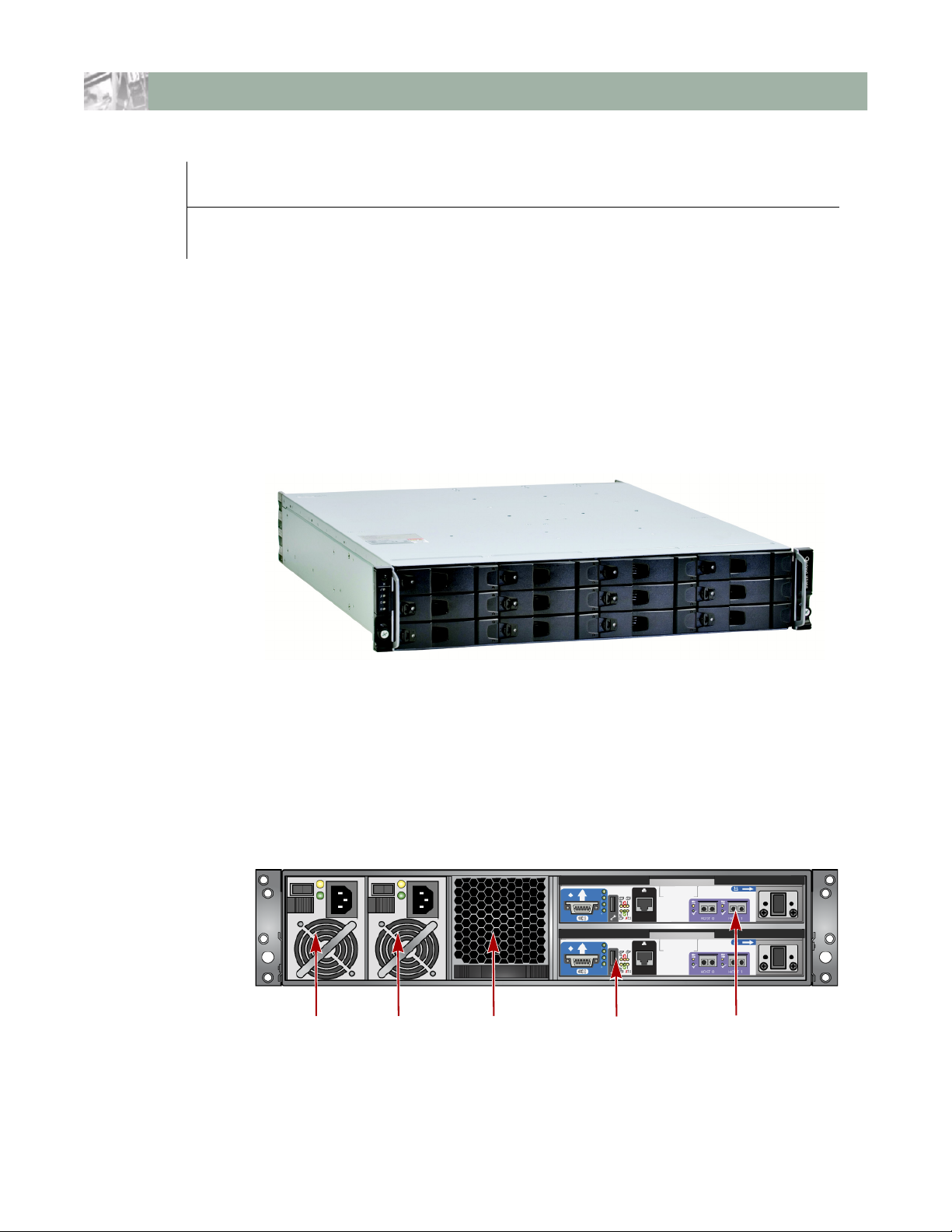
PSU 0 PSU 1 Cooling Module RAID Controller 0 RAID Controller 1
1
Introduction
The ULTAMUS™ RAID 1200 platform is a 2U (rack space) disk drive chassis
housing twelve low profile (1 inch high), 3.5 inch form factor disk drives, which can
be either SAS or SATA drive types. The design concept is based on a chassis
subsystem together with a set of plug-in modules.
Figure 1-1: ULTAMUS RAID 1200 Storage Array
Expansion is achieved by connecting ULTAMUS RAID 1200x expansion units to
the main array. Multiple arrays are connected together using SAS patch cables, up
to a total of five chassis, including the ULTAMUS RAID 1200 main array. See
“Connecting Multiple Arrays” on page 2-10.
ULTAMUS RAID 1200 Array
Figure 1-2: ULTAMUS RAID 1200 Rear Module Layout
10400165-101 01/2008 ©2007-2008 Overland Storage, Inc. W 1-1
Page 7
ULTAMUS RAID 1200 Hardware Setup Guide Introduction
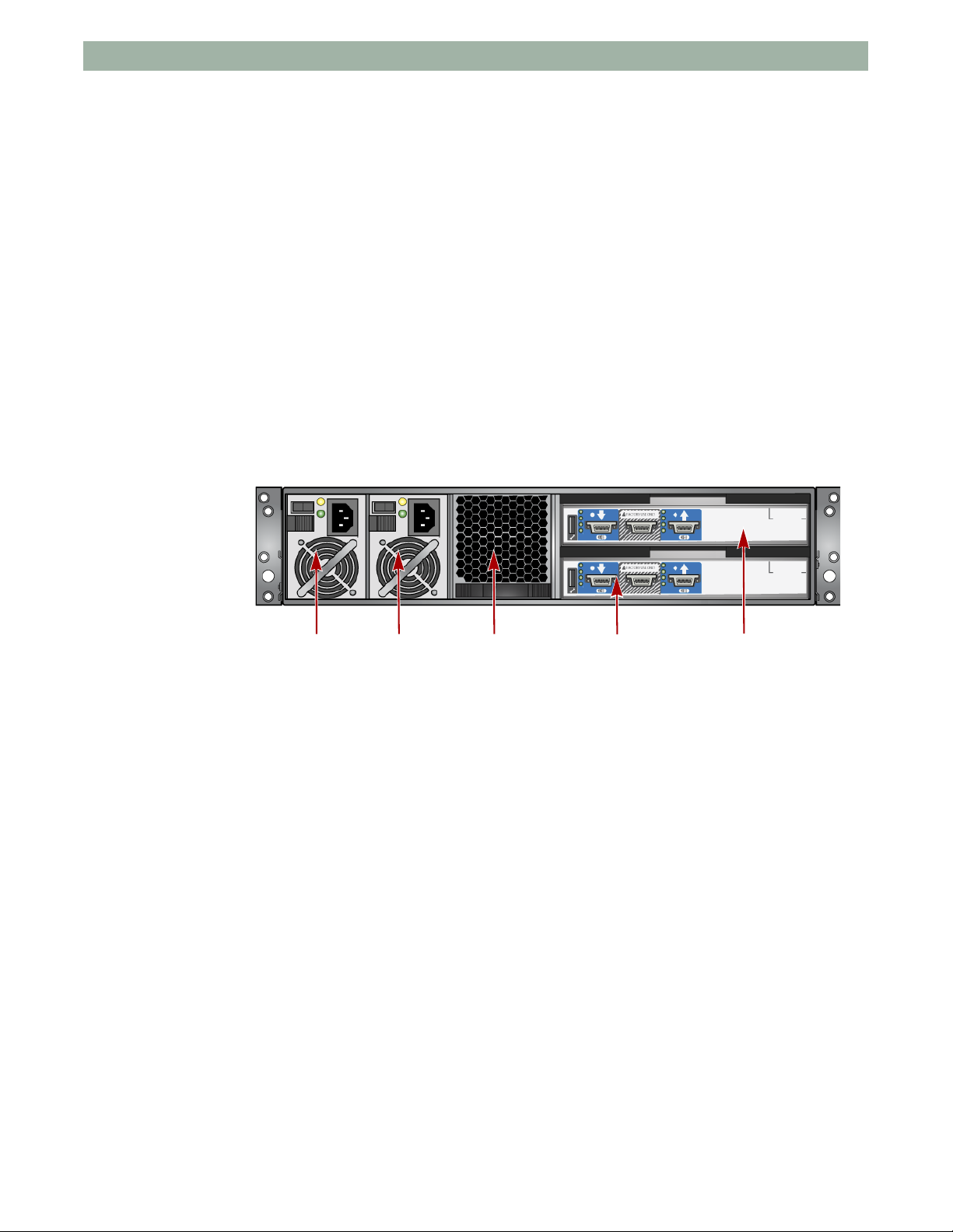
PSU 0 PSU 1 Cooling Module Expansion Module 0 Expansion Module 1
The ULTAMUS RAID 1200 as supplied (Figure 1-2 on page 1-1) contains:
• Chassis and backplane with integral (front panel mounted) Operator’s Panel
(see “Operator’s Panel” on page 1-3).
• Up to twelve (12) drive carrier modules, using either SAS or SATA disk
drives.
• Blank carrier modules in all unused drive bays to maintain airflow.
• Two plug-in Power Supply modules (PSU).
• One plug-in Cooling Fan module.
• Up to two (2) plug-in RAID Controller modules, incorporating the
ULTAMUS RAID manager software.
NOTE: If only one RAID module is installed, then a blank module must be fitted in
the unused slot. The RAID module must be in the lower Slot 0 and the blank
module in the upper Slot 1.
ULTAMUS RAID 1200x Expansion Array
Chassis
Figure 1-3: ULTAMUS RAID 1200x Rear Module Layout
The ULTAMUS RAID 1200x Expansion Array as supplied (Figure 1-3) contains:
• Chassis and backplane with integral (front panel mounted) Operator’s Panel
(see “Operator’s Panel” on page 1-3).
• Up to twelve (12) Drive Carrier Modules, using either SAS or SATA disk
drives.
• Blank carrier modules in all unused drive bays to maintain airflow.
• Two plug-in Power Supply modules (PSU).
• One plug-in Cooling Fan module.
• Two (2) plug-in Expansion (Disk I/O) modules.
The chassis consists of a sheet metal enclosure assembly containing a backplane
printed circuit board (PCB) and module runner system.
• The chassis front panel incorporates an integral Operator’s (OPS) Panel.
• The Backplane PCB provides logic level signal and low voltage power
distribution paths.
10400165-101 01/2008 ©2007-2008 Overland Storage, Inc. W 1-2
Page 8

ULTAMUS RAID 1200 Hardware Setup Guide Introduction
NOTE: The OPS Panel is
supplied as an integral
part of the array core
product and is not user
replaceable.
• The chassis is fitted with 19-inch rack-mounting features which enables it to
be fitted to standard 19-inch racks, and it uses 2 EIA units of rack space
(2U).
• The chassis assembly contains 12 drive bays at the front, each of which
accommodates the appropriate plug-in drive carrier module. The 12 drive
bays are arranged in 3 rows of 4 drives (Figure 1-4).
Figure 1-4: Drive Carrier Layout
• At the rear, the ULTAMUS RAID 1200 chassis assembly contains five plug-
in module bays to house two Power Supply modules, a Cooling Fan module
and two RAID Controller modules (fitted horizontally).
• The ULTAMUS RAID 1200x Expansion Array is similar to the ULTAMUS
RAID 1200, except Expansion Disk I/O modules are used instead of the
RAID Controller modules.
Operator’s Panel
The ULTAMUS RAID 1200 front panel incorporates an Operator’s (OPS) Panel
with four LEDs. The OPS Panel provides a high level indication of the operation of
the chassis. See
conditions.
Manual Self-Test
Pressing the Alarm Reset button when no error conditions are occurring starts an
LED self-test. Pressing the button again stops the self-test, or if an error condition
occurs while the self-test is ongoing, the test terminates. During the self-test you
initially hear two beeps followed by the OPS panel System Fault, Logical Fault,
and Box Identify LEDs, along with the Drive Carrier lower Fault LEDs (amber),
flashing continuously.
“OPS Panel LEDs” on page A-3 for details of the LED status
Figure 1-5: LED Layout on OPS Panel
10400165-101 01/2008 ©2007-2008 Overland Storage, Inc. W 1-3
Page 9

ULTAMUS RAID 1200 Hardware Setup Guide Introduction
Audible Alarms
The ULTAMUS RAID 1200 array includes an Audible Alarm which indicates
when a fault state is present. The following conditions will activate the Audible
Alarm:
• Fan Fault
• Voltage Out Of Range
• Over Temperature
• Thermal Overrun
• System Fault
• Logical Fault
• PSU Fault
• Removal Of One PSU
When the audible alarm sounds, it can be muted by pressing the Alarm Mute
push-button, which is incorporated in the chassis front panel. When muted, the
alarm continues to sound with short, intermittent beeps while the fault state
exists. The alarm will not silence until the issue that caused the alarm is
corrected.
10400165-101 01/2008 ©2007-2008 Overland Storage, Inc. W 1-4
Page 10

CHAPTER
2
Installing and Connecting
The following procedures describe the installation of an ULTAMUS RAID 1200
storage or expansion array and highlight some prerequisite requirements and
good handling practices which we encourage you to follow to ensure a successful
installation in the safest manner.
CAUTION: Ensure that you have fitted and checked a suitable anti-static wrist or
ankle strap and observe all conventional ESD precautions when handling modules
and components. Avoid contact with backplane components and module
connectors, etc. Use only the power cords/cables supplied or those which match
the specification in “AC Power Cords” on page B-2.
Preparation of Site and Host Server
Before you begin, make sure that the site where you intend to set up and use your
ULTAMUS RAID 1200 storage or expansion array has the following:
• Standard AC power from an independent source or a rack Power
Distribution Unit with a UPS.
• A host computer, running a supported OS, with a standard FC HBA (host
bus adapter) with the latest BIOS and drivers. Follow the instructions
provided with your HBA and install the HBA and its driver software.
NOTE: The ULTAMUS RAID 1200 supports widely-used operating systems; however,
deployment on Microsoft Windows requires the INF driver file which is found
on the ULTAMUS RAID 1200 Software and Documentation CD.
10400165-101 01/2008 ©2007-2008 Overland Storage, Inc. W 2-1
Page 11

ULTAMUS RAID 1200 Hardware Setup Guide Installing and Connecting
Unpacking the ULTAMUS RAID 1200 Array
The contents of the shipping box are:
• One ULTAMUS RAID 1200 storage array or ULTAMUS RAID 1200x
expansion array
• This quick start guide
• Accessory Kit that contains:
• Two AC power cables
• Rack-mounting rail kit with hardware
• ULTAMUS RAID 1200 Software and Documentation CD
• For a storage array only, the kit also contains these items:
• Serial cable for service use only
• Two SFP modules per RAID Controller module (up to four)
• Drive lock key (torx driver)
• For an expansion array only, the kit also contains two SAS cables
NOTE: Do not discard the serial cable or drive lock key. They may be required for later
servicing of the array.
Rack Installation Prerequisites
The ULTAMUS RAID 1200 chassis is designed for installation into an industry
standard 19-inch cabinet capable of holding the array.
• Minimum depth 700mm (27.6 inches) from front flange to rear metalwork
(excludes rear cabling).
• Weight: up to 32kg (70 lb.) dependent upon configuration per chassis.
• A minimum gap of 25mm (1 inch) clearance between the rack cover and
front of drawer; and 50mm (2 inches) rear clearance between rear of drawer
and rear of rack is recommended in order to maintain the correct air flow
around the chassis.
• The rack should present a maximum back pressure of 5 pascals (0.5mm
water gauge).
Rack Mounting Rail Kit
A set of mounting rails is available for use in 19-inch rack cabinets. These rails
have been designed and tested to handle the maximum chassis weight and to
ensure that multiple ULTAMUS RAID 1200 arrays can be installed without loss of
space within the rack. Use of other mounting hardware can cause some loss of rack
space.
Please contact your supplier to ensure suitable mount rails are available for the
rack you are using.
10400165-101 01/2008 ©2007-2008 Overland Storage, Inc. W 2-2
Page 12
ULTAMUS RAID 1200 Hardware Setup Guide Installing and Connecting
Installation Procedures
Installation consists of assembling the rails, mounting the rails in a rack, and
inserting the unit into the rack using the rails.
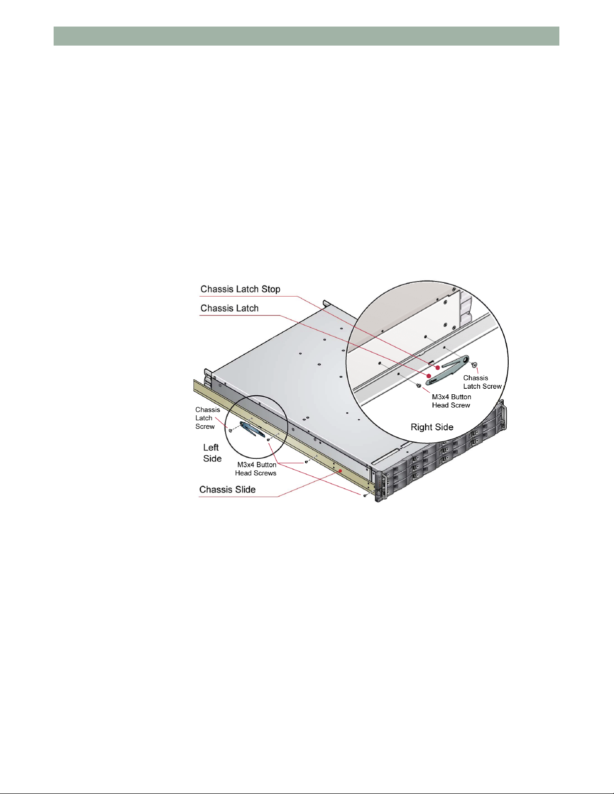
Installing Slide Rails on Chassis
Refer to the detail drawings supplied with the rack mounting rail kit for further
information.
To install slide rails
1. Attach left and right slides to the chassis sides using six (6) M3x4 button
head screws.
2. Assemble the left and right chassis latches using the chassis latch screws.
Ensure that the latch is oriented as shown in the below illustration, with the
spring arm located against its stop.
Figure 2-1: Position and Orientation of Chassis Latches
NOTE: On the right side, the latch spring arm points toward the top; on the left side
the latch spring arm points toward the bottom.
Installing Rack Brackets in 19-Inch Rack
NOTE: The brackets are universal and will fit either side.
To assemble the rack brackets to the rack posts
1. Locate the guide pin at the rear of each bracket and insert the pin into a rear
rack post hole. Attach the bracket to the rear rack post using the washers
and screws supplied. The screws should be left loose.
2. Extend the rail to fit between the rack posts.
3. Attach the bracket to the front rack post using the washers and screws
supplied. The screws should be left loose.
10400165-101 01/2008 ©2007-2008 Overland Storage, Inc. W 2-3
Page 13

ULTAMUS RAID 1200 Hardware Setup Guide Installing and Connecting
Remove nut when using the
tapped hole rack posts.
4. Tighten the two clamping screws located along the inside of the rear section
of the rack bracket.
Mounting the ULTAMUS RAID 1200 Array in the Rack
10400165-101 01/2008 ©2007-2008 Overland Storage, Inc. W 2-4
Figure 2-2: Rack Rail Assembly Procedure
WARNING: Due to the weight of each rack-mounted array when it is fully extended,
you should install arrays in the rack cabinet from the bottom up. Extending a array
that has empty spaces beneath it might cause the rack to tip forward and cause
personal injury. To avoid injury or damage to equipment, Overland strongly
recommends that two people lift the array into the rack.
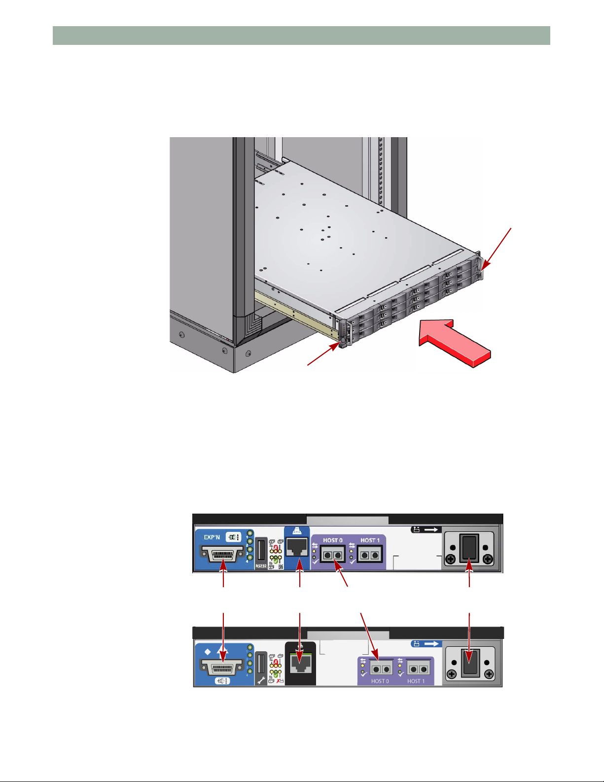
To install the array in the rack
1. Lift the array and align it with the rack rails.
2. Carefully insert the chassis slides into the rack rails and push the chassis
completely into the rack cabinet.
3. Tighten the rear rack bracket mounting screws (previously left loose).
Page 14
ULTAMUS RAID 1200 Hardware Setup Guide Installing and Connecting
Fastener
Fastener
Same
Connection
Same
Connection
Same
Connection
Same
Connection
4. Withdraw the chassis until it reaches the hard stops (approximately 400mm
(15.75 inches)). Tighten the front rack bracket mounting screws (previously
left loose).
5. Push the array completely into the rack cabinet and secure to the front of the
rack using the captive fasteners on the front flanges.
Figure 2-3: Captive Fastener Locations for Securing Array
Controller Card Connections
Some controller cards have different labeling schemes but all sockets are used for
the same connections.
Storage Array Connectors
10400165-101 01/2008 ©2007-2008 Overland Storage, Inc. W 2-5
Figure 2-4: Main Storage Array Labeling Schemes
Page 15

ULTAMUS RAID 1200 Hardware Setup Guide Installing and Connecting
Same
Connection
Same
Connection
Same
Connection
Expansion Array Connectors
Figure 2-5: Expansion Array Labeling Schemes
Management Interfaces
The following management interfaces are provided and used to configure, manage,
and monitor the ULTAMUS RAID 1200 storage array.
ULTAMUS RAID manager Software
ULTAMUS RAID manager software is a full-featured graphical HTML-based
software suite designed to configure, manage and monitor the ULTAMUS RAID
1200 storage array.
ULTAMUS RAID manager comprises the ULTAMUS RAID manager server that
runs as a background service on the RAID Controller Module and the ULTAMUS
RAID embedded HTML-based front end interface that is accessed using a web
browser on a host system.
The ULTAMUS RAID manager server discovers array storage devices, manages
and distributes message logs, and communicates with other ULTAMUS RAID
manager servers installed on the same local and external subnet networks. It
incorporates a web server, Apache 2.0, that provides the interface between the
ULTAMUS RAID manager server and GUI. During installation the web server is
automatically configured. See
Fibre Channel Interface
The RAID Controller module provides two Fibre Channel SFP interface
connections.
“ULTAMUS RAID manager Setup” on page 4-2.
The RAID Controller module provides bidirectional connection between the Fibre
Channel host side interface and the drives. The drives will not be presented to the
Host until they are configured and mapped by the controller.
10400165-101 01/2008 ©2007-2008 Overland Storage, Inc. W 2-6
NOTE: There are no external terminators required with Fibre Channel architecture and
any drive can be hot plugged during operation.
Page 16

ULTAMUS RAID 1200 Hardware Setup Guide Installing and Connecting
Two SFP modules per RAID Controller module are included in the accessory kit
(up to four).
To install the SFP modules
1. With the handle on the SFP module closed, push the SFP fully into the slot
until it seats (click).
2. Connect the Fibre Channel cable to the SFP.
3. Perform Steps 1–2 for each SFP module.
Each RAID Controller module can be connected to up to 2 independent Host Bus
adapters or switch ports. Some typical configurations utilizing two RAID
Controller modules and either one or two HBAs are shown in
Figure 2-6 through
Figure 2-10.
NOTE: Configurations utilizing multiple controllers sharing same expansion chassis are
not supported.
IMPORTANT: Optical modules must be UL (or other North American NRTL)
recognized component, and the laser in the module must comply with Laser Class 1,
US 21 CFR (J) and EN 60825-1.
Contact your supplier for a list of qualified optical SFP components.
Figure 2-6: Single Host, Single HBA, and Single Controller Connections
10400165-101 01/2008 ©2007-2008 Overland Storage, Inc. W 2-7
Page 17

ULTAMUS RAID 1200 Hardware Setup Guide Installing and Connecting
Figure 2-7: Dual Host, Single HBA, and Single Controller Connections
Figure 2-8: Single Host, Dual HBAs, and Dual Controller Connections
10400165-101 01/2008 ©2007-2008 Overland Storage, Inc. W 2-8
Page 18

ULTAMUS RAID 1200 Hardware Setup Guide Installing and Connecting
Figure 2-9: Dual Hosts, Dual HBAs, and Dual Controller Connections
Figure 2-10: Dual Host, Single HBAs, and Dual Controller Connections (Switch)
10400165-101 01/2008 ©2007-2008 Overland Storage, Inc. W 2-9
Page 19

ULTAMUS RAID 1200 Hardware Setup Guide Installing and Connecting
ULTAMUS RAID 1200
ULTAMUS RAID 1200X
Storage Array
Expansion Array 1
ULTAMUS RAID 1200X
Expansion Array 2
ULTAMUS RAID 1200X
Expansion Array 3
ULTAMUS RAID 1200X
Expansion Array 4
Ethernet Connection
An RJ45 10/100Base-T Ethernet port allows the controller to be connected to a
network to enable out-of -band management and monitoring using the embedded
ULTAMUS RAID manager software.
Ensure that the PC is connected either directly or via a switched LAN to the
Ethernet.
IMPORTANT: Only shielded CAT5e (or better) cables should be used for connection
to the Ethernet port for EMC conformance.
Connecting Multiple Arrays
Additional ULTAMUS RAID 1200x expansion chassis can be connected to the
main array. Multiple chassis are connected together using SAS patch cables, up to
a maximum of 5 chassis including the main RAID chassis. A maximum multiple
array configuration is shown in
Figure 2-11.
Figure 2-11: Connecting Additional Expansion Arrays
10400165-101 01/2008 ©2007-2008 Overland Storage, Inc. W 2-10
Page 20

ULTAMUS RAID 1200 Hardware Setup Guide Installing and Connecting
Column 1 Column 2 Column 3 Column 4
Row
1
2
3
Drive Slot Arrangement
Each array has twelve drives which are referenced by their location (Figure 2-12).
Drives are numbered by column/row.
Figure 2-12: Drive Carrier Layout
Drive Location Rules
The ULTAMUS RAID 1200 arrays support two different types of disk drives: SAS,
and SATA. In order to allow optimal configurations to be built, the following rules
should be observed:
• Different drive types (i.e., SAS and SATA) cannot be mixed in the same
column. You must populate using all the same drive types per column:
• Slots 1, 5, 9 = column 1
• Slots 2, 6, 10 = column 2
• Slots 3,7,11 = column 3
• Slots 4, 8, 12 = column 4
• To achieve optimum performance, chassis should be populated in the
following drive location sequence:
a. First, column 1;
b. followed by column 3;
c. then column 2;
d. and finally, column 4.
• If a change in drive technology is required, then a new column of drives
should be populated.
Engaging the Anti-Tamper Locks
The anti-tamper locks are fitted in the drive carrier handles and are accessed
through the small cutout in the latch section of the handle. Drives are installed
with the locks set in the locked position.
To de-activate the locks
1. Carefully insert the lock key provided into the cutout in the handle and into
its socket.
10400165-101 01/2008 ©2007-2008 Overland Storage, Inc. W 2-11
Page 21

ULTAMUS RAID 1200 Hardware Setup Guide Installing and Connecting
2. Rotate the key in a counter-clockwise direction until the red indicator is no
longer visible in the aperture beside the key (Figure 2-13).
Figure 2-13: Indicator Aperture Showing Drive Lock Status
3. Remove the key.
NOTE: Activation of the lock is the reverse of this procedure.
AC Power Cord Connection
After performing any grounding checks, attach and secure the power cords to the
unit (
Figure 2-14).
Grounding Checks
If a Rack Distribution System is being used, perform these checks to ensure that a
safe grounding system is provided.
1. Ensure power is removed from the rack.
2. Connect the ULTAMUS RAID 1200 power cord to the rack distribution
3. If a direct connection is made with the ULTAMUS RAID 1200 power cord,
4. Check for continuity between the earth pin of the IEC 320 connector on one
Figure 2-14: Power Supply Connections
and the array.
ensure that the power cord is connected to the array.
CAUTION: Some electrical circuits could be damaged if external signal cables
or power control cables are present during the grounding checks.
of the Power Supply modules and any exposed metal surface of the
ULTAMUS RAID 1200 chassis.
10400165-101 01/2008 ©2007-2008 Overland Storage, Inc. W 2-12
Page 22

ULTAMUS RAID 1200 Hardware Setup Guide Installing and Connecting
Attach AC power cords
1. Swing the Cable Strain Relief Bale out of the way and plug the power cord
into the PSU socket.
2. Place the bale over and onto the cord.
3. Repeat Steps 1–2 for the other PSU and cord.
CAUTION: The power connections must always be disconnected prior to removal of
the Power Supply module from the chassis.
10400165-101 01/2008 ©2007-2008 Overland Storage, Inc. W 2-13
Page 23

CHAPTER
3
Power On
Power Up the Array
CAUTION: Do not operate this equipment until the ambient temperature is within
the specified operating range. If the drives have been recently installed ensure they
have had time to acclimatize before operating them.
IMPORTANT: Before you power up an ULTAMUS RAID 1200 or 1200x array for the
first time, ensure that all the modules are firmly seated in their correct bays at the
rear of the unit.
IMPORTANT: When powering up a system with expansion arrays, power up the
expansion arrays first, then power up the main storage array.
1. Connect the AC cables from the array PSUs to a Power Distribution Unit
(PDU) on the rack (or AC source).
2. If necessary, turn on or plug in the PDUs.
3. If your array PSUs come with power switches, move them to the ON (|)
position.
When the array power is activated, all LEDs on the OPS Panel are
illuminated. During a normal startup, the System Fault LED will flash for a
second then go out, but the remaining LEDs continue to stay illuminated as
the array becomes ready. Then, when all systems are operating normally,
only the Power On LED remains illuminated.
4. Once the array is ON, power on the Host system.
NOTE: If power is lost for any reason, on restoration of power the array restarts
automatically.
Power Supply Module LEDs
Each Power Supply module incorporates two LEDs: Power On/OK and Module
Fault LEDs. Under normal conditions the Power On/OK LED should be
illuminated a steady green.
10400165-101 01/2008 ©2007-2008 Overland Storage, Inc. W 3-1
Page 24

ULTAMUS RAID 1200 Hardware Setup Guide Power Up the Array
Starting the Drives
The drives in the chassis should automatically start when power is applied to the
array. If this does not occur, one of the following conditions can exist:
• If there is only one Power Supply module present, the drive motors will spin
up in a delayed sequence.
• There can be a power problem (an alarm and Power Fault LED indication
would normally be active).
Disk Drive LEDs
Each drive carrier incorporates two LED indicators, an upper (green) and lower
(amber).
• In normal operation the green LED will be ON and will flicker as the drive
operates.
• In normal operation, the amber LED is OFF. The amber LED is also OFF if
there is no drive present.
• If the amber LED is flickering, drive identification is set from the software.
• If the amber and green LEDs are ON, there is a drive fault.
• If the green LED is OFF when the amber LED is ON, a power control circuit
failure is indicated.
Starting ULTAMUS RAID manager
Upon start-up, the ULTAMUS RAID manager looks at the user preferences
settings to determine if an IP address has been configured. It then initializes the
network interface in one of these ways:
• If an IP address is defined, ULTAMUS RAID manager initializes the
network interface using the defined IP address.
• If an IP address is not defined, ULTAMUS RAID manager attempts to get a
DHCP IP address.
• If an IP address (static or DHCP) cannot be determined, the software uses a
default IP address of 10.1.1.5 for Controller 0 and 10.1.1.6 for Controller 1.
• If an error is encountered, ULTAMUS RAID manager assigns it the IP
address 10.1.1.7. See “ULTAMUS RAID manager Setup” on page 4-2 for
more details.
The Subnet Mask is set to 255.0.0.0.
NOTE: To identify the new DHCP IP address lease, use the urmsetup.exe program
located on your Software and Documentation CD.
10400165-101 01/2008 ©2007-2008 Overland Storage, Inc. W 3-2
Page 25

ULTAMUS RAID 1200 Hardware Setup Guide Power Up the Array
Power Off Process
The array can be powered down at any time. If cached contents are present (see
Cache Active LED on the RAID Controller in section
page A-4), they are preserved by the internal battery.
• If the array is left in shutdown state for an extended period, the batteries
discharge and the cached data is lost.
• If the backup battery is allowed to discharge, upon power up the write-back
cache is disabled; however, when the battery is recharged, the write-back
cache is automatically re-enabled.
• To ensure that the cache is flushed to disks, stop all host I/O operations from
the applications. Allow sufficient time for the controller to write the cache
data to the drives. The Cache Active LED goes out indicating the cache is
now cleared or flushed. This will prevent the battery from discharging.
To Perform a Shutdown
IMPORTANT: When shutting down a system with expansion arrays, shut down the
main storage array first, then shut down the expansion arrays.
“RAID Module LEDs” on
1. From the ULTAMUS RAID manager main screen, click the Controller icon.
2. When the Controller Information screen appears, click the SHUTDOWN
button.
3. Repeat for the remaining controllers.
4. When the array has completed its shutdown, isolate the AC power from the
chassis by disconnecting the power cords.
10400165-101 01/2008 ©2007-2008 Overland Storage, Inc. W 3-3
Page 26

CHAPTER
ULTAMUS RAID manager Software
4
ULTAMUS RAID manager software is a full-featured HTML-based software suite
designed to configure, manage, and monitor ULTAMUS RAID arrays. It allows
you to manage and monitor the storage solutions from either a local host or from a
remote host located on the intranet or Internet.
Volume Size Reporting
The capacity of most disk drives is reported from the controller using decimal
system expressed in GB (1
use binary system to define the same space in GB (1
This can cause a visual discrepancy of approximately seven percent (7%) between
what the controller reports and what the operating system reports.
GB = 1,000,000,000 bytes). Many operating systems
GB = 1,073,741,824 bytes).
For example, an array of six drives can be reported as 733 GB by ULTAMUS RAID
manager, but Microsoft Windows reports it as 682.89
The volume size is the same amount whether it is reported in base-10 or base-2, or
MB vs. GB.
NOTE: The controller reserves small amount of capacity for configuration data.
Troubleshooting Assistance
To assist you when troubleshooting problems with your system, the Event Logs
appendix, located in the ULTAMUS RAID manager User Guide (on your
ULTAMUS RAID 1200 Software and Documentation CD) and the online help
provide a list of all the events that can occur, along with a possible cause and the
action to take.
GB.
10400165-101 01/2008 ©2007-2008 Overland Storage, Inc. W 4-1
Page 27

ULTAMUS RAID 1200 Hardware Setup Guide ULTAMUS RAID manager Software
ULTAMUS RAID manager Setup
When the ULTAMUS RAID manager Setup Program is run, it broadcasts UDP
packets and any embedded ULTAMUS RAID manager module will reply with
UDP packets containing their information. A list of uninitialized systems is
displayed. Uninitialized systems are those that have not had the default user
name and password changed. Even if a configuration is created with arrays and
logical drives but the login name and password have not been changed, it will still
be considered an uninitialized system. During the process of configuring an
embedded module, you will be required to enter a new password and confirm that
password. The default password is password.
Setting up the ULTAMUS RAID manager
1. Insert the ULTAMUS RAID 1200 Software and Documentation CD into
your CD drive. The autorun program automatically starts the navigation
menu.
2. Click ULTAMUS RAID manager Setup Program.
The Welcome screen is shown (Figure 4-1).
Figure 4-1: Setup Wizard Welcome Screen
3. At the Welcome screen, review the information and click Next.
The program begins searching for Embedded ULTAMUS RAID manager
modules (Figure 4-2 on page 4-3).
The Uninitialized screen lists any uninitialized systems it finds with their
MAC addresses.
NOTE: If all the systems found are initialized, the wizard displays the Initialized
screen.
10400165-101 01/2008 ©2007-2008 Overland Storage, Inc. W 4-2
Page 28

ULTAMUS RAID 1200 Hardware Setup Guide ULTAMUS RAID manager Software
Figure 4-2: Searching for Available Modules
At the third screen, those modules with their default password intact are
displayed with their MAC address in an Uninitialized Systems field.
4. From the Uninitialized screen, select the MAC address of the system you
wish to configure (
Figure 4-3):
a. To use a DHCP server to assign your IP address, check the
Use DHCP box (Check box 1).
b. To manually configure your network setting, uncheck the Use DHCP
box and enter the necessary information in the appropriate fields.
Figure 4-3: Select Module for Configuration
5. Enter a new password (field 6) and confirm the new password (field 7).
6. Click Configure.
10400165-101 01/2008 ©2007-2008 Overland Storage, Inc. W 4-3
Page 29

ULTAMUS RAID 1200 Hardware Setup Guide ULTAMUS RAID manager Software
7. Repeat Steps 4–6 to configure each uninitialized system in the displayed
list.
When all of the modules are initialized, the wizard displays a message
indicating that all systems are configured. It then re-scan for systems. If
none are found, the Initialized screen is displayed.
IMPORTANT: During this rescan, if an uninitialized module is added to the
network (same subnet mask), or a module’s password is returned to the
default, the wizard displays the Uninitialized screen again.
8. Select the MAC address of the embedded module you wish to start and click
Launch ULTAMUS RAID manager.
Figure 4-4: Initialized Screen
9. Your default web browser opens with a login screen. Enter the login name
and new password, then click OK.
The ULTAMUS RAID manager main screen opens.
Using the ULTAMUS RAID manager
The detailed instructions for setting up and using your ULTAMUS RAID manager
software features are provided in a separate document, the ULTAMUS RAID
manager User Guide, found on your ULTAMUS RAID 1200 Software and
Documentation CD.
10400165-101 01/2008 ©2007-2008 Overland Storage, Inc. W 4-4
Page 30

APPENDIX
A
Overview
ULTAMUS RAID 1200 and 1200x arrays include a processor and associated
monitoring and control logic to enable them to diagnose problems within the
array’s power, cooling, RAID Controller or Disk I/O modules, and drive systems.
The sensors for power and cooling conditions are housed within the Power Supply
modules. There is independent monitoring for each array.
If a fault is indicated on the OPS Panel, refer to “Disk I/O Module LEDs” on
page A-2.
Initial Start-up Problems
Faults and Troubleshooting
Faulty Cords
First check that you have wired up the subsystem correctly. Then, if the cords are
missing or damaged, or the cord plugs are incorrect contact your supplier for a
replacement.
Alarm Sounds On Power Up
See “Audible Alarm” on page A-6.
Green Controller OK LED on RAID Controller Not Lit
Check that the Rx and Tx cables have not been reversed during installation. Also
check that the SFP is properly seated and that the ends of optical cables are clean
and undamaged. If the condition persists, try replacing the SFP and/or cables.
Connect the cable to the RS-232 port and to your COM port or terminal, and in
your terminal window start a data capture:
• Try removing and re-inserting the RAID Controller.
• Try power cycling the array while monitoring the boot process from the terminal.
• If you are still unable to capture and examine the boot process to determine the
cause, contact your supplier for a replacement.
10400165-101 01/2008 ©2007-2008 Overland Storage, Inc. W 1-#
Page 31

ULTAMUS RAID 1200 Hardware Setup Guide Faults and Troubleshooting
Computer Doesn’t Recognize the ULTAMUS RAID 1200 Array
1. Check that the FC interface cables from the ULTAMUS RAID 1200 array to
the host computer are fitted correctly.
2. Check that all drive carrier modules have been correctly installed and that
the LEDs on all installed drive carrier modules are illuminated Green. Note
that the drive LEDs are not lit during drive spinup.
3. Check that there is a valid FC_AL signal present at the connector by
observing the state of the LEDs Host Port 0 Signal Good and Host Port 1
Signal Good (see
present check that the cable has not been inverted during installation. A
green LED indicates that the signal is present. If there is no signal present,
see
“Green Controller OK LED on RAID Controller Not Lit” on page A-1.
4. Check the RAID Controller module setup as follows:
a. Check that the RAID Controller module has been correctly installed, and
all external links and cables are secured.
b. Check that the maximum cable length has not been exceeded.
5. Check that the RAID Controller module is properly set up at the software
interface (ULTAMUS RAID manager or VT-100 RCU).
“Disk I/O Module LEDs” on page A-2). If there is no signal
Status Indicators (LEDs)
The ULTAMUS RAID 1200/1200x arrays use these LED conventions:
• Green LEDs are always used for good or positive indication.
• LEDs Flashing Green or Flashing Amber indicate that non-critical
conditions exist.
• Steady Amber LEDs indicate there is a critical fault present within the
module.
Disk I/O Module LEDs
LED Functions State Description
IN (Green) ON
OUT (Green) ON
Drive Carrier LEDs
Flashing
OFF
Flashing
OFF
Ready
Active
Not Ready
Ready
Active
Not Ready
See “Drive Carrier Module Faults” on page A-6.
10400165-101 01/2008 ©2007-2008 Overland Storage, Inc. W A-2
Page 32

ULTAMUS RAID 1200 Hardware Setup Guide Faults and Troubleshooting
NOTE: The OPS Panel is
supplied as an integral
part of the array core
product and is not user
replaceable.
OPS Panel LEDs
The OPS Panel displays the aggregated status of all the modules. The LEDs are
shown in Figure A-1 and defined in Table A-1.
NOTE: The panel is supplied as an integral part of the enclosure assembly and is not
user replaceable.
Figure A-1: OPS Panel LEDs
Pressing the Alarm Reset button when no error conditions are occurring starts an
LED self-test. Pressing the button again stops the self-test, or if an error condition
occurs while the self-test is on-going, the test terminates. During the self-test you
initially hear two beeps followed by the OPS panel System Fault, Logical Fault,
and Box Identify LEDs and the Drive Carrier lower Fault LEDs (amber) flash
continuously.
Table A-1: OPS Panel LED Displays and What They Mean
OPS Panel LED Status
Power
On
(Green)
ON ON ON ON Single beep, two
System
Fault
(Amber)
Logical
Fault
(Amber)
Box
Identify
(Blue)
Other LEDs
and Alarms Description of State
Power-On Self-Test
double beep
ON Power ON, all functions
good
ON ON PSU Fault LED or
Cooling Fan Module
Fault LED
Any PSU Fault, Cooling
Fan Module Fault, or
Over/Under
Temperature Condition
ON ON RAID Controller Fault
A RAID Controller Fault
LED on the specific
controller
ON ON Drive Fault LED Drive failure has
occurred causing loss of
availability or
redundancy
10400165-101 01/2008 ©2007-2008 Overland Storage, Inc. W A-3
Page 33

ULTAMUS RAID 1200 Hardware Setup Guide Faults and Troubleshooting
Table A-1: OPS Panel LED Displays and What They Mean (Continued)
OPS Panel LED Status
Power
On
(Green)
RAID Module LEDs
The RAID Controller module incorporates the following LED indicators:
LED/Icon Description
Battery Fault This LED/icon appears between the controller’s ethernet and
System
Fault
(Amber)
Logical
Fault
(Amber)
Box
Identify
(Blue)
Other LEDs
and Alarms Description of State
ON ON Array is performing
background function
such as a parity check,
initialization, or
expansion
ON Chassis identification
mode. When illuminated
it identifies the specific
chassis
NOTE: A blank indicates the LED has no bearing on the specific state and is not
applicable.
RS232 ports.
Illuminated - Backup battery unit is missing, has low voltage, has
experienced a time-out on charge indicating a faulty battery, or
has experienced a fault in the charging circuitry.
Cache Active This LED/icon appears between the controller’s ethernet and
RS232 ports.
Illuminated - RAID Controller cache has data saved in memory but
not written to the disk array.
Controller Activity on
Drive Bank 0
This LED/icon appears between the controller’s ethernet and
RS232 ports.
Illuminated - RAID Controller has activity on the bank 0 disk drives
(Drives 1, 5, 9, 2, 6, 10).
Controller Activity on
Drive Bank 1
This LED/icon appears between the controller’s ethernet and
RS232 ports.
Illuminated - RAID Controller has activity on the bank 1 disk
drives. (Drives 3, 7, 11, 4, 8, 12).
Controller OK/Fault This LED/icon appears between the controller’s ethernet and
RS232 ports.
Illuminated Green - RAID Controller operation is normal.
Illuminated Amber - RAID Controller fault has occurred.
10400165-101 01/2008 ©2007-2008 Overland Storage, Inc. W A-4
Page 34

ULTAMUS RAID 1200 Hardware Setup Guide Faults and Troubleshooting
SAS Activity These LEDs appear adjacent to the SAS connectors.
Illuminated - Activity on the specific port (4 lanes).
FC Activity These LEDs appear adjacent to the Fibre Channel connectors.
Illuminated Amber - Activity on the specific port.
Illuminated Green - Valid loop connection.
Cooling Module LED
The Cooling module incorporates a Module Fault LED (Amber), defined in table
below:
Status Description
OFF Fan OK
ON Fan Fail
Power Supply Module LEDs
The Power Supply LED states are detailed in the table below.
• Under normal conditions the Power On LED should be illuminated steady
green.
• If a problem is detected the Module, a Fault LED will be illuminated steady
amber.
Power On & OK
(Green)
OFF OFF No AC power (either PSU)
OFF ON No AC power (this PSU only)
OFF ON PSU Fault (over temperature, over voltage, over
ON OFF AC present, PSU ON and OK
ON ON Fan Fault
Module Fault
(Amber) Status
current, or PSU fan fail)
10400165-101 01/2008 ©2007-2008 Overland Storage, Inc. W A-5
Page 35

ULTAMUS RAID 1200 Hardware Setup Guide Faults and Troubleshooting
Audible Alarm
The chassis subsystem includes an Audible Alarm which indicates when a fault
state is present. The following conditions will activate the Audible Alarm:
• Fan Fault
• Voltage Out of Range
• Over Temperature
• Thermal Overrun
• System Fault
• Logical Fault
• PSU Fault
• Removal of 1 PSU
Audible Alarm Mute
When the Audible Alarm sounds, it can be muted by pressing the Alarm Mute
push-button, located on the chassis front panel. Automatic muting will take place
after two minutes if the mute switch is not manually operated.
When the alarm is muted it will continue to sound with short intermittent beeps to
indicate that a problem still exists, It will be silenced when all problems are
cleared. (See also
“Thermal Warnings” on page A-9).
LED Test Mode
The Alarm Mute push-button can also be used to activate the self- test feature for
the LEDs on the OPS Panel. The test is activated when you press the Mute pushbutton while no faults are present. While the test is running all LEDs flash.
Drive Carrier Module Faults
Disk drive status is monitored by a green LED and an amber LED mounted on the
front of each Drive Carrier module, providing the following indications:
Activity (Green) Fault (Amber) State
OFF OFF No drive fitted.
ON OFF Drive Power ON.
ON/blink OFF OFF Drive Activity. LED can be off for a
ON Blink Drive Impacted.Any background
length of time during power up.
service, such as initialization.
ON ON Drive Fault.
OFF ON Power Control Circuit Failure.
10400165-101 01/2008 ©2007-2008 Overland Storage, Inc. W A-6
Page 36

ULTAMUS RAID 1200 Hardware Setup Guide Faults and Troubleshooting
Auto Start Failure
Unless otherwise selected at installation time, all drives in the chassis should
automatically start their motors after power is applied. If this has not occurred
there is a power problem (an alarm and power fault indication would normally be
active).
Troubleshooting
The following sections describe problems, with possible solutions, which can occur
with your ULTAMUS RAID 1200 array.
System Faults
Symptom Cause Action
• The CONTROLLER FAULT
LED illuminates AMBER on
the RAID Controller
module.
•Audible Alarm sounds.
NOTE: See also “Thermal Warnings” on page A-9.
Power Supply Faults
Symptom Cause Action
• OPS Panel SYSTEM FAULT
LED AMBER.
• An AMBER LED on one or
more Power Supply
modules.
•Audible Alarm sounds.
The ESI processor has
detected an internal fault on
one of the following
modules:
•PSU
• Cooling
• RAID Controller
CAUTION: To prevent overheating, do not operate the array with one power supply
removed for more than 30 minutes.
•Any power fault.
• A fan failure.
• A thermal condition which
could cause PSU
overheating.
• Fault on one of the
following modules:
• PSU
• Cooling
• Removal of 1 PSU
Replace faulty module as
appropriate:
•PSU
• Cooling
• RAID Controller
•Check AC/DC power
connections to Power
Supply module are live.
• Disconnect the Power
Supply module from
AC/DC power and remove
the module from the array,
Re-install: if problem
persists, replace Power
Supply module.
• Reduce the ambient
temperature.
• Replace faulty module as
appropriate:
• PSU
• Cooling
10400165-101 01/2008 ©2007-2008 Overland Storage, Inc. W A-7
Page 37

ULTAMUS RAID 1200 Hardware Setup Guide Faults and Troubleshooting
Thermal Control
The ULTAMUS RAID 1200/1200x arrays use extensive thermal monitoring and
take a number of actions to ensure component temperatures are kept low and also
to minimize acoustic noise. Air flow is from front to rear of the chassis.
Symptom Cause Action
If the ambient air is cool
(below 25° C (77° F)) and
the fans are observed to
increase in speed then
some restriction on airflow
may be causing additional
internal temperature rise.
NOTE: This is not a fault
condition.
The first stage in the thermal
control process is for the
fans to automatically
increase in speed when a
thermal threshold is
reached. This can be caused
by higher ambient
temperatures in the local
environment and may be
perfectly normal.
NOTE: This threshold
changes according
to the number of
drives and power
supplies fitted.
• Check the installation for
any airflow restrictions at
either the front or rear of
the chassis. A minimum
gap of 25mm (1 inch) at
the front and 50mm
(2 inches) at the rear is
recommended.
• Check for restrictions due
to dust build-up and clean
as appropriate.
• Check for excessive recirculation of heated air
from rear to the front. Use
in a fully enclosed rack
installation is not
recommended.
• Check that all Blank
modules are in place.
• Reduce the ambient
temperature.
10400165-101 01/2008 ©2007-2008 Overland Storage, Inc. W A-8
Page 38

ULTAMUS RAID 1200 Hardware Setup Guide Faults and Troubleshooting
Thermal Alarm
Symptom Cause Action
• OPS Panel SYSTEM FAULT
LED AMBER.
• An AMBER LED on one or
more Power Supply
module.
• Audible Alarm Sounding.
• Air temperature exiting
PSU above 55° C
(131° F).
• If the internal temperature
measured in the airflow
through the chassis
exceeds a pre-set
threshold a thermal alarm
will sound.
• Cooling Fan Module
failure.
• Check local ambient
environment temperature
is below the upper 40° C
(104° F) specification.
• Check the installation for
any airflow restrictions at
either the front or rear of
the chassis. A minimum
gap of 25mm (1 inch) at
the front and 50mm
(2 inches) at the rear is
recommended.
• Check for restrictions due
to dust build-up and clean
as appropriate.
• Check for excessive recirculation of heated air
from rear to the front. Use
in a fully enclosed rack
installation is not
recommended.
• If possible shutdown the
array and investigate the
problem before
continuing.
•Replace Cooling Fan
Module.
Thermal Warnings
Symptom Cause Action
• ALL AMBER LEDs on the
OPS Panel and on ALL
drive bays illuminated
flash.
•Audible Alarm sounds
almost continuously and
cannot be muted.
At a higher threshold than
the Thermal Alarm (this
should already have been
activated).
OR -
All fans have failed.
OR -
Only 1 fan operating and the
internal temperature is
40° C (104° F) or above.
10400165-101 01/2008 ©2007-2008 Overland Storage, Inc. W A-9
• Switch OFF immediately.
•Check for airflow
restrictions.
• Check Power Supply
module faults.
• Check for excessive local
temperatures.
Page 39

APPENDIX
B
Dimensions
Specifications
Chassis Inches mm
Height 3.46 87.9
Width across mounting flange 19.0 483
Width across body of chassis 17.6 447
Depth from flange to rear of chassis body 21.65 550
Depth from flange to maximum extremity of chassis (rear hold
down)
Depth from flange to furthest extremity at front of array 1.44 36.5
22.72 577
NOTE: Overland recommends that you use a rack with a depth of no less than 700mm
(27.55 inches) with this product.
Weight
Maximum Configuration 32kg (70.4 lb.)
Empty Chassis 9kg (19.8 lb.)
AC Power (350W PSU)
Voltage Range 100--240V AC Rated
Frequency 50/60 Hz
Inrush Current <30A @ 230V AC
Power Factor >0.98
Harmonics Meets EN61000-3-2
10400165-101 01/2008 ©2007-2008 Overland Storage, Inc. W 1-#
Page 40

ULTAMUS RAID 1200 Hardware Setup Guide Specifications
AC Power Cords
United States
Must be NRTL listed (National Recognized Test Laboratory, e.g., UL).
Cord type SV or SVT, 18 AWG minimum,
3 conductor, 4.5 M max length
Plug NEMA 5-15P grounding-type
attachment plug rated 120V 10A;
or
IEC 320 C14, 250V, 10A.
Socket IEC 320, C-13, 250V, 10A.
Europe & Others
General requirements:
Cord type Harmonized, H05-VVF-3G1.0
Socket IEC 320, C-13, 250V, 10A.
PSU Safety and EMC Compliance
Safety Compliance UL 60950-1
EMC Compliance CFR47 Part 15B Class A
Environment
Ambient Temperature and Humidity
Temperature Range Relative Humidity Max. Wet Bulb
Operational 5° C to 40° C
(41° F to 104° F)
Non-Operational 1° C to 50° C
(34° F to 122° F)
Storage 1° C to 60° C
(34° F to 140° F)
Shipping -40° C to 60° C
(-40° F to 140° F)
IEC 60950-1
EN 60950-1
EN55022
EN55024
8% to 80%
non-condensing
8% to 80%
non-condensing
8% to 80%
non-condensing
5% to 100%
non-precipitating
23° C (74° F)
27° C (80° F)
29° C (84° F)
29° C (84° F)
10400165-101 01/2008 ©2007-2008 Overland Storage, Inc. W B-2
Page 41

ULTAMUS RAID 1200 Hardware Setup Guide Specifications
Other Environmental Specifications
Parameter Limits
Airflow Array must be operated with low pressure rear
exhaust installation
(Back pressure created by rack doors and
obstacles not to exceed 5 pascals [0.5mm water
gauge])
Altitude, Operational 0 to 3045m (0 to 10,000 ft.)
Altitude, Non-Operational -305 to 12,192m (-1000 to 40,000 ft.)
Shock, Operational Vertical axis 5g peak 1/2 sine, 10ms
Shock, Non-Operational 30g 10ms 1/2 sine
Vibration, Operational 0.21grms 5-500 Hz Random
Vibration, Non-Operational 1.04grms 2-200 Hz Random
Vibration, Relocation 0.3g 2-200 Hz sine
Acoustics Sound Power Operating:
Less than 58 dB LwA measured at 23°C (74° F).
Sound Pressure Operating:
Less than 6.8 Bels LwA measured at 23°C (73° F)
Orientation & Mounting 19-inch rack mount (2 EIA Units)
Rack Rails To fit 800mm (31.50 inches) depth racks
compliant with IEC 297
Rack Characteristics Back pressure not exceeding 5 pascals (0.5mm
water gauge)
Safety & Approvals (pending)CE and UL
EN 60950-1, iEC 60950-1, UL 60950-1
EMC EN55022 (CISPR - A), FCC A
Interfaces - RAID Controller Module
Drive support See drive carrier specification
Attachment • (1) domain of 12 drives per RAID Controller
module
• (2) Fibre Channel Host Ports (Arbitrated Loop,
Point-Point & Fabric attachment supported)
• (2) SFP optical
• (1) SAS Expansion Port
• (1) SFF8470 connector (4 lane)
10400165-101 01/2008 ©2007-2008 Overland Storage, Inc. W B-3
Page 42

ULTAMUS RAID 1200 Hardware Setup Guide Specifications
Interfaces - Disk I/O Module
Drive support See drive carrier specification
Attachment • (1) domain of 12 drives per Disk I/O module
• (1) SAS Host Port (IN)
• (2) SFF8470 connectors (4 lane)
• (1) SAS Expansion Port (OUT)
• (1) SFF8470 connector (4 lane)
RAID Module Specification
Dimensions (internal) 103mm x 267mm (4 inches x 10.5 inches)
Component board area: 103mm x 240mm
(4 inches x 9.5 inches)
Speed Host Ports: two 4 Gb/sec. Fibre Channel, also
supporting 2 Gb/sec. and 1 Gb/sec. mode
Drive Ports: 3 Gb/sec. SAS, creates connections to
a single domain of 12 drives
Mounting Rear, horizontal in Bay 4
Connectors • (2) SFP connectors for Host 0 and Host 1 Ports,
to accommodate optical interconnects (LC to LC
cable), maximum length 500m
•(1
) 4 Lane
ports
• (1) RJ45, 10/100BaseT Ethernet port
• (1) RS232 port
SAS Expansion SFF connector OUT
Power Consumption 40W
10400165-101 01/2008 ©2007-2008 Overland Storage, Inc. W B-4
Page 43

ULTAMUS RAID 1200 Hardware Setup Guide Specifications
LED Functions
RAID Controller Module LED Status Indicators
LED Description
Battery Fault This LED appears between the controller’s
ethernet and RS232 ports.
Illuminated - Backup battery unit is missing, has
low voltage, has experienced a time-out on charge
indicated a faulty battery or has experienced a
fault in the charging circuitry.
Cache Active This LED appears between the controller’s
ethernet and RS232 ports.
Illuminated - RAID Controller cache has data saved
in memory but not written to the disk array.
Controller Activity on Drive Bank 0 This LED appears between the controller’s
ethernet and RS232 ports.
Illuminated - RAID Controller has activity on the
bank 0 disk drives. (Drives 1, 5, 9, 2, 6, 10)
Controller Activity on Drive Bank 1 This LED appears between the controller’s
ethernet and RS232 ports.
Illuminated - RAID Controller has activity on the
bank 1 disk drives. (Drives 3, 7, 11, 4, 8, 12)
Controller OK This LED appears between the controller’s
ethernet and RS232 ports.
Illuminated Green - RAID Controller operation is
normal
Controller Fault This LED appears between the controller’s
ethernet and RS232 ports.
Illuminated Amber - RAID Controller fault has
occurred
Host 0 Port Signal Good This LED when ON indicates that the incoming FC
signal is good
Host 1 Port Signal Good This LED when ON indicates that the incoming FC
signal is good
Host 0 Port Traffic
*
This LED when ON indicates that the Controller is
processing data on this port
Host 1 Port Traffic
*
This LED when ON indicates that the Controller is
processing data on this port
SAS Activity LED 1-4
*
These LEDs appear adjacent to each SAS
connector.
Illuminated - Activity on the specific port (4 lanes)
*These LEDs blink ON & OFF when there is module activity.
10400165-101 01/2008 ©2007-2008 Overland Storage, Inc. W B-5
Page 44

ULTAMUS RAID 1200 Hardware Setup Guide Specifications
Disk I/O Module Specification
Dimensions (internal) 103mm x 267mm (4 inches x 10.5 inches)
component board area: 103mm x 240mm
(4 inches x 9.5 inches)
Connectors (1) Host Port (IN):
SFF8470 connector (4 lane)
(1) Expansion Port (OUT):
SFF8470 connector (4 lane)
Attachment (1) SAS 4 lane 3 Gb/sec. wide port Host connector
(1) SAS 4 lane 3 Gb/sec. wide port Expansion
connector
LED Functions
LED LED State Definition
*
IN 1
*
IN 2
*
IN 3
*
IN 4
*
OUT 1
*
OUT 2
*
OUT 3
*
OUT 4
*These LEDs blink ON & OFF when there is lane activity.
GREEN I/O activity on this SAS port lane
GREEN I/O activity on this SAS port lane
GREEN I/O activity on this SAS port lane
GREEN I/O activity on this SAS port lane
GREEN I/O activity on this SAS port lane
GREEN I/O activity on this SAS port lane
GREEN I/O activity on this SAS port lane
GREEN I/O activity on this SAS port lane
Drive Carrier Module Specification
IMPORTANT: Operating ULTAMUS RAID 1200/1200x chassis with non-approved
drives may invalidate the warranty. Please contact your supplier for details of
approved drives.
Module Dimensions Height 27.05mm (1.06 inches)
Width 106.55mm (4.19 inches)
Depth 209.55mm (8.25 inches)
Weight 0.88kg (1.0" 36 GB drive)
Operating Temperature 5°C to 40°C (41° F to 104° F)
When installed in an ULTAMUS RAID 1200
chassis with dual Power Supply modules.
Power Dissipation 18.5 watts maximum
10400165-101 01/2008 ©2007-2008 Overland Storage, Inc. W B-6
 Loading...