

Page 1
SnapServer® N2000
Enter
Enter
This document describes how to unpack a SnapServer N2000
from Overland Storage and install it into a four-post, 32-inch
deep, 19-inch (EIA-310) rack. The N2000 comes with four empty
drive slots and the remaining eight slots filled with drive blanks.
It must be populated with four to twelve drives to be operational.
WARNING: To reduce the risk of electric shock or damage to
equipment, always remove any power cords while working with
the unit.
AVERTISSEMENT: Pour réduire le risque de choc électrique ou
endommagement de l'équipement, retirez toujours les cordons
électriques en travaillant avec l'appareil.
CAUTION: While working with the unit, observe standard
Electrostatic Discharge (ESD) precautions to prevent damage to
micro-circuitry or static-sensitive devices.
Quick Start Guide
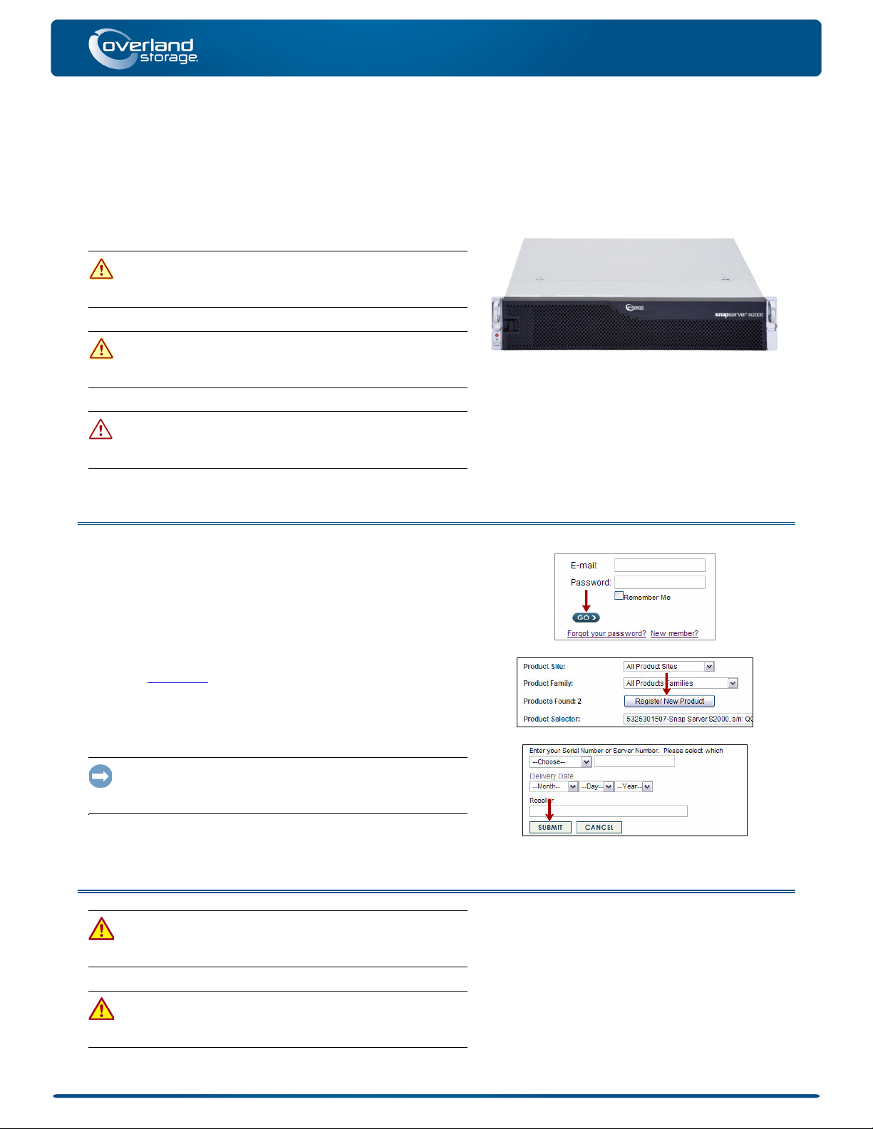
Step 1: Activate Your Warranty!
It is essential that you activate your warranty. Technical and
warranty support are not available until it is done:
1. Note the product serial number from the box label or on the
product.
2. Go to the Overland Storage web site:
http://www.overlandstorage.com/
Select Service & Support > My Products.
3.
4. At the Site Login
password, and click GO.
5. Click Register New Product.
6. Fill in the information and click Submit.
IMPORTANT: Within three business days, you’ll receive an e-mail
from Overland with your warranty certificate. Follow the
instructions included to complete the process.
, enter your e-mail address and
Step 2: Install Unit in Rack
WARNING: Use care during rack installation or removal to
prevent accidental tipping of the rack causing damage or
personal injury.
AVERTISSEMENT: soyez prudent lors de l'installation ou de
l'enlèvement du support afin d'empêcher le renversement
accidentel de la crémaillère, pour éviter dommages et blessures.
*10400287002*
10400287-002 03/2011 ©2010-11 Overland Storage, Inc. Page 1 of 7
Page 2
Quick Start Guide
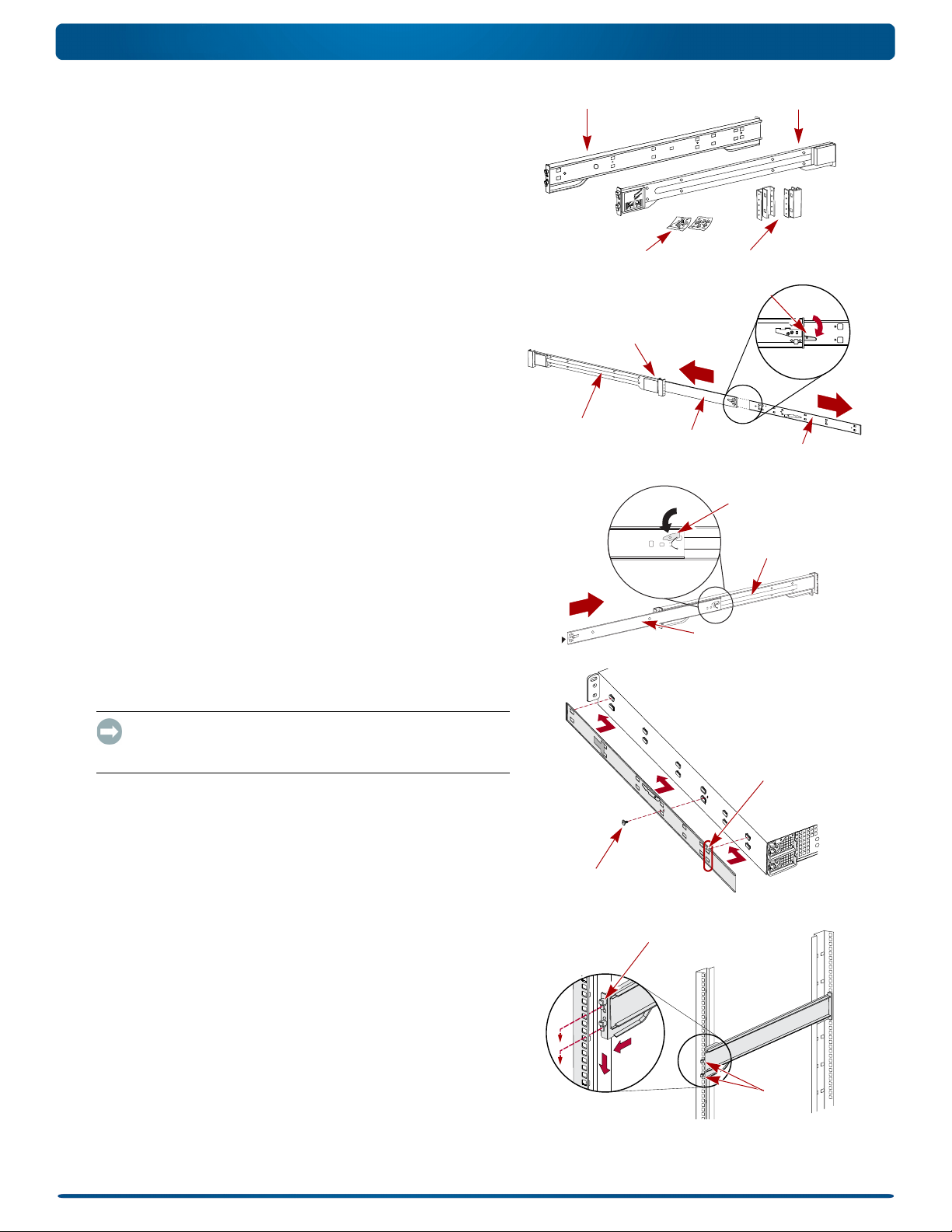
AdaptorsScrews
Left (LH) Rail Right (RH) Rail
Inner Member Latch
Middle Member Latch
(Hidden)
Middle Member
Outer Member
Inner Member
Latch
Middle Member
Outer Member
Screw
Align Rear
Holes to Tabs
Hooks
Tab
The included rail kit is adaptable for installation in squared-holed
and round-holed 19-inch (EIA-310) racks.
The rails are not universal. They are stamped LH (left) and RH
(right) and must be mounted on the appropriate side (when facing
the rack front).
NOTE: While the rail length can be shortened, any two-post telco-style
or other rack that is less than 29-inches in depth will NOT support this
server. Also, for threaded-hole racks, we recommend using a shelf.
Attach Inner Rails to Chassis
This procedure is required for all rack types:
1. Mark the screw holes on the rack where the rails will be
installed.
NOTE: Be sure rear holes are horizontally in line with the front
holes to ensure the unit remains level.
2. Remove the inner rail from the rail set:
a. Fully extend the rail set.
b. Push the inner member latch down, and remove the
inner rail.
c. Release and slide the middle member back into the
outer member.
3. Attach the right inner member:
a. Facing the chassis, position the rail against the right side
of the server with the locking tabs going through the holes
on the rail.
b. Slide the rail toward the front to lock it.
This may require some force as it is a tight fit.
c. Secure the rail with its Phillips screw.
4. Repeat Step 3 to install the left inner member.
IMPORTANT: Depending on your rack type, continue with either
the “Square-Holed Rack Installation” or “Round-Holed Rack
Installation.”
Square-Holed Rack Installation
1. Attach the left outer rail to the rack:
a. Position the rail against the inside of the rack front rail
with the hooks in line with the holes.
b. Insert the bracket front into the rack rail and press
down so that the hooks catch.
The spring-loaded tabs will extend into the hole to prevent
the rail from unhooking.
c. Slide the rear segment of the bracket rearward until the
d. Insert the bracket rear into the rack rail and press
hooks are in line with the correct holes.
down so that the hooks catch and the tabs lock.
10400287-002 03/2011 ©2010-11 Overland Storage, Inc. Page 2 of 7
Page 3
Quick Start Guide
A
B
(Front)
(Rear)
Adaptor
“A” Stamp
Bearing Shuttle
2. Repeat Step 1 for the right slide rail assembly.
3. Verify that the rails are level and straight.
Continue with “Install the Unit in the Rack.”
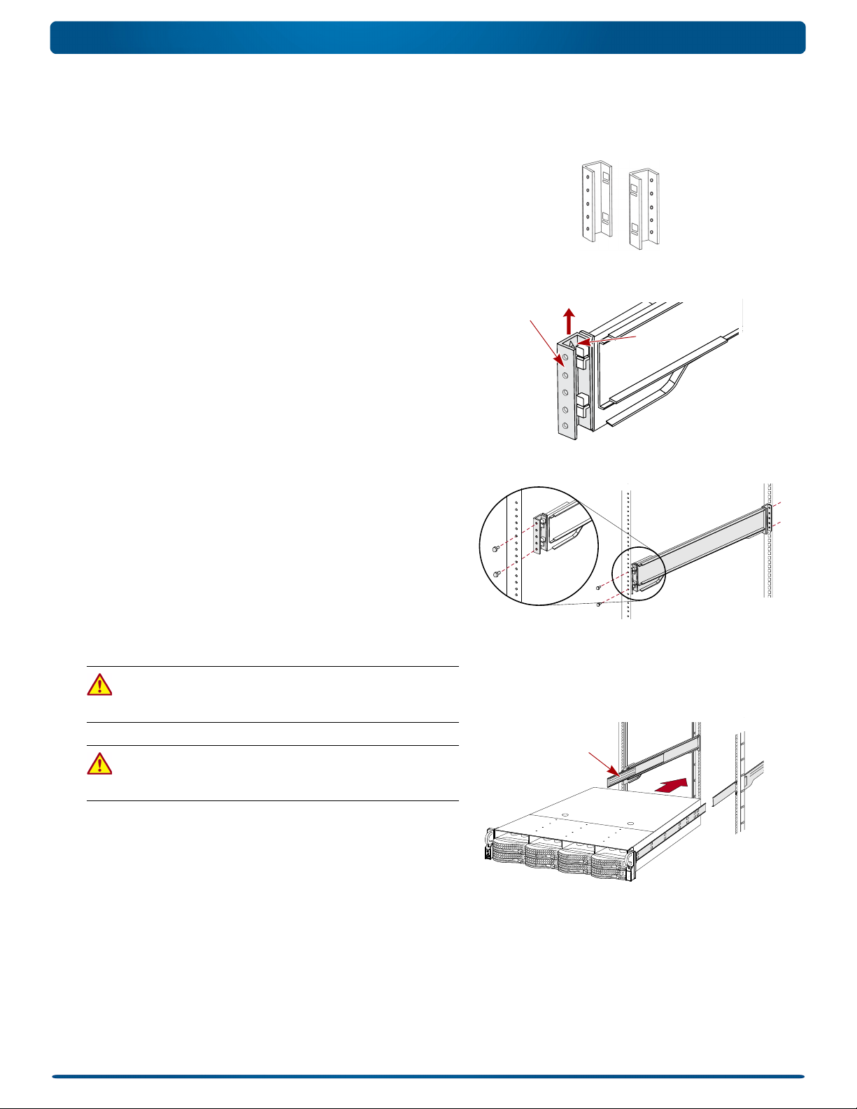
Round-Holed Rack Installation
Before installing the rails onto an unthreaded round-holed rack,
the round-hole rail kit adaptors must be installed on the ends of
the outer rails.
1. Attach the adaptors to both ends of the rail:
a. Position the adaptor stamped “A” at the front of the left
outer rail (end with the graphic label).
NOTE:
Make sure the stamp is at the top and the square adaptor
holes are aligned with the hooks on the outer rail.
b. Press the adaptor onto the hooks and slide it upwards
until it locks (clicks).
NOTE:
The rail buttons will snap into the square holes.
c. Repeat Steps a–b for the left rear adaptor (stamped “B”).
2. Facing the rack, position the left rail in the rack, aligning
the adaptor holes with the front left rack holes being used.
3. Using the screws from the kit, secure the front of the rail to
the rack.
4. Slide the rear rail segment rearward until the rear
adaptor holes are in line with holes being used.
5. Using the screws from the kit, secure the rear of the rail to
the rack.
6. Repeat Steps 1–5 for the right rail.
7. Verify that the rails are level and straight.
Continue the installation with “Install the Unit in the Rack.”
Install the Unit in the Rack
WARNING: It is recommended that a mechanical lifter (or at
least two people) be used during rack installation or removal to
prevent injury.
AVERTISSEMENT: pour éviter toute blessure il est recommande
qu'un monte-charge (ou deux personnes au moins) soit utilisé
lors de l'installation ou de l'enlèvement du support.
1. At the front, extend the middle rail members until they lock
(click).
2. Confirm that the ball-bearing shuttles are at the front.
3. Using a mechanical lifter or two people, insert the server into
the rack rails.
Lift the server to its install height and engage the inner
members on the server with the middle members
protruding from the rack, and slide the server into the rack
until it stops.
10400287-002 03/2011 ©2010-11 Overland Storage, Inc. Page 3 of 7
Page 4

Quick Start Guide
Supported Configurations
Rotational Speed A Rotational Speed B Blank Disk Drive
Unsupported Configurations
Do not include drives
with different RPMs in
the same column.
Rotational Speed A Rotational Speed B Blank Disk Drive
4. Slide the unit in and out a few times to ensure that the
N2000 does not bind.
If binding occurs, verify that the front and rear flanges are
mounted in the correct holes, readjusting the slide
positioning as necessary.
5. Using the two screws provided, secure the N2000 flanges to
the rack.
Step 3: Install the Drives
As shipped, the first four slots are empty and the remaining slots
have disk drive blanks. Any combination of 4 to 12 SAS and/or
SATA drives can be installed with blank drive carriers filling in
the empty slots. The drive assemblies are sold separately in either
single- or four-packs.
Recommended Drive Configurations
Before adding drive assemblies to a SnapServer N2000, the
following must be observed:
• Different capacity drives can be installed; however, they
should not be included in the same RAID array, because
capacity usage for all drives in the RAID is limited to the
capacity of the smallest drive member.
• Drives of different rotational speed (such as, SAS and SATA
drives) can be installed, but they should not be installed in
the same column or be separated from each other by a
column of different rotational speed drives. If you are
combining drives with different speeds, use the figures below
to plan where to place the disk drives.
Install Drives
NOTE: Do not remove the disk drives from their carriers. Doing so
voids the drive warranty.
As shipped, the first four slots are empty and the remaining slots
have disk drive blanks. Once the unit is in the rack, install all
your drives from the drive packs before continuing:
1. If a drive blank is in the slot where you are about to install
a disk drive, remove the blank by pressing the lever release
button and pulling it out.
2. Remove a drive assembly from the packaging.
3. Press the button to release the lever.
4. Position the drive assembly in front of the appropriate bay
and slide it in until resistance is felt.
5. Push the lever in to lock the assembly in the bay.
6. Repeat Steps 1–5 for each remaining drive carrier.
IMPORTANT: To maintain proper airflow and cooling, a drive
assembly or a blank drive carrier must be installed in every slot.
Leave drive blanks in any slots not used. No empty slots are allowed. A
minimum of four drives must be installed for proper operation.
10400287-002 03/2011 ©2010-11 Overland Storage, Inc. Page 4 of 7
Page 5

Quick Start Guide
Latch Pins
1 - AC Power
2 - Mouse Port*
3 - Keyboard Port*
4 - Dual USB Ports
5 - Serial Port*
6 - Video Port*
7 - Ethernet1 Port
8 - Ethernet2 Port
9 - SAS Port
1245678 93
* Unsupported for the SnapServer N2000.
Attach the Bezel
1. Insert the right bezel pins into the chassis right flange.
2. Push the latch in (toward the bezel center) and press the
bezel into place against the drives.
3. Release the latch so that the left pins fit in the left flange.
Step 4: Attach Cables and Power Cords
All cabling and power connections are located on the rear panel of
the SnapServer N2000. All unit cooling exhaust is handled
through the rear panel.
CAUTION: The speed/duplex setting on N2000 servers defaults
to autonegotiate. The networking switch or hub to which the
server is connected must also be configured to autonegotiate;
otherwise, network throughput or connectivity to the server may be
seriously impacted.
1. Plug the network connection into Ethernet1 port.
Using a Category 5e (or better) cable, connect Ethernet1
port on the server to a Gigabit Ethernet switch on the same
LAN as the management system.
NOTE: To take advantage of network bonding (load balancing or
failover), both data ports must be physically connected to the
network. For load balancing, connect them to the same switch on
the same subnet with the switch set to auto-negotiate. For failover,
connect them to different switches on the same subnet.
2. Connect any SanDisk E2000 expansion arrays using the
instructions that came with the units.
3. Attach the power cords to the AC Power sockets.
4. Plug the power cords into a UPS appliance or a properly
grounded AC power source.
NOTE: SnapServer systems are designed to work with APC-brand
USB or network-based UPS devices to automatically shut down
cleanly in the event of a power failure. You must configure the APC
unit both in the SnapServer’s Web Management Interface and in
the APC user interface.
Step 5: Initial Power Up
IMPORTANT: To properly initialize the server for use, power it ON
without powering ON any attached expansion units.
1. Turn the N2000 server ON by pressing and holding the
Power button for no more than one (1) second.
The System LED blinks green once per second. The first-time
self configuration takes a few minutes.
10400287-002 03/2011 ©2010-11 Overland Storage, Inc. Page 5 of 7
Page 6

Quick Start Guide
Power
Button
Power
Button
System
LED
http://support.overlandstorage.com/
support/snapserver-nas.htm
2. If any expansion arrays are attached:
IMPORTANT: To enable the N2000 to discover any expansion
arrays, turn ON all the arrays before powering ON your N2000.
a. Turn the N2000 server OFF by pressing and holding the
Power button for no more than one (1) second.
Wait for the server to shut down completely (all front
panel LEDs are OFF).
b. Turn ON any expansion arrays by pressing and holding
the Power button for no more than one (1) second.
Wait until all the array LEDs have stopped blinking.
c. When all the expansion arrays are up and running, turn
the N2000 server back ON.
Step 6: Connect for the First Time
NOTE: SnapServers are configured to acquire an IP address from a DHCP server. If no DHCP server is found on the network, the
SnapServer defaults to an IP address in the range of 169.254.xxx.xxx. You may not be able to see the server on your network until
you assign an IP address using SnapServer Manager (SSM).
• If you are installing your SnapServer N2000 on a network with a DHCP server, continue with “Connecting Using
the Server Name.”
• If your network does not have a DHCP server or name resolution services, continue with “Connecting Using the
SnapServer Manager.”
Connecting Using the Server Name
This procedure requires that name resolution services (via DNS or an equivalent service) be operational.
1. Find the server name.
The default server name is “SNAPnnnnnn,” where nnnnnn is the server number. For example, the name of a
SnapServer N2000 with a server number of 610019 is SNAP610019. The server number is a unique, numeric-only
string that appears on a label affixed to the top of the server in the left front corner.
2. In a Web browser, enter the server URL.
For example, enter “http://SNAPnnnnnn” (where SNAPnnnnnn is the server name).
3. Press Enter to open the Web View screen.
4. Log into the Web Management Interface.
In the login dialog box, enter admin as the user name and admin as the password, then click OK.
5. Complete the Initial Setup Wizard.
Your N2000 is ready to be configured for your specific environment and needs.
Connecting Using the SnapServer Manager
SSM is an administrative application that is Java-based,
platform-independent, and runs on all major platforms. SSM
provides administrators a single interface from which they can
discover any SnapServer on the network. You can download and
install SSM from:
http://support.overlandstorage.com/support/snapserver-nas.htm.
Be sure to install SSM on a computer residing on the same
network segment as your N2000.
NOTE: If you plan to run SSM on a Macintosh client, you must
upgrade the client to MacOS 10.2 or higher (required for JRE 1.4.0
or higher support).
10400287-002 03/2011 ©2010-11 Overland Storage, Inc. Page 6 of 7
Page 7

Quick Start Guide
SnapServer Manager Procedure
1. Launch SSM.
SSM discovers all SnapServers on its local network segment and displays their server names, IP addresses, and
other status information in the main console. If you do not have a DHCP server, there might be a delay before the
server appears on the network.
NOTE: To distinguish multiple SnapServers, you may need to find their default server names as explained in the previous
procedure.
2. If using a DHCP server, proceed to Step 3; otherwise, assign an IP address to the new server.
a. In SSM, right-click the server name.
b. Select Set IP Address.
c. Enter an IP address and a subnet mask, then click OK.
3. In SSM, right-click the server name and select Launch Web Administration.
4. Log into the Web Management Interface.
In the login dialog box, enter admin as the user name and admin as the password, then click OK.
5. Complete the Initial Setup Wizard.
Your N2000 is ready to be configured for your specific environment and needs.
Step 7: Additional Information
User Guides
For detailed information on configuring your SnapServer N2000,
refer to the SnapServer Administrator’s Guide for GuardianOS
6.5, the SnapServer Setup Guide for GuardianOS 6.5, or the
GuardianOS 6.5 Release Notes.
They are available online at:
http://support.overlandstorage.com/support/
snapserver-nas.htm
Click one of the links on the right side of the page to view the
appropriate GuardianOS document.
Warranty and Technical Support
For warranty and technical support information, see our Contact
Us web page:
http://www.overlandstorage.com/company/contact-us/
index.aspx
To search for more service information, visit our Expert
Knowledge Base System:
http://support.overlandstorage.com/kb
10400287-002 03/2011 ©2010-11 Overland Storage, Inc. Page 7 of 7
http://support.overlandstorage.com
You can get additional technical support on the Internet at the Overland Storage Support web page, or by contacting Overland Storage using
the information found on the Contact Us page on our web site.
 Loading...