

Page 1
Overland
Storage
SnapSAN™ S2000
User Guide
July 2011
10400277-004
Page 2

SnapSAN S2000 User Guide
©2010-11 Overland Storage, Inc. All rights reserved.
Overland®, Overland Data®, Overland Storage®, LibraryPro®, LoaderXpress®, Multi-SitePAC®, NEO®, NEO Series®, PowerLoader®,
Protection OS®, REO®, REO 4000®, REO Series®, Snap Care®, SnapDisk®, SnapServer®, StorAssure®, and XchangeNOW® are registered
trademarks of Overland Storage, Inc.
GuardianOS™, SnapWrite™, Snap Enterprise Data Replicator™, SnapSAN™, and SnapServer Manager™ are trademarks of Overland Storage,
Inc.
All other brand names or trademarks are the property of their respective owners.
The names of companies and individuals used in examples are fictitious and intended to illustrate the use of the software. Any resemblance to
actual companies or individuals, whether past or present, is coincidental.
PROPRIETARY NOTICE
All information contained in or disclosed by this document is considered proprietary by Overland Storage. By accepting this material the recipient
agrees that this material and the information contained therein are held in confidence and in trust and will not be used, reproduced in whole or
in part, nor its contents revealed to others, except to meet the purpose for which it was delivered. It is understood that no right is conveyed to
reproduce or have reproduced any item herein disclosed without express permission from Overland Storage.
Overland Storage provides this manual as is, without warranty of any kind, either expressed or implied, including, but not limited to, the implied
warranties of merchantability and fitness for a particular purpose. Overland Storage may make improvements or changes in the product(s) or
programs described in this manual at any time. These changes will be incorporated in new editions of this publication.
Overland Storage assumes no responsibility for the accuracy, completeness, sufficiency, or usefulness of this manual, nor for any problem that
might arise from the use of the information in this manual.
Version 4.4
Overland Storage, Inc.
9112 Spectrum Center Blvd.
San Diego, CA 92123
U.S.A.
Tel: 1.877.654.3429 (toll-free U.S.)
Tel: +1.858.571.5555 Option 5 (International)
Fax: +1.858.571.0982 (general)
Fax: +1.858.571.3664 (sales)
www.overlandstorage.com
10400277-004 07/2011 ©2010-11 Overland Storage, Inc. W ii
Page 3

This user guide explains how to install, setup, and use your new Overland Storage
SnapSAN S2000 appliance and its SnapSAN Manager Suite software to perform tasks
such as create arrays and logical volumes, modify configuration settings, and take
snapshots.
This guide assumes that you are familiar with computer hardware, data storage, and
network administration terminology and tasks. It also assumes you have basic
knowledge of Internet SCSI (iSCSI), Serial-attached SCSI (SAS), Serial ATA (SATA),
Storage Area Network (SAN), and Redundant Array of Independent Disks (RAID)
technology.
Product Documentation and Firmware Updates
Preface
Overland Storage SnapSAN product documentation and additional literature are
available online, along with the latest release of the SnapSAN S2000 software.
Point your browser to:
http://docs.overlandstorage.com/snapsan
Follow the appropriate link to download the latest software file or document. For
additional assistance, search at http://support.overlandstorage.com
Overland Technical Support
For help configuring and using your SnapSAN S2000, search for help at:
http://support.overlandstorage.com/kb
You can email our technical support staff at techsupport@overlandstorage.com or get
additional technical support information on the Contact Us
http://www.overlandstorage.com/company/contact-us/
For a complete list of support times depending on the type of coverage, visit our web
site at:
http://support.overlandstorage.com/support/overland_care.html
.
web page:
10400277-004 07/2011 ©2010-11 Overland Storage, Inc. W iii
Page 4
SnapSAN S2000 User Guide
Conventions
This user guide exercises several typographical conventions:
Convention Description & Usage
Boldface Words in a boldface font (Example) indicate items to select such
as menu items or command buttons.
Ctrl-Alt-r This type of format details the keys you press simultaneously. In
this example, hold down the Ctrl and Alt keys and press the r key.
NOTE A Note indicates neutral or positive information that emphasizes
or supplements important points of the main text. A note supplies
information that may apply only in special cases—for example,
memory limitations or details that apply to specific program
versions.
IMPORTANT An Important note is a type of note that provides information
essential to the completion of a task or that can impact the
product and its function.
CAUTION A Caution contains information that the user needs to know to
avoid damaging or permanently deleting data or causing physical
damage to the hardware or system.
WARNING A Warning contains information concerning personal safety.
Failure to follow directions in the warning could result in bodily
harm or death.
Menu Flow
Indicator
(>)
Information contained in this guide has been reviewed for accuracy, but not for
product warranty because of the various environments, operating systems, or
settings involved. Information and specifications may change without notice.
Words in bold font with a greater than sign between them
indicate the flow of actions to accomplish a task. For example,
Setup > Passwords > User indicates that you should press the
Setup button, then the Passwords button, and finally the User
button to accomplish a task.
10400277-004 07/2011 ©2010-11 Overland Storage, Inc. W iv
Page 5

Preface
Chapter 1 - Overview
SnapSAN S2000 Overview .......................................................................................................................... 1-1
SnapSAN S2000 Appliance .................................................................................................................. 1-1
SnapSAN Manager Suite Software ..................................................................................................... 1-1
Windows SnapSAN Manager ......................................................................................................... 1-2
Web Management Interface ........................................................................................................ 1-2
Chapter 2 - Installation and Setup
First Things First – Activate Your Warranty! ................................................................................................ 2-1
Recommended Drive Configurations ...................................................................................................... 2-2
SnapSAN S2000 Rack Installation Overview ............................................................................................ 2-2
Powering Up the SnapSAN S2000 ............................................................................................................. 2-3
Chapter 3 - Initial Configuration
Using the Windows SnapSAN Manager ................................................................................................... 3-1
Installing an iSCSI Initiator ..................................................................................................................... 3-1
Installing SnapSAN Manager Suite Software ..................................................................................... 3-1
Configuring the Appliance with Windows SnapSAN Manager ....................................................... 3-5
Using the Web Management Interface ................................................................................................. 3-10
Assigning a Static Network Address .................................................................................................. 3-11
Finding the DHCP Network Address ................................................................................................. 3-12
Appliance Monitor Display .......................................................................................................... 3-12
DHCP Server Client Table ............................................................................................................. 3-12
Configuring the Appliance ................................................................................................................ 3-13
Contents
Chapter 4 - Storage Management
Windows SnapSAN Manager Overview .................................................................................................. 4-1
Creating a SnapSAN Disk ........................................................................................................................... 4-2
Backing Up Data ........................................................................................................................................ 4-4
Using Snapshots ..................................................................................................................................... 4-4
Using Replicas ........................................................................................................................................ 4-5
Creating and Replicating a New Disk Simultaneously ............................................................... 4-6
Using Mirroring ....................................................................................................................................... 4-7
Synchronous Mirroring .................................................................................................................... 4-8
Asynchronous Mirroring .................................................................................................................. 4-8
Creating and Mirroring a New Disk Simultaneously .................................................................... 4-8
10400277-004 07/2011 ©2010-11 Overland Storage, Inc. W v
Page 6

SnapSAN S2000 User Guide Contents
Chapter 5 - PC and Servers Management
Introduction ................................................................................................................................................. 5-1
Overview Screen ........................................................................................................................................ 5-2
Create SnapSAN Disk ........................................................................................................................... 5-4
Disk Create Advanced Settings .................................................................................................... 5-5
Destroy SnapSAN Disk ........................................................................................................................... 5-9
Extend SnapSAN Disk .......................................................................................................................... 5-10
Manage Disk Task ............................................................................................................................... 5-10
Disk Tasks .............................................................................................................................................. 5-11
Rename Disk Task .......................................................................................................................... 5-11
Configure Auto Extension Task .................................................................................................... 5-12
Replicate Disk Task ........................................................................................................................ 5-12
Mirror Disk Task ............................................................................................................................... 5-13
Categories ........................................................................................................................................... 5-15
Properties ....................................................................................................................................... 5-15
Replication Category ................................................................................................................... 5-16
Mirroring Category ........................................................................................................................ 5-17
Paths Category ............................................................................................................................. 5-18
SnapSAN Replicas Category ................................................................................................................... 5-19
SnapSAN Replica Properties Management .................................................................................... 5-20
Using the Calendar to Recover Data ......................................................................................... 5-20
Properties & Scheduler Category ........................................................................................................... 5-22
Queued and Completed Tasks Category ............................................................................................. 5-23
Chapter 6 - Network Management
Overview ..................................................................................................................................................... 6-1
Setting Up Storage Groups ........................................................................................................................ 6-2
Discovery ..................................................................................................................................................... 6-3
Add Discovery Entry ............................................................................................................................. 6-4
Remove Discovery Entry ...................................................................................................................... 6-4
User Interface Preferences ........................................................................................................................ 6-5
About ...........................................................................................................................................................6-6
Chapter 7 - Appliance Management
Overview ..................................................................................................................................................... 7-1
Hard Disks Category ................................................................................................................................... 7-3
SnapSAN Pools Category .......................................................................................................................... 7-4
Manage a SnapSAN S2000 Pool ......................................................................................................... 7-6
Extend a SnapSAN Pool ....................................................................................................................... 7-7
Destroy a SnapSAN Pool ...................................................................................................................... 7-7
Create a SnapSAN Pool ....................................................................................................................... 7-8
SnapSAN Targets Category ..................................................................................................................... 7-10
Managing A SnapSAN Target ........................................................................................................... 7-11
Properties Category ...................................................................................................................... 7-11
Security Category ......................................................................................................................... 7-12
Portals ............................................................................................................................................. 7-14
Statistics .......................................................................................................................................... 7-15
Replication ..................................................................................................................................... 7-17
Mirroring a Target .......................................................................................................................... 7-18
Destroying A SnapSAN Target ........................................................................................................... 7-19
Creating A SnapSAN Target .............................................................................................................. 7-20
10400277-004 07/2011 ©2010-11 Overland Storage, Inc. W vi
Page 7

SnapSAN S2000 User Guide Contents
Extending A SnapSAN Target ............................................................................................................ 7-22
SnapSAN Replicas Category ................................................................................................................... 7-23
Manage SnapSAN Replica ................................................................................................................ 7-24
Create SnapSAN Replica ................................................................................................................... 7-26
Destroy SnapSAN Replica .................................................................................................................. 7-27
Network Category .................................................................................................................................... 7-28
Network Connections Category ....................................................................................................... 7-28
Properties Category ...................................................................................................................... 7-29
Advanced Category .................................................................................................................... 7-30
Statistics Category ........................................................................................................................ 7-31
DNS Category ..................................................................................................................................... 7-32
Routing Category ............................................................................................................................... 7-33
Properties Category ................................................................................................................................. 7-34
Hardware Monitoring Category ............................................................................................................. 7-36
Events Category ....................................................................................................................................... 7-37
Identification & Services Category ......................................................................................................... 7-38
Initiators Category .................................................................................................................................... 7-40
Notification Category .............................................................................................................................. 7-41
Statistics Category .................................................................................................................................... 7-43
Chapter 8 - Web Management Interface
Accessing the Web Management Interface .......................................................................................... 8-1
Overview and Usage ................................................................................................................................. 8-2
Home Tab .................................................................................................................................................... 8-3
Appliance Home Page ........................................................................................................................ 8-3
Content Area Links ............................................................................................................................... 8-3
Actions Available .................................................................................................................................. 8-3
System Tab ................................................................................................................................................... 8-3
System Information ............................................................................................................................... 8-4
Content Area Links ............................................................................................................................... 8-4
Actions Available .................................................................................................................................. 8-4
System Tab Subpages .......................................................................................................................... 8-5
System Configuration ..................................................................................................................... 8-5
System Firmware Upgrade ............................................................................................................. 8-6
Hardware Sensors Information ....................................................................................................... 8-6
System Power Settings .................................................................................................................... 8-7
Set Admin Password ....................................................................................................................... 8-7
System Diagnostics .......................................................................................................................... 8-8
Set System Date & Time .................................................................................................................. 8-9
System License .............................................................................................................................. 8-10
Secure Authentication Certificate ..............................................................................................8-11
Network Tab .............................................................................................................................................. 8-11
Network Information ........................................................................................................................... 8-12
Content Sections and Links ............................................................................................................... 8-12
Actions Available ................................................................................................................................ 8-13
Network Tab Subpages ...................................................................................................................... 8-13
Discovery ........................................................................................................................................ 8-14
Network Device Information ........................................................................................................ 8-16
Edit Network Device ..................................................................................................................... 8-17
Network Interface Information .................................................................................................... 8-17
Create Network Interface ............................................................................................................ 8-18
10400277-004 07/2011 ©2010-11 Overland Storage, Inc. W vii
Page 8

SnapSAN S2000 User Guide Contents
Edit Network Interface .................................................................................................................. 8-19
Delete Network Interface ............................................................................................................ 8-20
Network Route Information .......................................................................................................... 8-20
Create Network Route ................................................................................................................. 8-21
Specific Network Item Change Pages ....................................................................................... 8-21
Network Ping .................................................................................................................................. 8-22
Network Traceroute ...................................................................................................................... 8-23
Targets Tab ................................................................................................................................................ 8-24
Targets .................................................................................................................................................. 8-24
Content Sections and Links ............................................................................................................... 8-24
Actions Available ................................................................................................................................ 8-25
Target Tab Subpages ......................................................................................................................... 8-25
Target Information ........................................................................................................................ 8-25
Target Edit ...................................................................................................................................... 8-27
Extend Target ................................................................................................................................. 8-28
Target Delete ................................................................................................................................. 8-29
Target Disable/Enable .................................................................................................................. 8-29
Add ACL Entry to Target ............................................................................................................... 8-30
Target ACL Entry ............................................................................................................................ 8-30
Edit Target ACL Entry .................................................................................................................... 8-31
Remove Target ACL Entry ............................................................................................................ 8-31
Create Target ................................................................................................................................ 8-32
Add Initiator to Target .................................................................................................................. 8-33
Target Initiator View ...................................................................................................................... 8-34
Remove Initiator ............................................................................................................................ 8-34
Create Snapshot Target ............................................................................................................... 8-35
Add Replicant Host to Target ...................................................................................................... 8-36
Target Replicant Host Information ..............................................................................................8-38
Edit Replicant Host Details ............................................................................................................ 8-39
Remove Replicant Host from Target ........................................................................................... 8-40
Add Mirror Plex to Target .............................................................................................................. 8-40
Plex Information ............................................................................................................................. 8-41
Remove Mirror Plex ....................................................................................................................... 8-42
Change (Promote to) Management Plex ................................................................................. 8-43
Break Mirror Plex ............................................................................................................................ 8-43
Create Target Recovery Point ..................................................................................................... 8-44
Create Target on <Pool_name> ................................................................................................. 8-45
Export to USB Devices ......................................................................................................................... 8-45
Pools Tab .................................................................................................................................................... 8-46
Storage Pools ....................................................................................................................................... 8-46
Content Sections and Links ............................................................................................................... 8-46
Actions Available ................................................................................................................................ 8-47
Other Network Tab Subpages ........................................................................................................... 8-48
Subsystem Information ................................................................................................................. 8-48
Pool Information ............................................................................................................................ 8-49
Create Storage Pool ..................................................................................................................... 8-50
Add Global Hot Spare .................................................................................................................. 8-51
Remove Global Hot Spare ........................................................................................................... 8-52
Storage Journal Configuration .................................................................................................... 8-52
Set Neutral Storage Host .............................................................................................................. 8-54
Subsystem Rescan ..............................................................................................................
.......... 8-55
10400277-004 07/2011 ©2010-11 Overland Storage, Inc. W viii
Page 9

SnapSAN S2000 User Guide Contents
Delete Storage Pool ...................................................................................................................... 8-55
Extend Pool .................................................................................................................................... 8-56
Set Pool Cache ............................................................................................................................. 8-56
Pool Markers .................................................................................................................................. 8-57
Devices Tab ...............................................................................................................................................8-57
Devices ................................................................................................................................................ 8-58
Content Sections and Links ............................................................................................................... 8-58
Actions Available ................................................................................................................................ 8-58
Other Device Tab Subpages ............................................................................................................. 8-59
Device Information ....................................................................................................................... 8-59
Events Tab ..................................................................................................................................................8-59
Events ................................................................................................................................................... 8-60
Actions Available ................................................................................................................................ 8-61
Other Device Tab Subpages ............................................................................................................. 8-61
Clear Events ................................................................................................................................... 8-61
Event Notification .......................................................................................................................... 8-61
Event Notification Setup ............................................................................................................... 8-62
Add Event Notification ................................................................................................................. 8-63
Remove Event Notification .......................................................................................................... 8-64
Test Event Notification .................................................................................................................. 8-64
Clear System Status ....................................................................................................................... 8-65
Replicant Tab ............................................................................................................................................ 8-65
Replicant Information ......................................................................................................................... 8-65
Content Sections and Links ............................................................................................................... 8-66
Actions Available ................................................................................................................................ 8-66
Other Device Tab Subpages ............................................................................................................. 8-66
Replicant Settings .......................................................................................................................... 8-67
Add ACL Entry to Replicant ......................................................................................................... 8-67
Create Replicant Volume ............................................................................................................ 8-68
Replicant Volume Information .................................................................................................... 8-69
Recovery Point Information ......................................................................................................... 8-70
Edit Replicant Volume .................................................................................................................. 8-71
Delete Replica Volume ................................................................................................................ 8-72
Recovery Point Target Mapping ................................................................................................. 8-72
Edit Replicant ACL Entry ............................................................................................................... 8-73
Remove Replicant ACL Entry ....................................................................................................... 8-73
Replicant ACL Entry ...................................................................................................................... 8-74
Chapter A - SnapServer Manager
Installing the SSM Software ....................................................................................................................... A-1
Launching SSM ......................................................................................................................................A-1
SnapSAN S2000 Discovery ....................................................................................................................A-2
Accessing Management Software .....................................................................................................A-2
Right-Click vs. Control-Click .................................................................................................................A-2
Chapter B - Expanding Capacity
Attaching Expansion Arrays ....................................................................................................................... B-1
Chapter C - Licenses & Copyright
GNU General Public License .................................................................................................................... C-1
GPL Version 2 ........................................................................................................................................ C-1
10400277-004 07/2011 ©2010-11 Overland Storage, Inc. W ix
Page 10

SnapSAN S2000 User Guide Contents
Lesser GPL ............................................................................................................................................. C-6
Copyright Notices and Licenses ............................................................................................................ C-13
Appendix D - VMware Plug-In
Install SnapSAN Manager Suite ................................................................................................................ D-1
Install VMware Plug-in ............................................................................................................................... D-1
Create Datastore ...................................................................................................................................... D-2
Appendix E - VSS Hardware Provider
Overview ..................................................................................................................................................... E-1
Theory of Operation ................................................................................................................................... E-1
Installation .................................................................................................................................................... E-2
System Requirements ........................................................................................................................... E-2
Hardware Requirements ................................................................................................................ E-2
Operating System Requirements ..................................................................................................E-2
Software Requirements .................................................................................................................. E-2
Installation .............................................................................................................................................. E-2
Verifying the Installation ....................................................................................................................... E-2
Uninstallation ......................................................................................................................................... E-3
System Setup ............................................................................................................................................... E-3
Using the Overland Hardware Provider for VSS ...................................................................................... E-3
Creating a Snapshot ............................................................................................................................ E-4
Listing Snapshots ................................................................................................................................... E-4
Exposing a Snapshot ............................................................................................................................. E-4
Example Using VSS ...................................................................................................................................... E-4
Storage Array Logical Drives versus Windows Volumes ......................................................................... E-5
Use of VSS Tools ...........................................................................................................................................E-6
Breaking a Snapshot Set ............................................................................................................................ E-6
Event Codes ................................................................................................................................................ E-6
Successful Messages ............................................................................................................................ E-7
Informational Messages ....................................................................................................................... E-7
Error Messages ....................................................................................................................................... E-7
Appendix F - Mirror Example
Overview ..................................................................................................................................................... F-1
Procedure .................................................................................................................................................... F-1
Overland Glossary & Acronym List
Index
10400277-004 07/2011 ©2010-11 Overland Storage, Inc. W x
Page 11
CHAPTER
1
Overview
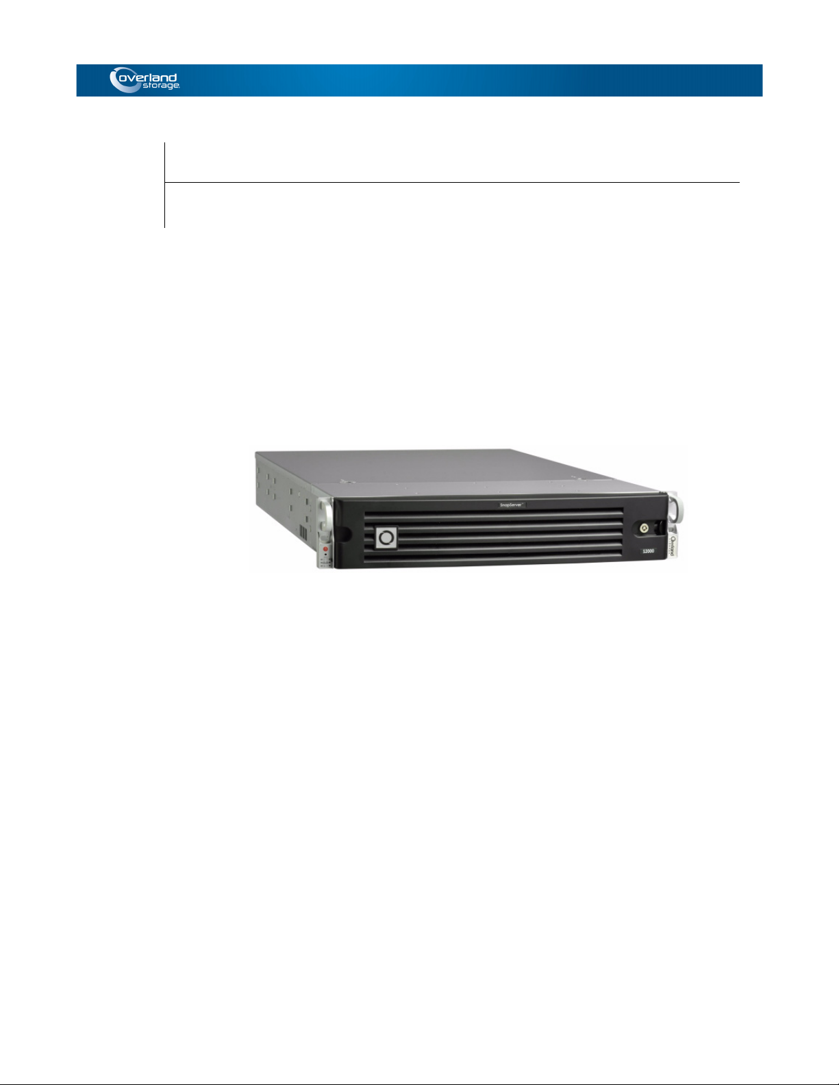
This manual describes how to use the Overland Storage SnapSAN S2000 system. The
appliance together with the SnapSAN S2000 software provides a flexible, intelligent,
iSCSI-based storage area network (SAN) solution for virtualized server environments
and the growing demand for data storage. With a SnapSAN S2000 appliance, you can
store, share, protect, and manage data through a single easy-to-use Windows or web
interface.
SnapSAN S2000 Overview
The SnapSAN S2000 has two main components: the appliance and its custom
software.
SnapSAN S2000 Appliance
This is a appliance connected to your local storage area network running the
SnapSAN S2000 software. The appliance manages a RAID controller which, in turn,
manages the physical operation of a group of hard disks. The S2000 makes this
networked disk storage look just like one or more local disks.
SnapSAN Manager Suite Software
This is storage management software that enables you to manage your data storage
effectively and efficiently with no special knowledge about the underlying technology
required. There are two versions available:
• Windows SnapSAN Manager – A Windows program run from a network
computer.
• Web Management Interface – A web-based interface on the SnapSAN that is
accessed by a browser.
10400277-004 07/2011 ©2010-11 Overland Storage, Inc. W 1-1
Page 12
SnapSAN S2000 User Guide
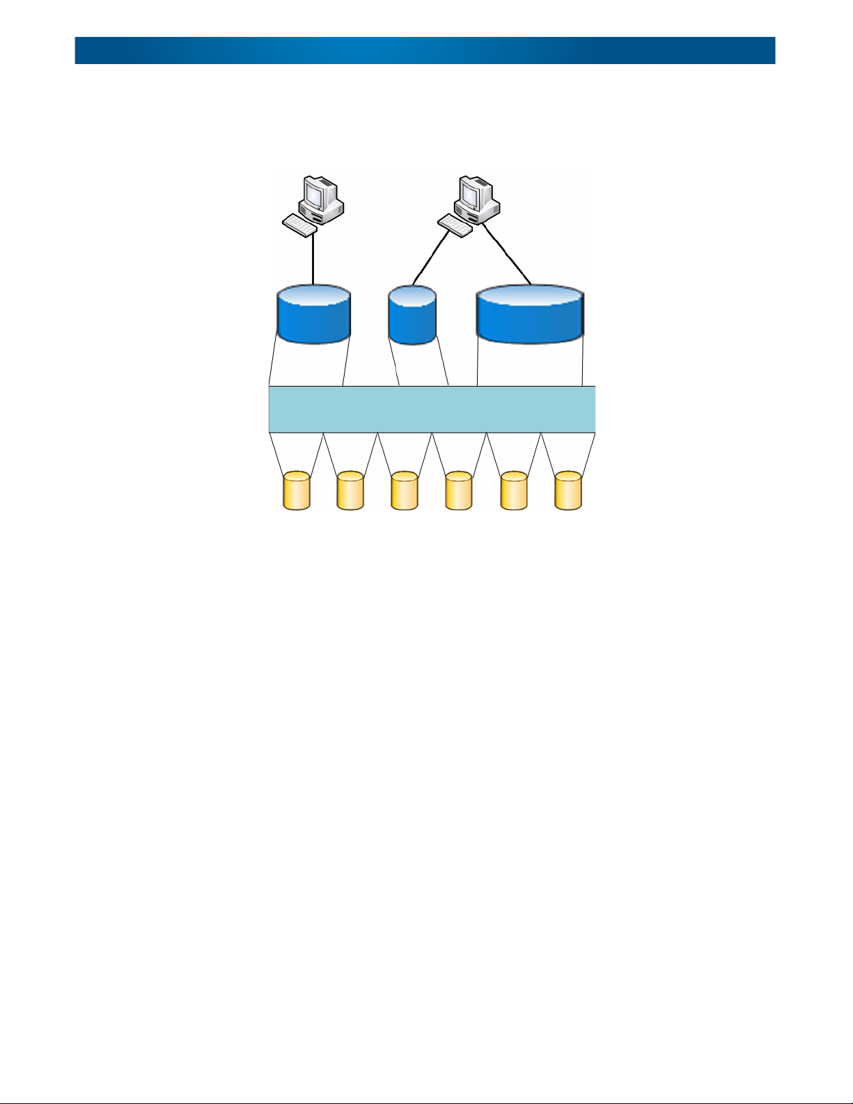
Host Computers
Disk Drives
RAID Pool
iSCSI Virtual
SAN Disks
The figure below illustrates how the SnapSAN S2000 software can map a set of
independent disk drives, connected to the network by a RAID controller, to a storage
pool from which seemingly “local” disks of user-defined size can be created and shared
by all the users on the network.
Windows SnapSAN Manager
The Windows SnapSAN Manager is a Windows program that provides you with an
easy way to manage your data storage. You can use it to perform the following storage
management tasks:
• Configure your appliance
• Create new disks from storage on the SnapSAN S2000 appliance.
• Protect the data by controlling shared access to it.
• Provide a high level of data security, using the built-in reliability that comes
with RAID technology.
• Monitor the way that data is used and then adapt the data storage to fit this
usage pattern, giving users optimal access to their data.
• Back up data quickly and efficiently using SnapSAN S2000 support for
snapshots, disk replication (optional), and mirroring (optional).
Web Management Interface
The Web Management Interface is a browser-based tool for managing your data
storage. You can use the Web Management Interface to perform the following storage
management tasks:
• Configure your appliance
• Create new disks from storage on a specific SnapSAN S2000 appliance.
• Check the logs for a specific SnapSAN S2000 appliance.
• Verify error or fault messages regarding a specific SnapSAN S2000 appliance.
10400277-004 07/2011 ©2010-11 Overland Storage, Inc. W 1-2
Page 13
CHAPTER
2
Installation and Setup
This chapter explains how to install a SnapSAN S2000 appliance. Sections in this
chapter include:
• First Things First
• SnapSAN
• Powering Up the SnapSAN S2000
S2000 Rack Installation Overview
– Activate Your Warranty!
First Things First – Activate Your Warranty!
Before installing your new unit, it is essential that you activate your Overland
warranty. Technical and warranty support are not available until this is done:
1. Go to the Overland Storage web site at:
http://www.overlandstorage.com/
2. Select Service & Support > My Products.
3. At the Site Login
NOTE: If you are not yet a member, click “New member?” and follow the instructions
given. It’s free and easy!
, enter your email address and password.
4. Under the My Products tab, click Register New.
5. Fill in the information and click Submit.
IMPORTANT: You will receive an email from Overland with your warranty certificate.
Review it carefully and verify that the product and address information is accurate. If
any errors are found, email us at: warranty@overlandstorage.com. Otherwise, follow the
instructions in the email to complete the registration process.
10400277-004 07/2011 ©2010-11 Overland Storage, Inc. W 2-1
Page 14
SnapSAN S2000 User Guide
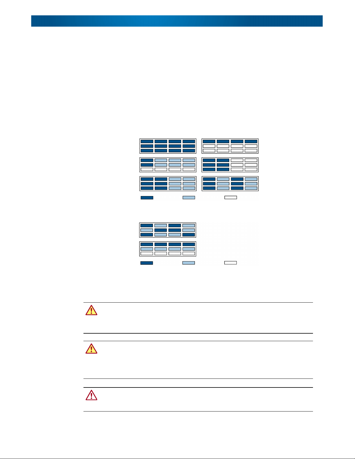
Supported Configurations
Rotational Speed A Rotational Speed B Blank Disk Drive
Unsupported Configurations
Do not include drives
with different RPMs in
the same column.
Rotational Speed A Rotational Speed B Blank Disk Drive
Recommended Drive Configurations
Before installing or adding drives to a SnapSAN S2000 appliance, the following must
be observed:
• Different capacity drives can be installed; however, they should not be included
in the same RAID array, because capacity usage for all drives in the RAID is
limited to the capacity of the smallest drive member.
• Drives of different rotational speed (such as, SAS and SATA drives) can be
installed, but they should not be installed in the same column. If you are
combining drives with different speeds, use the figures below to plan where to
place the disk drives.
SnapSAN S2000 Rack Installation Overview
10400277-004 07/2011 ©2010-11 Overland Storage, Inc. W 2-2
WARNING: It is recommended that a mechanical lifter (or at least two people) be used
to raise and align the unit to prevent injury during installation. Use care when inserting
or removing a unit into or out of a rack to prevent the accidental tipping of the rack causing
damage or personal injury.
AVERTISSEMENT: il est recommandé que la mécanique lifter (ou au moins deux
personnes) soit utilisé pour élever et d'unifier l'appareil pour éviter des blessures
pendant l'installation. Faites attention lorsque vous insérer ou de retirer une unité d'entrée
ou de sortie d'un support pour empêcher le déversement accidentel de la crémaillère
causant des dommages ou des blessures.
CAUTION: Overland strongly recommends that you install the unit in a clean,
air-conditioned environment with power conditioning and an adequately rated
uninterruptible power supply (UPS). The unit is intended to be grounded.
Page 15
SnapSAN S2000 User Guide
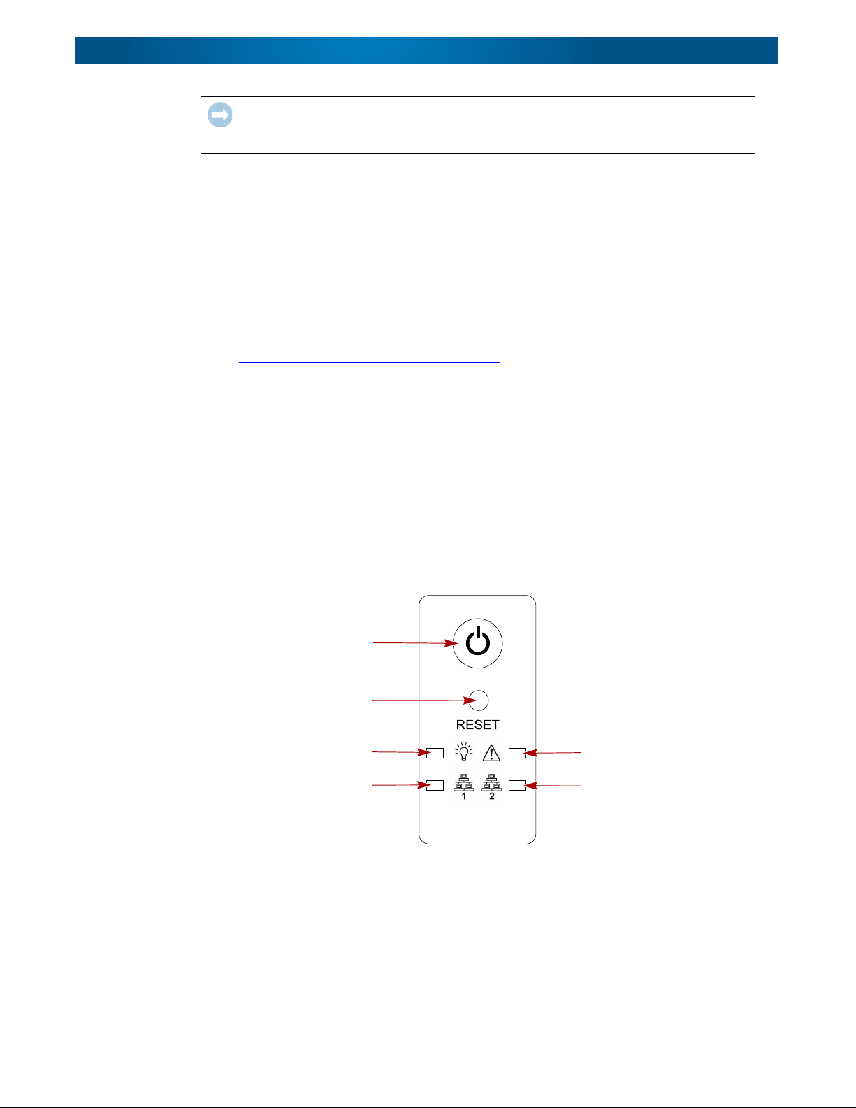
Power
Button
Reset
Access
Power
NIC 1
Activity
Alert
NIC 2
Activity
IMPORTANT: Before unpacking the unit, ensure that the area is free from conditions
that cause electrostatic discharge (ESD). Discharge static electricity from your body by
touching a known grounded surface. Also, avoid touching pins, leads, or circuitry.
Using the SnapSAN S2000 Quick Install Guide that came in the Accessory Kit, install
the unit in the rack as follows:
1. Install the Rail Kit in a RETMA rack.
2. Insert the SnapSAN S2000 into the rack.
3. Connect the network and data cables.
4. Attach the power cords.
NOTE: A PDF of the Quick Start Guide is available on the Overland Storage web site:
http://docs.overlandstorage.com/snapsan
Powering Up the SnapSAN S2000
The power switch is on the front panel located on the left side bracket. To turn the
appliance ON, press and hold the Power button for no more than one (1) second to
begin the power-up sequence.
After you turn the power ON, the System performs a self-test process, which takes a
couple of minutes.
After the unit completes the POST sequence, check the LED indicators on the left
bracket to verify the network connections are good.
10400277-004 07/2011 ©2010-11 Overland Storage, Inc. W 2-3
Page 16

CHAPTER
Initial Configuration
3
After installing a new SnapSAN S2000 appliance, there are two ways to handle the
initial configuration of an appliance:
• A Windows program (Windows SnapSAN Manager) is installed as part of the
SnapSAN Manager Suite on a network computer and can be used to configure
any SnapSAN S2000 appliance on the network (“
Manager”). This is the recommended procedure.
• The web interface (Web Management Interface) can be accessed by a browser to
configure and operate that specific appliance (“
Interface” on page 3-10). This can be used by any OS such as Linux or Mac.
Using the Windows SnapSAN Manager
Using the Windows SnapSAN
Using the Web Management
Before you can use the Windows SnapSAN Manager, you must make sure an iSCSI
initiator is installed on each Windows host and the SnapSAN Manager Suite software
has been installed.
Installing an iSCSI Initiator
An iSCSI initiator must be installed on each Windows host to access the storage
managed by the Windows SnapSAN Manager.
Windows Server 2003 and XP operating systems do not include an iSCSI initiator as
standard, but the Microsoft iSCSI initiator is available as a free download. To find the
initiator, go to http://www.microsoft.com/downloads
installation instructions that come with the initiator.
If you plan to use a different initiator, follow the instructions provided with it.
Installing SnapSAN Manager Suite Software
NOTE: The SnapSAN Manager Suite software can only be installed by the Administrator or a
user with Administrator privileges.
The SnapSAN S2000 SnapSAN Manager Suite files along with electronic copies of all
the important documents are available from download from the Overland SnapSAN
website:
http://docs.overlandstorage.com/snapsan
and search for iSCSI. Follow the
10400277-004 07/2011 ©2010-11 Overland Storage, Inc. W 3-1
Page 17
SnapSAN S2000 User Guide
The installation procedure automatically configures the Windows Firewall to allow
Windows SnapSAN Manager and its Appliance Discovery Service to access TCP and
UDP port 4309 on your computer. If you are using SnapServer Manager (SSM), it
configures access to TCP and UDP port 111.
outgoing access on this port. If your system is behind a NAT interface, you will have to set up
port forwarding to your computer for this port.
NOTE: To install the SnapSAN Manager Suite on a VMware vSphere Client, refer to
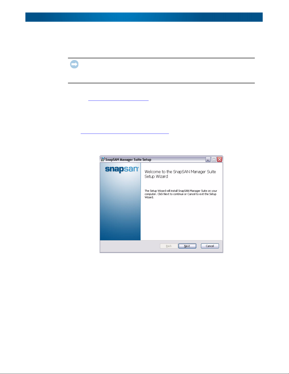
Follow the on-window instructions to install the software:
1. Download the appropriate version of the SnapSAN Manager.
2. Double-click setup.exe.
3. At the start window, click Next.
IMPORTANT: If you are using another firewall, open the firewall manually to allow the
Appliance Discovery Service and the Windows SnapSAN Manager incoming and
Appendix D, “
VMware Plug-In.”
Choose either the 32- or 64-bit version from:
http://docs.overlandstorage.com/snapsan
10400277-004 07/2011 ©2010-11 Overland Storage, Inc. W 3-2
Page 18
SnapSAN S2000 User Guide
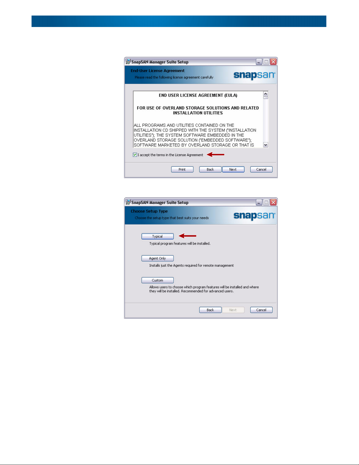
4. Review the license agreement, click the box to accept, and click Next to
5. At the Setup Type window, click Typical to continue.
continue the installation.
NOTE: The Typical option is recommended as the optimum configuration.
10400277-004 07/2011 ©2010-11 Overland Storage, Inc. W 3-3
Page 19
SnapSAN S2000 User Guide
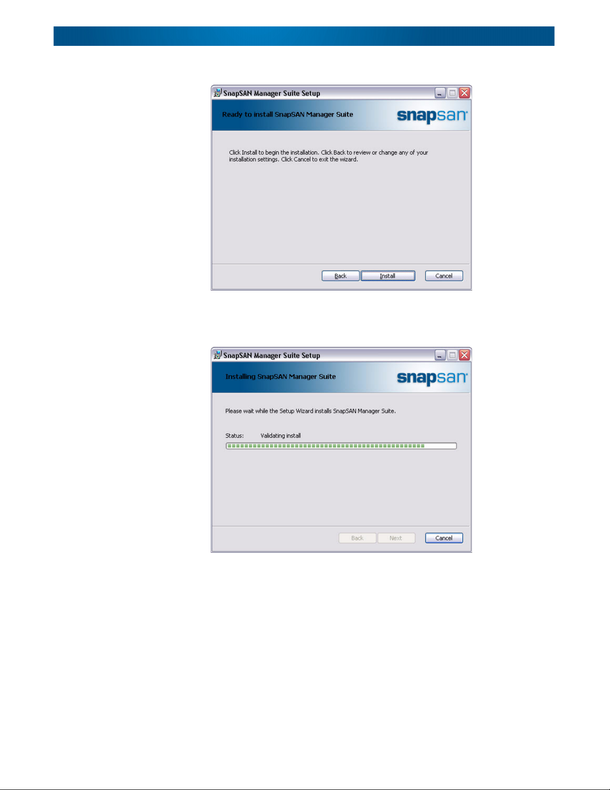
6. At the confirmation window, click Install.
The progress window is displayed with a Status bar showing the amount
completed. It may take several minutes to complete the installation. When done,
the Next button becomes active.
7. When the installation is complete, click Next.
10400277-004 07/2011 ©2010-11 Overland Storage, Inc. W 3-4
Page 20
SnapSAN S2000 User Guide
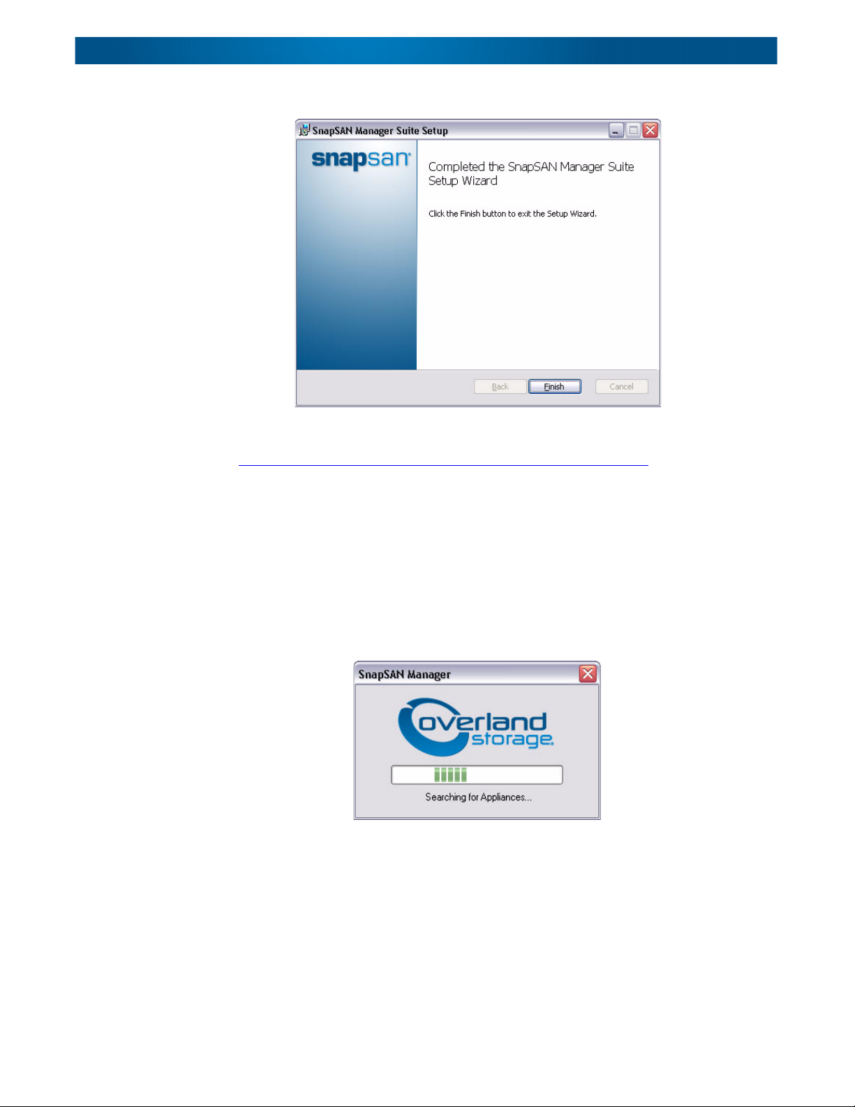
8. At the completion window, click Finish to exit.
Once the SnapSAN Manager Suite is installed and you click Finish, the program
automatically launches the Windows SnapSAN Manager. Continue with
“
Configuring the Appliance with Windows SnapSAN Manager.”
Configuring the Appliance with Windows SnapSAN Manager
To configure a SnapSAN S2000 appliance using Windows SnapSAN Manager:
1. If not already running, start the Windows SnapSAN Manager by selecting
Windows Start > All Programs > SnapSAN > SnapSAN Manager.
Automatically, Windows SnapSAN Manager tries to discover any appliances
that are connected to the network. During this discovery process, the Discovery
window is displayed and Windows SnapSAN Manager attempts to connect to
any SAN appliances it finds.
• If a connection succeeds, the SnapSAN Appliance Setup Wizard starts to
guide you through the setup process.
• If no appliances were discovered, the Windows SnapSAN Manager
Overview window will open. Recheck your network connections and verify
that the computer is on the same network as the SAN appliance.
10400277-004 07/2011 ©2010-11 Overland Storage, Inc. W 3-5
Page 21
SnapSAN S2000 User Guide
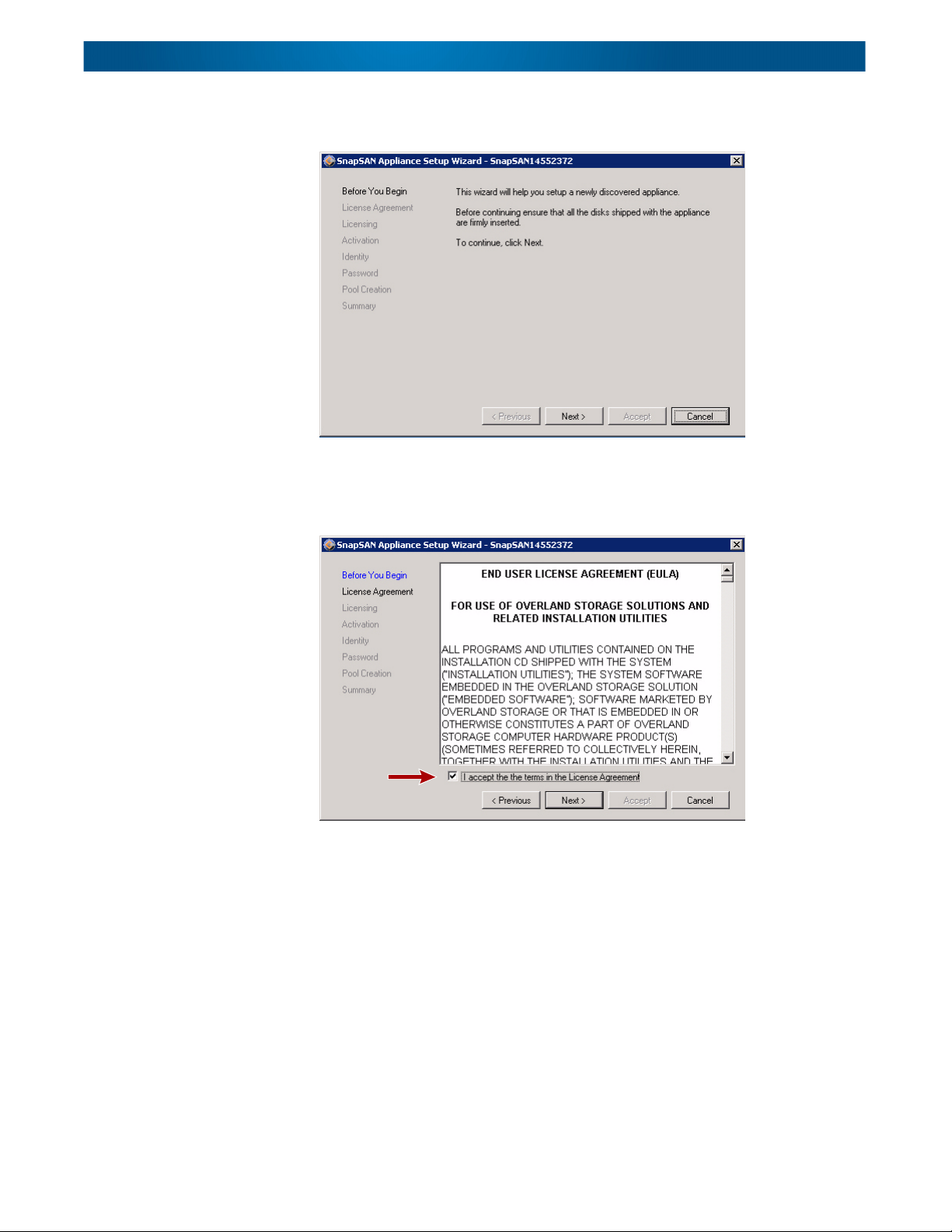
2. The SAN Appliance Setup Wizard Before You Begin page reminds you to check
3. At the EULA page, review the license agreement, click the box to accept, and
that the appliance’s disks are correctly inserted.
Once you have checked the disks, click Next to move to the next page.
click Next to continue the installation.
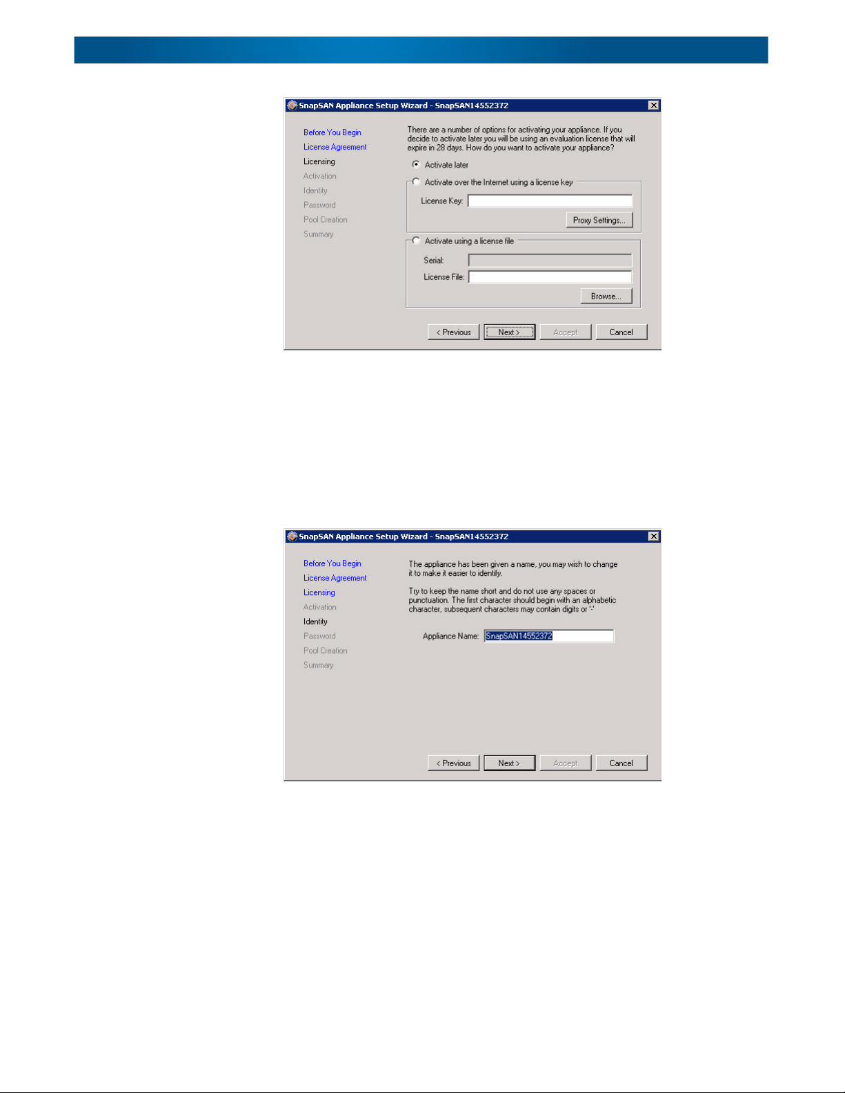
4. At the Licensing window, select one of the bulleted items:
• Activate later – use this option if the license key is not readily available.
• Activate over the Internet using a license key – use this option if you
have access to the Internet. Enter proxy settings if required.
• Activate using a license file – use this option to browse for the file with
both the license key and serial number. Does not require Internet access.
10400277-004 07/2011 ©2010-11 Overland Storage, Inc. W 3-6
Page 22
SnapSAN S2000 User Guide
5. At the Identity window, enter a new name if you want to rename the appliance,
If activating now, a second window (Activation) opens. Follow the onscreen
instructions to complete the activation. Click Next when done.
and click Next.
NOTE: We highly recommend changing the name to help identify the appliance on the
network. The name must start with a letter; subsequent characters can only be
letters, numbers, or hyphens.
10400277-004 07/2011 ©2010-11 Overland Storage, Inc. W 3-7
Page 23
SnapSAN S2000 User Guide
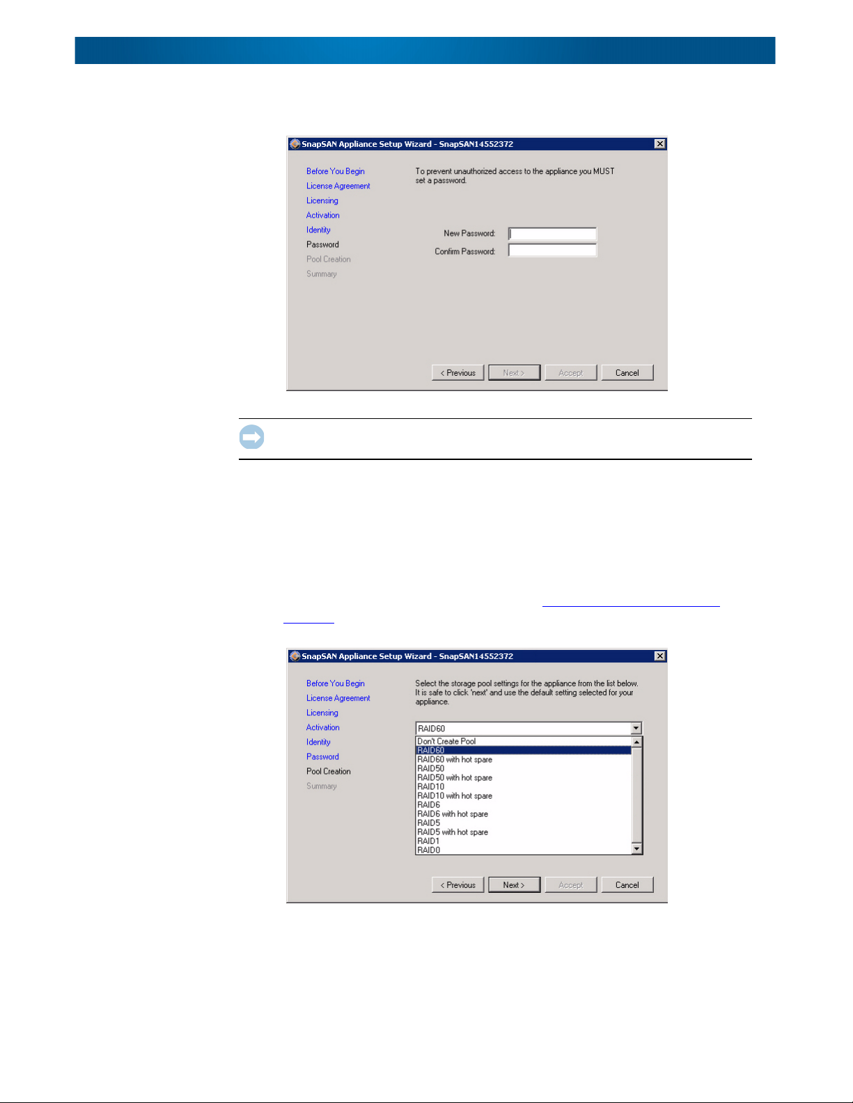
6. At the Password window, you must enter a password for the appliance, confirm
it by re-entering it, and then click Next.
IMPORTANT: Overland recommends using a strong password of at least six
alphanumeric characters.
7. At the Pool Creation page, select the type of RAID policy you want.
A pool represents the storage available on a set of disks managed by an
appliance. In effect, it comprises one or more of the physical disks connected to
the RAID controller, managed according to a management policy of your
selection. For the management policy you can specify either Typical or Custom.
NOTE: If you want to configure advanced RAID options, use the Windows SnapSAN
Manager to create the pool (as described in “
SnapSAN Pools Category” on
page 7-4) after the wizard has completed.
The options presented for Custom vary according to the number of physical
disks available and the type of RAID controller card:
• RAID 0 – Performance storage with no redundancy
• RAID 1 – Mirrored storage
10400277-004 07/2011 ©2010-11 Overland Storage, Inc. W 3-8
Page 24
SnapSAN S2000 User Guide
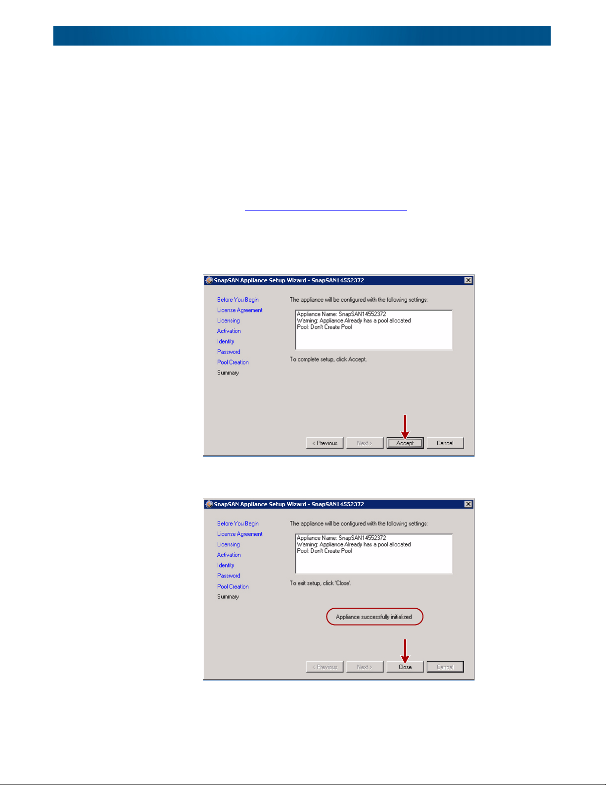
8. At the initial Summary page, review the settings you have made, and click
• RAID 5 – High availability storage (hot spare optional)
• RAID 6 – Very high availability storage (hot spare optional)
• RAID 10 – Multiple duplicated performance storage (hot spare optional)
• RAID 50 – Multiple high availability storage (hot spare optional)
• RAID 60 – Multiple very high availability storage (hot spare optional)
• Don’t Create Pool
NOTE: Select Don’t Create Pool if you want to create multiple pools or to create a
pool using only selected disks in the enclosure. After the wizard has
completed, use Windows SnapSAN Manager to create the pool as described
in see “
SnapSAN Pools Category” on page 7-4.
When you have finished configuring a storage pool, click Next.
Accept to configure the appliance.
9. At the secondary Summary page, verify the successful initialization, and click
Close to quit the SAN Appliance Setup Wizard.
10400277-004 07/2011 ©2010-11 Overland Storage, Inc. W 3-9
Page 25

SnapSAN S2000 User Guide
When the wizard finishes, the initial (default) Windows SnapSAN Manager window is
displayed showing the new volumes on the S2000 (such as “DSK1_VOL4”).
Chapter 4, “
SnapSAN Manager and also how to set up and manage the SAN.
These other chapters cover specific manager features in more detail:
• Chapter 5, “
• Chapter 6, “Network Management”
• Chapter 7, “Appliance Management”
Storage Management,” describes in general how to use Windows
PC and Servers Management”
Using the Web Management Interface
The web interface to the appliance, Web Management Interface, supports most
common web browsers, including Internet Explorer 7 or 8, and Firefox 3.5. JavaScript
must be enabled in the browser.
To use the built-in Web Management Interface to configure a specific SAN appliance,
it is necessary to know either the network name or network address (the IP
address) of the appliance. To find these, do one of the following:
• If you are not running a DHCP server, connect a keyboard and monitor to the
appliance so that you can assign a network address to it as described in
“
Assigning a Static Network Address” on page 3-11.
• If you are running a DHCP server on the network, find the network address of
the appliance as described in “
page 3-12.
Finding the DHCP Network Address” on
IMPORTANT: If your DHCP server supports reservations, reserve an IP address
for the appliance.
10400277-004 07/2011 ©2010-11 Overland Storage, Inc. W 3-10
Page 26
SnapSAN S2000 User Guide
Network Name
IP Address
Network
Interfaces
Enter Password
Assigning a Static Network Address
As shipped, the appliance is configured to get its network address using DHCP. If you
are not running a DHCP server, manually set the network address as follows:
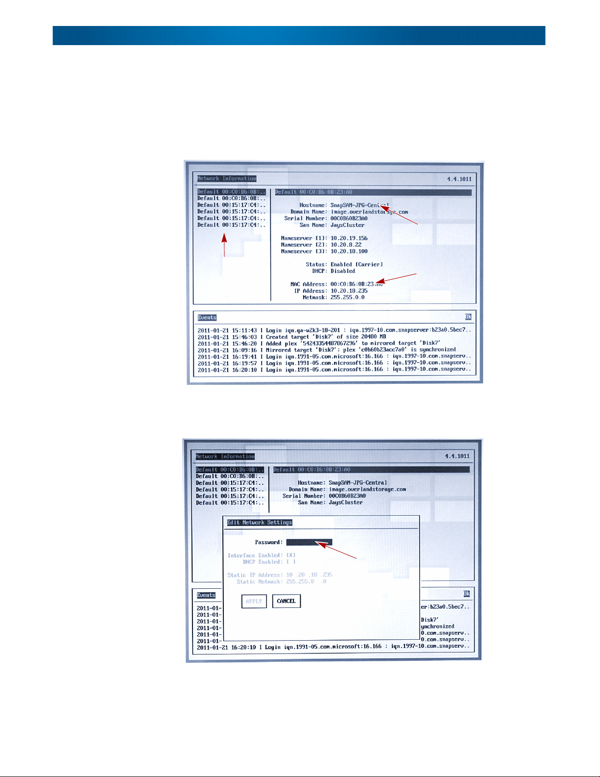
1. Connect a monitor and keyboard to the appliance.
The monitor will display the appliance’s Network Information window. This
gives the status of each network interface.
2. If necessary, use the Up and Down arrow keys to highlight the correct network
interface on the left, and press Enter.
The Edit Network Settings dialog box is then displayed.
3. Enter the appliance’s password.
NOTE: For an unconfigured system, “password” is the default preset.
10400277-004 07/2011 ©2010-11 Overland Storage, Inc. W 3-11
Page 27
SnapSAN S2000 User Guide
IP Address
Network Name
4. Using Tab or the Up and Down arrow keys, move to the DHCP Enabled field,
5. Enter the Static IP Address and Static Netmask for the appliance in the
6. Apply the changes by moving to the Apply box and pressing Enter.
7. Press Esc to quit.
and press Enter to disable DHCP.
appropriate fields.
To quit without applying the changes, move to the Cancel box and Enter.
Continue with “
Configuring the Appliance” on page 3-13.
Finding the DHCP Network Address
You can find the DHCP network address by direct connection to the appliance or using
the DHCP table.
Appliance Monitor Display
Connect a monitor to the video port of the appliance to read the appliance’s network
name and IP address from the appliance information window.
The network name, in the format “SnapSANnnnnnn,” is shown near the top of the
window, and the IP address 192.168.1.140 is shown near the middle of the window.
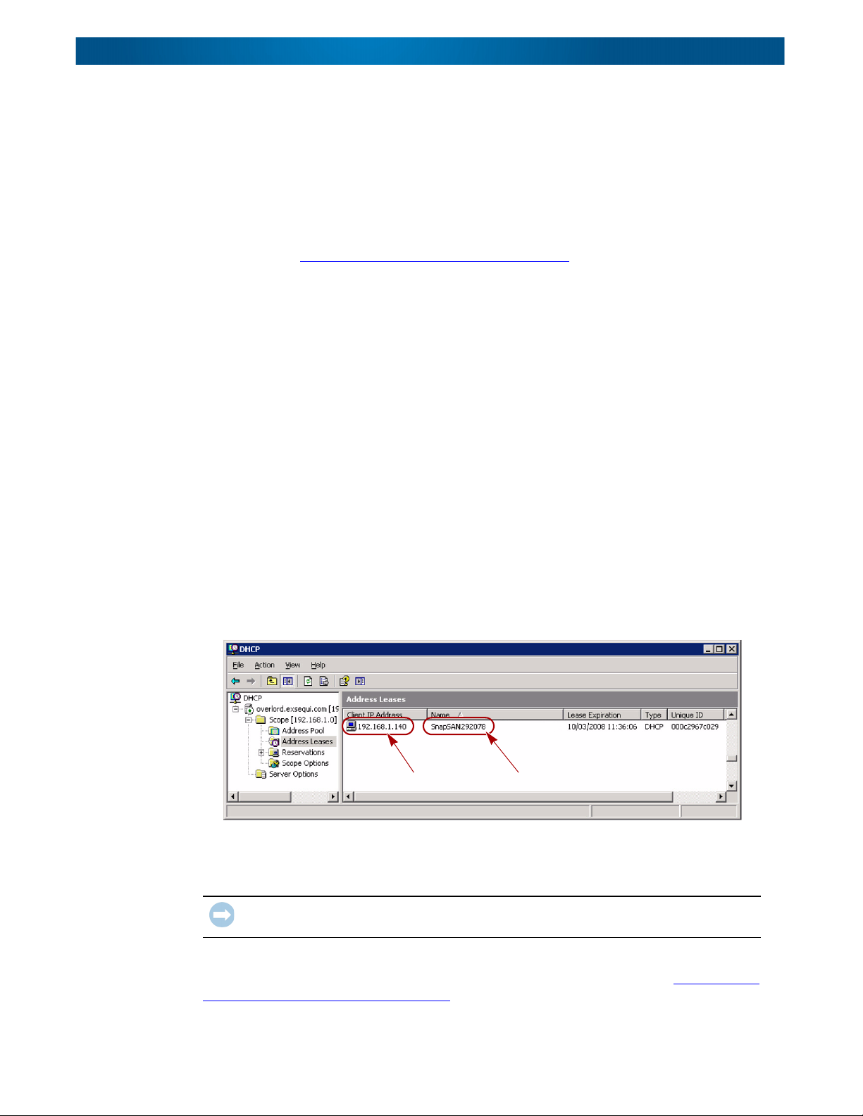
DHCP Server Client Table
Bring up your DHCP servers client table to read the appliance’s network name and IP
address. The details of doing this depend on the DHCP server being used. However,
there should be an option to display DHCP clients which have been allocated
addresses by the server.
For example, the client table for a Windows 2003 DHCP server:
Locate the entry with a name in the form “SnapSANnnnnnn” and note the name and
the IP address. When you configure the appliance, you can then change the network
name to something more memorable.
IMPORTANT: If your DHCP server supports reservations, reserve an IP address for the
appliance.
It is possible that some DHCP servers will not display network names. In this case,
use the appliance monitor display to get the information as described in “
Assigning a
Static Network Address” on page 3-11.
10400277-004 07/2011 ©2010-11 Overland Storage, Inc. W 3-12
Page 28
SnapSAN S2000 User Guide
Configuring the Appliance
To connect your web browser to the appliance, enter either the network name or the IP
address into your web browser. With some browsers, you may need to prefix the name
with “https://” (for example, “https://192.168.1.140”). When you configure the
appliance, you can change the network name to something more memorable if you
plan to use it for connection.
To configure your SnapSAN S2000 appliance using the Web Management Interface:
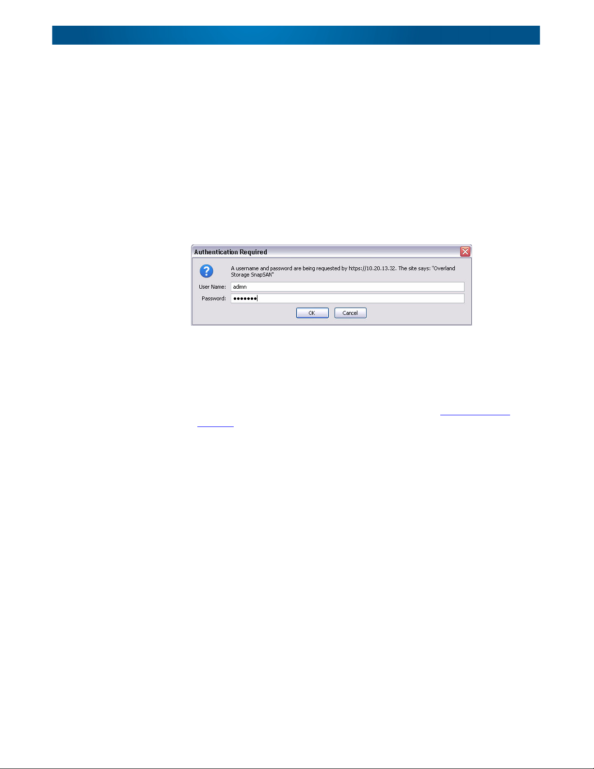
1. Open the Web Management Interface:
a. Enter the network name or IP address of the appliance into the browser
(with some browsers, you may need to preface the name with “http://”).
b. At the login dialog box, enter “admin” for the User Name and “password”
for the Password (you can change this later), and click OK.
NOTE: You may see a warning saying the web site is not trusted and asking you to
confirm whether you want to visit it. You can prevent this happening in future by
downloading the appliance’s security certificate and installing it in your browser.
In order for your browser to trust the secure connection to your SnapSAN S2000
appliance permanently, the CA certificate must be installed in your browser. A
link to the certificate can be found on the System page (see“
System Tab” on
page 8-3).
Installation of the certificate varies according to the browser you are using. With
some browsers, you can simply click the certificate and it will be installed
automatically; on others, you may have to save the certificate and then import it
into the browser, for example, by dragging it to the browser. After installing the
certificate, some browsers may have to be restarted for the connection to
become trusted.
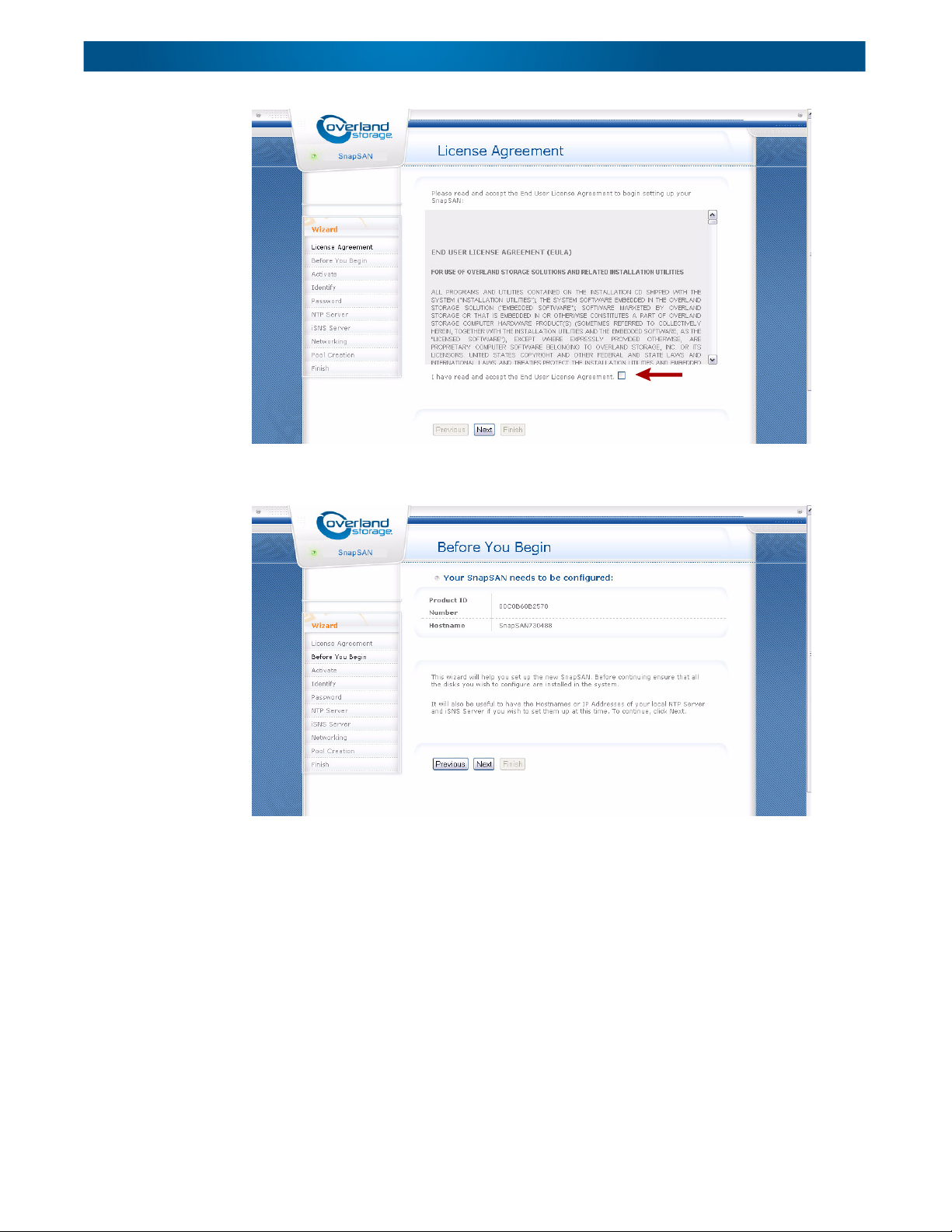
2. At the License Agreement page, read the license agreement, check the
Agreement box to accept it, and click Next.
If you do not accept the license agreement, you will not be able to proceed.
10400277-004 07/2011 ©2010-11 Overland Storage, Inc. W 3-13
Page 29
SnapSAN S2000 User Guide
3. At the Before You Begin window, the appliance’s serial number and current
Hostname are displayed. To start configuring the appliance, click Next.
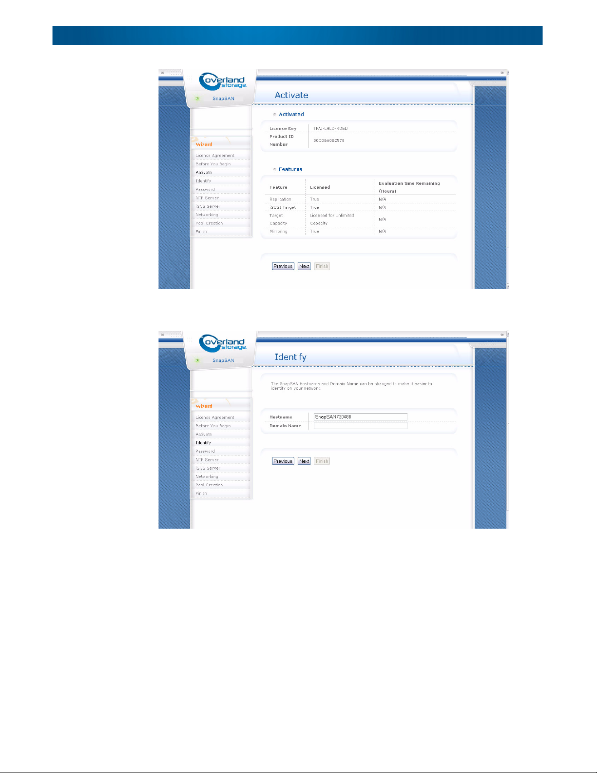
4. At the Activate page, review the activated settings for the appliance and click
Next.
10400277-004 07/2011 ©2010-11 Overland Storage, Inc. W 3-14
Page 30
SnapSAN S2000 User Guide
5. Enter the appliance’s network name (also known as the hostname) in the
Identify window, and click Next.
Optionally, you can enter your local network’s Domain Name. The network
name must start with a character (a-z, A-Z), use alphanumeric characters or a
dash (-) character, and must not include any spaces. If you do not supply a
domain name but want to specify an NTP or iSNS server name later, you will
have to supply the fully qualified domain name of the server.
6. At the Password page, change the Administrator Password from its default
value. For security reasons, you must enter a new password. Click Next to
continue.
10400277-004 07/2011 ©2010-11 Overland Storage, Inc. W 3-15
Page 31

SnapSAN S2000 User Guide
7. At the NTP Server page, select the option you want concerning the use of a
Network Time Protocol (NTP) server, and click Next.
An NTP server ensures that the system time on the appliance remains
synchronized with any other systems using an NTP server. If you have your own
NTP server, enter its details here. Alternatively, you could specify a public
server, for example pool.ntp.org, which is a pool of publicly accessible NTP
servers.
10400277-004 07/2011 ©2010-11 Overland Storage, Inc. W 3-16
Page 32

SnapSAN S2000 User Guide
8. At the iSNS Server page, specify an Internet Storage Name Service (iSNS)
server, and click Next.
The iSNS protocol aids the discovery of iSCSI hosts and targets. It is part of the
iSCSI protocol suite. The most widely used iSNS server is available free from
Microsoft (see http://www.microsoft.com/downloads
). If you have your own iSNS
server, enter its details at this screen.
9. The Networking page displays the default network configuration for the
appliance. Since there is nothing to change here, click Next to continue.
The two Ethernet ports on the appliance can be configured later for iSCSI
traffic, management traffic, or both.
NOTE: The page is for information only. You can alter the networking configuration later
using the Network page (see “
Network Tab” on page 8-11).
10400277-004 07/2011 ©2010-11 Overland Storage, Inc. W 3-17
Page 33

SnapSAN S2000 User Guide
10. At the Pool Creation page, configure your storage and create a storage pool,
and then click Next.
A choice of storage types is available, depending on the number of physical disks
present in the system and on whether you have a hardware RAID controller
installed. The storage types include:
• RAID 0 – Performance storage with no redundancy
• RAID 1 – Duplicated storage (on redundant disk)
• RAID 5 – High availability storage
• RAID 6 – Very high availability storage
• RAID 10 – Multiple duplicated performance storage
• RAID 50 – Multiple high availability performance storage
• RAID 60 – Multiple very high availability performance storage
NOTE: If you want to create multiple pools or to create a pool using only selected disks
in the enclosure, do not select any of the options. After the wizard has
completed, use Windows SnapSAN Manager (“
SnapSAN Pools Category” on
page 7-4) or the Pool Creation page (see “Create Storage Pool” on page 8-50) to
create the pool later.
11. The Initial Configuration Wizard displays the Finish page, click Finish to
confirm your settings.
The wizard will configure the appliance and create any requested storage pools
and volumes.
10400277-004 07/2011 ©2010-11 Overland Storage, Inc. W 3-18
Page 34

SnapSAN S2000 User Guide
Click Home in the Tab bar to go to the appliance’s home page to see an overview of the
targets, pools, and devices available on the appliance.
NOTE: Chapter 8
describes how to use Web Management Interface.
10400277-004 07/2011 ©2010-11 Overland Storage, Inc. W 3-19
Page 35

CHAPTER
Storage Management
4
This chapter describes how to carry out the following basic storage management tasks
using the Windows SnapSAN Manager installed on a network computer that can
access the SnapSAN S2000.
• Overview of the Windows SnapSAN Manager (below)
• Creating a SnapSan disk (page 4-2
• Backing up data (page 4-4
)
Windows SnapSAN Manager Overview
The Windows SnapSAN Manager enables you to manage your data storage using a
Windows interface. When you start up the manager, you will see the Overview (or
default) window. This is also accessed by clicking the Home button.
)
10400277-004 07/2011 ©2010-11 Overland Storage, Inc. W 4-1
Page 36

SnapSAN S2000 User Guide
The window has a number of panels. The top panel contains buttons for moving
backwards and forwards and returning home to this Overview window. It also has a
text box that shows where you are in the hierarchy of windows. As the text box shows,
this Overview window is actually the PCs and Servers/<host_name>/Overview
window, where <host_name> is the name of the PC that is running the Windows
SnapSAN Manager and to which the appliance is connected.
The right side panel (or view) represents the storage area network (SAN) and shows
the objects that can be managed. The left side panel is organized as a number of lists.
You can focus on different parts of the network and carry out management tasks by
using the controls in the left side panel. The list contents alter dynamically to match
the objects selected in the right side panel. The lists are as follows:
• <place_name> Tasks – This list holds the controls for carrying out operations
• Other Places – This list holds the controls for switching focus between the
• Categories – This list holds the controls for switching between different views
• Details – In s ome views, when you select an object in the right side pane, details
on the objects in the right side panel.
network, the PCs and servers, and the appliances. It also has controls for moving
backwards through a hierarchy of windows.
of an object.
about it are displayed in this list.
The right side panel may display one or more buttons. The buttons mirror entries in
the task lists. Hyperlinks in the right side panel provide a quick method of moving to
related views.
At the bottom of the window is a status bar. This is used to provide feedback when, for
example, a task completes or the system status changes.
You can find detailed information about the objects in the Other Places list as follows:
• PCs and Servers – Chapter 5, “
configure and manage the storage of PCs and servers.
• SnapSAN S2000 Network – Chapter 6, “
to configure and manage the SnapSAN S2000 network as a whole.
• Appliances – Chapter 7, “
and manage SnapSAN S2000 storage appliances.
To start using Windows SnapSAN Manager for basic operations such as creating disks
and backing up data, continue with “
Creating a SnapSAN Disk
NOTE: Before you can create any iSCSI volumes, you must have one or more storage pools
from which volumes are allocated. If you did not set up a disk pool using the wizard,
you need to do so now (see “
PC and Servers Management,” describes how to
Network Management,” describes how
Appliance Management,” describes how to configure
Creating a SnapSAN Disk.”
SnapSAN Pools Category” on page 7-4).
To create a SnapSAN disk using a previously created disk pool, follow the steps below.
This creates a disk with default configuration settings. If you want to create a disk
with a site-specific configuration, check the Show advanced settings box and configure
the disk as described in “
1. From the Overview screen, select Create SnapSAN Disk from the PC and
Server Tasks list.
10400277-004 07/2011 ©2010-11 Overland Storage, Inc. W 4-2
Disk Create Advanced Settings” on page 5-5.
Page 37

SnapSAN S2000 User Guide
2. At the Disk Create dialog box, select your settings:
a. Select from the top drop-down list the SnapSAN pool you want to use for
the new disk. A description of the pool selected is given in the dialog box
together with a star rating for its performance characteristics. One star is
the lowest level and five stars are the highest level.
b. Enter the size of the disk and the unit of measurement. Default values are
preselected and the maximum amount of free space available is shown above
the entry boxes.
10400277-004 07/2011 ©2010-11 Overland Storage, Inc. W 4-3
Page 38

SnapSAN S2000 User Guide
3. Select OK to confirm your choices and close the dialog box.
An icon for the new disk appears in the lower panel of the Overview window. While
Windows SnapSAN Manager configures the disk, a progress bar is shown above the
disk’s icon. The disk is ready when the progress bar disappears.
c. Choose a Windows drive letter for the disk. By default, the next free drive
letter is chosen.
d. Verify that the Auto Extend Disk box is checked (default) if you would like
Windows SnapSAN Manager to extend the size of the disk automatically as
the disk fills up.
After the disk has been created, you can configure details of how Windows
SnapSAN Manager automatically extends the disk (see “
Extension Task” on page 5-12).
NOTE: If you have activated the optional mirroring, you cannot use the Auto Extend
Disk feature.
Configure Auto
To confirm that the new drive is present, you can open My Computer.
Backing Up Data
Your SnapSAN S2000 appliance provides multiple ways to back up your data
including snapshots, replicas, and mirroring.
Using Snapshots
The snapshot has become an essential component of a modern data storage solution. It
provides a mechanism by which an (apparently) instantaneous copy can be taken of a
storage volume or disk. Snapshots were originally developed to overcome the problem
of volumes changing while backups were in progress. Snapshot technology allows the
10400277-004 07/2011 ©2010-11 Overland Storage, Inc. W 4-4
Page 39

SnapSAN S2000 User Guide
backup application to work with a snapshot of the volume, effectively corresponding to
the state of the volume at a single point in time. Typically the backup application
would create a volume snapshot, back up the snapshot and then delete it.
For efficient backup, SnapSAN S2000 software provides support for up to 256
Windows snapshots which are read-only. Technically speaking, Windows SnapSAN
Manager acts as a hardware provider in the Windows Volume Shadow Copy Service
(VSS) framework.
In response to requests from third-party VSS-compliant backup software, Windows
SnapSAN Manager provides a snapshot on the appliance of the data to be backed up.
A Windows VSS snapshot is effectively a temporary clone of the data. The backup
application then accesses the snapshot through the VSS interface to create a backup of
the data. When the backup is complete, the backup software notifies Windows
SnapSAN Manager that it has finished with the snapshot so that Windows SnapSAN
Manager can delete it. Sufficient space must be available on the appliance to hold the
snapshot for the backup to proceed.
The big advantage of using snapshots for backups is that users can continue to use the
system throughout the backup procedure. Another advantage is that administrators
can have “application consistent” backups using snapshots.
Using Replicas
NOTE: Replication is an add-on feature to the SnapSAN S2000 and requires a separately
purchased license.
A replica is a copy of a disk that is usually stored in a separate location from the
original. This location may be a different subsystem on the local area network or a
remote location connected by a wide area network. Whereas a snapshot provides a
one-off backup of a disk, a replica can be updated automatically at user-defined
intervals or on demand. Each update provides a recovery point. The state of the disk at
a recovery point can be recreated as a new disk. The recreated disk is known as a
mapped storage replica or, more simply, as a mapping. The update uses the VSS
service to ensure that the data is in a consistent state before it is replicated. As with
snapshots, users can continue to work while the replication takes place.
When a storage disk is created, a replica can be configured at the same time. To
replicate an existing storage disk, the entire contents of the original disk must be
transferred to the replica first. While not be feasible in all cases, the SnapSAN S2000
also supports the export and import of replicas on transportable media, such as a USB
disk (“
Export to USB Devices” on page 8-45). Once the data has been imported, the
replica can be updated over the network.
A replica can be removed if it is no longer required—the original disk is unaffected.
Similarly, a replica can be broken away from the original so that it exists in its own
right and is no longer updated when the original changes.
IMPORTANT: To enable replication, a replication storage journal must be configured
using the Web Management Interface. See “
Storage Journal Configuration” on
page 8-52 for details. The Replication Link, the interface over which the replication takes
place, is the first interface listed on the Network page.
Choose from these options:
• To replicate a new storage disk, follow the instructions below (“
Creating and
Replicating a New Disk Simultaneously”).
10400277-004 07/2011 ©2010-11 Overland Storage, Inc. W 4-5
Page 40

SnapSAN S2000 User Guide
• To replicate an existing storage disk over the network, follow the instructions
• To replicate an existing storage disk using export and import, follow the
• To schedule times for recovery points to be made, see “
• To set a recovery point, see “
• To recover data from a replica, see “
Creating and Replicating a New Disk Simultaneously
1. At the Overview screen, click Create SnapSAN Disk.
2. At the Disk Create screen, select your settings—but DON’T CLICK the OK
3. Check the Show Advanced Settings box to show the additional configuration
given in “
Replicate Disk Task” on page 5-12.
instructions in the Web Management Interface chapter “
page 8-65.
Properties & Scheduler
Category” on page 5-22.
Manage Disk Task” on page 5-10.
SnapSAN Replicas Category” on page 5-19.
button.
tabs.
Replicant Tab” on
10400277-004 07/2011 ©2010-11 Overland Storage, Inc. W 4-6
Page 41

SnapSAN S2000 User Guide
4. From the new tabs, select the Replication tab and configure:
Using Mirroring
As the primary volume changes, the replica must be updated. This update can be done
continuously, in which case the replica is called a mirror. With a mirror, every write
issued to the primary volume must be issued to the secondary mirror. Two forms of
mirroring are possible, synchronous and asynchronous.
a. Check the Create Replica check box to enable replication.
b. Choose a Storage pool from the drop-down list.
The tab shows the redundancy and speed ratings for the pool you select
together with both the amount of free space available and required.
c. To set up a schedule for updating the replica, select a Schedule from the
drop-down list at the bottom of the tab.
You can add or change the schedule later using the Properties & Scheduler
view, as described in “
“
SnapSAN Replicas Category” on page 5-19 for details about managing a
Properties & Scheduler Category” on page 5-22. See
replica.
5. Select OK to confirm your choices and close the dialog box.
An icon for the new replicated disk appears in the lower panel of the view. While
Windows SnapSAN Manager configures the disk, a progress bar is shown above
the disk’s icon. The disk is ready when the progress bar disappears.
6. Select the disk and then select Manage Disk from the PC and Server Tasks
list.
The Properties view confirms that the disk is being replicated. See “
Replication
Category” on page 5-16 for information on managing a replicated disk.
NOTE: N-way (or symmetric multiprocessing) mirroring is not supported.
10400277-004 07/2011 ©2010-11 Overland Storage, Inc. W 4-7
Page 42

SnapSAN S2000 User Guide
Synchronous Mirroring
With synchronous mirroring, a write to the mirrored volume is not acknowledged back
to the initiating host until the data has been written to both the primary volume and
to the secondary mirror. This guarantees that both primary volume and mirror
contain identical data, and in the event of the primary volume failing, the host can fail
over to the mirror without any interruption in service. However, unless the connection
between host and the primary volume and the primary volume and the mirror have
similar performance characteristics significant write latencies will be introduced. This
will typically lead to unacceptable write performance for the mirrored volume.
For this reason, synchronous mirroring is generally only feasible between systems
connected with a high performance, low latency link. This requires that the systems be
located physically quite close, and so synchronous mirroring is not usually appropriate
for disaster recovery when the replica is kept at a geographically remote site.
Asynchronous Mirroring
Asynchronous mirroring allows writes to the secondary mirror to be performed
asynchronously. The write operation can be acknowledged back to the initiating host
as soon as it has been written to the primary volume. Typically it will be buffered on
the primary controller and then written out in the background to the remote
secondary volume. This means that the connection between the primary volume and
the plex can be of a lower performance and that it can be used as a disaster recovery
solution between geographically remote systems.
However, because the update is asynchronous, it means that the secondary mirror is
usually a little out of date compared to the primary volume. This potential disparity
means that it cannot be used as a failover system, since if the host failed over, the
operating systems view of the volume and the actual contents of the volume would not
be quite the same. However, it should be possible to use the secondary volume by
restarting the host computer and having it perform a file system integrity check before
using the secondary volume as its primary volume. This is sometimes known as crashpoint consistency.
Unfortunately there are other problems with asynchronous mirroring. If there is a
failure, then the secondary mirror contains a version of the volume data as it was at an
essentially random point in time. It suffers from exactly the same problems as a
snapshot taken without using VSS, in that the data may not be self consistent as far
as applications are concerned.
Creating and Mirroring a New Disk Simultaneously
NOTE: MPIO software and a Neutral Storage Host are required for mirroring.
1. At the Overview screen, click Create SnapSAN S2000 Disk.
2. At the Disk Create screen, select your settings—but DON’T CLICK the OK
button.
IMPORTANT: The Auto Extend check box on the General tab page must be
UNCHECKED.
3. Check the Show Advanced Settings box to show the additional configuration
tabs.
10400277-004 07/2011 ©2010-11 Overland Storage, Inc. W 4-8
Page 43

SnapSAN S2000 User Guide
4. From the new tabs, select the Mirroring tab and configure:
a. Check the Create Mirror check box to enable mirroring.
b. Choose a Storage pool from the drop-down list.
The tab shows the redundancy and speed ratings for the pool you select
together with both the amount of free space available and required.
c. If a Neutral Storage Host has not yet been created, choose one from the
drop-down list at the bottom of the tab.
This option is not visible if a host has already been selected.
5. At the MPIO Path Status message, click OK start the process.
An icon for the new SAN disk appears in the lower panel of the content area.
While Windows SnapSAN Manager configures the disk, a progress bar is shown
above the disk’s icon. The disk is ready when the progress bar disappears.
6. Select the disk and then select Manage Disk from the PC and Server Tasks
list.
The Properties view confirms that the disk is being mirrored.
10400277-004 07/2011 ©2010-11 Overland Storage, Inc. W 4-9
Page 44

CHAPTER
5
Introduction
PC and Servers Management
This chapter describes the tasks you can carry out on PCs and servers using the
Windows SnapSAN Manager application.
• An introduction to PC and server management (below)
• How to create a SAN disk (page 5-4
• How to extend a SAN disk (page 5-10)
• How to destroy (remove) a SAN disk (page 5-9
• Managing a specific SAN disk including replication (page 5-10
)
)
)
By selecting PCs and Servers from the Other Places list on the Home screen, the PCs
and Servers screen is shown. Use this screen to select the PC computer or server you
want to configure or manage.
10400277-004 07/2011 ©2010-11 Overland Storage, Inc. W 5-1
Page 45

SnapSAN S2000 User Guide
Overview Screen
To access the PCs and Servers Overview screen, do one of the following:
• Double-click an unlocked (blue) server icon.
This is the same as selecting the unlocked (blue) server icon and clicking the
Manage PC or Server option on the left.
• Double-click an locked (black) server icon, enter the User Name and Password,
and click OK. Then double-click (or select the Manage PC or Server option).
This is the same as selecting the locked (black) server icon and clicking the Login
to PC or Server option on the left.
NOTE: When done, use the Logout of PC or Server option on the left of the Home screen.
The Overview screen displays the storage options associated with this PC or managed
server.
PC and Server Tasks List
The PC and Server Tasks list presents different options depending on which item, if
any, is selected in the right pane:
• When no disks are selected, only the Create a SnapSAN Disk task (see
page 5-4
• When a local disk is selected, a new task called Manage Disk (see page 5-10
appears in the list.
10400277-004 07/2011 ©2010-11 Overland Storage, Inc. W 5-2
) is shown.
)
Page 46

SnapSAN S2000 User Guide
• When a SnapSAN disk, replica, or mirror is selected in the content area, two
more tasks appear:
• Destroy SnapSAN Disk (see page 5-9
• Extend SnapSAN Disk (see page 5-10
)
)
Categories List
Four options are available in the Categories list:
• SnapSAN Replicas (see page 5-19
)
• Overview (current screen)
• Properties & Scheduler (see page 5-22
• Queued and Completed Tasks (see page 5-23
10400277-004 07/2011 ©2010-11 Overland Storage, Inc. W 5-3
)
)
Page 47

SnapSAN S2000 User Guide
Create SnapSAN Disk
When you select Create SnapSAN Disk from the PC and Server Tasks list, the Disk
Create dialog box opens.
Choose the appropriate settings for your storage disk:
• Storage – From the drop-down list, select the storage pool you want to use for
the new disk. A description of the selected storage pool is shown together with a
star rating (one star for lowest; five stars for highest) for its performance
characteristics.
• Total Size – Specify the total size of the disk (default values are provided) and
choose the unit of measurement (GB or MB)
• Drive Letter – Choose a Windows drive letter for the storage disk. By default,
the next free drive letter is pre-chosen.
• Auto Extend Disk – Check this box if you would like Windows SnapSAN
Manager to extend the size of the disk automatically as the disk fills up. See
“
Configure Auto Extension Task” on page 5-12 for more information.
NOTE: This option cannot be used with replication or mirroring.
• Show Advanced Settings – Check this box to display tabs to set up additional
security features, disk replication, mirroring, disk partitioning, and multipath
connections. See “
Disk Create Advanced Settings” on page 5-5 for more details.
NOTE: Replication and mirroring require additional licenses.
When you click OK, the new disk icon appears in the view. A bar at the top of the disk
icon shows the progress as the Windows SnapSAN Manager prepares the new drive
for use.
10400277-004 07/2011 ©2010-11 Overland Storage, Inc. W 5-4
Page 48

SnapSAN S2000 User Guide
Windows SnapSAN Manager creates a volume on the appliance, assigns it an iSCSI
target, sets up discovery controls, and configures the Windows server so the iSCSI
subsystem can discover the disk. Then the Windows SnapSAN Manager logs into the
disk, partitions it, creates an NTFS file system on it using Quick Format, and assigns
it a drive letter. When this is complete, the progress bar disappears.
If you open up My Computer, you can confirm that the new drive is present and that it
can be accessed in the same way as a local drive.
NOTE: To do a full format that scans for bad sectors, you must use Windows Disk Manager.
Disk Create Advanced Settings
To modify the default configuration of the storage disk being created, check the Show
Advanced Settings box. This displays additional tabs based on licensed features:
• Security – Select the Security tab to set additional security options.
In the CRC / Checksum area, select the check boxes to enable support for data
digests and/or header digests.
In the CHAP Logon Information area, select the check box to enable CHAP
authentication. Enter a secret, either as a character string or a hexadecimal
string.
10400277-004 07/2011 ©2010-11 Overland Storage, Inc. W 5-5
Page 49

SnapSAN S2000 User Guide
• Replication (optional licensed feature) – If licensed, select the Replication tab
to configure a replica of the disk.
Click the Create Replica check box to enable replication and then choose a
storage pool for the replica from the drop-down list. The tab shows the
redundancy and speed ratings for the pool you select together with the amount
of free space available and the amount required.
To set up a schedule for updating the replica, select a schedule from the dropdown list at the bottom. A schedule can be added later, if preferred, using the
Properties & Scheduler view, as described on page 5-22
, which also contains
further information about managing a replica and using recovery points to
capture the state of the replica at specified times. Data can be restored from the
replica at a recovery point.
NOTE: You cannot select both replication and mirroring for a storage disk.
10400277-004 07/2011 ©2010-11 Overland Storage, Inc. W 5-6
Page 50

SnapSAN S2000 User Guide
• Mirroring (optional licensed feature) – If licensed, select the Mirroring tab to
configure a mirror of the replica on the disk.
NOTE: You cannot select both replication and mirroring for a storage disk.
• Partitioning – Select the Partitioning tab to specify how the disk should be
partitioned. The Partitioning tab displays the partitioning schemes available.
10400277-004 07/2011 ©2010-11 Overland Storage, Inc. W 5-7
Page 51

SnapSAN S2000 User Guide
• MPIO – Select the MPIO tab to set up multiple paths (multiple connections)
Select a partitioning scheme by clicking the button alongside it:
• MBR Legacy – The Master Boot Record scheme offers backwards
compatibility with the legacy PC standard, which is limited to 4 partitions,
each up to 2 terabytes in size.
• GPT – The GUID Partition Table scheme supports up to 128 partitions with
over 2 terabytes per partition.
between initiators and targets. Having multiple paths available for network
operations can enhance performance and improve reliability.
To use MPIO, choose one of the following methods of configuring the
connections:
• Automatic – All the paths between initiators and targets will be discovered
automatically and the connections between them set up.
• Manual – All the paths are displayed in the panel together with their status.
Select the paths you want to configure and check their connectivity by
clicking the Validate button.
10400277-004 07/2011 ©2010-11 Overland Storage, Inc. W 5-8
Page 52

SnapSAN S2000 User Guide
The figure following illustrates the dataflow between the applications running on the
host and the disks in the iSCSI appliance when multiple interfaces are being used.
Destroy SnapSAN Disk
To remove a selected storage disk, use the Destroy SnapSAN Disk option from the PCs
and Servers Tasks list. The Confirm SnapSAN Disk Destroy dialog box is shown
asking for confirmation with a warning that all data on the disk will be lost.
NOTE: All replicas and mirrors must be removed before a disk can be destroyed.
10400277-004 07/2011 ©2010-11 Overland Storage, Inc. W 5-9
Page 53

SnapSAN S2000 User Guide
Extend SnapSAN Disk
You can extend the size of a SnapSAN storage disk manually by selecting it in the
view and then selecting Extend SnapSAN Disk from the PC and Server Tasks list.
The Disk Extend dialog box is shown. Enter the new size of the disk and click OK.
Manage Disk Task
To manage a selected disk, select Manage Disk from the PC and Server Tasks list. The
Properties view of the disk is shown.
10400277-004 07/2011 ©2010-11 Overland Storage, Inc. W 5-10
Page 54

SnapSAN S2000 User Guide
The Disk Tasks list shows the management tasks you can perform on the disk:
Disk Tasks
• Rename Disk (see page 5-11
• Configure Auto Extend (see page 5-12
• Replicate Disk, if licensed and not mirrored (see page 5-12
• Mirror Disk, if licensed and not replicated (see page 5-12
)
)
)
)
The Categories list for Manage Disk provides the following views of the disk:
• Properties (current screen)
• Replication, if licensed (see page 5-15
• Mirroring, if licensed (see page 5-17
• Paths (see page 5-18
)
)
)
Up to four different tasks are available to manage a disk.
Rename Disk Task
To rename a highlighted disk, select Rename Disk from the PC and Server Tasks list.
The Disk Rename dialog box is displayed.
Enter a new name for the disk and click OK.
10400277-004 07/2011 ©2010-11 Overland Storage, Inc. W 5-11
Page 55

SnapSAN S2000 User Guide
Configure Auto Extension Task
To configure the automatic disk extension, select Configure Auto Extend from the
Disk Tasks list.
Use the dialog box to specify by what percentage the disk should be extended and what
minimum percentage of the disk should be kept free. You can also specify a maximum
size for the disk.
Replicate Disk Task
NOTE: Replication is an optional feature and requires a separate license.
To replicate a SnapSAN Disk, select the disk and then select Manage Disk from the
PC and Server Tasks list. The Properties view for the disk is displayed. Select
Replicate Disk from the Disk Tasks list to get the Replicate Disk dialog box.
IMPORTANT: To enable replication, a Replication Journal drive must first be configured
using the Web Management Interface. See “Pools Tab” on page 8-46 for details.
To replicate a previously created storage disk:
1. Select the newly created SnapSAN Disk in the content area to expand the
options in the PC and Server Tasks list.
2. Click Manage Disk in the PC and Server Tasks list.
10400277-004 07/2011 ©2010-11 Overland Storage, Inc. W 5-12
Page 56

SnapSAN S2000 User Guide
3. At the Manage Disk screen, click Replicate Disk.
4. Select the destination Storage.
The top panel shows details of the SnapSAN Disk to be replicated (the source).
The bottom panel shows details of the replica. Use the drop-down list to select a
storage pool where the replica will be created.
5. Click OK. A progress bar is displayed while the replica is being created.
Mirror Disk Task
NOTE: Mirroring is an optional feature and requires a separate license.
10400277-004 07/2011 ©2010-11 Overland Storage, Inc. W 5-13
Page 57

SnapSAN S2000 User Guide
To mirror a previously created storage disk:
1. Select the newly created SnapSAN Disk in the content area to expand the
2. Click Manage Disk in the PC and Server Tasks list.
3. At the SnapSAN Manage Disk screen, click Mirror Disk.
options in the PC and Server Tasks list.
10400277-004 07/2011 ©2010-11 Overland Storage, Inc. W 5-14
Page 58

SnapSAN S2000 User Guide
4. Select the destination Storage.
Categories
The top panel shows details of the SnapSAN Disk to be mirrored (source). The
bottom panel shows details of the mirror (destination). Use the drop-down list to
select a storage pool where the mirror will be created.
5. Click OK. A progress bar is displayed while the mirror is being created.
Four Category options are available under Manage Disk.
Properties
This is the default screen displayed when Manage Disk is clicked under the PCs and
Servers Overview screen. It displays the current information and status of the disk.
10400277-004 07/2011 ©2010-11 Overland Storage, Inc. W 5-15
Page 59

SnapSAN S2000 User Guide
Replication Category
Select Replication from the Categories list to manage a replicated disk. This view
displays the replicated disk and the storage available for replicas.
When the replicated disk is selected, two tasks are shown in the Disk Tasks list:
• Create Recovery Point – Enables you to add a new recovery point.
The Creating Recovery Point dialog box appears with a bar showing the progress
of the operation, which may take some time with a large disk. When the recovery
point has been created, it will be listed in the Properties view of the SnapSAN
Replica. (To get to the Properties view, select the replica destination in the view
and then Manage Replica Destination from the Disk Tasks list. Click the arrow
button to return to this Replication view.)
• Add Replica Destination – specifies an additional location for the replicated
data. Use this to create multiple replicas of the same data and increase
redundancy.
When a replica destination in selected, the Disk Tasks list changes to three tasks:
• Destroy Replica Destination – This deletes all the replicated data on this
replica and stops data being replicated to it. Other replicas, created using Add
Replica Destination, are not affected.
• Break Replica Destination – Select this task to stop the selected replica being
updated. The “replica” can be used as before: any recovery points associated with
it can be mapped and it remains accessible from the SnapSAN Replicas view of
PCs and Servers.
• Manage Replica Destination – This displays the Properties view of the
replica.
10400277-004 07/2011 ©2010-11 Overland Storage, Inc. W 5-16
Page 60

SnapSAN S2000 User Guide
Mirroring Category
Select Mirroring from the Categories list to manage your storage disks that are
mirrored. This view displays the mirrored disk and its plexes.
When either the mirrored disk or the Leader Plex is selected, one task is shown in the
Disk Tasks list:
• Add Plex – This option lets you create another plex of the mirror.
When a Plex is selected, Disk Tasks changes to show:
• Transfer Leadership to Plex – This switches the Plex to become the Leader
Plex of the mirror.
• Destroy Plex – Causes the Plex to be removed from the mirror and destroyed.
• Break Plex – Results in the Plex being broken away from the mirror. If this was
the only plex remaining with the mirror, the mirror is destroyed.
10400277-004 07/2011 ©2010-11 Overland Storage, Inc. W 5-17
Page 61

SnapSAN S2000 User Guide
Paths Category
Select Paths from the Categories list to set up multiple paths between the PC or server
(or more strictly, the initiator) and the selected disk (the target). This view displays
information about the status of the paths and enables you to add and remove paths.
See “
Disk Create Advanced Settings” on page 5-5 for more information on multiple
paths.
10400277-004 07/2011 ©2010-11 Overland Storage, Inc. W 5-18
Page 62

SnapSAN S2000 User Guide
SnapSAN Replicas Category
From the Home screen, click the SnapSAN Replicas category to view all the SnapSAN
replicas that have been created. If a replica is on the same SAN as the PC or server,
the drive letter and hostname of the replicated disk is displayed.
Select a replica to display the tasks in the SnapSAN Replicas list:
• Manage SnapSAN Replica – This displays the SnapSAN Replica Properties
view for the selected replica.
• Destroy SnapSAN Replica – A dialog box pops up for you to confirm the
destroy operation as it will delete all the replicated data. The original data (the
source of the replica) remains intact.
10400277-004 07/2011 ©2010-11 Overland Storage, Inc. W 5-19
Page 63

SnapSAN S2000 User Guide
SnapSAN Replica Properties Management
By selecting Manage SnapSAN Replica from the SnapSAN Replicas category default
screen, the SnapSAN Replica properties screen is displayed.
The calendar enables you to check whether any recovery points have been recorded on
a selected day. The recovery points for that date (shown on the calendar in bold text)
are listed in the box to the right. They correspond to scheduled updates to the replica
(set up using the Properties & Scheduler view) and one-off updates (created as
described in “
Manage Disk Task” on page 5-10).
NOTE: The scheduler for Replication is only used on Windows Systems. Scheduled
replication for any other OS is not supported through the scheduler. There is a utility,
called remote_replicate, which works with cron on Unix systems in order to add to a
schedule.
Using the Calendar to Recover Data
To recover the data from the replica at a given recovery point:
1. Highlight a date shown in bold type in the calendar (representing a day with a
recovery point).
2. Select a time from the list next to the calendar.
3. Click Create Disk.
4. In the Map Replica dialog box, select a location and create a name for the new
disk.
You can accept the default drive letter are choose one yourself.
5. Click OK.
10400277-004 07/2011 ©2010-11 Overland Storage, Inc. W 5-20
Page 64

SnapSAN S2000 User Guide
Disks that have been created in this way are known as mappings. Changes made to a
mapping do not affect the replicated disk or the replica. Similarly, changes to the
replicated disk (which are reflected in the replica) do not affect any mappings.
To view all the recovery points that have been mapped, select Recovery Point Disk
Mappings from the Categories list. The following figure shows a single mapping.
When you select a mapping, the available tasks are displayed in the SnapSAN Replica
Tasks list, as follows:
10400277-004 07/2011 ©2010-11 Overland Storage, Inc. W 5-21
Page 65

SnapSAN S2000 User Guide
• Destroy SnapSAN Disk – A dialog box pops up for you to confirm the destroy
operation as it will delete all the data on the mapping. This means that any
changes made to the mapping will be lost although the original mapping can be
created again from a recovery point.
• Manage SnapSAN Disk – This displays the SnapSAN Disk Properties view.
The only task available in the Disk Tasks list is renaming the disk, as described
in “
Rename Disk Task” on page 5-11. If the PC or server supports multiple
paths, select the Paths view from the Categories list to select the paths between
the initiator on the PC or server and the target controlling access to the disk.
Properties & Scheduler Category
From the Home screen, click Properties & Scheduler to display the name and IP
address of the PC or server.
The bottom table in the view lists any schedules that have been set up for the PC or
server. Click Add (or select Add Scheduled Task from the PC and Server Tasks list) to
add a scheduled item. The Scheduled Task Wizard dialog box is displayed for you to
enter details of the schedule.
NOTE: Scheduling of a replication pair using this tool is not available for LINUX. Refer to the
Overland Technical Support site and download the PDF for LINUX scheduling:
AppNote_S2000_LINUX_Remote_Replicate_Utility.pdf.
10400277-004 07/2011 ©2010-11 Overland Storage, Inc. W 5-22
Page 66

SnapSAN S2000 User Guide
NOTE: The scheduler for Replication is only used on Windows Systems. Scheduled
replication for any other OS is not supported through the scheduler. There is a utility,
called remote_replicate, which works with cron on Unix systems in order to add to a
schedule.
Queued and Completed Tasks Category
From the Home screen, click Queued and Completed Tasks to display two lists: one
displays a list of tasks that are queued, and the other displays a list of tasks that have
completed or failed. The most recent task is at the top of its list.
10400277-004 07/2011 ©2010-11 Overland Storage, Inc. W 5-23
Page 67

SnapSAN S2000 User Guide
Select a task and then either click the View button or select View Task from the PCs
and Server Tasks list to see the Task View window which gives more information
about the task.
To clear the tasks from the log, either click the Clear button under a list or select the
appropriate Clear All task option from the PCs and Server Tasks list.
10400277-004 07/2011 ©2010-11 Overland Storage, Inc. W 5-24
Page 68

CHAPTER
6
Network Management
This chapter describes the network management tasks you can carry out on the
storage area network using the Windows SnapSAN Manager.:
Overview
• Overview
• Setting Up Storage Groups
• Discovery process
• User Interface Preferences
• About page
Select the SnapSAN Network option from the Other Places list to access the
networking options. The SnapSAN Network Properties window is the default view.
of network management
10400277-004 07/2011 ©2010-11 Overland Storage, Inc. W 6-1
Page 69

SnapSAN S2000 User Guide
From this window, you can carry out the following network management tasks using
the Windows SnapSAN Manager:
• Grouping appliances together for ease of management (see below)
• Using the Discovery service to locate appliances in the network (see page 6-3
• Specifying user interface preferences (see page 6-5
• Checking details about the Windows SnapSAN Manager software (see page 6-6
Setting Up Storage Groups
The Windows SnapSAN Manager enables you to group appliances into one or more
domains for ease of management. Grouping is done by assigning SAN names to
appliances and then applying a SAN Filter that filters which appliances can be seen
according to their names. Assigning SAN names to appliances is described in
“
Properties Category” on page 7-34.
To configure a SAN filter, be sure SnapSAN Network is selected from the Other Places
list. At the Properties default window, click the Change button (or select the Change
SAN Filter task) to open the SAN Filter Option box. Select the option you want:
)
)
)
• The first bullet enables you to manage ALL unassigned appliances.
• The second bullet enables you to manage all the appliances in the SAN.
• The third bullet filters the appliances based on a specific name AND includes all
unnamed appliances.
• The fourth bullet filters the appliances based on a specific name.
For example, if you set the SAN Filter to Accounts using the third button, you will only
be able to see (and manage) storage assigned to the SAN-named Accounts and storage
with no SAN name assigned to it. If you select the last button, you will only be able to
manage storage assigned to the SAN-named Accounts.
10400277-004 07/2011 ©2010-11 Overland Storage, Inc. W 6-2
Page 70

SnapSAN S2000 User Guide
Discovery
The Windows SnapSAN Manager is set up to discover SnapSAN appliances on your
network automatically. Sometimes, however, when the network is complex (for
example, where there are multiple subnets) the discovery operation may have to be
configured manually. To do this, at the SnapSAN Network window, select Discovery
from the Categories list.
This view shows all the PCs, servers, and appliances discovered by the Windows
SnapSAN Manager. It displays their IP address, name, and unique serial number.
Each IP address entry is prefixed as follows to show its status:
• Green check indicates that the appliance can be contacted through the IP
address.
• Red cross indicates a connection problem.
• The letter S, written as a superscript, denotes a static entry (an IP address
entered by the user).
Check the Enable Automatic Rediscovery box at the bottom to enable Windows
SnapSAN Manager to periodically try to discover any new storage in the SAN. If you
clear the check box, discovery is only carried out when manually initiated.
Check the Enable Broadcast Discovery box to enable Windows SnapSAN Manager to
use broadcast addressing to discover any new storage in the SAN.
NOTE: Note that the discovery service is subject to any SAN filters that have been
configured as described in “
The SnapSAN Network Tasks list enables you to carry out the following tasks:
• Refresh the view with up-to-date information about the SAN.
• Add an entry to the SAN (see page 6-4
• Remove an entry from the SAN (see page 6-4
Setting Up Storage Groups” on page 6-2.
).
).
10400277-004 07/2011 ©2010-11 Overland Storage, Inc. W 6-3
Page 71

SnapSAN S2000 User Guide
Add Discovery Entry
Click the Add button (or select the Add Discovery Entry option from the tasks list) to
add an appliance, PC, or server to the SAN. The Add Discovery Entry dialog box pops
up for you to enter the IP address.
Entries that you add to the SAN in this way are referred to as static entries, those that
are discovered automatically are referred to as dynamic entries. The IP addresses for
dynamic entries may change over time. Static entries are differentiated from dynamic
entries in the Discovery view by a superscript S next to the address.
Remove Discovery Entry
To remove a static decommissioned appliance, PC, or server from the SAN, select its
entry from the static list, and then click the Remove button (or select the Remove
Discovery Entry option from the tasks list).
NOTE: If you try to remove a node which is physically present in the SAN, it will automatically
be discovered again and added back to the list if automatic rediscovery is enabled.
10400277-004 07/2011 ©2010-11 Overland Storage, Inc. W 6-4
Page 72

SnapSAN S2000 User Guide
User Interface Preferences
The Windows SnapSAN Manager user interface can be configured to ask for
confirmation before carrying out irreversible actions, such as destroying storage pools
or shutting down storage appliances. In the SnapSAN Network window, select the
Preferences view from the Categories list to set your preferences.
Check the boxes in the right side panel for the actions that you want to confirm. You
can restore the default settings by selecting Restore Defaults from the SnapSAN
Network Tasks list or by clicking the button.
CAUTION: The last four check boxes (debug options) are for use by Overland Technical
Support and should not be used without their direction.
10400277-004 07/2011 ©2010-11 Overland Storage, Inc. W 6-5
Page 73

SnapSAN S2000 User Guide
About
The About view displays the version of the Windows SnapSAN Manager and includes
a link to the SnapSAN appliance support web site. In the SnapSAN Network window,
select the About view from the Categories list
10400277-004 07/2011 ©2010-11 Overland Storage, Inc. W 6-6
Page 74

CHAPTER
7
Appliance Management
This chapter describes the appliance management tasks you can carry out on the
storage area network using the Windows SnapSAN Manager:
• O
verview of management options (includes Properties Category)
• Hard Disks
• SnapSAN Pools Category
• SnapSAN Targets Category
• SnapSAN Replicas Category
• Network Category
• Hardware Monitoring Category
• Events Category
• Identification & Services Category
• Initiators Category
• Notification Category
• Statistics Category
Category
Overview
To manage a SnapSAN S2000 appliance, select Appliances from the Other Places list.
From the Appliances view, highlight a SnapSAN S2000.
10400277-004 07/2011 ©2010-11 Overland Storage, Inc. W 7-1
Page 75

SnapSAN S2000 User Guide
If the appliance is locked (black and with a padlock on its icon), select Login to
Appliance from the Appliances list. Enter the password for the appliance in the
window that pops up.
NOTE: If a Warning icon appears with the appliance icon ( ), go to the “
Events Category”
view to determine what caused the problem.
To update the status of the appliance, select Refresh from the same list.
After logging back in, double-click the icon (or select Manage Appliance from the
Appliances tasks list) to display the default Properties view.
The entries in the Categories list enable you to manage the following aspects of the
appliance:
• Hard Disks
Category – Device management is carried out in the Hard Disks
view.
• SnapSAN
Pools Category – Pool management is carried out using the Pools
view.
• SnapSAN
Targets Category – Target management is carried out using the
Targets view.
• SnapSAN
Replicas Category – Replica management is carried out using the
Replicas view.
• Network
Category – Network management is carried out using the Network
view.
• P
roperties Category – System management tasks specific to an appliance are
carried out using the Properties view (current view).
• Hardware Monitoring
Category – Where the appliance hardware supports
monitoring, information such as voltages, fan speeds and temperatures are
displayed in the Hardware Monitoring view.
• Events
10400277-004 07/2011 ©2010-11 Overland Storage, Inc. W 7-2
Category – Event management is carried out using the Events view.
Page 76

SnapSAN S2000 User Guide
• Identification & Services Category– Configuring the domain name and password
of an appliance and the services that the appliance uses is carried out using the
Identification & Services view.
• Initiators
carried out using the Initiators view.
• Notification
when specified events take place is carried out using the Notification view.
• Statistics
using the Statistics view.
Category – Management of the initiators recognized by an appliance is
Category – Configuring the display of statistical data is carried out
Hard Disks Category
To display details of all of the physical disks in the appliance, select Hard Disks from
the Categories list. The view displays all the disks in the appliance. To display the
properties of a particular disk, select that disk and its basic properties are displayed in
a Details list on the left side.
Category – Configuring the appliance to send messages to personnel
10400277-004 07/2011 ©2010-11 Overland Storage, Inc. W 7-3
Page 77

SnapSAN S2000 User Guide
Select Manage Hard Disk from the Hard Disks list to see the detailed properties of a
selected disk.
The details include the device name, size, status, the pool to which the device is
assigned, whether it is in use, and whether it is acting as a hot spare (a redundant
disk for hot backup).
An unused disk can be designated as a Global Hot Spare if the RAID configuration
supports hot spares. A global hot spare will automatically replace an equivalent failed
disk in a pool that shares the same subsystem as the hot spare. See “
SnapSAN S2000 Pool” on page 7-6.
SnapSAN Pools Category
Before you can create any iSCSI volumes, you must create one or more storage pools
from which the volumes can be allocated. A SAN storage pool is a group of physical
disk drives, aggregated together using RAID.
NOTE: Storage pools may have already been created when the appliance was initially
configured.
Manage a
10400277-004 07/2011 ©2010-11 Overland Storage, Inc. W 7-4
Page 78

SnapSAN S2000 User Guide
To display the SAN pools created on an appliance, select SnapSAN Pools from the
Categories list on the Appliance Properties page. The existing pools are displayed.
Select a SAN pool to see basic information about it in the Details list on the left.
You can perform the following tasks on a pool using the entries in the SnapSAN S2000
Pools list:
• M
anage a SnapSAN S2000 Pool (see page 7-6)
• Extend a SnapSAN
• Destroy a SnapSAN
• Create a
SnapSAN Pool (see page 7-8)
Pool (see page 7-7)
Pool (see page 7-7)
10400277-004 07/2011 ©2010-11 Overland Storage, Inc. W 7-5
Page 79

SnapSAN S2000 User Guide
Manage a SnapSAN S2000 Pool
To manage a pool, select the pool and then double-click the icon (or select Manage
SnapSAN Pool from the SnapSAN Pools tasks list). This displays the Properties view
of the pool.
The view displays basic pool properties, such as the pool name, size, free space, size of
the replication journal (if present), RAID level, and state. If a disk fails, then a pool
with redundancy (RAID 1, 5, 6, 10, 50, or 60) will go into degraded mode. It will still be
accessible but performance may be reduced and it is vulnerable to loss of data if
another disk fails
1
.
This is also the window where the alarms are managed. You have an option of
disabling or muting an alarm in the SnapSAN Pool tasks list.
The table at the bottom of the view gives information on each target linked to the pool.
To see more information, double-click the disk’s entry in the table. This opens the
SnapSAN Targets Properties page.
1. Raid 1, 5, 10, or 50 can sustain a single disk failure without data loss; RAID 6 and 60 can sustain two
disk failures before loss occurs.
10400277-004 07/2011 ©2010-11 Overland Storage, Inc. W 7-6
Page 80

SnapSAN S2000 User Guide
To manage the devices in the pool, select the Devices view.
The Devices view displays all the disk drives which make up the pool together with
their state. The state of each device should be Online unless a disk has failed, in which
case the disk should be removed and replaced. The replacement disk should be added
as a hot spare. The hot spare will then automatically replace the failed disk.
The Failed Devices panel is only enabled if a disk has failed. It allows you to remove
the failed disk from its pool.
The Hot Spares panel allows you to dedicate a hot spare disk to a specific pool. A hot
spare is a disk which is normally unused except when a disk fails in a RAID 1, 5, 6, 10,
50, or 60 pool. If a disk failure takes place, the hot spare automatically replaces the
failed disk and the RAID pool is automatically rebuilt to include the new disk.
Extend a SnapSAN Pool
This option is available for the standard RAID levels of 0, 5, and 6. To extend a pool,
select a pool and then select Extend SnapSAN Pool from the SnapSAN Pools tasks list.
The Extend Pool dialog box pops up for you to select which devices you want to add to
the pool. To use this option, one or more disk drives must be in a ready to use state.
Destroy a SnapSAN Pool
CAUTION: If you have changed the preferences under the SAN Network to not show a
warning dialog before deleting a pool, the pool with be destroyed as soon as you click
the Destroy SAN Pool link.
10400277-004 07/2011 ©2010-11 Overland Storage, Inc. W 7-7
Page 81

SnapSAN S2000 User Guide
To destroy a pool, select it and then select Destroy SnapSAN Pool from the SnapSAN
Pools tasks list. If configured, the Confirm Pool Destroy dialog box pops up to get your
conformation before destroying the pool.
NOTE: A pool cannot be destroyed if it has targets associated with it. To remove a target,
see “
Create a SnapSAN Pool
NOTE: Having enough available disk space (free disks) is a prerequisite to performing
creating a new pool.
The following types of SnapSAN pools are supported on the SnapSAN S2000:
Type Description Number of Disks
RAID 0 Performance storage with no redundancy Minimum of 2
RAID 1 Duplicated performance storage Exactly 2
RAID 5 High availability storage Minimum of 3
RAID 6 Very high availability storage Minimum of 4
RAID 10 Multiple duplicated performance storage Minimum of 4
RAID 50 Multiple high availability storage Minimum of 6
RAID 60 Multiple very high availability storage Minimum of 8
To create a SnapSAN pool, select Create Storage Pool from the SnapSAN Pools tasks
list. The Pool Create window pops up.
Destroying A SnapSAN Target” on page 7-19.
10400277-004 07/2011 ©2010-11 Overland Storage, Inc. W 7-8
Page 82

SnapSAN S2000 User Guide
You can specify the following parameters for the pool:
• Name – The name of the pool can be anything you like, up to 32 alphanumeric
characters in length. It cannot be blank.
• Subsystem – Select the hardware RAID controller. Since the SnapSAN S2000
only has one, it is pre-selected.
• RAID Level – Select a RAID level. The levels offered will depend on the number
of unused disks in the appliance.
• Stripe Size – This parameter is only applicable to RAID levels 0, 5, 6, 10, 50,
and 60. It is specified in kilobytes. Different stripe sizes may give improved
performance with specific application software but in most cases the default
value will suffice.
• Devices – The Devices list displays all the disks that are not currently assigned
to pools. Add a disk to the new pool by checking its check box.
NOTE: For some RAID levels, there are restrictions on number of disks required to make the
pool:
RAID Level/Span Minimum No. of Disks
RAID 0 Minimum of 2
RAID 1 Must be 2
RAID 5 Minimum of 3
RAID 6 Minimum of 4
RAID 10 Minimum of 4
RAID 50 Minimum of 6
RAID 60 Minimum of 8
10400277-004 07/2011 ©2010-11 Overland Storage, Inc. W 7-9
Page 83

SnapSAN S2000 User Guide
IMPORTANT: If you use RAID 5, 6, 50, or 60, the pool must be initialized by the RAID
controller. This can take several hours, depending on the size of the disks. While the
pool is being initialized, it can be used but performance is reduced.
When the pool has completed initialization, the pool state, shown in the Details list, is
set to Normal.
SnapSAN Targets Category
The SnapSAN S2000 provides storage to host computers in the form of iSCSI volumes.
An iSCSI volume appears to the host computer just like a regular disk drive but with
several important differences:
• Volumes can be created and destroyed as storage requirements change.
• Volumes can be extended dynamically as capacity requirements grow.
• A volume can easily be reassigned to a different host system without having to
shut host systems down or to move any disks physically.
• A volume can be shared between multiple hosts.
1
Each volume has an iSCSI target associated with it. Windows SnapSAN Manager
makes it very easy to create iSCSI targets and assign them to Windows host systems
using the SnapSAN Target view.
1. Volume sharing usually requires additional software running on the host, for example, clustering
software.
10400277-004 07/2011 ©2010-11 Overland Storage, Inc. W 7-10
Page 84

SnapSAN S2000 User Guide
You can perform the following tasks on a target using the entries in the SnapSAN
Targets list:
• M
anaging A SnapSAN Target (see page 7-11)
• D
estroying A SnapSAN Target (see page 7-19)
• Creating A
SnapSAN Target (see page 7-20)
• Extending A
Managing A SnapSAN Target
To manage a target, select it and then select Manage SnapSAN Target from the
SnapSAN Targets tasks list. This displays the default Properties view.
SnapSAN Target (see page 7-22)
The SnapSAN Target Tasks list shows the tasks you can perform on the disk
depending on the type of disk:
• Replicate (see “
• Mirror (see “
Replicating a Target” on page 7-18)
Mirroring a Target” on page 7-18)
You can manage a target by using the views selected from the Categories list:
• The Properties
• The Security
Category view
Category view (page 7-12)
• The Portals view (page 7-14)
• The Statistics
• The Replication
view (page 7-15)
view (page 7-17)
Properties Category
The properties of a target shown in the Properties view include the following:
• Name – The name assigned to the target when it was created.
10400277-004 07/2011 ©2010-11 Overland Storage, Inc. W 7-11
Page 85

SnapSAN S2000 User Guide
• Size – The size of the target volume.
• Pool – The storage pool from which the target was created.
• Unique ID – A worldwide, unique indentifier (called an EUI64 indentifier).
• Auth Type – The authentication required for the target. This can be None or
• State – The current state of the disk.
• IQN – The IQN allocated automatically to the target.
Security Category
Use the Security view to configure security measures for the target. This includes
whether CHAP authentication is used and which host systems are allowed to access
the target.
This is sometimes used by host-based storage applications, such as multipathing
software.
CHAP.
Enable/Disable CHAP. CHAP authentication can be enabled or disabled by clicking
the button or selecting Enable CHAP / Disable CHAP from the SnapSAN Target Tasks
list. If CHAP is enabled, both the initiator and the target must share a secret that is
exchanged during the login process. The login will fail if the secret is incorrect.
Add ACL. To add a host to the ACL, click the Add button under the list (or select Add
ACL from the SnapSAN Target Tasks list). This displays a dialog box.
10400277-004 07/2011 ©2010-11 Overland Storage, Inc. W 7-12
Page 86

SnapSAN S2000 User Guide
Select the initiator you want to add from the drop-down list labeled IQN. The list
shows the IQNs of all the initiators known to the appliance. If the initiator you want to
add is not listed, you can add it using the Initiators view (see “
Initiators Category” on
page 7-40).
If CHAP is enabled, specify the target’s secret and, if you are using mutual CHAP, the
initiator’s secret. Secrets must be between 24 and 32 hexadecimal digits long. Click
the Format Secrets as ASCII box to use ASCII characters rather than hexadecimal
digits. ASCII secrets must be between 12 and 16 characters long. The secrets entered
in this dialog box must be the same as those entered for the initiator.
Edit ACL. To change the access type of an initiator and alter its CHAP secrets, select
its IQN from the ACL and then click the Edit button (or select Edit ACL from the
SnapSAN Target Tasks list.)
NOTE: Before changing the ACL for a target that is being managed by the local iSCSI
initiator, the initiator must be logged out. The ACL modification dialog box pops up to
warn you to save any data before continuing.
If the local initiator is listed in the target’s ACL, selecting Enable CHAP from the
SnapSAN Target Tasks list will log the initiator out of the target, automatically assign
a CHAP secret to the target, and log back into the target with that secret.
Remove ACL. To remove a selected initiator from the ACL, select its IQN from the
ACL and then click the Remove button (or select Remove ACL from the SnapSAN
Target Tasks list).
10400277-004 07/2011 ©2010-11 Overland Storage, Inc. W 7-13
Page 87

SnapSAN S2000 User Guide
Portals
The Portals view enables you to deny access to the target through one or more of the
target’s interfaces and to group interfaces together.
To do this, select an interface in the view and then click the Edit button (or select Edit
Target Portal from the SnapSAN Target Tasks list). This opens the Modify Portal
Group dialog box.
10400277-004 07/2011 ©2010-11 Overland Storage, Inc. W 7-14
Page 88

SnapSAN S2000 User Guide
Check the box to enable portal groups for the interface and enter a group number and
click OK. By default, a group number of 1 is used. Group numbers range from 0 to
65535. If the portal group is enabled, uncheck the box to disable it.
Statistics
The Statistics view enables to you to see configured statistical data in graphical form.
10400277-004 07/2011 ©2010-11 Overland Storage, Inc. W 7-15
Page 89

SnapSAN S2000 User Guide
Click the Configure button (or select Configure Statistics from the SnapSAN Target
Tasks list) to set up the graph. The Configure Target Statistics dialog box pops up.
Select between statistics showing total throughput and those showing a count of
read/write operations, together with the time period for which you would like to see
the statistics. Click OK to display the graph.
To update the graph, click the Refresh button (or select Refresh Statistics from the
SnapSAN Target Tasks list).
10400277-004 07/2011 ©2010-11 Overland Storage, Inc. W 7-16
Page 90

SnapSAN S2000 User Guide
Replication
The Replication view enables to you to manage a replicated target. The view displays
the replicated target and the storage used for the replica, referred to as a replica
destination.
The date and times shown below the target and the destination show when a recovery
point was last made. When the replicated disk is selected, two tasks are shown in the
SnapSAN Target Tasks list:
• Add Replica Appliance
Allows you to specify an additional location for the replicated data. Use this to
create multiple replicas of the same data and increase redundancy.
• Create Recovery Point
Enables you to add a new recovery point.
The Creating Recovery Point dialog box appears with a bar showing the progress
of the operation, which may take some time with a large target. When the
recovery point has been created, it will be listed in the Properties view of the
Storage Replica. (To get to this view, select the replica destination in the view
and then Manage Replica Destination from the Replica Tasks list. Click the
arrow button to return to this Replication view.)
When a replica destination in selected, the SnapSAN Target Tasks list changes to
three different tasks:
• Break Replica Appliance
Select this task to stop the selected replica from being updated. The replica can
be used as before—any recovery points associated with it can be mapped and it
remains accessible from the SnapSAN S2000 Replicas view of PCs and Servers if
it has a Windows letter associated with it, showing that it has been mounted as
a Windows drive (see “
Creating A SnapSAN Target” on page 7-20).
10400277-004 07/2011 ©2010-11 Overland Storage, Inc. W 7-17
Page 91

SnapSAN S2000 User Guide
• Manage Replica Appliance
• Destroy Replica Appliance
Replicating a Target
To replicate a target, select it and then select Add Replica Appliance from the
SnapSAN Target Tasks list. The Create Replica dialog box is displayed.
This displays the Properties view of the replica.
This deletes all the replicated data on this replica and stops data being
replicated to it. Other replicas, created using Add Replica Destination, are not
affected.
The top panel shows details of the SnapSAN Target to be replicated (the source). The
bottom panel shows details of the replica (the destination). Use the drop-down lists to
select the appliance and the storage pool where the replica will be created. Click OK.
A progress bar is displayed in the content area while the replica is being created.
IMPORTANT: To enable replication, a Replication Journal must be configured using the
Web Management Interface. See “Storage Journal Configuration” on page 8-52.
“
SnapSAN Replicas Category” on page 7-23 contains further information on managing
replicas.
Mirroring a Target
The Mirroring view enables to you manage the plexes. The view displays the mirrored
target and plexes.
10400277-004 07/2011 ©2010-11 Overland Storage, Inc. W 7-18
Page 92

SnapSAN S2000 User Guide
When either the target or Leader Plex is highlighted, the Add Plex option is shown in
the SnapSAN Target Tasks list. It opens a dialog box that lets you choose the
Appliance and pool where you want to create the plex.
When an existing plex is highlighted, two different options are shown:
• Transfer Leadership to Plex – this makes the selected plex the Leader Plex.
• Break Plex – this breaks the selected plex away from the Leader Plex
preventing any future updates.
Destroying A SnapSAN Target
To destroy a target, select it and then select Destroy SnapSAN Target from the
SnapSAN Targets tasks list. If configured, the Confirm SnapSAN Target Destroy
dialog box appears for confirmation before destroying the target.
10400277-004 07/2011 ©2010-11 Overland Storage, Inc. W 7-19
Page 93

SnapSAN S2000 User Guide
Creating A SnapSAN Target
To create a target, select Create SnapSAN Target from the SnapSAN Targets tasks
list. This pops up the Target Create dialog box which lists the pools that have free
capacity.
10400277-004 07/2011 ©2010-11 Overland Storage, Inc. W 7-20
Page 94

SnapSAN S2000 User Guide
Check the box for a pool that has sufficient free capacity, then press Next. In the next
dialog box enter the following details:
• Name – This can be a name of your choosing, up to 32 alphanumeric characters
in length. An IQN is generated automatically for the target, based on standard
parameters, a unique indentifier assigned to the target, and the name you
supply.
• Size – This can be any size you like, up to the amount of free capacity in the
chosen pool.
• IQN – This is the IQN of the host to which the target is to be assigned. By
default, the local host IQN (that is to say the computer running Windows
SnapSAN Manager) is selected.
10400277-004 07/2011 ©2010-11 Overland Storage, Inc. W 7-21
Page 95

SnapSAN S2000 User Guide
When you click Next, the target details are displayed. Click Finish to create the target.
The target is not automatically assigned a Windows drive letter so it can be used by
hosts on the SAN that are not running a Windows operating system (for example, a
Linux host). To create a target that is automatically made visible to a Windows host,
use Create SnapSAN Disk from the PC and Server Tasks list, as described in “
SnapSAN Disk” on page 5-4. Alternatively, use Windows Disk Administrator.
NOTE: Windows Disk Administrator
You can optionally use Windows Disk Administrator to specify a drive letter. To bring
up the Windows Disk Administrator, go to the Control Panel and select Administrative
Tools. From there, select Computer Management and go to the entry Disk
Management under Storage. This displays a list of disks attached to the system. The
new iSCSI target should appear as a new Unknown disk.
Right-click to initialize the disk: the disk will appear as Unallocated space. Right click
the Unallocated space and select New Partition. The wizard guides you through the
steps of creating and formatting the partition and, optionally, assigning it a drive
letter. It is strongly recommended that you use NTFS rather than FAT for the file
system. You should also select Quick Format, since on an iSCSI disk there is no
difference between quick format and a full format but a quick format is much faster.
Extending A SnapSAN Target
To extend a target, select it and then select Extend SnapSAN Target from the
SnapSAN Targets tasks list. Enter the new size in the SnapSAN Target Extend dialog
box.
Create
10400277-004 07/2011 ©2010-11 Overland Storage, Inc. W 7-22
Page 96

SnapSAN S2000 User Guide
SnapSAN Replicas Category
Windows SnapSAN Manager provides support for replicating Storage Disks
(volumes). The SnapSAN Replica view enables you to manage replicas created at the
PCs and Servers level and at this Appliance level.
10400277-004 07/2011 ©2010-11 Overland Storage, Inc. W 7-23
Page 97

SnapSAN S2000 User Guide
The SnapSAN Replica tasks list has three tasks (select a replica in the content area to
see the Manage and Destroy options):
• M
anage SnapSAN Replica (see page 7-24)
• Create
• D
SnapSAN Replica (see page 7-26)
estroy SnapSAN Replica (see page 7-27)
Manage SnapSAN Replica
Select Manage SnapSAN Replica from the SnapSAN Replica tasks list to view details
about the replicated target and to see whether any recovery points have been set. The
Properties view of the replica is displayed. Select a day from the calendar and any
recovery points made on that day are shown in the table to the right.
NOTE: Dates on which recovery points have been created are shown in bold font.
Select a Recovery Point in the table and click Create Target (or select Create Target
from Recovery Point in the list) to map the replica:
• Name – Accept the default Name or enter a new one.
• Access – Choose either Read Write or Read Only.
• Initiator IQN – Select an initiator from the drop-down list.
Click OK to map the replica.
10400277-004 07/2011 ©2010-11 Overland Storage, Inc. W 7-24
Page 98

SnapSAN S2000 User Guide
While still on the SnapSAN Replica screen, select Recovery Point Target Mappings
from the Categories list to view all the mappings that have been made from recovery
points.
Select a mapping and the tasks that you can carry out on it are displayed in the
SnapSAN Replica Tasks list:
• Destroy SnapSAN Target
A dialog box pops up for you to confirm the destroy operation as it will delete all
the data on the mapping. This means that any changes made to the mapping
will be lost although the original mapping can be created again from a recovery
point.
• Manage SnapSAN Target
This displays the SnapSAN Target Properties view, described in “
Managing A
SnapSAN Target” on page 7-11, but with no tasks available in the SnapSAN
Target Tasks list.
10400277-004 07/2011 ©2010-11 Overland Storage, Inc. W 7-25
Page 99

SnapSAN S2000 User Guide
Create SnapSAN Replica
IMPORTANT: To enable replication, a Replication Journal must be configured using the
Web Management Interface. See “Storage Journal Configuration” on page 8-52.
Select Create SnapSAN Replica from the SnapSAN Replica tasks list to create a
replica. The Create Replica dialog box pops up for you to select (if more than one is
available) an appliance, a target to replicate, and a pool in which the replica will be
stored.
A progress bar appears in the status bar at the bottom of the window while the replica
is being created. The replica is then displayed in the view.
10400277-004 07/2011 ©2010-11 Overland Storage, Inc. W 7-26
Page 100

SnapSAN S2000 User Guide
Destroy SnapSAN Replica
To destroy a replica, select it and then select Destroy SnapSAN Replica from the
SnapSAN Replica tasks list. The Confirm SnapSAN Target Destroy dialog box
appears for confirmation before destroying the replica. You must check the agreement
box to activate the Yes button.
10400277-004 07/2011 ©2010-11 Overland Storage, Inc. W 7-27
 Loading...