

Page 1
Overland
Storage
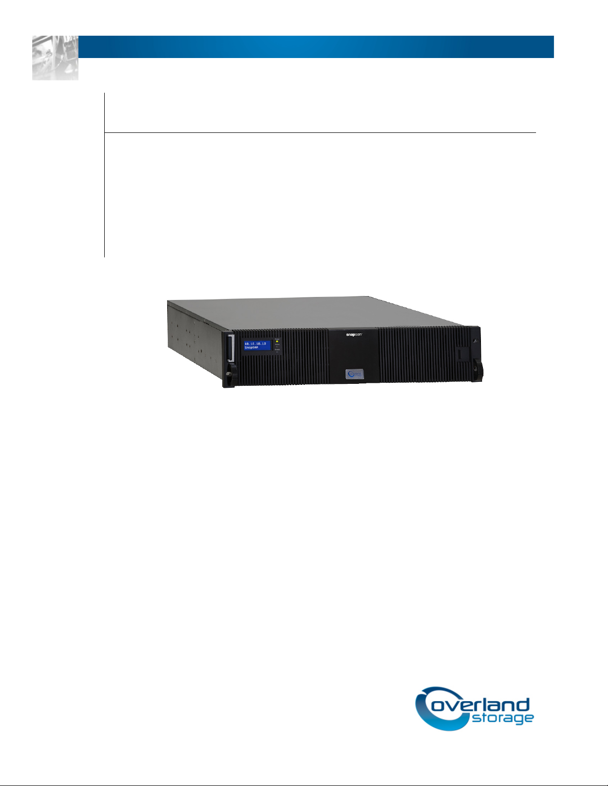
SnapSAN™ S1000
User Guide
January 2013
10400310-003
Page 2

SnapSAN User Guide
©2010-13 Overland Storage, Inc. All rights reserved.
Overland®, Overland Data®, Overland Storage®, ARCvault®, DynamicRAID®, LibraryPro®, LoaderXpress®, Multi-SitePAC®,
NEO
SnapServer
GuardianOS™, RAINcloud™, RapidRebuild™, SnapDisk™, SnapEDR™, Snap Enterprise Data Replicator™, SnapExpansion™,
SnapSAN™, SnapScale™, SnapServer DX Series™, SnapServer Manager™, SnapWrite™, and SnapServer Manager™ are
trademarks of Overland Storage, Inc.
All other brand names or trademarks are the property of their respective owners.
The names of companies and individuals used in examples are fictitious and intended to illustrate the use of the software. Any
resemblance to actual companies or individuals, whether past or present, is coincidental.
PROPRIETARY NOTICE
All information contained in or disclosed by this document is considered proprietary by Overland Storage. By accepting this material
the recipient agrees that this material and the information contained therein are held in confidence and in trust and will not be
used, reproduced in whole or in part, nor its contents revealed to others, except to meet the purpose for which it was delivered. It is
understood that no right is conveyed to reproduce or have reproduced any item herein disclosed without express permission from
Overland Storage.
Overland Storage provides this manual as is, without warranty of any kind, either expressed or implied, including, but not limited
to, the implied warranties of merchantability and fitness for a particular purpose. Overland Storage may make improvements or
changes in the product(s) or programs described in this manual at any time. These changes will be incorporated in new editions of
this publication.
Overland Storage assumes no responsibility for the accuracy, completeness, sufficiency, or usefulness of this manual, nor for any
problem that might arise from the use of the information in this manual.
FM 2.1.1
®
, NEO Series®, PowerLoader®, Protection OS®, REO®, REO 4000®, REO Series®, Snap Appliance®, Snap Care® (EU only),
®
, StorAssure®, Ultamus®, VR2®, and XchangeNOW® are registered trademarks of Overland Storage, Inc.
Overland Storage, Inc.
9112 Spectrum Center Blvd.
San Diego, CA 92123
U.S.A.
Tel: 1.877.654.3429 (toll-free U.S.)
Tel: +1.858.571.5555, Option 5 (International)
Fax: +1.858.571.0982 (general)
Fax: +1.858.571.3664 (sales)
www.overlandstorage.com
10400310-003 01/2013 ©2010-13 Overland Storage, Inc. ii
Page 3

This user guide explains how to install, setup, and use your new Overland Storage SnapSAN
S1000 server.
This guide assumes that you are familiar with computer hardware, data storage, and
network administration terminology and tasks. It also assumes you have basic knowledge of
Fibre Channel, Internet SCSI (iSCSI), Serial-attached SCSI (SAS), Serial ATA (SATA),
Storage Area Network (SAN), and Redundant Array of Independent Disks (RAID)
technology.
Product Documentation and Firmware Updates
Overland Storage SnapSAN product documentation and additional literature are available
online, along with the latest release of the SnapSAN S1000 software.
Point your browser to:
http://support.overlandstorage.com/support/snapsan.htm
Preface
Follow the appropriate link on that page to download the latest software file or document.
For additional assistance, search at http://support.overlandstorage.com.
Overland Technical Support
For help configuring and using your SnapSAN S1000, email our technical support staff at
techsupport@overlandstorage.com.
You can get additional technical support information on the Contact Us web page:
http://docs.overlandstorage.com/support
For a complete list of support times depending on the type of coverage, visit our website at:
http://docs.overlandstorage.com/care
10400310-003 01/2013 ©2010-13 Overland Storage, Inc. iii
Page 4
SnapScale/RAINcloudOS 3.0 User Guide Preface
Conventions
This document exercises several alerts and typographical conventions.
Alerts
Convention Description & Usage
IMPORTANT An Important note is a type of note that provides information essential to
the completion of a task or that can impact the product and its function.
CAUTION A Caution contains information that the user needs to know to avoid
damaging or permanently deleting data or causing physical damage to
the hardware or system.
WARNING
ADVERTISSEMENT
Typographical Conventions
A Warning contains information concerning personal safety. Failure to
follow directions in the warning could result in bodily harm or death.
Un Canadien avertissement comme celui-ci contient des informations
relatives à la sécurité personnelle. Ignorer les instructions dans
l'avertissement peut entraîner des lésions corporelles ou la mort.
Convention Description & Usage
Button_name
Ctrl-Alt-r This type of format details the keys you press simultaneously. In this
NOTE A Note indicates neutral or positive information that emphasizes or
Menu Flow
Indicator (>)
Courier Italic A variable for which you must substitute a value
Courier Bold
Information contained in this guide has been reviewed for accuracy, but not for product
warranty because of the various environments, operating systems, or settings involved.
Information and specifications may change without notice.
Words in this special boldface font indicate the names of command
buttons found in the Web Management Interface.
example, hold down the Ctrl and Alt keys and press the r key.
supplements important points of the main text. A note supplies
information that may apply only in special cases, for example, memory
limitations or details that apply to specific program versions.
Words with a greater than sign between them indicate the flow of actions
to accomplish a task. For example, Setup > Passwords > User indicates
that you should press the
and finally the
Commands you enter in a command-line interface (CLI)
User
Setup
button, then the
button to accomplish a task.
Passwords
button,
10400310-003 01/2013 ©2010-13 Overland Storage, Inc. iv
Page 5

Preface
Chapter 1 - Overview
SnapSAN S1000 Overview ...................................................................................................................................1-1
Hardware ...............................................................................................................................................................1-1
Front Panel ....................................................................................................................................................... 1-1
Disk Drive Assemblies ......................................................................................................................................1-2
Rear Panel .......................................................................................................................................................1-3
RAID Concepts .....................................................................................................................................................1-6
RAID Levels ......................................................................................................................................................1-6
Volume Relationships .....................................................................................................................................1-7
Fibre Channel Concepts .....................................................................................................................................1-7
iSCSI Concepts ......................................................................................................................................................1-8
SAS Concepts .......................................................................................................................................................1-8
Chapter 2 - Installation
First Things First—Activate Your Warranty! ..........................................................................................................2-1
Connection Planning ...........................................................................................................................................2-2
Installation Overview ............................................................................................................................................2-2
Drive Slot Numbering ......................................................................................................................................2-3
Installing the SnapSAN S1000 .........................................................................................................................2-3
Powering ON / OFF ...............................................................................................................................................2-4
Power Up the SnapSAN S1000 .......................................................................................................................2-4
Powering Down the SnapSAN S1000 ............................................................................................................2-4
Contents
Chapter 3 - Basic Configuration
Management Interfaces .....................................................................................................................................3-1
Web Management Interface ........................................................................................................................3-1
Front Panel Display .........................................................................................................................................3-3
Front Panel Display Usage .............................................................................................................................3-6
Serial Console ..................................................................................................................................................3-6
Secure Shell Remote Access .........................................................................................................................3-6
Chapter 4 - Web Management Interface
Interface Hierarchy ..............................................................................................................................................4-1
System Configuration ...........................................................................................................................................4-3
System Settings ................................................................................................................................................4-3
Network Settings .............................................................................................................................................4-4
Login Settings ..................................................................................................................................................4-4
Email Notification Settings .............................................................................................................................4-5
Log and Alert Settings ....................................................................................................................................4-5
10400310-003 01/2013 ©2010-13 Overland Storage, Inc. v
Page 6

SnapSAN S1000 User Guide Contents
Fibre Channel Configuration ...............................................................................................................................4-7
iSCSI Configuration ...............................................................................................................................................4-7
Network Setup .................................................................................................................................................4-7
Entity and iSNS Settings ................................................................................................................................4-10
iSCSI Nodes ....................................................................................................................................................4-11
Active Sessions ..............................................................................................................................................4-13
CHAP Accounts ............................................................................................................................................4-15
Volume Configuration .......................................................................................................................................4-17
Physical Disks .................................................................................................................................................4-17
RAID Groups ..................................................................................................................................................4-18
Virtual Disks ....................................................................................................................................................4-22
Snapshots .......................................................................................................................................................4-25
Logical Units ...................................................................................................................................................4-27
Volume Creation Example ..........................................................................................................................4-28
Enclosure Management ....................................................................................................................................4-32
Hardware Monitor .........................................................................................................................................4-33
UPS ..................................................................................................................................................................4-34
SES ...................................................................................................................................................................4-35
S.M.A.R.T. ........................................................................................................................................................4-35
System Maintenance .........................................................................................................................................4-36
System Information ....................................................................................................................................... 4-37
Event Log .......................................................................................................................................................4-37
Upgrade .........................................................................................................................................................4-38
Firmware Synchronization ............................................................................................................................4-38
Reset to Factory Defaults .............................................................................................................................4-39
Configuration Backup ..................................................................................................................................4-39
Reboot and Shutdown .................................................................................................................................4-40
How To Use the Guided Configurations ...........................................................................................................4-40
Quick Installation Tool ..................................................................................................................................4-40
Volume Creation Wizard ..............................................................................................................................4-42
Home/Logout/Mute Icons .................................................................................................................................4-44
Home ..............................................................................................................................................................4-44
Logout ............................................................................................................................................................4-44
Mute ...............................................................................................................................................................4-44
Chapter 5 - Advanced Operations
Volume Auto-Rebuild ...........................................................................................................................................5-1
RAID Group Migration ..........................................................................................................................................5-2
Virtual Disk Extension ............................................................................................................................................5-4
Snapshots ..............................................................................................................................................................5-4
Create the Snapshot Space ..........................................................................................................................5-5
Take a Snapshot .............................................................................................................................................5-5
Clean (Delete) Snapshots ..............................................................................................................................5-6
Schedule Automatic Snapshots ....................................................................................................................5-6
Rollback ...........................................................................................................................................................5-7
Snapshot Constraints ......................................................................................................................................5-7
VSS Software ....................................................................................................................................................5-9
Disk Roaming .........................................................................................................................................................5-9
Expansion Arrays .................................................................................................................................................5-10
Connecting Expansion Arrays .....................................................................................................................5-10
Upgrade Firmware of SnapDisk E1000 ........................................................................................................5-12
10400310-003 01/2013 ©2010-13 Overland Storage, Inc. vi
Page 7

SnapSAN S1000 User Guide Contents
MPIO and MC/S ..................................................................................................................................................5-12
Trunking and LACP .............................................................................................................................................5-14
Dual Controllers ..................................................................................................................................................5-15
Perform I/O ....................................................................................................................................................5-16
Ownership ......................................................................................................................................................5-16
Controller Status ............................................................................................................................................5-17
Redundancy .................................................................................................................................................5-18
Chapter 6 - Troubleshooting
System Buzzer ........................................................................................................................................................6-1
Event Notifications ................................................................................................................................................ 6-1
Chapter 7 - VSS Installation
Theory of Operation .............................................................................................................................................7-1
Software Installation .............................................................................................................................................7-2
Using SnapSAN S1000 VSS ....................................................................................................................................7-3
Creating a Snapshot ......................................................................................................................................7-3
Listing Snapshots .............................................................................................................................................7-3
Exposing a Snapshot ......................................................................................................................................7-3
Chapter 8 - Replication
Introduction ...........................................................................................................................................................8-1
Network configuration .........................................................................................................................................8-1
Network Diagram .................................................................................................................................................8-2
Configure Replication ..........................................................................................................................................8-2
Activate the RAID Subsystem License Key ...................................................................................................8-2
Set Up the Replication Port On The Source .................................................................................................8-3
Create A Backup Virtual Disk On The Target ...............................................................................................8-4
Create Replication Job On The Source .......................................................................................................8-5
Working with Replication Jobs ............................................................................................................................8-7
Run a Replication Job ....................................................................................................................................8-7
Create a Replication Job Multi-Path Setting ...............................................................................................8-8
Schedule a Replication Job ..........................................................................................................................8-9
Configure Snapshot Space ...............................................................................................................................8-10
How Replication Redundancy Works ..............................................................................................................8-11
Normal Operation .........................................................................................................................................8-11
Controller 1 Fails on Source .........................................................................................................................8-12
Controller 1 Fails on Target ..........................................................................................................................8-12
Create Multiple Replication Jobs .....................................................................................................................8-12
First Time Best Practices ...................................................................................................................................... 8-13
Overland Glossary & Acronym List
Index10400310-003
10400310-003 01/2013 ©2010-13 Overland Storage, Inc. vii
Page 8
Chapter 1
SnapSAN S1000 Overview
This user guide describes how to set up and use the Overland Storage SnapSAN S1000.
The storage array, available in different configurations of iSCSI, Fibre Channel, and SAS
interfaces, together with the SnapSAN S1000 installed software, provides a flexible,
intelligent, storage area network (SAN) solution for virtualized server environments and the
growing demand for data storage. With a SnapSAN S1000, you can store, share, protect, and
manage data through a single easy-to-use web interface.
Overview
Hardware
This section provides basic information about the hardware components.
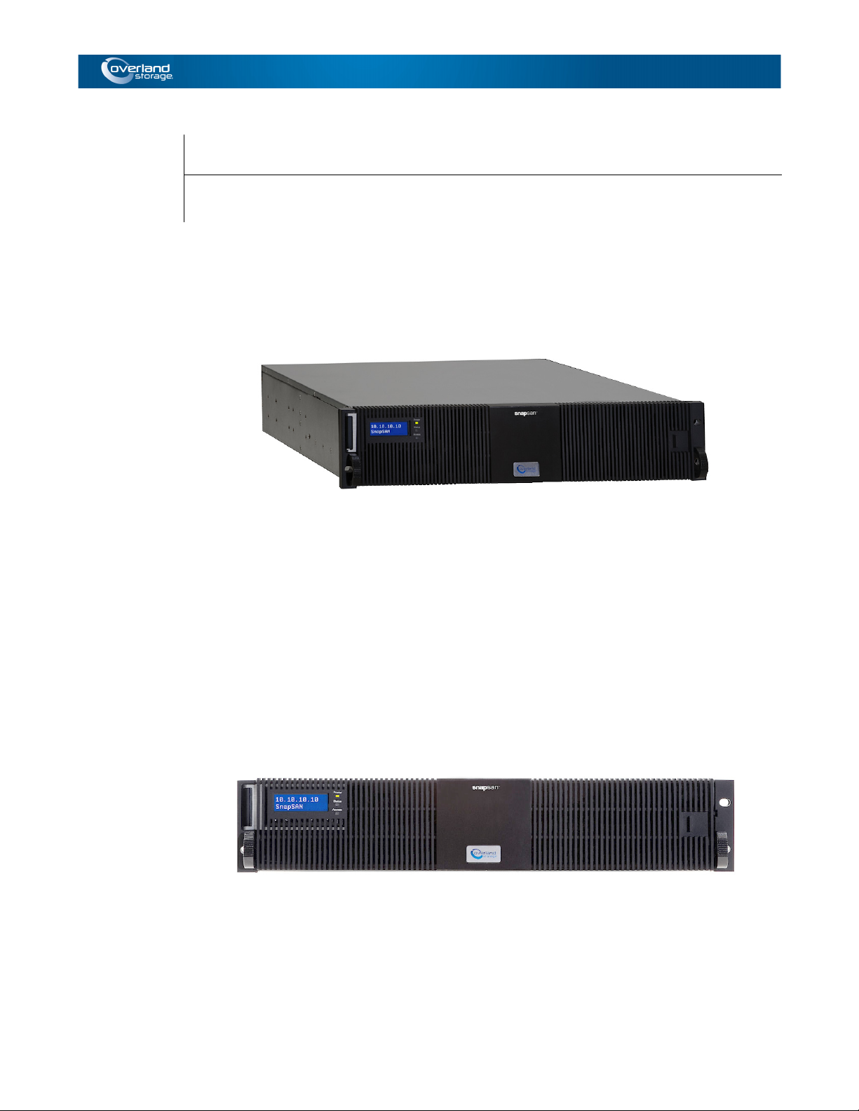
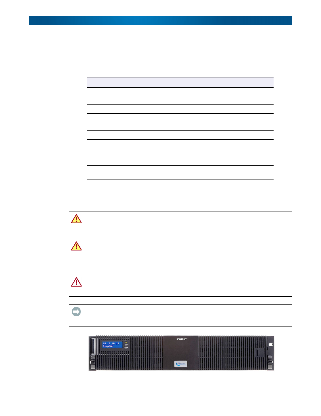
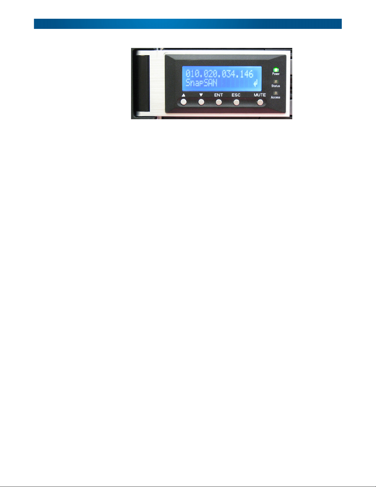
Front Panel
The front of a SnapSAN S1000 server with the bezel attached:
The Front Panel Display control panel is located in the upper left corner.
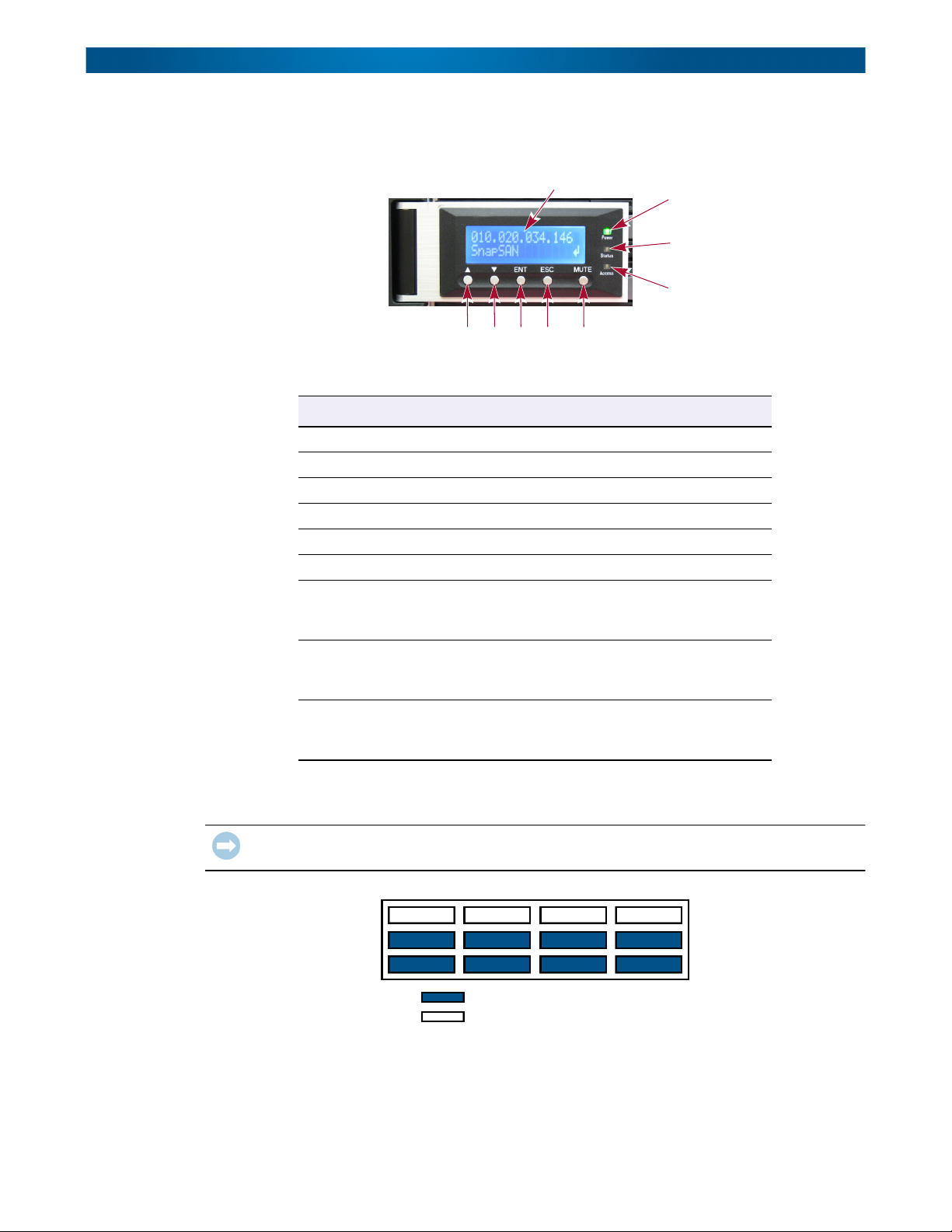
Front Panel Display
There are five buttons to control SnapSAN S1000 Front Panel Display, including: ▲ (up), ▼
(down), ENT (Enter), ESC (Escape) and MUTE.
10400310-003 01/2013 ©2010-13 Overland Storage, Inc. 1-1
Page 9
SnapSAN S1000 User Guide Hardware
NOTE: The buttons are covered when the bezel is installed. However, the Front Panel Display and
three LEDs are still visible with the bezel attached.
1
7
8
9
65324
This table shows the items located on the Front Panel Display:
Number Description
1 LCD display (0.75” x 2.0”), white text on a blue background
2 Up button (▲)
3 Down button (▼)
4 ENT (Enter) button
5 ESC (Escape) button
6 Mute button
7 Power LED:
Green = Power ON
Off = Power OFF
8 Status LED:
Red = System failure
Off = No problems
9 Access LED:
Green = Host is accessing storage array
Off = No Host access attempts
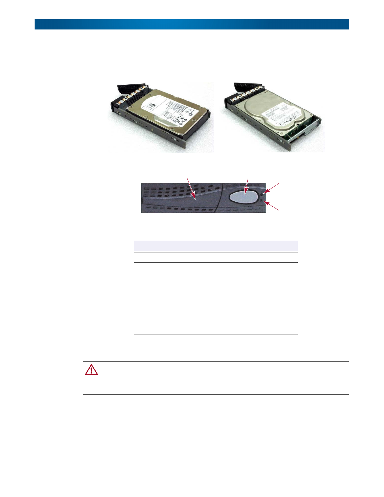
Disk Drive Assemblies
IMPORTANT: For proper cooling, every slot must have either a disk drive assembly or a blank
disk assembly in it.
Blank Disk Assembly
Empty Slot
10400310-003 01/2013 ©2010-13 Overland Storage, Inc. 1-2
Page 10
SnapSAN S1000 User Guide Hardware
Disk drive assemblies consist of a SnapSAN S1000 disk tray with either SAS, SATA II, or
Green SATA II disk drive preinstalled in it. A blank assembly consists of a special empty
tray used to ensure proper airflow within the enclosure. Eight blank assemblies are included
with the server.
SAS SATA II and
Green SATA II‘
The front of each disk tray has four components:
This table provides details about the front components of a disk tray:
Rear Panel
1
Number Description
1 Tray removal handle.
2 Latch to release the tray and tray handle.
3 Power LED:
Green = Drive is inserted and good.
Red = Drive has failed.
OFF = No disk drive in the tray.
4 Access LED:
Blue blinking = The disk drive is being accessed.
OFF = The disk drive is not being accessed or
there is no disk drive in the tray.
2
3
4
CAUTION: To prevent data loss, when powering down the SnapSAN S1000, perform a normal
shutdown (see “Powering Down the SnapSAN S1000” on page 2-4) to flush any data from the
cache to the physical disks, as opposed to simply turning the power OFF. All active initiators need to
be logged off before shutting the server down.
10400310-003 01/2013 ©2010-13 Overland Storage, Inc. 1-3
Page 11
SnapSAN S1000 User Guide Hardware
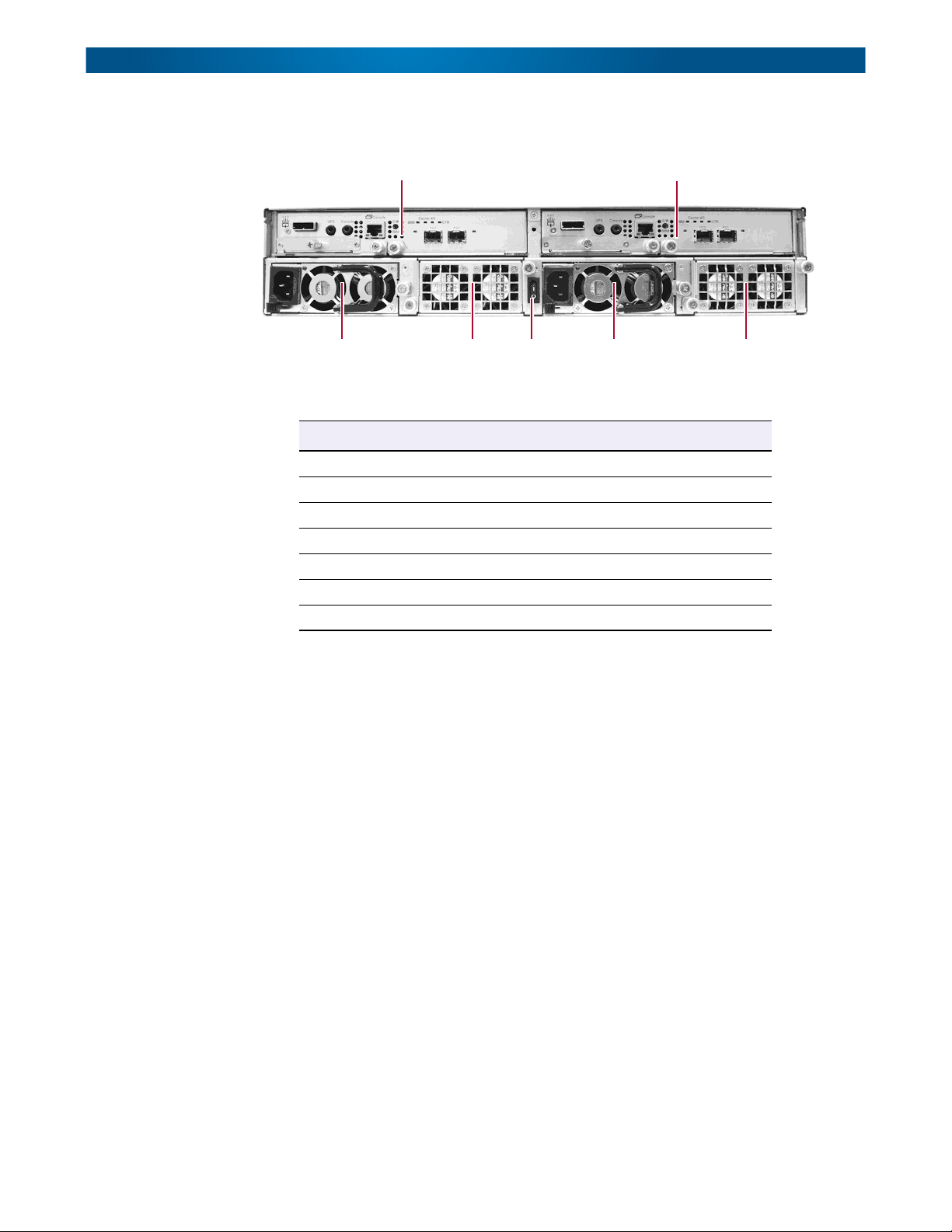
The individual components are all configured as removable modules and are accessible from
the rear.
1
3
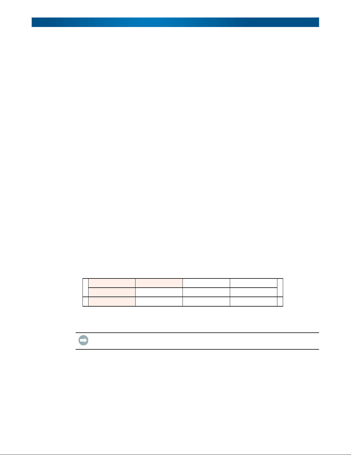
This table describes the rear components:
Callout Description Rear Label
1 Controller 2 (Optional) CL2
2 Controller 1 CL1
3 Power Supply Unit 1 PSU1
4 Fan Module FAN1/2
5 Power Switch (“|”=ON and “O”=OFF) (none)
6 Power Supply Unit 2 PSU2
7 Fan Module FAN3/4
4
2
56 7
Controllers
All controllers for the SnapSAN S1000 are shipped in separate packaging. Each comes with
its own Battery Backup Module (BBM).
NOTE: To facilitate support of your controllers, each BBM must be installed in the controller with
which it came packaged. All controllers and batteries must be registered with the SnapSAN
S1000 in which they are installed.
By default, the SnapSAN S1000 is configured as a single controller system. To change it to a
dual controller system with Master and Secondary controllers:
1. Install the optional Secondary controller.
2. Go to System Maintenance > Upgrade > Controller Mode.
3. Using the drop-down list, select Dual and click Apply.
For the dual controller setup, both controllers must be the same type (for example,
10Gb iSCSI controllers).
10400310-003 01/2013 ©2010-13 Overland Storage, Inc. 1-4
Page 12
SnapSAN S1000 User Guide Hardware
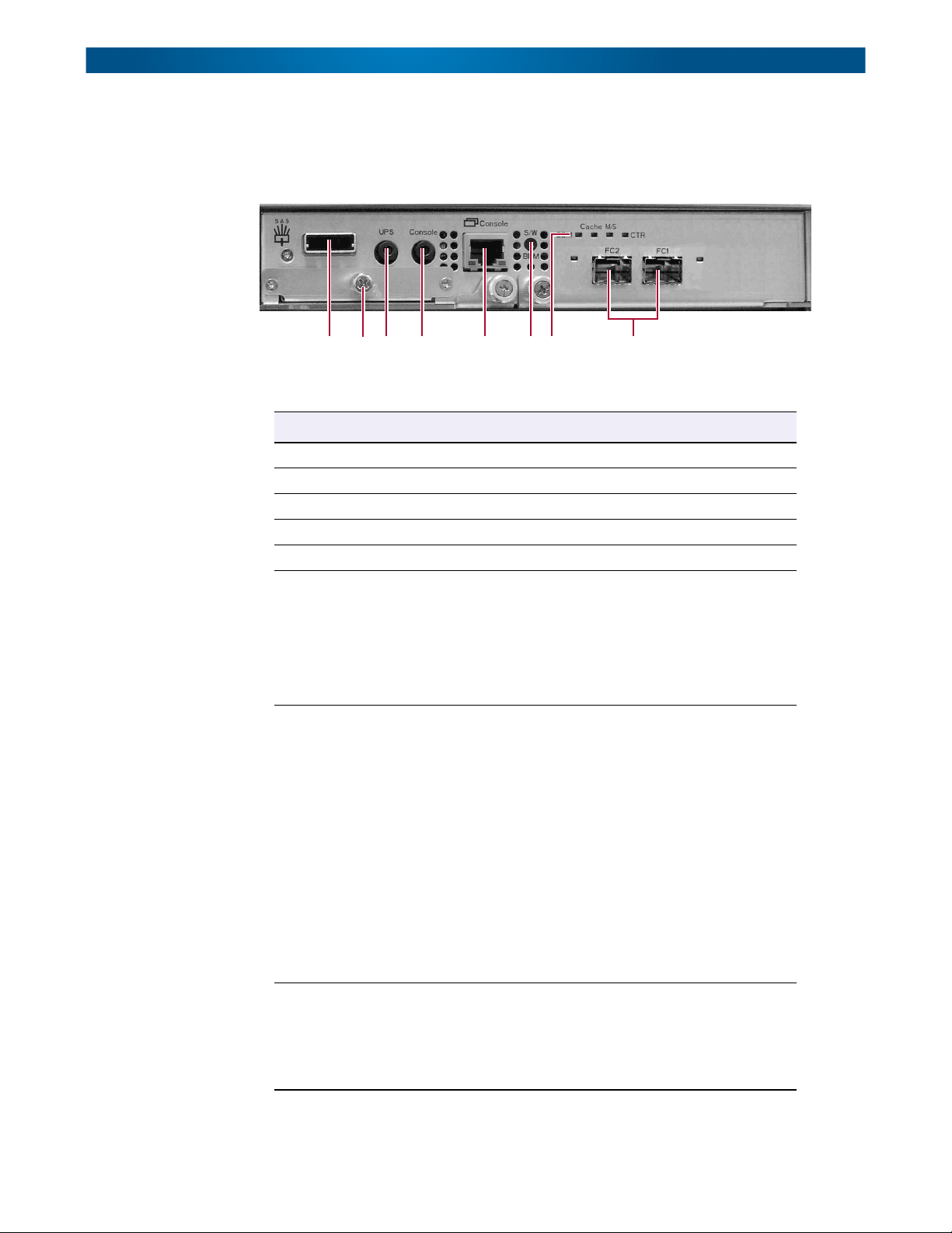
There are four different controllers available for the SnapSAN S1000. With the exception of
the host SAN ports, the connections are the same on all four modules:
Dual-PORT 4Gb Fibre Channel controller:
1 34 5 6 82 7
This table details the items called out in the controller components photos:
Number Description
1 Expansion array port (SAS)
2 Battery Backup Module (BBM) slot
3 Port for APC Smart-UPS communication
4 Console serial port
5 Management console port
6 BBM status button – used to check the battery when the power is OFF.
Press the Status button to activate:
• If the LED shows Green, then the BBM still has power to keep data
in the cache.
• If LED stays OFF, then the BBM power has run out and it cannot
provide power for the cache anymore. It needs to be recharged or
replaced.
7 LEDs (from left to right):
• BBM LED (when status button pressed):
Green = BBM installed and powered.
Off = No BBM installed or dead.
• Cache LED:
Orange = Data on the cache waiting for flush.
Off = No data on the cache.
• Master Slave (MS) LED:
Green = This is the Master controller.
Off = This is the Slave controller.
• Controller (CTR) Health LED:
Green = Controller status normal.
Red = System booting or controller is not working
properly. For example, a hardware failure or
software error causing a hang.
8 SAN ports (depending on model):
• 4Gb Fibre Channel ports (x2) (shown without SFP modules)
• Gigabit iSCSI ports (x4)
• 10Gb iSCSI ports (x2) (shown without SFP+ modules)
• 6Gb SAS ports
10400310-003 01/2013 ©2010-13 Overland Storage, Inc. 1-5
Page 13
SnapSAN S1000 User Guide RAID Concepts
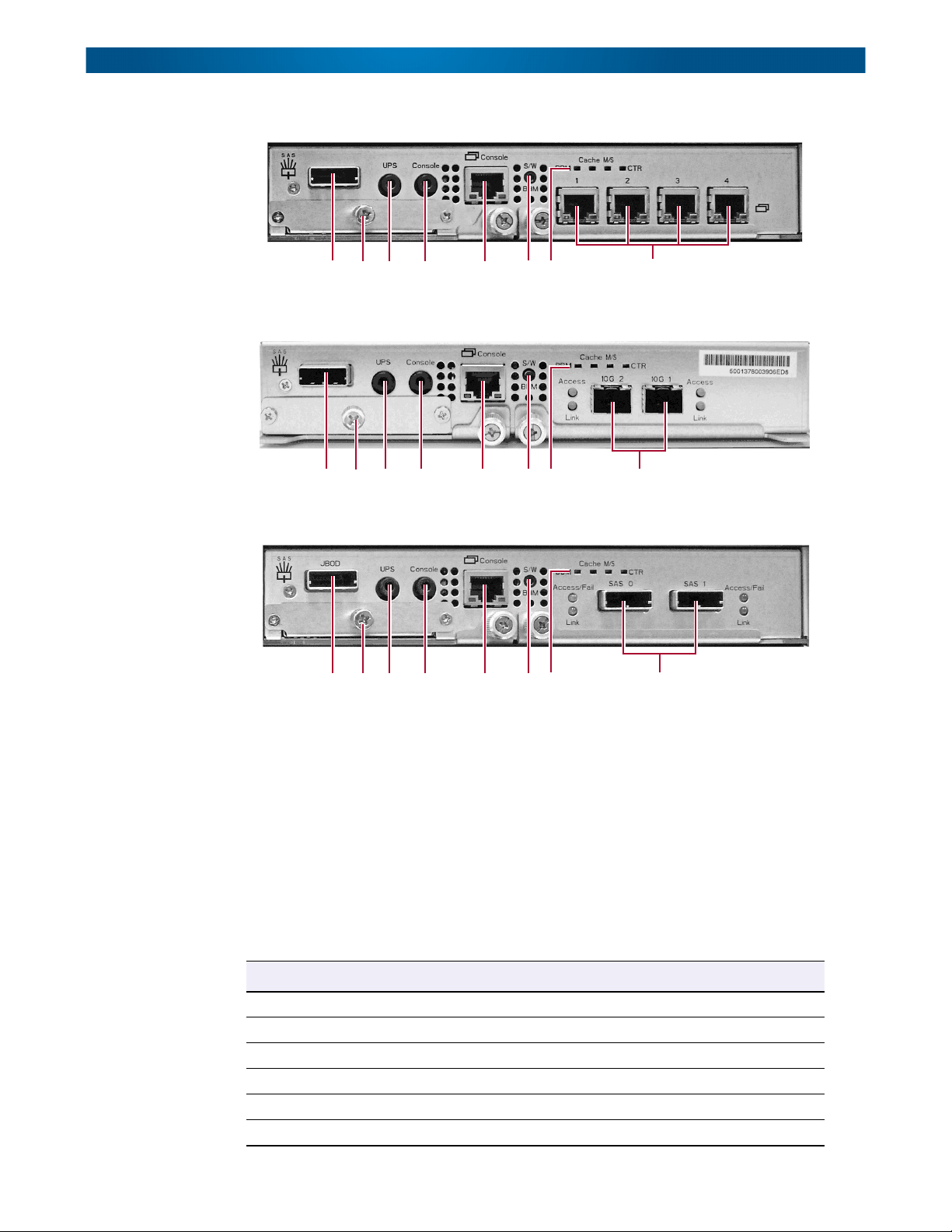
Four-Port Gigabit (Gb) iSCSI controller:
1 34 5 6 82 7
Dual-Port 10Gb iSCSI controller:
RAID Concepts
RAID Levels
1 34 5 62 7
Dual-Port 6Gb SAS controller:
1 34 5 62 7
RAID is the abbreviation of Redundant Array of Independent Disks. The basic idea of RAID
is to combine multiple individual drives together to form one large logical drive or volume.
The operating system detects the RAID drive as a single storage device.
There are different RAID levels with different degrees of data protection, data availability,
and performance. A description of supported RAID levels follow:
8
8
Type Description Min. No. of Drives
RAID 0 Disk striping. At least one
RAID 1 Disk mirroring over two disks. At least two
RAID 3 Disk striping with parity on a dedicated disk. At least three
RAID 5 Disk striping with distributed parity. At least three
RAID 6 Disk striping with dual-distributed parity. At least four
RAID 0+1 Disk mirroring of a RAID 0 group. At least four
10400310-003 01/2013 ©2010-13 Overland Storage, Inc. 1-6
Page 14
SnapSAN S1000 User Guide Fibre Channel Concepts
Type Description Min. No. of Drives
RAID 10 Disk striping of a RAID 1 group. At least four
RAID 30 Disk striping of a RAID 3 group. At least six
RAID 50 Disk striping of a RAID 5 group. At least six
RAID 60 Disk striping of a RAID 6 group. At least eight
JBOD Independently address a drive. At least one
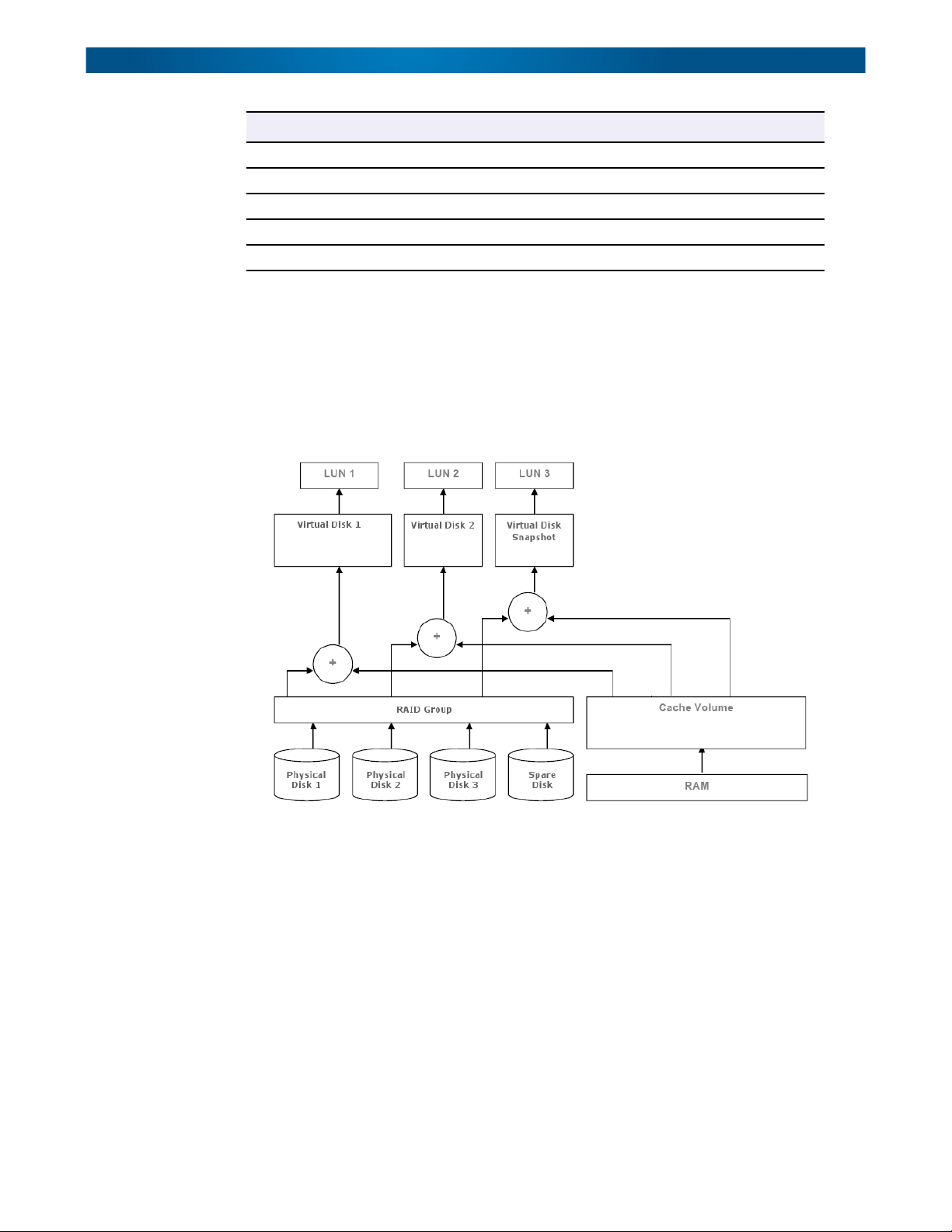
Volume Relationships
The following graphic describes the relationship of RAID components. One RAID Group
consists of a set of virtual disks and owns one RAID level attribute. Each RAID Group can be
divided into several virtual disks. The virtual disks in one group share the same RAID level,
but may have different volume capacities. All virtual disks share the Cache Volume (CV) to
execute the data transaction. Logical Unit Number (LUN) is a unique identifier, in which
users can access through SCSI commands.
Fibre Channel Concepts
Fibre Channel is a gigabit-speed network technology which transports SCSI commands over
Fibre Channel networks. Fibre Channel was primarily concerned with simplifying the
connections and increasing distances, but later designers added the goals of connecting SCSI
disk storage, providing higher speeds and far greater numbers of connected devices.
The SnapSAN S1000 Fibre Channel controller only supports loop networks. It does not work
with Fabric networks.
A Fibre Channel Arbitrated Loop (FC-AL) is a Fibre Channel network in which up to 126
systems and devices are connected in a loop topology, with each transmitter connecting to
the receiver of the device on its logical right. The Fibre Channel Arbitrated Loop protocol
used for transmission is different from Fibre Channel switched and point-to-point protocols.
Multiple FC-AL loops can be connected via a fabric switch to extend the network.
10400310-003 01/2013 ©2010-13 Overland Storage, Inc. 1-7
Page 15
SnapSAN S1000 User Guide iSCSI Concepts
iSCSI Concepts
Internet SCSI (iSCSI) is a protocol which encapsulates SCSI commands and data in TCP/IP
packets for linking storage devices with servers over common IP infrastructures. iSCSI
provides high performance Storage Area Networks (SAN) over standard IP networks like
LAN, WAN, or the Internet.
IP SANs are true Storage Area Networks which allow several servers to attach to an infinite
number of storage volumes by using iSCSI over TCP/IP networks. IP SANs can scale the
storage capacity with any type and brand of storage system. In addition, it can be used by
any type of network (Ethernet, Fast Ethernet, Gigabit Ethernet, and 10-Gigabit Ethernet)
and any combination of operating systems (Microsoft Windows, Linux, Solaris, Mac OS X,
etc.) within the SAN network. IP SANs also include mechanisms for security, data
replication, multi-path, and high availability.
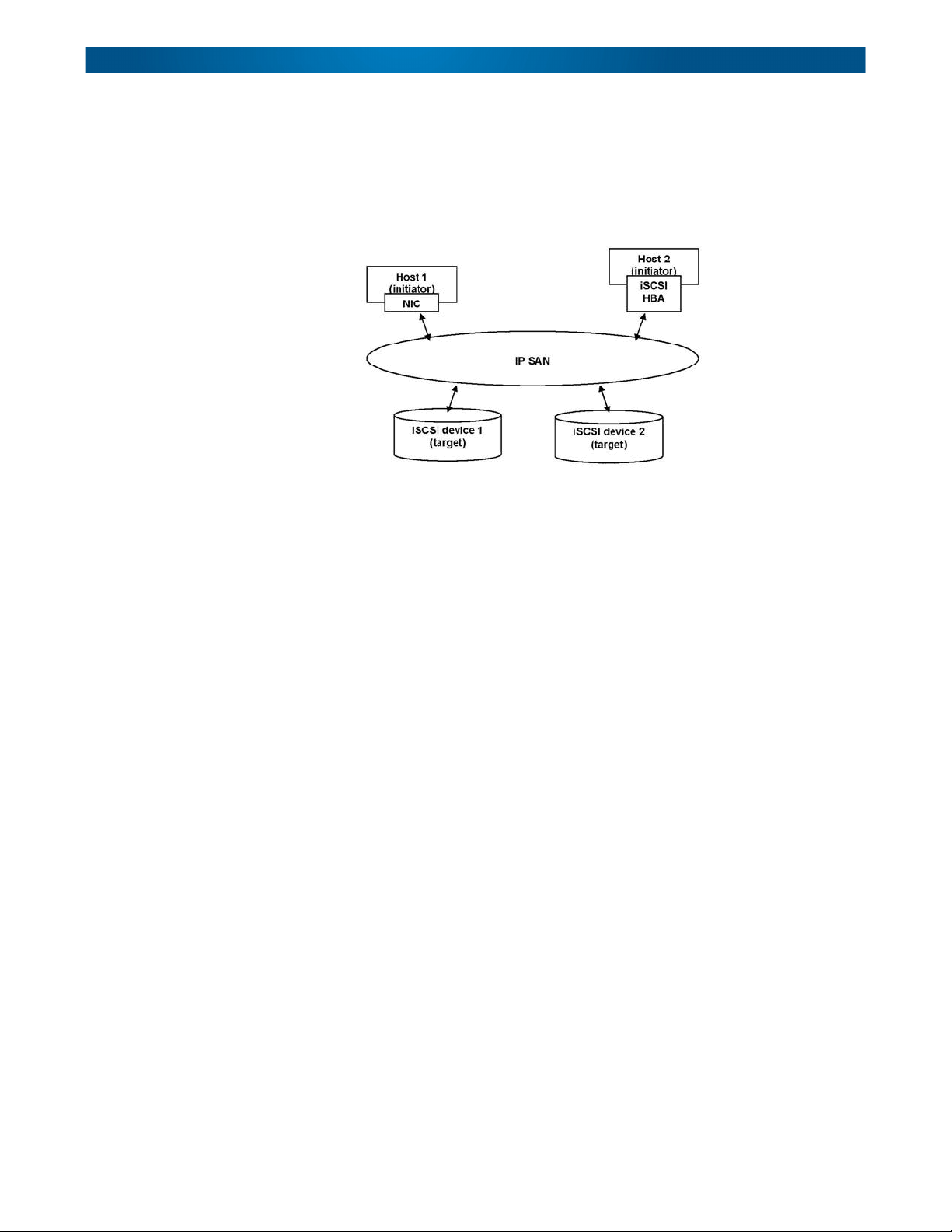
Storage protocols, such as iSCSI, have “two ends” in the connection. These ends are initiator
and target. In iSCSI, they are called the iSCSI initiator and the iSCSI target. The iSCSI
initiator requests or initiates any iSCSI communication like read or write. The iSCSI target
can be the storage device itself or an appliance which controls and serves volumes or virtual
volumes. It performs SCSI commands sent by the initiator or is a bridge to an attached
storage device.
The initiator can be either software or hardware (HBA). Refer to the SnapSAN S1000
Compatibility Guide on the Overland Storage web site for the latest certification list. OS
native initiators or other software initiators use standard TCP/IP stack and Ethernet
hardware, while iSCSI HBAs use their own iSCSI and TCP/IP stacks on board. Hardware
iSCSI HBAs also provide their own initiator tool. Please refer to the vendors’ HBA user
guide. Microsoft, Linux, Solaris, and Mac provide software versions of iSCSI initiator
drivers.
SAS Concepts
SAS, short for Serial Attached SCSI, is a point-to-point serial protocol that replaces parallel
SCSI bus technology (multidrop) and uses the standard SCSI command set. It has no
termination issues, supports up to 16,384 devices (using expanders), and eliminates clock
skew. It consists of an Initiator that originates device service requests, a Target containing
logical units that receives device service requests, and a Service Delivery Subsystem that
transmits information between the Initiator and the Target.
With the availability of 3Gbps and 6Gbps SAS, performance is now on par with fibre channel
design and in highly random read environments can outperform fibre channel.
10400310-003 01/2013 ©2010-13 Overland Storage, Inc. 1-8
Page 16

SnapSAN S1000 User Guide SAS Concepts
The number of host computer connections depend on how the SnapSAN S1000 is connected:
• A single SAS controller system supports two (2) direct host connections.
• A dual SAS controller system supports four (4) direct host connections.
• With a switch placed between the SnapSAN S1000 and the host computers, either SAS
controller system can support up to 32 host connections.
10400310-003 01/2013 ©2010-13 Overland Storage, Inc. 1-9
Page 17
Chapter 2
This chapter explains how to install your SnapSAN S1000. Sections in this chapter include:
• First Things First—Activate Your Warranty!
• Connection Planning
• Installation Overview
• Powering ON / OFF
First Things First—Activate Your Warranty!
Before installing your new SnapSAN S1000, drives, and controllers, it is essential that you
activate your Overland warranty. Technical and warranty support are not available until
this is done:
NOTE: The serial number of the chassis, controllers, and battery backup modules from the
attached labels are needed to complete this process.
Installation
1. Go to the Overland Storage web site at:
http://www.overlandstorage.com/
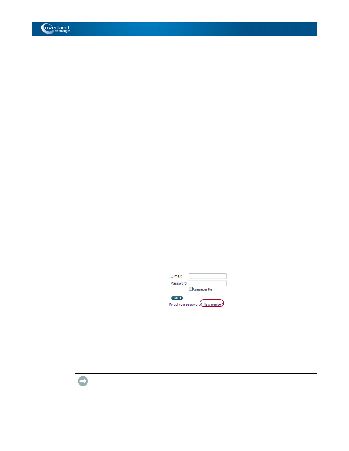
2. Select Service & Support > My Products.
3. At the Site Login, enter your email address and password.
NOTE: If you are not yet a member, click “New member?” and follow the instructions given. It’s
free and easy!
4. Under the My Products tab, click Register New.
5. Fill in the Server information and click Submit.
6. Repeat Steps 4–5 for all the drive packs, controllers, and BBMs.
Serial numbers can be found on the box labels.
IMPORTANT: Within three business days after registering, you will receive an email from
Overland with your warranty certificate. Review it carefully and verify that the product and
address information is accurate. If errors are found, email us at: warranty@overlandstorage.com.
The System Maintenance > System Information tab also provides useful information for
registering the product.
10400310-003 01/2013 ©2010-13 Overland Storage, Inc. 2-1
Page 18
SnapSAN S1000 User Guide Connection Planning
Connection Planning
Use this checklist to help you plan the incorporation of your single controller SnapSAN
S1000 into your SAN network. For a dual-controller system (shown in square brackets),
double the number of connections:
Type Connection
IP Address DHCP (default) or Static
GbE Switch One [or two] RJ45
Host:
Fibre Channel Two [or four] 4Gbs (SFP) on a Fibre switch
1Gb iSCSI Four [or eight] 1Gbs (RJ45) on a 1Gb Ethernet switch
10Gb iSCSI Two [or four] 10Gbs (SFP+) on a 10Gb Ethernet switch
SAS Direct One [or two] 6Gbs (or 3Gbs) SAS (SFF-8088) available on
each host. Two [or four] for connections with redundancy.
Maximum of four [or eight] hosts with dual controllers
without redundancy or two [or four] with redundancy.
SAS Switched Two [or four] 6Gbs (or 3Gbs) SAS (SFF-8088) available on
SAS switch to desired hosts
Installation Overview
WARNING: It is recommended that a mechanical lifter (or at least two people) be used to raise
and align the unit to prevent injury during installation. Use care when inserting or removing a
unit into or out of a rack to prevent the accidental tipping of the rack causing damage or personal
injury.
AVERTISSEMENT: il est recommandé que la mécanique lifter (ou au moins deux personnes)
soit utilisé pour élever et d'unifier l'appareil pour éviter des blessures pendant l'installation.
Faites attention lorsque vous insérer ou de retirer une unité d'entrée ou de sortie d'un support pour
empêcher le déversement accidentel de la crémaillère causant des dommages ou des blessures.
CAUTION: Overland strongly recommends that you install the unit in a clean, air-conditioned
environment with power conditioning and an adequately rated uninterruptible power supply
(UPS). The unit is intended to be grounded.
IMPORTANT: Before unpacking the unit, ensure that the area is free from conditions that
cause electrostatic discharge (ESD). Discharge static electricity from your body by touching a
known grounded surface. Also, avoid touching pins, leads, or circuitry.
10400310-003 01/2013 ©2010-13 Overland Storage, Inc. 2-2
Page 19
SnapSAN S1000 User Guide Installation Overview
Before starting, prepare the following items:
• A host with a Gigabit Ethernet NIC (recommended).
• A management computer on the same network as the SnapSAN S1000.
• Use either CAT 5e or CAT 6 (recommended) network cables for the management port
and the iSCSI data ports (10GB and 1Gb controllers only).
• A storage system configuration plan by your network administrator.
The plan should include network information for the management port and iSCSI data
ports. If using static IP addresses, prepare a list of the static IP addresses, the subnet
mask, and the default gateway.
• Gigabit switches (recommended) or Gigabit switches with VLAN / LACP / Trunking
(optional):
• For a 4-port Gigabit S1000, 4 or 8 available ports on a Gigabit switch.
• For a 2-port 10GbE S1000, 2 or 4 available 10Gb ports with SFP+ connections.
• For a 2-port Fibre Channel S1000, 2 or 4 available 4Gb Fibre Channel ports with
SFP connectors.
• For a 2-port SAS S1000, 2 or 4 available 6Gb SAS ports with SFP connectors (or
connect directly to hosts with SFP connectors for Direct Attach Storage (DAS)
configuration).
• CHAP security information, including CHAP user name and secret (optional). See
“Overland Glossary & Acronym List” for details.
• For dual-controller systems, it is recommended that the host logon to the target twice
(both Controller 1 and Controller 2), and then the MPIO should setup automatically.
• For an iSCSI dual-controller system, install an iSNS server on the same LAN
(recommended).
Drive Slot Numbering
The drives can be installed into any slot in the enclosure. Slot numbering is reflected in Web
Management Interface.
1 4 7 10
2 5 8 11
3 6 9 12
Different capacity drives can be installed; however, they should not be in the same RAID set,
because capacity usage for all drives in the RAID is limited to the smallest drive capacity.
IMPORTANT: Install at least one drive in Slots 1 to 4 (shaded slots). System event logs are
saved in these drives. Otherwise, event logs no longer exist after a reboot.
Installing the SnapSAN S1000
Using detailed instructions from the SnapSAN S1000 Quick Start Guide that came in the
Accessory Kit, install the unit in the rack as follows:
1. Install the Battery Backup Modules in their appropriate controllers.
2. At the rear, install the Master controller in its slot (CL1).
3. If desired, install the optional Secondary Controller in its slot (CL2).
10400310-003 01/2013 ©2010-13 Overland Storage, Inc. 2-3
Page 20
SnapSAN S1000 User Guide Powering ON / OFF
4. Install the Rail Kit onto the unit and insert it into the rack.
5. Install the Disk Drive assemblies.
6. Connect the data and management cables based on the network plan.
7. Attach the power cords and power ON the unit.
8. Confirm or set the IP address and start the configuration for your needs.
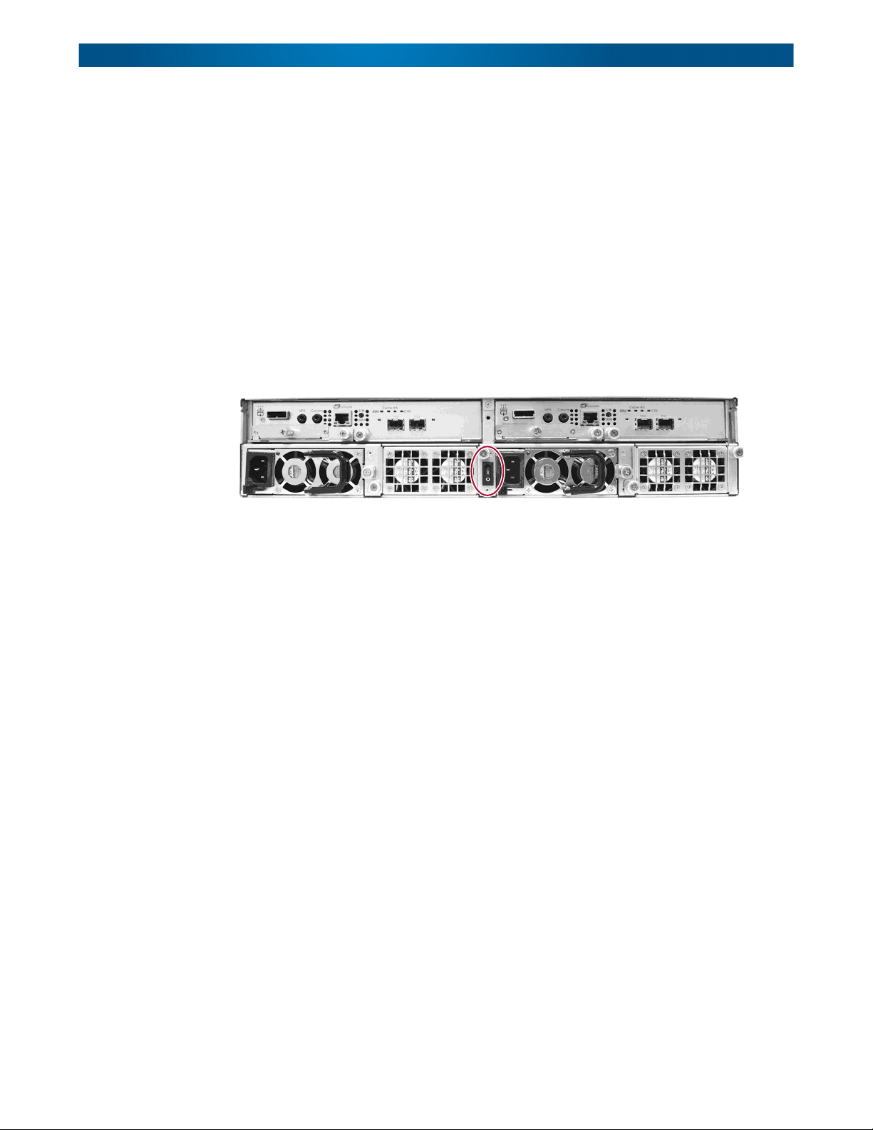
Powering ON / OFF
Power Up the SnapSAN S1000
The power switch is located in the center of the rear panel’s lower section. To turn the
storage array ON, press “|” (switch top).
After you turn the power ON, the System performs a self-test process, which takes a couple
of minutes.
Powering Down the SnapSAN S1000
If it becomes necessary to power down the system, it is recommended using a normal,
controlled shutdown from either the Front Panel Display or the Web Management Interface
to ensure all data is flushed from the cache first.
Shutdown Using the Web Management Interface
Using the Web Management Interface:
1. Select System Maintenance > Reboot and Shutdown.
2. Click the Shutdown icon.
3. When the “System Shutdown” message is shown on the Front Panel Display, move the
main power switch to OFF (O).
Shutdown Using Front Panel Display
At the Front Panel Display:
1. Power off the unit using a normal shutdown.
a. Press ENT.
b. Press ▼ twice to show Reboot/Shutdown, and press ENT.
c. Press ▼ once to show Shutdown, and press ENT.
d. Press ▲ once to highlight Yes, and press ENT.
A controlled shutdown begins.
10400310-003 01/2013 ©2010-13 Overland Storage, Inc. 2-4
Page 21

SnapSAN S1000 User Guide Powering ON / OFF
2. When the “System Shutdown” message is shown, move the main power switch to
OFF (O).
10400310-003 01/2013 ©2010-13 Overland Storage, Inc. 2-5
Page 22
Chapter 3
Management Interfaces
There are two primary methods to manage a SnapSAN S1000—the Web Management
Interface and the Front Panel Display.
Web Management Interface
For remote management and daily usage, the SnapSAN S1000 uses a web graphic user
interface called the Web Management Interface. It supports most common web browsers,
including Internet Explorer 7 or 8, and Firefox 3.5. JavaScript must be enabled in the
browser and a LAN cable connected to the Management port of the SnapSAN S1000.
The default IP setting is DHCP. Check the Front Panel Display to find the DHCP address
displayed there. If your network doesn’t have a DHCP server, you will need to configure a
static IP address using the Front Panel Display (as detailed in the SnapSAN S1000 Quick
Start Guide).
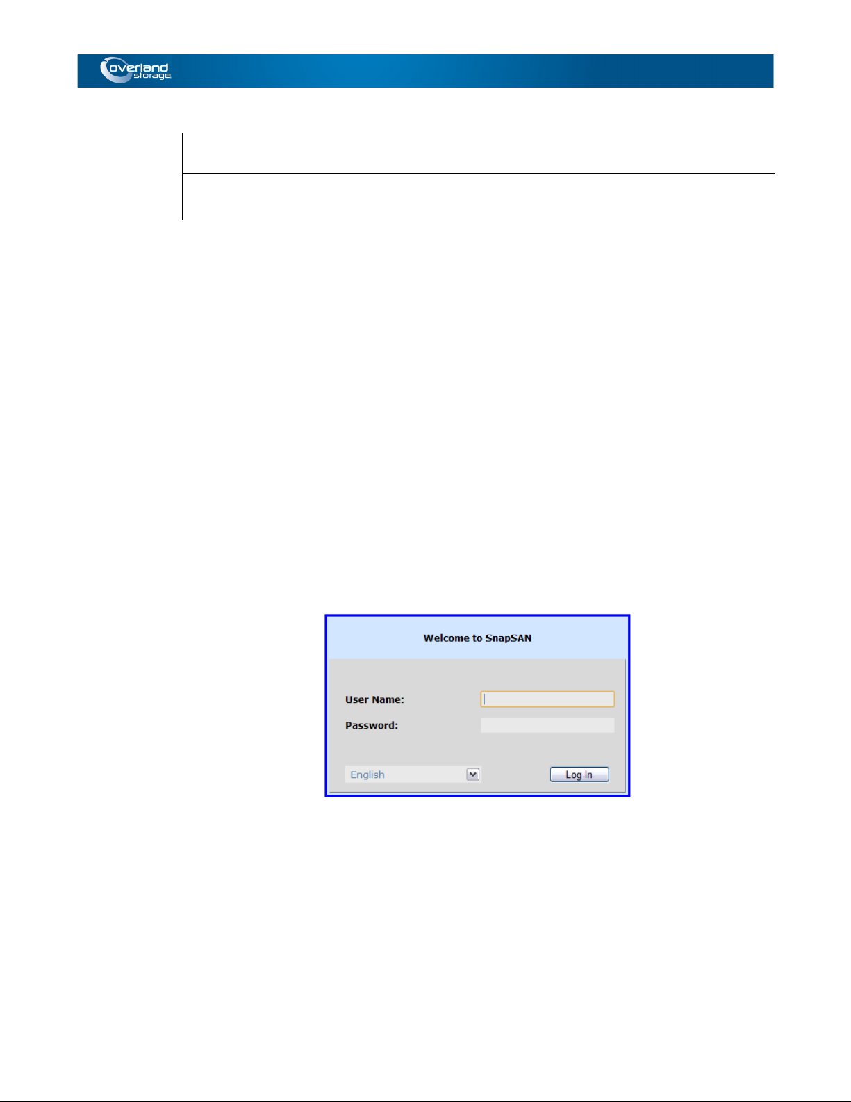
Enter the unit’s IP address into your browser to access the authentication screen. With some
browsers, you may need to prefix the address with “http://” (for example,
“http://192.168.10.50”).
Basic Configuration
To access the Web Management Interface of the SnapSAN S1000, you must enter a user
name and password. The initial defaults for Administrator login are:
User Name: admin
Password: admin
NOTE: For user level access, enter “user” as the User Name and no password. If needed, you can
add a User password by logging on as the Administrator and going to System Configuration
> Login Settings.
10400310-003 01/2013 ©2010-13 Overland Storage, Inc. 3-1
Page 23
SnapSAN S1000 User Guide Management Interfaces
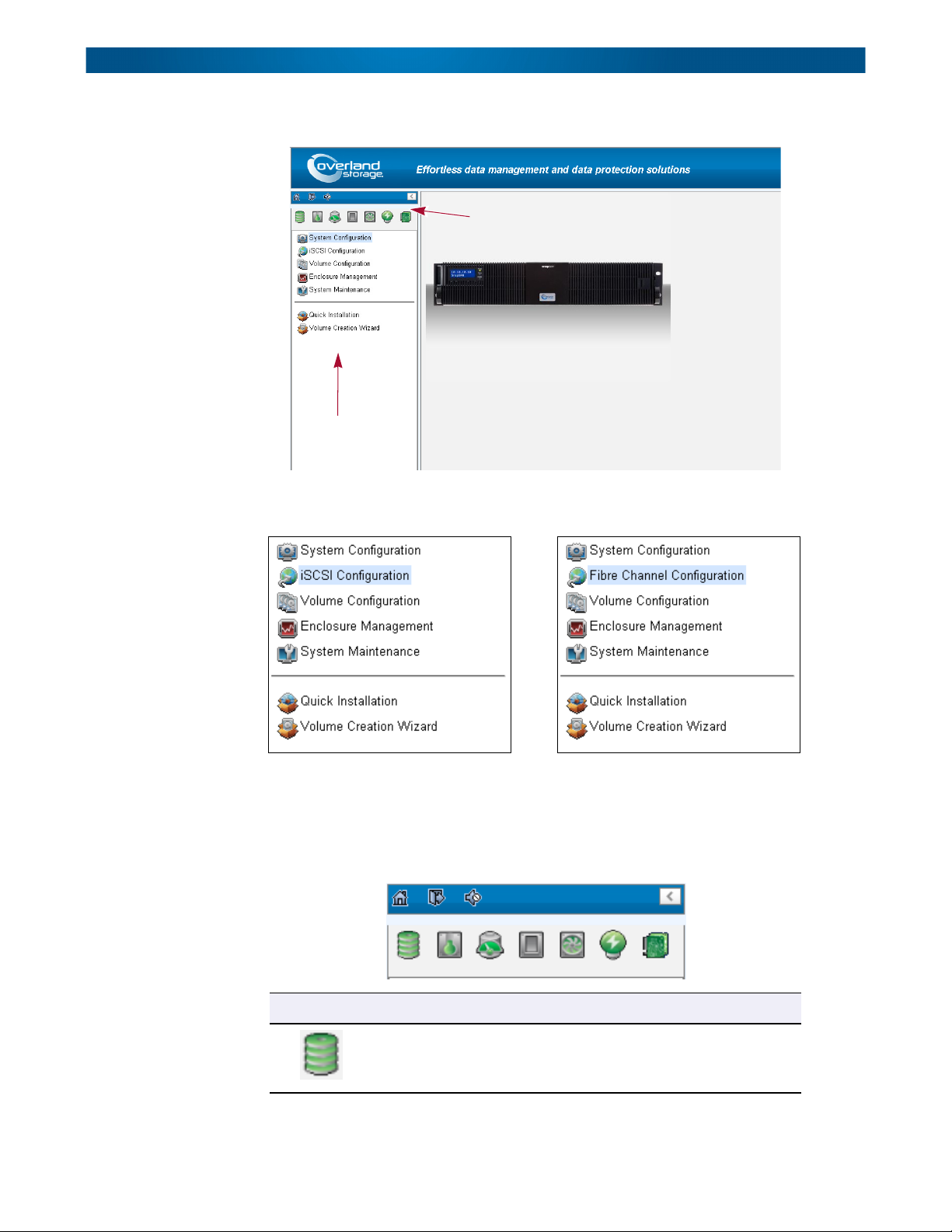
When the password has been verified, the Home Page is displayed.
Indicators
and Icons
(Content Page)
Menu Bar
Options
Choose the functions from the Menu Bar on the left side of the window to make any
configuration changes. The second item changes based on the type of controllers:
NOTE: The iSCSI Configuration menu bar option is only shown when iSCSI controllers are used in
the S1000. The Fibre Channel Configuration menu appears for Fibre Channel controllers.
There are up to seven indicators and three icons above the Menu Bar. The last indicator
(Dual Controller) is only visible when two controllers are installed.
Icon Description
RAID light:
Green = All RAID Groups are functioning.
Red = A RAID Group is degraded or has failed.
10400310-003 01/2013 ©2010-13 Overland Storage, Inc. 3-2
Page 24

SnapSAN S1000 User Guide Management Interfaces
Icon Description
Temperature light:
Green = Temperature is normal.
Red = Temperature is high.
Voltage light:
Green = Internal power levels are normal.
Red = Internal power levels are abnormal.
UPS light:
Green = UPS functioning or no UPS connected.
Red = UPS connection has failed.
Fan light:
Green = Fan working.
Red = Fan failed.
Power light:
Green = Both power supplies are connected and working.
Red = A power supply has failed or is no longer connected.
Dual controller light:
Green = Dual controllers are active and functioning.
Orange = One of the dual controllers has failed.
Return to Home Page.
Log out of the Management GUI.
Mute alarm beeper.
Tip: Internet Explorer users: If the status indicators in Internet Explorer (IE) are displayed in gray,
but not in blinking red, please enable Tools > Internet Options > Advanced > Play animations
in web pages options in IE. The default value is enabled, but some applications disable it.
For detailed information on the Web Management Interface, see Chapter 4, “Web
Management Interface.”
Front Panel Display
NOTE: The Front Panel Display bottom row of buttons are only accessible with the bezel removed.
After booting up the system, the Front Panel Display on the front of the unit shows the
management port IP and “SnapSAN.”
10400310-003 01/2013 ©2010-13 Overland Storage, Inc. 3-3
Page 25
SnapSAN S1000 User Guide Management Interfaces
To access the Front Panel Display options, press the Enter (ENT) button. Use the Up (▲) and
Down (▼) arrows to scroll through the functions:
• System Info – Displays the firmware version and amount of RAM.
• Alarm Mute – Mutes an alarm after an Error occurs.
• Reboot/Shutdown – Reboots or shutdowns the system.
• Quick Install – Provides steps to create a RAID Group.
• Volume Wizard – Provides steps to create a volume.
• View IP Setting – Displays current IP address, subnet mask, and gateway.
• Change IP Config – Sets IP address, subnet mask, and gateway. There are 2 options:
DHCP (Get IP address from DHCP server) or static IP.
• Enclosure Mgmt – Shows the enclosure data for disk drive temperatures, fan status,
and the power supply status.
• Reset to Default – Resets the SnapSAN S1000 to default settings.
The default resets include Administration password set to “admin,” IP address type set
to “DHCP,” the DHCP default IP address set to “192.168.10.50,” subnet mask set to
“255.255.255.0,” and gateway set to “192.168.10.254.”
Warning or Error events displayed on the Front Panel Display are automatically filtered by
the Front Panel Display default filter. It can be changed in the Web Management Interface
under System Configuration > Log and Alert Settings.
10400310-003 01/2013 ©2010-13 Overland Storage, Inc. 3-4
Page 26
SnapSAN S1000 User Guide Management Interfaces
Front Panel Display Menu Hierarchy
Main Level 1 Level 2 Level 3 Level 4 Level 5
[Firmware Version
[System Info]
[Alarm Mute] [▲Yes No▼]
[Reboot/Shutdown]
[Quick Install]
(only available
if not already set)
[Volume Wizard]
(only available
if not already set)
[<IP Addr>]
SnapSAN
▲ ▼
[View IP Setting]
[Change IP Config]
[Enclosure Mgmt]
[Reset to Default] [▲Yes No▼]
2.0.2]
[RAM Size nnnnMB]
[Reboot] [▲Yes No▼]
[Shutdown] [▲Yes No▼]
RAID 0
RAID 1
RAID 3
RAID 5
RAID 6
RAID 0+1
nnn GB
[Head Unit]
RAID 0
RAID 1
RAID 3
RAID 5
RAID 6
RAID 0+1
[JBOD n] ▲ ▼
RAID 0
RAID 1
RAID 3
RAID 5
RAID 6
RAID 0+1
[IP Config]
[Static IP] or [DHCP]
[IP Address]
[192.168.010.050]
[IP Subnet Mask]
[255.255.255.0]
[IP Gateway]
[192.168.010.254]
[DHCP] [▲Yes No▼]
[BOOTP] [▲Yes No▼]
[Static IP]
[Phy Disk Temp]
[Cooling]
[Power Supply]
[Apply The
Config]
[Use Default
Algorithm]
[New n Disk]
▲ ▼
nnn GB
[IP Address] Adjust IP Address
[IP Subnet Mask]
[IP Gateway]
[Apply IP Setting] [▲Yes No▼]
[Local]
Slot n:nn (C)
[Local (Q212)]
FANn:nnnnn RPM
[Local]
PSUn:<status>
[▲Yes No▼]
[Volume Size]
nnn GB
Adjust Volume
Size
Adjust Submask
IP
Adjust Gateway
IP
[Apply The
Config]
[▲Yes No▼]
[Apply The
Config]
[▲Yes No▼]
10400310-003 01/2013 ©2010-13 Overland Storage, Inc. 3-5
Page 27

SnapSAN S1000 User Guide Management Interfaces
CAUTION: To prevent data loss, when powering down the SnapSAN S1000, perform a normal
shutdown (Reboot/Shutdown > Shutdown > Yes) to flush any data from the cache to the
physical disks, as opposed to simply turning the power OFF.
Front Panel Display Usage
Press the ENT button to access the options shown in the next column to the right. Use the ▲
and ▼ buttons to move up and down the list.
Press ESC to return to the next higher level shown in the column to the left.
At an option that requires a Yes or No response (▲Yes No▼), press the ▲ button for Yes
and the ▼ button for No.
To change IP addresses, use ▲ to increase the number, ▼ to decrease the number, ENT to
move to the right, and ESC to move to the left. After changing the last digit on the right,
press ENT to accept the change and return to the higher level.
Serial Console
Should the need arise, use the provided console cable (NULL modem cable) to connect from
console port of the SnapSAN S1000 to the RS-232 port of management computer. The
console settings are:
Baud rate: 115200, 8 data bit, no parity, 1 stop bit, and no flow control.
Terminal type: vt100
Login name: admin
Default password: admin
Secure Shell Remote Access
If desired, SSH (secure shell) software can be also used for remote login.
Host name: The DHCP address from the Front Panel Display
Login name: admin
Default password: admin
Tip: When using SSH, the IP address and password are required for login.
10400310-003 01/2013 ©2010-13 Overland Storage, Inc. 3-6
Page 28
Chapter 4
The Web Management Interface is a web-based GUI accessed through your browser. This
chapter reviews all the options available in the Web Management Interface. Refer to “Web
Management Interface” on page 3-1 for details on logging in and using the interface.
Interface Hierarchy
This table shows the hierarchy of the Web Management Interface:
Menu Bar Item Level 1 Level 2, Button, or Menu (▼)
System Configuration System Settings System Name / Date and Time / System Identification
Fibre Channel
Configuration
(This option is only
visible when using
Fibre Channel
controllers)
iSCSI Configuration
(This option is only
visible when using
iSCSI controllers)
Web Management Interface
Network Settings MAC Address / IP Address / DNS Server Address /
Service Ports
Login Settings Login Options / Admin Password / User Password
Email Notification
Settings
Log and Alert Settings SNMP Trap Settings / Windows Messenger / Syslog Server
Fibre Channel Change the link speed.
Network Setup Menu options: iSCSI Bonding Settings / iSCSI IP Address
Entity and iSNS
Settings
iSCSI Nodes Menu options: Authentication Method / Change Portal /
Active Sessions Menu options: List Connections / Delete
CHAP Accounts Menu options: Modify User Information / Delete
Email Settings
Settings / Admin Interface and Front Display Alerts / Device
Buzzer
Settings / Make Default Gateway / Enable Jumbo Frames /
Ping Host
Link Aggregation button: Bonding Method / IP Address /
Subnet Mask / Gateway / Network Setup
Entity Name / iSNS IP Address
Rename Alias/ Users
Create button: User Name / Secret / Re-type Secret / Nodes
10400310-003 01/2013 ©2010-13 Overland Storage, Inc. 4-1
Page 29

SnapSAN S1000 User Guide Interface Hierarchy
Menu Bar Item Level 1 Level 2, Button, or Menu (▼)
Volume Configuration Physical Disks Menu options: Set Free Disk / Set Global Spare / Set
Dedicated Spare / Upgrade / Disk Scrub / Turn On (Off) the
Indication LED / More Information
RAID Groups Menu options: Migrate RAID Level / Move RAID Level /
Activate / Deactivate / Verify Parity / Delete / [Change
Preferred Controller] / Change RAID Options / More
Information
NOTE: Change Preferred Controller option is only shown
when two controllers are installed.
Create button: Create RAID Group dialog box
Virtual Disks Menu options: Extend / Verify Parity / Delete / Set Properties
/ Attach LUN / Detach LUN / List LUNs / Set Clone / Set
Snapshot Space / Cleanup Snapshots / Take a Snapshot /
Scheduled Snapshots / List Snapshots / More Information
Create button: Create a Virtual Disk dialog box
Cloning Options button: Snapshot Space / Threshold / Restart
the task an hour later if failed
Snapshots Set Snapshot Space button: Virtual Disk / Size / Free Capacity
Scheduled Snapshots button: Months to Take Snapshots /
Weeks to Take Snapshots / Days to Take Snapshots / Hours
to Take Snapshots
Take a Snapshot button: Virtual Disk / Snapshot Name
Cleanup Snapshots button
Logical Units Attach button: Virtual Disk / Allowed Hosts / Target / LUN /
Permission
Menu options (when LUN attached): Delete
Enclosure
Management
System Maintenance System Information (Information tables shown for the unit selected)
Quick Installation
Tool
Hardware Monitor Controller 1 Monitors / Controller 2 Monitors / Internal
Monitors / Auto Shutdown
UPS UPS Type / Shutdown Battery Level (%) / Shutdown Delay
(Seconds) / Shutdown UPS / UPS Status / UPS Battery Level
SES Enable (Disable)
S.M.A.R.T. S.M.A.R.T. Information (Only for SATA disk drives)
Event Log Event Log Level to Show / Download / Mute / Clear
Upgrade RAID Controller/Systems / JBOD Controller/Systems /
Controller Mode
Firmware
Synchronization
Reset to Factory
Defaults
Configuration Backup Import or Export / Import File
Reboot and
Shutdown
(Four step wizard. See “Quick Installation Tool” on page 4-40 for details.)
NOTE: Only shown when dual controllers are installed.
Synchronize the Slave Controller’s Firmware Version with the
Master’s version.
(Reset button)
(Reboot button) / (Shutdown button)
10400310-003 01/2013 ©2010-13 Overland Storage, Inc. 4-2
Page 30
SnapSAN S1000 User Guide System Configuration
Menu Bar Item Level 1 Level 2, Button, or Menu (▼)
Volume Creation
Wizard
(Three step wizard. See “Volume Creation Wizard” on page 4-42 for details.)
System Configuration
The System Configuration menu option is for accessing the System Settings, Network
Settings, Login Settings, Email Notification Settings, and Log and Alert Settings option
tabs.
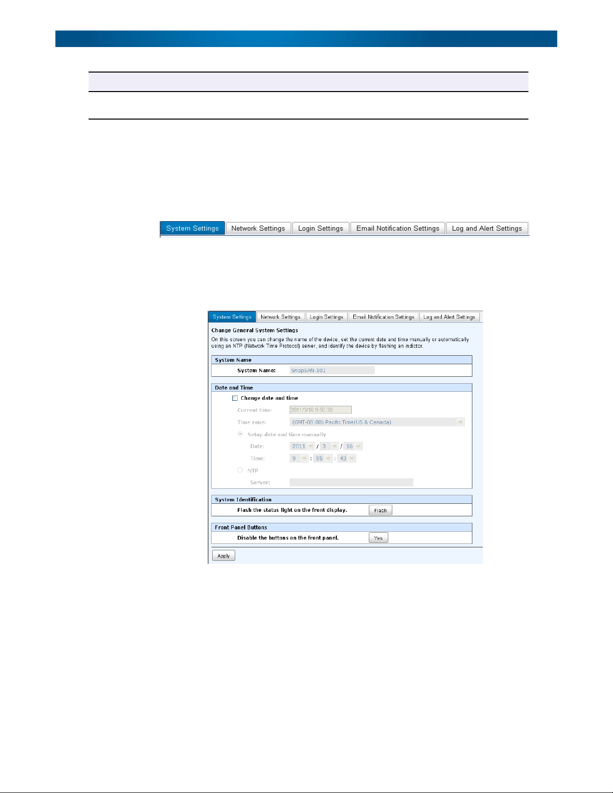
System Settings
The System Settings tab on the System Configuration screen is used to setup the system
name and date. The default System Name is the SnapSAN model name.
Options available on this screen:
• To change the System Name, highlight the old name and type in a new one.
• To change the current date, time, and time zone settings, check Change Date And
Time. The changes can be done manually or you can synchronize the time from an
NTP (Network Time Protocol) server.
• To locate this server in the racks, click the Flash button in the System Indication
section to flash the array’s drive LEDs. Click it again to turn them off.
• To disable the Front Panel Display buttons, click Yes in that section.
When done, click Apply.
10400310-003 01/2013 ©2010-13 Overland Storage, Inc. 4-3
Page 31

SnapSAN S1000 User Guide System Configuration
Network Settings
The Network Settings tab on the System Configuration screen allows you to view the MAC
address and change basic network settings:
• IP Address – change the address used for remote access by an administrator. There are
three address options: DHCP (default), BOOTP, and Specify a Static IP Address.
• DNS Server Address – If necessary, the IP address of the DNS server can be entered or
changed here.
• Service Ports – If the default HTTP, HTTPS, and SSH port numbers are not allowed on
your network, they can be changed here.
Login Settings
The Login Setting tab on the System Configuration screen is used to control access to the
SnapSAN S1000. Use it to set an auto logout time, to limit access to just one administrator
at a time, and to change the Admin and User passwords.
10400310-003 01/2013 ©2010-13 Overland Storage, Inc. 4-4
Page 32

SnapSAN S1000 User Guide System Configuration
The specific options available are:
• Login Options:
• Auto Logout – Choose from Disabled, 5 minutes, 30 minutes, or 1 hour. The
system automatically logs the user out of the Web Management Interface when
they are inactive for the stated period of time.
• Login Lockout – Choose either Disabled or Enabled. When the login lock is
enabled, the system allows only one user to login to the Web Management Interface
at a time.
• Admin Password – Check Change Admin Password to change the administrator
password. The maximum password length is 12 alphanumeric characters or spaces.
• User Password – Check Change User Password to change the user password. The
maximum length of a password is 12 alphanumeric characters or spaces.
Email Notification Settings
The Email Notification Settings on the System Configuration screen is used to enter up to
three email addresses for receiving event notifications. Fill in the necessary fields and click
Send Test Email to test whether email functions are available.
NOTE: Some email servers check the From Email Address and need authentication for anti-spam.
You can also select which levels of event logs you would like to include with the email. The
default setting only includes Warning and Error event logs.
Log and Alert Settings
Log and Alert Settings on the System Configuration screen are used to configure SNMP
traps (for alerting via SNMP), pop-up messages via Windows Messenger (not MSN), alerts
via the syslog protocol, and the event log filter. The unit buzzer is also managed here.
10400310-003 01/2013 ©2010-13 Overland Storage, Inc. 4-5
Page 33

SnapSAN S1000 User Guide System Configuration
• SNMP Trap Settings – The SnapSAN S1000 allows up to three SNMP trap
addresses. The default community setting is public. You can choose the SNMP alert
levels you want to receive. The default setting is for only Warning and Error alerts.
There are many SNMP tools available on the web including:
• SNMPc: http://www.snmpc.com/
• Net-SNMP: http://net-snmp.sourceforge.net/
• Windows Messenger – You must enable the Messenger service in Windows (Start >
Control Panel > Administrative Tools > Services > Messenger) for alerts to be
received. The SnapSAN S1000 allows up to three Messenger addresses. You can choose
the messenger alert levels you want to receive. The default setting is for only Warning
and Error alerts.
• Syslog Server Settings – The default port of syslog is 514. You can choose the system
alert levels you want to have logged. The default setting is for only Warning and Error
alerts.
There are syslog server tools available on the web for Windows including:
• WinSyslog: http://www.winsyslog.com/
• Kiwi Syslog Daemon: http://www.kiwisyslog.com/
Most UNIX systems build in syslog daemon.
• Admin Interface and Front Panel Display Alerts – You can choose the alert levels
you want to have pop up in the Web Management Interface and shown on the Front
Panel Display. The default setting for the Web Management Interface is no alerts
while the default setting for the Front Panel Display is for only Warning and Error
alerts.
• Device Buzzer – Check the box to disable the buzzer. Uncheck it to reactivate the
buzzer.
10400310-003 01/2013 ©2010-13 Overland Storage, Inc. 4-6
Page 34

SnapSAN S1000 User Guide Fibre Channel Configuration
Fibre Channel Configuration
IMPORTANT: This section is only visible when one or more of the Fibre Channel controller
modules are used in the SnapSAN S1000.
The Fibre Channel menu option lets you access the Fibre Channel tab to change the link
speed. Click the Fibre Channel menu button (▼) next to the port name to access the option
to change the link speed for that particular port.
iSCSI Configuration
IMPORTANT: This section is only visible when one or more of the iSCSI controller modules are
used in the SnapSAN S1000.
The iSCSI Configuration menu option is for accessing the Network Setup, Entity and iSNS
Settings, iSCSI Nodes, Active Sessions, and CHAP Accounts option tabs.
Network Setup
The Network Setup tab on the iSCSI Configuration screen is used to change IP addresses of
iSCSI data ports. A SnapSAN S1000 with iSCSI gigabit controllers has four ports on each
controller to transmit data. Each port must be assigned its own IP address. They need to be
configured in multi-homed mode or a preset link aggregation / trunking mode. When
multiple iSCSI data ports are set up in link aggregation or trunking mode, all the data ports
share a single IP address.
NOTE: This figure shows four iSCSI data ports on each controller. The four 1Gb data ports are set
up with a static IP address. For iSCSI 10Gb controllers, each controller has two optical ports
that can be set up the same way.
10400310-003 01/2013 ©2010-13 Overland Storage, Inc. 4-7
Page 35

SnapSAN S1000 User Guide iSCSI Configuration
Clicking the menu button (▼) displays the options for each LAN:
iSCSI Bonding Settings
The default mode of each iSCSI data port is that it is individually connected (multi-homed)
without any link aggregation and trunking. This function is also for Multipath functions.
Trunking and LACP (Link Aggregation Control Protocol) settings can be set or changed by
selecting the iSCSI Bonding Settings menu option from the drop-down list. Select the
bonding method and its options:
• Trunking – Configures multiple iSCSI data ports to act in parallel to increase the link
speed beyond the limits of any single port.
• LACP – This is part of the IEEE specification 802.3ad that allows several physical
ports to be bundled together to form a single logical channel. This increases the
bandwidth and provides automatic failover when link status fails on a port.
NOTE: You must select at least two iSCSI NICs for iSCSI bonding to work.
To remove a Trunking or LACP setting, click the menu button (▼) for the specific LAN port
and select Delete Link Aggregation. Click OK at the confirmation message.
For example, LAN1 and LAN2 are set as Trunking mode. LAN3 and LAN4 are set as LACP
mode.
NOTE: After removing the bonding, the secondary LAN is reset to use a static IP address but no
address is configured. You must manually reset the address.
10400310-003 01/2013 ©2010-13 Overland Storage, Inc. 4-8
Page 36

SnapSAN S1000 User Guide iSCSI Configuration
iSCSI IP Address Settings
To change an iSCSI IP address, click the menu button (▼) for the LAN port and select iSCSI
IP Address Settings. There are two options: DHCP or Static. You can select DHCP to acquire
an IP address automatically or Static to set the IP address manually:
Default Gateway
The default gateway can be changed by clicking the menu button (▼) for the LAN port that
you want as the gateway and selecting Make Default Gateway. There can be only one
default gateway.
To remove the default gateway, click the menu button (▼) of the LAN that is currently the
gateway, and select Remove Default Gateway.
Jumbo Frames (MTU)
The MTU (Maximum Transmission Unit) size can be enabled by clicking the menu button
(▼) of a LAN port and then clicking Enable Jumbo Frames. Maximum jumbo frame size is
9000 bytes.
CAUTION: Jumbo frames for both the switching hub and HBA on the host computer must be
enabled. Otherwise, the LAN connection will not work properly.
To disable jumbo frames, click the menu button (▼) of the LAN that uses jumbo frames, and
select Disable Jumbo Frames.
10400310-003 01/2013 ©2010-13 Overland Storage, Inc. 4-9
Page 37

SnapSAN S1000 User Guide iSCSI Configuration
Ping Host
To verify that the port connection from a target to the corresponding host data port is good,
click Ping Host. Enter the IP address and click Start. The unit sends out six pings (or you can
stop it by clicking Stop).
Entity and iSNS Settings
Use Entity and iSNS Settings tab on the iSCSI Configuration screen to view or change the
entity name of the system and setup an iSNS IP for the iSNS (Internet Storage Name
Service) protocol.
The entity name is a name for a device or gateway that is accessible from the iSCSI network.
Initiator
Network Entity
iSCSI Node
(Initiator)
Network
Portal
IP Address
TCP Port No.
iSCSI
Session
iSCSI Node
(Initiator)
Network
Portal
IP Address
TCP Port No.
Target
Network Entity
iSCSI Node
(Initiator)
Network
Portal
IP Address
TCP Port No.
The iSNS protocol allows automated discovery, management, and configuration of iSCSI
devices on a TCP/IP network. To use iSNS, an iSNS server needs to be added to the SAN.
Once this is done, the iSNS server IP address must be added to the SnapSAN S1000 for the
iSCSI initiator service to send queries to it.
To make changes, enter the Entity Name and the iSNS IP Address, then click Apply.
10400310-003 01/2013 ©2010-13 Overland Storage, Inc. 4-10
Page 38

SnapSAN S1000 User Guide iSCSI Configuration
iSCSI Nodes
The iSCSI Node tab on the iSCSI Configuration screen is used to view the target name for
iSCSI initiators. SnapSAN S1000 supports up to 32 nodes on each controller.
Clicking the menu button (▼) displays the options for each initiator.
Authentication Method
CHAP (Challenge Handshake Authentication Protocol) is a strong authentication method
used in point-to-point for user login. It’s a type of authentication in which the authentication
server sends the client a key to be used for encrypting the user name and password. CHAP
enables the user name and password to transmit in an encrypted form for protection.
IMPORTANT: A CHAP account must be active before you can use this authentication method.
Please refer to “CHAP Accounts” on page 4-15 to create an account if one doesn’t exist.
To use CHAP authentication:
1. Select one of 32 default nodes from one controller.
2. Click the menu button (▼) and select Authentication Method.
10400310-003 01/2013 ©2010-13 Overland Storage, Inc. 4-11
Page 39

SnapSAN S1000 User Guide iSCSI Configuration
3. Select CHAP from the drop-down list:
4. Click OK to change the Authentication Method (Auth) to CHAP:
5. Click the menu button (▼) again and select Users.
6. Select all the CHAP users which will be used.
It can be more than one, but it must be at least one for CHAP to work.
7. Click OK.
To delete the CHAP authentication, from the drop-down menu, select Authentication
Methods and change it to None.
Tip: After setting CHAP authentication, the host initiator should be set with the same CHAP
account. Otherwise, a user cannot login.
Change Portal
Use this iSCSI Node option to change the network ports available:
1. Click the menu button (▼) of the node and select Change Portal.
10400310-003 01/2013 ©2010-13 Overland Storage, Inc. 4-12
Page 40

SnapSAN S1000 User Guide iSCSI Configuration
2. Check the portals you want for the controller:
3. Click OK.
Rename Alias
This option is used to create an alias to one device node. To add or change an alias name,
enter the name and click OK. To delete the alias, clear the current name and click OK.
After creating an alias, it is shown at the end of the portal information.
Users
Select the CHAP users for access to the highlighted node. CHAP users must previously have
been created.
Active Sessions
The Active Sessions tab on the iSCSI Configuration screen displays all currently active
iSCSI sessions and their connection information.
10400310-003 01/2013 ©2010-13 Overland Storage, Inc. 4-13
Page 41

SnapSAN S1000 User Guide iSCSI Configuration
Clicking the menu button (▼) displays the options for each session.
This table shows the column descriptions for this tab. Most of the options are standard
parameters used in the negotiation between the initiator and target when a iSCSI
connection is created:
Column Name Description
TSIH (Target Session Identifying Handle) The name used for this
active session.
Initiator Name The host computer name
Target Name The controller name
InitialR2T (Initial Ready to Transfer) This is used to turn off either the use
of a unidirectional R2T command or the output part of a
bidirectional command.
Default: Yes.
Immed. Data (Immediate Data) This sets the support for immediate data
between the initiator and the target. Both must be set to the
same setting.
Default: Yes.
MaxDataOutR2T (Maximum Data Outstanding Ready to Transfer) This is the
MaxOutstanding R2T setting which determines the maximum
number of outstanding R2Ts per task.
Default: 1.
MaxDataBurstLen (Maximum Data Burst Length) This determines the maximum
SCSI data payload.
Default: 256Kb.
DataSeqInOrder (Data Sequence in Order) This determines if the Protocol Data
Units (PDUs) are transferred in continuously non-decreasing
sequence offsets.
Default: Yes.
DataPDUInOrder (Data PDU in Order) This determines if the data PDUs within
sequences are to be in order and overlays forbidden.
Default: Yes.
Detail of
Authentication Status
and Source IP:
<port#>
More information about Port <#>.
10400310-003 01/2013 ©2010-13 Overland Storage, Inc. 4-14
Page 42

SnapSAN S1000 User Guide iSCSI Configuration
Click the menu button (▼) of session number and select Connection Details. It lists all
connections of that session.
To terminate a session, click the menu button (▼) and select Disconnect. Click OK to
confirm.
CHAP Accounts
The CHAP Accounts tab on the iSCSI Configuration screen displays all CHAP Users
configured on the system.
Clicking the menu button (▼) displays the options for each user.
Use CHAP Accounts to create a CHAP account for system user authentication. A SnapSAN
S1000 can have multiple CHAP accounts.
To create a CHAP account:
1. Click Create User. The creation dialog box opens.
2. Enter data for User, Secret, and Confirm (secret).
10400310-003 01/2013 ©2010-13 Overland Storage, Inc. 4-15
Page 43

SnapSAN S1000 User Guide iSCSI Configuration
3. If desired, select one or more nodes.
If selecting none, they can be added later by going to iSCSI configuration > Node >
User.
4. Click OK.
To modify a CHAP account, click the menu button (▼) of the account and select Modify
User Information. Enter the new data and click OK.
NOTE: To change the nodes accessible by this user, go to iSCSI Configuration > iSCSI Node. To add
the user, click the menu button for that node, and select the user. To delete the user, click
the menu button for that node and uncheck the user.
To delete a CHAP account, click the menu button (▼) of the account and select Delete User.
At the confirmation message, click OK.
10400310-003 01/2013 ©2010-13 Overland Storage, Inc. 4-16
Page 44

SnapSAN S1000 User Guide Volume Configuration
Volume Configuration
The Volume Configuration menu option is for accessing the Physical Disks, RAID Groups,
Virtual Disks, Snapshots, and Logical Units option tabs.
Physical Disks
The Physical Disks tab on the Volume Configuration screen provides the status of the disk
drives in the system. The two drop-down lists at the top enable you to switch between the
head unit and any expansion units attached and to change the drive size units (MB and GB).
This table shows the column descriptions for this tab:
Column Name Description
Slot The slot position of a disk drive. See “Drive Slot Numbering” on
page 2-3 for details.
Size (GB) [or (MB)] Capacity of the disk drive. The number can be displayed in GB
or MB (depending on the size setting).
RAID Group RAID Group name.
Status The status of the disk drive:
• Online – The disk drive is online.
• Rebuilding – The disk drive’s data is being rebuilt.
• Transition – The disk drive’s data is being migrated or is
replaced by another disk.
• Scrubbing – The disk drive’s data is being scrubbed.
Health The health of disk drive:
• Good – The disk drive is functioning normally.
• Failed – The disk drive has failed.
• Error Alert – S.M.A.R.T. error detected.
• Read Errors – The disk drive has had an unrecoverable read
error.
Usage The usage of disk drive:
• RAID – This disk drive is part of a RAID Group.
• Free – This disk drive is free for use.
• Dedicated spare – This disk drive is set up as dedicated
spare of a RAID Group.
• Global spare – This disk drive is set up as global spare for any
RAID Group.
Vendor The disk drive vendor.
10400310-003 01/2013 ©2010-13 Overland Storage, Inc. 4-17
Page 45

SnapSAN S1000 User Guide Volume Configuration
Column Name Description
Interface The disk drive type:
• SATA2 – It is a SATA II disk.
• SAS – It is a SAS disk.
Menu options for the Physical Disks tab are accessed by clicking the menu button (▼). Active
functions can be selected while inactive functions appear grayed out and cannot be selected.
This table shows the available functions and their descriptions:
RAID Groups
The RAID Groups tab on the Volume Configuration screen enables you to create, modify, or
view the status of the RAID Groups. Use the drop-down list at the top to change the drive
size units (MB or GB).
Menu Item Description
Set Free Disk Make the selected disk drive available for use.
Set Global Spare Set the selected disk drive to global spare of all RAID Groups.
Set Dedicated Spare Set a disk drive to dedicated spare of the selected RAID Group.
Upgrade Upgrade the firmware on selected disks.
Disk Scrub Scrub the disk drive.
Turn On/Off the
Indication LED
More Information Show disk drive detail information.
Turn on the indication LED of the disk drive. Click again to turn it
off.
This table shows the column descriptions for this tab:
Column Name Description
Name The RAID Group name.
10400310-003 01/2013 ©2010-13 Overland Storage, Inc. 4-18
Page 46

SnapSAN S1000 User Guide Volume Configuration
Column Name Description
Total (GB) [or (MB)] The total capacity of this RAID Group. The number can be
displayed in GB or MB (depends on the size setting).
Free (GB) [or (MB)] The free capacity of this RAID Group. The number can be
displayed in GB or MB (depends on the size setting).
Disks Used The number of physical disks in a RAID Group.
Number of Virtual
Disks
Status The status of RAID Group:
Health The health of RAID Group:
RAID The RAID type of the RAID Group.
Current Controller NOTE: This option only appears with dual controllers.
Preferred Controller NOTE: This option only appears with dual controllers.
The number of virtual disks using this RAID Group.
• Online – The RAID Group is online and functioning normally.
• Offline – The RAID Group is offline.
• Rebuild – The RAID Group is being rebuilt.
• Migrate – The RAID Group is being migrated.
• Scrubbing – The RAID Group is being scrubbed.
• Good – The RAID Group is working normally with all disk drives.
• Failed – The RAID Group is no longer functional.
• Degraded – The RAID Group has lost a disk drive and is no
longer at the desired level.
The controller to which the RAID Group is currently assigned.
Default: Controller 1.
The controller that is the preferred manager of the RAID Group.
Default: Controller 1.
Menu options for RAID Groups are accessed by clicking the menu button (▼). Active
functions can be selected while inactive functions appear grayed out and cannot be selected.
This table shows the available functions and their descriptions:
Menu Item Description
Migrate RAID Level Change the RAID level of a RAID Group. Please refer to “Migrate a
RAID Level” on page 4-21.
10400310-003 01/2013 ©2010-13 Overland Storage, Inc. 4-19
Page 47

SnapSAN S1000 User Guide Volume Configuration
Menu Item Description
Move RAID Level Use this option to move the RAID from one set of disk drives to
another.
Activate Activate the RAID Group after disk roaming. It can be executed
when the RAID Group status is offline.
Deactivate Deactivate the RAID Group before disk roaming. It can be
executed when RAID Group status is online.
Verify Parity Regenerate parity for the RAID Groups that support parity drives
(RAID 3 / 5 / 6 / 30 / 50 / 60).
Delete Delete the RAID Group.
Change Preferred
Controller
Change RAID Options Change the disk properties of the RAID:
More Information Show detailed information for a RAID Group.
NOTE: This option only appears with dual controllers.
Set the RAID Group ownership to the other controller.
• Write Cache – Cache Enabled (default) / Disabled.
• Standby – Disabled (default) / Enabled. Disk drive auto
spindown is used to save power when not accessed after a
certain period of time (30 sec / 1 min. / 5 min. / 30 min.).
NOTE: Using the Standby option may cause some applications
to time out while they wait for the disks to spin back up.
• Read-Ahead – Disk read-ahead feature Enabled (default) /
Disabled.
• Command Queuing – Disk command queue Enabled (default)
/ Disabled.
Create a RAID Group
1. Click the Create button.
2. Use the Create RAID Groups dialog to configure the group:
• Enter a RAID Name for the group.
• Use the drop-down list to select a RAID Level.
• Click the Select Disks button, select disks from either the Head Unit or
Expansion units for use, and click OK to complete the selection. The selected disks
are shown under Disks Used.
10400310-003 01/2013 ©2010-13 Overland Storage, Inc. 4-20
Page 48

SnapSAN S1000 User Guide Volume Configuration
• Optionally, configure the following:
• Write Cache usage.
• Standby option.
• Read-Ahead option.
• Command Queuing option.
3. Click OK to create the RAID Group.
4. At the confirmation message, click OK.
Migrate a RAID Level
1. Select Migrate RAID Level from the menu.
2. Configure the options:
• Enter a RAID Name.
• From the drop-down list, select the new RAID Level.
• Click the Select Disks button, select disks from either the Head Unit or
Expansion units for use, and click OK to complete the selection. The selected disks
are shown under Disks Used.
3. Click OK to complete the RAID migration.
Move RAID Level
1. Select Move RAID Level from the menu.
2. Configure the options:
• Enter a RAID Name.
• From the drop-down list, select the new RAID Level.
10400310-003 01/2013 ©2010-13 Overland Storage, Inc. 4-21
Page 49

SnapSAN S1000 User Guide Volume Configuration
• Click the Select Disks button, select disks from either the Head Unit or
Expansion units for use, and click OK to complete the selection. The selected disks
are shown under Disks Used.
3. Click OK to complete the RAID move.
Virtual Disks
The Virtual Disks tab on the Volume Configuration screen enables you create, modify, or
view the status of virtual disks. Use the drop-down list at the top to change the drive size
units (MB and GB).
This table shows the column descriptions for this tab:
Column Name Description
Name The virtual disk name.
RAID Group The RAID Group to which the virtual disk belongs.
Size (GB) [or (MB)] The total capacity of the virtual disk. The number can be
displayed in GB or MB (depends on the size setting).
Interface Type of interface (RAID or Backup) used by the virtual disk.
Status Shows the current status of a virtual disk:
• Online – The virtual disk is online and active.
• Offline – The virtual disk is offline.
• Initiating – The virtual disk is being initialized for use.
• Rebuild – The virtual disk is being rebuilt.
• Migrate – The virtual disk is being migrated to a different RAID
level.
• Rollback – The virtual disk is being rolled back to a previous
version.
• Scrubbing – The virtual disk is being scrubbed.
• Parity checking – The virtual disk is being parity check.
Health Shows the health of a virtual disk:
• Optimal (
are no failed disks in the RAID Group.
• Degraded (
by the virtual disk has failed or has been removed.
• Failed (
the virtual disk has failed or has been removed and this is
more than its RAID level can recover from to prevent loss of
data.
• Partially Optimal – The virtual disk has experienced
recoverable read errors.
R % The percent completed of an initializing (or rebuilding) of the
virtual disk.
green) – The virtual disk is working well and there
orange) – At least one disk in the RAID Group used
red) – One or more disks in the RAID Group used by
10400310-003 01/2013 ©2010-13 Overland Storage, Inc. 4-22
Page 50

SnapSAN S1000 User Guide Volume Configuration
Column Name Description
Snapshot Space (GB)
[or (MB)]
Snapshot # The number of snapshots that have been taken of the virtual
Clone The Virtual Disk that the current disk was setup to be cloned
Schedule An icon is used to show the time when clones are scheduled to
The RAID Group space that is used for Snapshots. The number
means used or total Snapshot space. The number can be
displayed in GB or MB (depending on the size setting).
disk.
from. When you have several virtual disks, you can tell one disk
to be the clone of another. The clone process creates a snapshot
of the other virtual disk.
To be able to clone a VD, it must be of the type backup.
run.
Menu options for virtual disks are accessed by clicking the menu button (▼). Active
functions can be selected while inactive functions appear grayed out and cannot be selected:
This table shows the available functions and their descriptions:
Menu Item Description
Extend Extend the virtual disk capacity. The new size must be larger than
the current size. See “Virtual Disk Extension” on page 5-4 for
details.
Verify Parity Verify the parity for the virtual disk. It supports any RAID Group
with a parity disk (3 / 5 / 6 / 30 / 50 / 60).
• Regenerate parity when parity/data inconsistency is found–
Regenerate the RAID parity and write it to the parity disk.
• Check parity/data consistency only– Only verify the parity to
find mismatches. When the mismatch count reaches the
number selected from the drop-down list, the process stops.
Delete Delete the virtual disk.
10400310-003 01/2013 ©2010-13 Overland Storage, Inc. 4-23
Page 51

SnapSAN S1000 User Guide Volume Configuration
Menu Item Description
Set Properties Change the properties of a virtual disk:
• Virtual Disk Name
• Cache Mode
• Priority
• Bg Rate (Background Rate)
• Read-Ahead
Attach LUN Attach a LUN to a virtual disk.
Detach LUN Detach a LUN from a virtual disk.
List LUNs List all LUNs attached to a virtual disk.
Set Clone Use to set the target.
Set Snapshot Space Reserve space for taking snapshots. The minimum size is
suggested to be 20% of the RAID Group size. See more under
“Create the Snapshot Space” on page 5-5.
Cleanup Snapshots Deletes all snapshots of a virtual disk and frees up the snapshot
space for use.
Set Snapshot Space Reserve RAID Group space for snapshots.
Scheduled Snapshots Schedule times for automatic snapshots.
Take a Snapshot Manually create a snapshot.
Cleanup Snapshots Remove/delete all existing snapshot
Create a Virtual Disk
IMPORTANT: If you plan to take snapshots, you must leave space in the RAID Group for the
Snapshot Pool. It is recommended that you leave at least 20% of the space for snapshots and
use the remaining 80% for virtual disks. Refer to “Snapshots” on page 5-4.
This example shows the basic steps needed to create a virtual disk from a RAID Group using
the Create a Virtual Disk dialog:
1. Click the Create button below the table.
10400310-003 01/2013 ©2010-13 Overland Storage, Inc. 4-24
Page 52

SnapSAN S1000 User Guide Volume Configuration
2. Use the Create a Virtual Disk dialog to configure the disk:
• Enter a Volume Name for the virtual disk.
• Use the drop-down list to select a RAID to use.
• Enter the Size and select the size units.
• Use the drop-down list to select a Stripe Size.
• Use the drop-down list to select a Block Size.
• Select a Cache Mode and Priority.
• Choose a Background Rate (Bg Rate) from the drop-down list.
• If desired, change the Read-Ahead Cache setting from the default.
3. Click OK.
4. At the confirmation message, click OK to begin the initialization:
Snapshots
The Snapshots tab on the Volume Configuration screen enables you create, modify, or view
the status of snapshots. Use the drop-down list at the top to change the virtual disk and
drive size units (MB and GB). For more detailed information, refer to “Snapshots” on
page 5-4.
This table shows the column descriptions for this tab:
Column Name Description
No. Lists the snapshot number.
Name Shows the name given to the snapshot.
Used (GB) [or (MB)] Lists the amount of snapshot space that has been used. The
number can be displayed in GB or MB (depending on the disk
size setting).
Status Shows the current status of a virtual disk:
• Replicated – Being cloned or replicated.
• Aborted – Failed to be cloned or replicated.
• Undeletable – Not able to delete the replication.
• N/A – The snapshot status is not available.
Health Provides the health of snapshot:
• Good – The snapshot was successful.
• Failed – The snapshot failed.
10400310-003 01/2013 ©2010-13 Overland Storage, Inc. 4-25
Page 53

SnapSAN S1000 User Guide Volume Configuration
Column Name Description
Exposure Tells if the snapshot was completed or not.
Write Lists the write status of the snapshot:
• Read-write – The snapshot can be read or written to.
• Read-only – The snapshot is read-only.
Cache Mode Displays the type of cache used:
• Read-write – The cache can be read or written to.
• Read-only – The cache is read-only.
LUN # Shows the number of LUN that is attached to the snapshot.
Time Created States the time when the snapshot was created.
Menu options for snapshots are accessed by clicking the menu button (▼). Active functions
can be selected while inactive functions appear grayed out and cannot be selected.
This table shows the available functions and their descriptions:
Menu Item Descriptions
Set Quota Set the size of the snapshot.
Rollback Rollback the snapshot.
Delete Delete all the snapshots.
Attach LUN Attach a LUN to the snapshot.
Detach LUN Detach the LUN from the snapshot.
List LUNs List the attached LUNs.
This table shows the available buttons (under the table) and their descriptions:
Menu Item Descriptions
Set Snapshot Space Reserve RAID Group space for snapshots.
Scheduled Snapshots Schedule times for automatic snapshots.
Take a Snapshot Manually create a snapshot.
Cleanup Snapshots Remove/delete all existing snapshot
IMPORTANT: For complete details and procedures used with SnapShots on a SnapSAN S1000
including automatically scheduled snapshots, refer to “Snapshots” on page 5-4.
Take a Snapshot
1. Click the Take a Snapshot button below the table.
2. Select a Virtual Disk, enter a Snapshot Name, and click OK.
3. Click to the menu button (▼) next to the snapshot number and select Set Quota (size).
10400310-003 01/2013 ©2010-13 Overland Storage, Inc. 4-26
Page 54

SnapSAN S1000 User Guide Volume Configuration
4. Enter the snapshot Size, and click OK.
The size must not exceed the available space. If size is zero, the exposed snapshot will
be read-only. Otherwise, the exposed snapshot can be read or written to and the size
will be the maximum capacity for those rights.
5. Click to the menu button (▼) next to the snapshot number and select Attach LUN.
Wait while the information is accessed.
6. Enter the information requested and click OK.
See “Attach a LUN” on page 4-27 for details.
The snapshot is ready for access.
Logical Units
The Logical Units tab on the Volume Configuration screen enables you create, modify, or
view the status of the attached logical unit numbers for each virtual disk.
NOTE: Although you can log on to any target, you will not see the LUN if the IQN does not match. If
you do not want a host to be able to log on to a target, you should use the CHAP mechanism
to filter out the connection, not the IQN. The IQN is used to control what LUN a host will see
after it has logged on to the target.
This table shows the column descriptions for this tab:
Column Name Description
Allowed Hosts The iSCSI node name for access control or a wildcard (*) for
access by all hosts.
Target The number of the target.
LUN The number of the LUN assigned.
Permissions Shows permission level (Read-only or Read-write).
Virtual Disk The name of the virtual disk assigned to this LUN.
Number of Session The number of the active connection linked to the logical unit.
Attach a LUN
1. Click the Attach LUN button below the table.
10400310-003 01/2013 ©2010-13 Overland Storage, Inc. 4-27
Page 55

SnapSAN S1000 User Guide Volume Configuration
2. At the dialog box, enter or select the options:
a. Select the Virtual Disk from the drop-down list.
b. Enter the Host name.
Each Host must have either an iSCSI node name for access control or a wildcard (*)
to allow access by every host.
c. Select the Target number from the drop-down list.
d. Select the LUN number from the drop-down list.
e. Choose the Permission level.
f. Click OK.
Detach a LUN
Click the menu button (▼) of the LUN being detached and select Delete LUN. Click OK to
confirm.
Volume Creation Example
The following is an example on how to create volumes. This example will create two virtual
disks in one RAID Group with each virtual disk sharing the cache volume. The cache volume
is created after system boots up automatically. Then a global spare disk with be set up. Last,
all of them will be deleted.
Create the Virtual Disks and RAID Groups
1. Create a RAID Group:
a. Go to Volume Configuration > RAID Group.
b. Click Create.
10400310-003 01/2013 ©2010-13 Overland Storage, Inc. 4-28
Page 56

SnapSAN S1000 User Guide Volume Configuration
c. At the Create RAID Group dialog, enter or select the options, using the data in
this graphic.
For Select Disks, choose disks from either the Head Unit or Expansion units for
use, and click OK to complete the disk selection.
d. Verify the settings and click OK to accept.
A RAID Group has been created.
2. Create a virtual disk named “VD-R5-1” using about 40% of the RAID Group:
a. Select the Virtual Disk tab.
b. Click Create.
10400310-003 01/2013 ©2010-13 Overland Storage, Inc. 4-29
Page 57

SnapSAN S1000 User Guide Volume Configuration
c. At the Create a Virtual Disk dialog, enter or select the options.
3. Repeat Step 2 to create another virtual disk named “VD-R5-2” using about 40% of the
RAID Group.
You now have virtual disks named VD-R5-1 and VD-R5-2. There are no LUNs
attached.
4. Attach a LUN to a virtual disk.
There are two methods to attach a LUN to a virtual disk:
• From Volume Configuration > Virtual Disks, click the menu button (▼) next to the
virtual disk number and select Attach LUN.
• From Volume Configuration > Logical Unit, click Attach LUN.
We will use both procedures:
a. Select the Virtual Disks tab.
b. Click to the menu button (▼) next to the virtual disk Name and select Attach
LUN.
c. At the Attach LUN dialog, enter or select the options.
d. Click OK.
e. Select the Logical Unit tab.
10400310-003 01/2013 ©2010-13 Overland Storage, Inc. 4-30
Page 58

SnapSAN S1000 User Guide Volume Configuration
f. Select the second virtual disk.
g. Click Attach LUN.
h. Enter or select the following options:
• Host name of Target 1.
• Target number 1.
• LUN number LUN 1.
• Read-write permissions.
i. Click OK.
VD-R5-1 is now attached to LUN 0 and VD-R5-2 is attached to LUN 1.
Tip: The matching rules of access control are from the LUNs’ created time, the earlier
created LUN is prior to the matching rules.
5. Set a global spare disk:
a. Select the Physical Disk tab.
b. Click the menu button (▼) next to the free Physical Disks slot number and select
Set Global Space.
Delete Virtual Disks and RAID Groups
1. Detach the LUNs from the virtual disks:
a. Select the Logical Unit tab.
b. Click the menu button (▼) next to the first Host name and select Detach LUN.
c. At the confirmation message, click OK.
d. Repeat Steps a–c for the second LUN.
2. Delete the virtual disks:
a. Select the Virtual Disks tab.
b. Click the menu button (▼) next to the first virtual disk and select Delete.
c. At the confirmation message, click OK.
d. Repeat Steps a–c for the second virtual disk.
Tip: When deleting the virtual disks directly, the attached LUNs are detached at the same
time.
3. Delete the RAID Group:
a. Select the RAID Group tab.
b. Verify that all virtual disks for this RAID Group are deleted.
Otherwise, the RAID Group cannot be deleted.
c. Click the menu button (▼) next to the RAID Group Name and select Delete.
10400310-003 01/2013 ©2010-13 Overland Storage, Inc. 4-31
Page 59

SnapSAN S1000 User Guide Enclosure Management
d. At the confirmation message, click OK.
4. Release the Global Spare Disk:
a. Select the Physical Disk tab.
b. Click the menu button (▼) next to the Physical Disks used as the spare and select
Set Free Disk.
All volumes have now been deleted.
Enclosure Management
The Enclosure Management menu option is for accessing the Hardware Monitor, UPS, SES,
and S.M.A.R.T. option tabs.
For the purpose of enclosure management, many different sensors are used (such as,
temperature sensors, voltage sensors, hard disk status, fan sensors, power sensors, and LED
status sensors). Due to the different hardware characteristics among these sensors, they
have different polling intervals:
• Temperature sensors – 1 minute.
• Voltage sensors – 1 minute.
• Hard disk sensors – 10 minutes.
• Fan sensors – 10 seconds. When there are three (3) errors consecutively, the system
logs an error event.
• Power sensors – 10 seconds, when there are three (3) errors consecutively, the system
logs an error event.
• LED status sensors – 10 seconds.
10400310-003 01/2013 ©2010-13 Overland Storage, Inc. 4-32
Page 60

SnapSAN S1000 User Guide Enclosure Management
Hardware Monitor
The Hardware Monitor tab on the Enclosure Management screen shows the information of
current voltages and temperatures, and provides an Auto Shutdown option.
If Auto Shutdown is enabled, the system will shutdown automatically when the internal
power levels or temperature are not with normal levels. For better data protection, it is
recommended to check Auto Shutdown.
For better protection and avoiding single short period of high temperature that could trigger
an automatic shutdown, the system uses rules to gauge if a shutdown is needed. This is done
using several sensors placed on key systems that the system checks every 30 seconds for
preset temperatures:
• The core processor temperature limit is 80º C.
• The iSCSI NIC temperature limit is 65º C.
• The SAS expander and SAS controller temperature limits are 65º C.
When one of these sensors reports a temperature above the threshold for three (3)
continuous minutes, the system automatically shuts down. If a high temperature situation
doesn’t last for at least three minutes, the system will not trigger a shutdown.
10400310-003 01/2013 ©2010-13 Overland Storage, Inc. 4-33
Page 61

SnapSAN S1000 User Guide Enclosure Management
UPS
The UPS tab on the Enclosure Management screen can be used to set up a Uninterruptible
Power Supply (UPS).
Currently, the system only supports and communicates with Smart-UPS systems by APC
(American Power Conversion Corp.). Please review the details from their webbiest:
http://www.apc.com/.
First, connect the system and APC UPS via the included cable for communication. (The
SnapSAN S1000 cable plugs into the APC serial cable that comes with the UPS.) Then set up
the shutdown values (shutdown battery level %) for when the power goes out.
NOTE: UPS systems from other companies will work, but they cannot communicate with the
SnapSAN S1000.
This table shows the available options and their descriptions.
Options Description
UPS Type Select UPS Type.
• Smart-UPS – APC UPS
• None – UPS from other vendors or no UPS.
Shutdown Battery
Level (%)
Shutdown Delay
(Seconds)
Shutdown UPS If you select ON, when power is gone, the UPS will shutdown by
UPS Status The status of UPS:
When below the setting level, system will shutdown. Setting level
to “
0” will disable UPS.
If power failure occurs, and system power can not recover, the
system will shutdown at the time specified. Setting delay to “
will disable the function.
itself after the system successfully shuts down. When the power
comes back, the UPS will start working and notify the unit to start
up. Selecting OFF has no impact on the system.
• Detecting…
• Running
• Unable to detect UPS
• Communication lost
• UPS reboot in progress
• UPS shutdown in progress
• The batteries in the UPS have failed. Please change them
immediately.
0”
10400310-003 01/2013 ©2010-13 Overland Storage, Inc. 4-34
Page 62

SnapSAN S1000 User Guide Enclosure Management
Options Description
UPS Battery Level Current power percentage of battery level.
SES
The SES tab on the Enclosure Management screen addresses the SCSI Enclosure Services,
one of the enclosure management standards. This tab can be used to enable or disable the
management of SES.
To enable the feature:
1. Click the Enable button.
2. At the options screen, enter either an iSCSI node name for access control (or a
wildcard (*) to allow access by every host).
3. Select the Target name from the drop-down list.
The above figures shows SES enabled in LUN 0. Because of the wildcard (*), it can be
accessed from every host.
4. Click OK.
SES client software is available at the following web site:
SANtools: http://www.santools.com/
S.M.A.R.T.
The S.M.A.R.T. tab on the Enclosure Management screen manages the S.M.A.R.T. (SelfMonitoring Analysis and Reporting Technology) diagnostic tool for disk drives. It is used to
deliver a warning in advance of a possible drive failure. S.M.A.R.T. provides users a chance
to take actions before a possible drive failure.
10400310-003 01/2013 ©2010-13 Overland Storage, Inc. 4-35
Page 63

SnapSAN S1000 User Guide System Maintenance
S.M.A.R.T. measures many attributes of the disk drive all the time and inspects the
properties of disk drives which may be close to being out of tolerance. The advanced notice
provided by S.M.A.R.T. can allow users to back up or replace the disk drive in question. This
is better than a disk drive crash while it is writing data or rebuilding another failed disk
drive which would result in data loss.
This tool displays S.M.A.R.T. information of the disk drives. The each column shows number
that is the current S.M.A.R.T. value while the threshold value is shown in parenthesis.
Different disk drive vendors use different threshold values; please refer to disk drive
vendors’ specification for details.
S.M.A.R.T. only supports SATA drives. SAS drives do not have this function and will show
“N/A” in the web page:
System Maintenance
The System Maintenance menu option is for accessing the System Information, Event Log,
Upgrade, Reset to Factory Defaults, Configuration Backup, and Reboot and Shutdown
option tabs.
Dual controllers have an extra option for Firmware Synchronization:
10400310-003 01/2013 ©2010-13 Overland Storage, Inc. 4-36
Page 64

SnapSAN S1000 User Guide System Maintenance
System Information
The System Information tab on the System Maintenance screen is used to display system
information (including CPU type), installed system memory, firmware version, serial
numbers of the controllers, backplane ID, and system status.
Event Log
The Event Log tab on the System Maintenance screen provides a log of event messages.
Choose Info, Warning, or Error levels to display those particular events.
Action Buttons
Three special action buttons are located at the bottom of the screen.
• Click the Download button to save the whole event log as a text file with file name log-
ModelName-SerialNumberDate-Time.txt
• Click the Mute buzzer button to stop system alarms.
• Click the Clear button to clear all event logs.
10400310-003 01/2013 ©2010-13 Overland Storage, Inc. 4-37
.
Page 65

SnapSAN S1000 User Guide System Maintenance
The event log is displayed in reverse order which means the latest events are at the top of
the page. The event logs are saved in the first four disk drives; each disk drive has one copy
of the logs. For one system, there are four copies of event logs to make sure users can check
event log any time when there are failed disks.
Upgrade
IMPORTANT: It is recommended to export your system configuration before upgrading the
firmware. Use the Configuration Backup tab (see page 4-39).
The Upgrade tab on the System Maintenance screen is used to upgrade the SnapSAN S1000
or SnapDisk E1000 firmware. Save a new firmware file named “xxxx.bin” in local disk drive,
click Browse to select the file, click Apply to begin, and click OK at the confirmation
message to start to upgrade firmware.
While upgrading, there is a progress bar running. After the upgrade is finished, the system
must restarted manually (Reboot and Shutdown tab) for the new firmware take effect.
NOTE: Please check the Overland Technical Support website for the latest firmware.
Firmware Synchronization
The Firmware Synchronization tab on the System Maintenance screen is used on dual
controller systems to synchronize the controller firmware versions when the firmware of the
Master controller and the Secondary controller are different. The firmware of Secondary
controller is always changed to match the firmware of the Master controller. It doesn’t
matter if the firmware version of Secondary controller is newer or older than that of the
Master controller.
NOTE: This tab is not visible on single controller systems.
10400310-003 01/2013 ©2010-13 Overland Storage, Inc. 4-38
Page 66

SnapSAN S1000 User Guide System Maintenance
Normally, the firmware versions in both controllers are the same.
Reset to Factory Defaults
The Reset to Factory Defaults tab on the System Maintenance screen allows users to reset
the controller values back to the factory default settings.
The default values are:
• Administrator name – admin
• Password – admin
• IP address type – DHCP
NOTE: Defaults for IP address, subnet mask, and gateway are DHCP provided.
Configuration Backup
The Configuration Backup tab on the System Maintenance screen is used to either save
system configuration values (export) or apply a saved configuration (import).
While the volume configuration settings are available for exporting, to prevent conflicts and
overwriting existing data, they cannot be imported.
Choose what you want to do:
• Import – All system configurations imported (excluding volume configuration).
• Export – All configurations exported to a chosen file.
CAUTION: Import will import all system configurations excluding volume configuration and the
current system configurations will be replaced.
10400310-003 01/2013 ©2010-13 Overland Storage, Inc. 4-39
Page 67

SnapSAN S1000 User Guide How To Use the Guided Configurations
Reboot and Shutdown
The Reboot and Shutdown tab on the System Maintenance screen is used to reboot or
shutdown the system in a controlled manner. Before turning off the unit, it is highly
recommended to use the Shutdown feature to flush the data from cache onto the physical
disks and make sure your data is safe.
How To Use the Guided Configurations
To help get the SnapSAN S1000 up and running quickly, two different guided configuration
tools are available in the Web Management Interface: Quick Installation and Volume
Creation Wizard. If you are an advanced user you can skip these guided configurations.
Quick Installation Tool
This tool on the menu bar manually guides you through the process of setting up basic array
information, configuring network settings, and the creation of a RAID Group on your
SnapSAN S1000:
1. Click Quick Installation from the Menu Bar.
2. At the Step 1 screen, enter a System Name and verify the Date and Time. Click
Next to proceed.
To specify a valid Network Time Protocol (NTP) server, click Change Date and Time,
select NTP, and enter the Server address.
10400310-003 01/2013 ©2010-13 Overland Storage, Inc. 4-40
Page 68

SnapSAN S1000 User Guide How To Use the Guided Configurations
3. At the next screen, confirm or change the Management port information:
If you don’t want to use the default DHCP setting, choose either BOOTP, or Specify a
Static IP Address. If needed, the IP address of the DNS server can be entered here. If
the default HTTP, HTTPS, and SSH port numbers are not allowed on your network,
they can be changed here as well.
4. For iSCSI configurations, use this screen to set up the Data port iSCSI IP address, and
then click Next.
10400310-003 01/2013 ©2010-13 Overland Storage, Inc. 4-41
Page 69

SnapSAN S1000 User Guide How To Use the Guided Configurations
5. At this screen, choose a RAID level and volume size and click Next.
This step utilizes all drives in the S1000 array as well as any E1000 expansion arrays
present. There is a maximum limit of 32 drives in a RAID Group. If there are more
than 32 drives available, this option allows the selection of the RAID type and the
number of drives in each array.
6. At the final screen, verify all items, and then click Finish to complete the set up.
The iSCSI information is only displayed when iSCSI controllers are used. Use the
Back button to return to a previous page to change any settings.
Volume Creation Wizard
The Volume Creation Wizard on the menu bar uses an advanced policy to determine all the
possibilities and volume sizes in the different RAID levels that can be created using the
existing free disk drives. This way, after choosing a RAID level, you may find that some disk
drives are available (free status). It provides:
• Largest capacity for each RAID level from which to choose.
• The fewest number of disks for each RAID level / volume size.
To use the Volume Creation Wizard:
10400310-003 01/2013 ©2010-13 Overland Storage, Inc. 4-42
Page 70

SnapSAN S1000 User Guide How To Use the Guided Configurations
1. Select Volume Creation Wizard in the Menu Bar.
2. For Step 1, choose the RAID level desired, then click Next.
3. For Step 2, from the drop-down list, select either the RAID Group capacity
combination desired or the Use default algorithm for maximum RAID Group
capacity. Click Next.
10400310-003 01/2013 ©2010-13 Overland Storage, Inc. 4-43
Page 71

SnapSAN S1000 User Guide Home/Logout/Mute Icons
4. For Step 3, enter the virtual disk size desired that is less than or equal to the default
available size shown. Then click Next.
5. Finally, at Step 4, verify your selections and click Finish if they are correct.
NOTE: Use the Back button to return to a page and change any settings.
The virtual disk is created and automatically named by the system. It is now available on the
system.
Home/Logout/Mute Icons
In the upper-left corner of Menu Bar, there are three special icons: Home, Logout, and Mute.
Home
Click Home to return to home page of the Web Management Interface.
Logout
For security reasons, use Logout to exit the Web Management Interface. To re-login the
system, enter your user name and password again.
Mute
Click Mute to stop the buzzer alarm when a system error occurs.
10400310-003 01/2013 ©2010-13 Overland Storage, Inc. 4-44
Page 72

Chapter 5
Volume Auto-Rebuild
SnapSAN S1000 supports the Auto-Rebuild feature. If one disk drive of a protected RAID
Group (for example, RAID 3, RAID 5, or RAID 6) either fails, is unplugged, or is removed,
then the status of RAID Group is automatically changed to degraded mode. The system then
searches for a spare disk to rebuild the group. It will first look for a spare disk dedicated to
the RAID Group, and then for a global spare disk.
The following examples are scenarios for a RAID 6 group:
• No dedicated or global spare disk drive – The RAID Group is set to degraded
mode and waits to start Auto-Rebuild until:
• There is a disk drive assigned as a spare disk drive (dedicated or global).
• The failed disk is removed and replaced with new disk drive. The new disk
automatically becomes a spare disk to the original RAID Group.
If the newly added disk drive comes with information from an existing RAID Group on
it, the disk drive is marked as RS (reserved) and the system does not start the AutoRebuild.
If the new disk drive does not belong to any existing RAID Group, it is marked as a FR
(Free) disk drive and the system starts the Auto-Rebuild.
If the failed disk drive is removed and then plugged back into the same slot, the
Auto-Rebuild will start running.
Advanced Operations
CAUTION: Rebuilding the same failed disk may impact customer data if the status of
disk is unstable. It is highly recommended not to rebuild a failed disk for better data
protection.
• Enough dedicated or global spare disks exist – The system starts the Auto-
Rebuild immediately. In RAID 6, if another disk failure occurs during rebuilding the
disk drives, the system will start the previous Auto-Rebuild process as well.
The Auto-Rebuild feature only works when the status of the RAID Group is Online. It
does not work with it Offline. That way, it does not conflict with the Online Roaming
feature.
While in degraded mode, the status of RAID Group is shown as Degraded. When rebuilding,
the status of RAID Group changes to Rebuild and the column R % on the Virtual Disks page
displays the rebuild ratio as a percentage. After the rebuilding is complete, the status
returns to Online.
NOTE: The Set Dedicated Spare option is not available if there is no RAID Group or the only RAID
Groups are RAID 0 or expansion arrays. A dedicated spare disk cannot be set for a RAID 0 or
expansion array.
This table shows the relationship between RAID levels and a rebuild (recovery):
10400310-003 01/2013 ©2010-13 Overland Storage, Inc. 5-1
Page 73

SnapSAN S1000 User Guide RAID Group Migration
Type Description Min. No. of Drives
RAID 0 Disk striping. No protection for data. RAID Group fails if any
disk drive fails or unplugs.
RAID 1 Disk mirroring over 2 disks. RAID 1 allows one disk drive fails
or unplugging. Need one new disk drive to insert to the
system and rebuild to be completed.
RAID 3 Striping with parity on the dedicated disk. RAID 3 allows one
disk drive failure or unplugging.
RAID 5 Striping with interspersed parity over the member disks.
RAID 5 allows one disk drive failure or unplugging.
RAID 6 2-dimensional parity protection over the member disks. RAID
6 allows two disk drives failure or unplugging. If it needs to
rebuild two disk drives at the same time, it will rebuild the
first one, then the other in sequence.
RAID 0+1 Mirroring of RAID 0 volumes. RAID 0+1 allows two disk drive
failures or unplugging, but at the same array.
RAID 10 Striping over the member of RAID 1 volumes. RAID 10 allows
two disk drive failure or unplugging, but in different arrays.
RAID 30 Striping over the member of RAID 3 volumes. RAID 30 allows
two disk drive failure or unplugging, but in different arrays.
RAID 50 Striping over the member of RAID 5 volumes. RAID 50 allows
two disk drive failures or unplugging, but in different arrays.
RAID 60 Striping over the member of RAID 6 volumes. RAID 60 allows
four disk drive failures or unplugging, every two in different
arrays.
JBOD The abbreviation of “Just a Bunch Of Disks”. No data
protection. RAID Group fails if any disk drive failures or
unplugs.
At least one
At least two
At least three
At least three
At least four
At least four
At least four
At least six
At least six
At least eight
At least one
RAID Group Migration
CAUTION: RAID Group Migration cannot be executed during the rebuilding or extension of a
virtual disk.
1. Select Volume Configuration > RAID Groups.
2. Click the menu button (▼) next to the RAID Group number and select Migrate RAID
Level.
10400310-003 01/2013 ©2010-13 Overland Storage, Inc. 5-2
Page 74

SnapSAN S1000 User Guide RAID Group Migration
3. Select your options:
a. If desired, change the default RAID Name.
b. Use the drop-down list to select the RAID Level.
c. Click the Select Disks button to change the disks used with this RAID.
d. Click OK.
If the number of disk drives is not enough to support the new RAID level, a warning is
displayed. Click Select Physical Disks to increase the number of disk drives and then
click OK.
NOTE: When doing migration to lower RAID level (such as, RAID 6 down to RAID 0), the system
will evaluate whether this operation is safe or not. If not, it displays a warning message.
Double-check the setting of RAID level and RAID Physical Disks slot. If there is no
problem, click OK.
4. At the confirmation page, verify the new RAID information. If there is no problems,
click OK.
5. At the power failure impact message, click OK to start the migration.
System displays a message to remind the user that the data is a risk should the power
fail during the migration.
The migration begins and the status of the RAID Group changes to Migrating.
Also, at Volume Configuration > Virtual Disks, the status displays Migrating and the
percent completed is shown under R %.
To perform a migration, the total size of RAID Group must be larger or equal to the original
RAID Group. It does not allow expanding the same RAID level with the same hard disks of
original RAID Group.
The operations listed are not allowed when a RAID Group is being migrated:
• Add a dedicated spare.
• Remove a dedicated spare.
• Create a new virtual disk.
• Delete a virtual disk.
• Extend a virtual disk.
• Scrub a virtual disk.
• Perform another migration operation.
10400310-003 01/2013 ©2010-13 Overland Storage, Inc. 5-3
Page 75

SnapSAN S1000 User Guide Virtual Disk Extension
• Scrub an entire RAID Group.
• Take a snapshot.
• Delete a snapshot.
• Expose a snapshot.
• Rollback to a snapshot.
Virtual Disk Extension
CAUTION: A virtual disk extension cannot be executed during the rebuilding or migration of a
virtual disk.
To extend a virtual disk’s size:
1. Select Volume Configuration > Virtual Disks.
2. Click the menu button (▼) next to the virtual disk number and select Extend.
3. Change the size (and units if necessary), then click OK to start extension.
NOTE: The new size must be larger than the original size.
The extension process starts. If the virtual disk needs initialization, it displays Initiating for
the status and completion percentage in R %.
Snapshots
In a logical sense, snapshots capture an instant state of data of the target volume. The
underlying logic is Copy-on-Write—copying the data that is being written at the time of the
data capture.
Snapshots are stored in a reserved space set up within the RAID Group (similar to a virtual
disk). Each RAID Group on the system contains only one such Snapshot Pool. This pool
contains all snapshot data for all virtual disk volumes on the RAID Group.
10400310-003 01/2013 ©2010-13 Overland Storage, Inc. 5-4
Page 76

SnapSAN S1000 User Guide Snapshots
The Rollback option restores the data back to the state at the time when it was captured if it
should become damaged (for example, a virus attack, data corruption, or human error).
Create the Snapshot Space
Snapshot data grows dynamically for as long as a snapshot is active and as long as there is
enough space available in the Snapshot Pool to store the data. When the Snapshot Pool
approaches its capacity (at about 95 percent), the oldest snapshot’s data is deleted to create
space for more recent snapshot data. Only the latest 32 snapshots are kept.
To set up space for snapshots:
1. Use one of these two methods to create the snapshot space:
• Under the Virtual Disks tab, click the menu button (▼) next to the disk name and
select Take a Snapshot.
• Under the Snapshot tab, click the Take a Snapshot button.
2. Choose the size of the snapshot, the size unit type, and then click OK.
The minimum space size is suggested to be 20% of the RAID Group size and not to
exceed the Free Capacity.
On the Virtual Disks tab, the size is shown in Snapshot Space column. It may not be the
exact same number entered because some size is reserved for internal snapshot usage. There
are two numbers shown in Snapshot Space column separated by a slash. These numbers
refer to snapshot space used and total snapshot space allocated.
Take a Snapshot
To manually take a snapshot of data:
1. Use one of these two methods to take snapshot:
• Under the Virtual Disks tab, click the menu button (▼) next to the disk name and
select Take a Snapshot.
• Under the Snapshot tab, click the Take a Snapshot button.
2. Enter a Snapshot Name, then click OK.
10400310-003 01/2013 ©2010-13 Overland Storage, Inc. 5-5
Page 77

SnapSAN S1000 User Guide Snapshots
3. Select the Snapshots tab to display all snapshots taken from the virtual disk.
4. Click to the menu button (▼) next to the snapshot number and select Set Quota.
5. Enter the snapshot Size.
The size must not exceed the available space. If size is zero, the exposed snapshot will
be read-only. Otherwise, the exposed snapshot can be read or written to and the size
will be the maximum capacity for those rights.
6. Click to the menu button (▼) next to the snapshot number and select Attach LUN.
7. Enter the information requested and click OK.
See “Attach a LUN” on page 4-27 for details.
The snapshot is ready for access.
Clean (Delete) Snapshots
There are two methods to clean (delete) all snapshots:
• Under Volume Configuration > Virtual Disks, click the menu button (▼) next to the
virtual disk number and select Cleanup Snapshots.
• Under Volume Configuration > Snapshots, click the Cleanup button.
Cleanup Snapshots deletes all snapshots and releases the snapshot space.
Schedule Automatic Snapshots
The snapshots of the data can be taken automatically, such as hourly or daily.
IMPORTANT: The RAID Group must already have space reserved from its free space for storing
snapshots.
1. There are two methods to set an scheduled snapshot:
10400310-003 01/2013 ©2010-13 Overland Storage, Inc. 5-6
Page 78

SnapSAN S1000 User Guide Snapshots
• Under Volume Configuration > Virtual Disks, click the menu button (▼) next to
the virtual disk number and select Scheduled Snapshots option.
• Under Volume Configuration > Snapshots, click the Scheduled Snapshots
button below the table.
2. Select the scheduled snapshot time interval of monthly, weekly, daily, or hourly.
Specific times within the overall time frame can be selected/deselected by clicking the
checkbox.
3. Click OK.
Snapshots are taken automatically based on the time interval selected. The last 32 snapshot
copies are kept (space permitting).
Tip: Daily snapshots are taken at midnight (00:00). Weekly snapshots are taken every Sunday at
midnight. Monthly snapshots are taken the first day of every month at midnight.
Rollback
CAUTION: Before executing rollback, it is better to dismount the file system to flush the data
from cache to the disk drives first. The SnapSAN S1000 displays a message to remind the
user when they execute the rollback function.
The data in a snapshot can be used to roll back the existing information to the original
virtual disk data:
1. Select Volume Configuration > Snapshots.
2. Click the menu button (▼) next to the snapshot number that the user wants to roll the
data back for, and select Rollback.
The data in the virtual disk is rolled back to original data.
Snapshot Constraints
The Snapshot function applies Copy-on-Write technique on UDV/virtual disk and provides a
quick and efficient backup methodology. When taking a snapshot, it does not copy any data
at first time until a request of data modification comes in. The original data is copied to the
10400310-003 01/2013 ©2010-13 Overland Storage, Inc. 5-7
Page 79

SnapSAN S1000 User Guide Snapshots
Snapshot Pool space and then the original data is overwritten with the new changes. With
this technique, only the changed data is copied instead of all the data, thus saving disk
space.
Creating an Accurate Snapshot
Before using Snapshot, it helps to know why the data sometimes corrupts after the rollback
of snapshot.
When the data from the host is modified, the data passes through the file system and the
host memory (write caching). Then the host flushes the data from memory to the physical
disks, regardless if the storage device is a local disk (IDE or SATA), a DAS (SCSI or SAS), or
a SAN (fibre or iSCSI). From the viewpoint of storage device, it can not control the behavior
of host side. Sometimes, when a snapshot is taken, some data remains in memory and is not
flushed to the storage device, causing the snapshot to have an incomplete image of original
data. This is not a problem with the storage device. To avoid this inconsistent data issue
between the snapshot and the original data, the operating system must flush the data from
the memory of host onto the disk before taking the snapshot.
For a Linux/UNIX platform, the command named “sync” can be used to make the operating
system flush data from the write caching onto the disk. For a Windows platform, Microsoft
also provides a sync tool, which can do exactly the same thing as the sync command in
Linux/UNIX. It tells the OS to flush the data on demand. For more detail about Microsoft
sync tool, please refer to:
http://technet.microsoft.com/enus/sysinternals/bb897438.aspx
Besides the sync tool, Microsoft has the VSS (Volume Shadow copy Service) to prevent this
issue. VSS is a mechanism for creating consistent point-in-time copies of data known as
shadow copies. It is a coordinator between backup software, applications (SQL or Exchange),
and storage devices to make sure the snapshot doesn’t have a problem of inconsistent data.
The SnapSAN S1000 supports VSS (See Appendix 7, “VSS Installation.”). For more details
about the VSS, please refer to:
http://technet.microsoft.com/en-us/library/cc785914.aspx
10400310-003 01/2013 ©2010-13 Overland Storage, Inc. 5-8
Page 80

SnapSAN S1000 User Guide Disk Roaming
Snapshot Space Management
Before creating a snapshot, space for the snapshot is needed in the RAID Group. After a
period of creating snapshots, the snapshot space might be less than what is needed for the
current snapshot. This is handled automatically by the SnapSAN S1000 depending on the
situation:
• If there are two or more snapshots in the space, the system tries to remove the
oldest snapshots one at a time until enough space is released for the current snapshot.
• If there is only one snapshot in the space, the current snapshot fails due to lack of
space.
For example, there are two or more snapshots and the latest snapshot keeps growing using
up the remaining space. When the current snapshot runs out of space, the system tries to
remove the oldest snapshot to release more space for it. As the latest snapshot continues
growing, the system keeps removing the old snapshots. When only the latest snapshot is left
in the space, then there is no more snapshot space which can be released and the new
snapshot will fail.
Maximum Number of Snapshots
Up to 32 snapshot can be created on a virtual disk. If a 33rd snapshot has been taken, there
are two different situations and possible results:
VSS Software
Disk Roaming
• If the snapshot is configured as Scheduled Snapshots, the latest one (the 33rd
snapshot) replaces the first one (the oldest snapshot), and so on.
• If the 33rd snapshot was taken manually, the snapshot fails and a warning message
is showed in the Web Management Interface.
Rollback or Delete Snapshots
When a snapshot has been rolled back, any other snapshots which are earlier than it are
removed. But the remaining later snapshots are kept after rollback. If a snapshot is deleted,
the other snapshots which are earlier than it are also deleted. The space occupied by these
snapshots is released after the deletion.
For customers using the integrated Microsoft VSS provider for snapshots, it is recommended
that you do not also use the Web Management Interface to take snapshots. For more
information on VSS, please see Appendix 7, “VSS Installation.”
Physical disks can be re-sequenced in the same system or all physical disks in the same
RAID Group can be moved from one system to another. This is called disk roaming. The
SnapSAN S1000 can execute disk roaming online:
1. Select Volume Configuration > RAID Groups.
2. Click the menu button (▼) next to the RAID Group number and select Deactivate.
3. Move all physical disks of this RAID Group to another system.
4. When done, click the menu button (▼) again and select Activate.
Disk roaming has some constraints:
10400310-003 01/2013 ©2010-13 Overland Storage, Inc. 5-9
Page 81

SnapSAN S1000 User Guide Expansion Arrays
• Check the firmware version of two systems first. It is better that both systems have the
same firmware version or that the second system’s firmware version is newer.
• All physical disks of the RAID Group should be moved from the first system to the
second system together. The configuration of both the RAID Group and the virtual disk
is kept, but the LUN configuration is cleared to avoid conflict with the second system's
original setting.
Expansion Arrays
The SnapSAN S1000 storage space can be expanded by adding up to four SnapDisk E1000
expansion arrays.
Connecting Expansion Arrays
The SnapSAN S1000 controllers support SnapDisk E1000 expansion arrays with SAS
connections. When connecting to an expansion array, it is displayed in Volume
Configuration > Physical Disks.
An example, shows the physical disks for the head unit and expansion arrays. The disk
drives in the expansion units can be used as local disks.
10400310-003 01/2013 ©2010-13 Overland Storage, Inc. 5-10
Page 82

SnapSAN S1000 User Guide Expansion Arrays
Enclosure Management > Hardware Monitor can display the hardware status of the
expansion arrays:
10400310-003 01/2013 ©2010-13 Overland Storage, Inc. 5-11
Page 83

SnapSAN S1000 User Guide MPIO and MC/S
Enclosure Management > S.M.A.R.T. displays the S.M.A.R.T. information of all Physical
Disks, including head units and expansion arrays.
S.M.A.R.T. only supports SATA drives. SAS drives do not have this function and will show
“N/A” in the web page:
SnapDisk E1000 expansion arrays have some constraints:
Upgrade Firmware of SnapDisk E1000
To download the latest firmware, go to the Overland Storage web page for the SnapSAN
products (http://support.overlandstorage.com/support/SnapSAN.htm). After downloading,
follow the normal upgrade function to install it.
MPIO and MC/S
MPIO (Multi-Path Input/Output) and MC/S (Multiple Connections per Session) use multiple
physical paths to create logical “paths” between the server and the storage device. In the
case which one or more of these components fails, causing the path to fail, multi-path logic
uses an alternate path for I/O. So applications can still access their data.
A Microsoft iSCSI initiator supports multi-path. Please follow this procedure to use MPIO
feature with the initiator:
• Up to four SnapDisk E1000 expansion arrays can be connected providing up to 48
additional disk drives.
• While RAID Groups can be created among the multiple chassis, the maximum number
of disks in a single RAID Group is 32.
• A Global Spare Disk can support all RAID Groups located in the different chassis.
1. A host with two or more LAN ports is connected to the SnapSAN S1000.
2. Create a RAID Group / virtual disk and attach this virtual disk to the host.
3. When installing the Microsoft iSCSI initiator, install MPIO driver at the same time.
4. Log on to the target separately on each port. When logging on, check the Enable
Multi-path option.
10400310-003 01/2013 ©2010-13 Overland Storage, Inc. 5-12
Page 84

SnapSAN S1000 User Guide MPIO and MC/S
5. MPIO mode can be selected from Targets > Details > Devices > Advanced options
for the Microsoft iSCSI initiator.
6. Rescan the disk.
There will be one disk running MPIO.
Here is the instructions to setup MPIO or MC/S on the SnapSAN S1000. The following
network diagrams are the examples to follow to setup the environment. Remember that the
host must have multiple NICs which are set up as different IP addresses.
The MPIO setup instructions:
1. Create a RAID Group and a virtual disk, and then attach a LUN.
2. Add the first Target Portal on Microsoft iSCSI initiator.
3. Add the second Target Portal on Microsoft iSCSI initiator.
4. Log on.
5. Check the Enable Multi-path box. Then click Advanced.
6. Select the first Source IP and Target Portal to iSCSI data port 1. Then click OK.
7. Log on again.
8. Check Enable Multi-path box. Then click Advanced.
9. Select the second Source IP and Target Portal to iSCSI data port 2. Then click OK.
10. iSCSI device is connected. Click Details.
11. Click Device tab, then click Advanced.
12. Click MPIO tab, select Load Balance Policy to Round Robin.
13. Click Apply.
14. Run Device Manage in Windows. Make sure MPIO device is available.
The MC/S setup instructions:
1. Create RAID Group / virtual disk, and then attach LUN.
10400310-003 01/2013 ©2010-13 Overland Storage, Inc. 5-13
Page 85

SnapSAN S1000 User Guide Trunking and LACP
2. Add the first Target Portal on Microsoft iSCSI initiator. For MC/S, there is only ONE
Target Portals in the Discovery tab.
3. Logon.
4. Then click Advanced.
5. Select the first Source IP and Target Portal to iSCSI data port 1. Then click OK.
6. After connected, click Details, then in the Session tab, click Connections.
7. Choose Round Robin in Load Balance Policy.
8. Add Source Portal for the iSCSI data port 2.
9. Select the second Source IP and Target Portal to iSCSI data port 2. Then select OK.
Trunking and LACP
Use the following instructions to setup Trunking and LACP on the SnapSAN S1000. The
network diagrams can be used as examples to follow to setup the environment.
IMPORTANT: A gigabit switch must support trunking or LACP; otherwise, these functions will not
work. The running path in trunking or LACP mode is decided by an operation of MAC addresses
of host and target. It's better to prepare two or more hosts.
The setup instructions are as follows:
CAUTION: Before using trunking or LACP, he gigabit switch must support trunking or LACP and
enabled. Otherwise, host can not connect the link with storage device.
1. Select iSCSI Configuration > Network Setup.
2. Click the Link Aggregation button to open the Network Bonding Settings screen.
10400310-003 01/2013 ©2010-13 Overland Storage, Inc. 5-14
Page 86

SnapSAN S1000 User Guide Dual Controllers
3. Select either Trunking or LACP, and then select at least two LANs for link
aggregation. Click OK.
4. Enable Trunking or LACP on the ports which are connected to the target iSCSI ports
on the gigabit switch.
5. Create a RAID Group and a virtual disk.
6. Attach a LUN to the virtual disk.
7. Logon by Microsoft iSCSI initiator.
Dual Controllers
The SnapSAN S1000 supports dual controllers of the same type for redundancy. Controller 1
(CTR1) is the Master controller and Controller 2 (CTR2) is the Secondary controller.
10400310-003 01/2013 ©2010-13 Overland Storage, Inc. 5-15
Page 87

SnapSAN S1000 User Guide Dual Controllers
Perform I/O
To perform I/O using dual controllers, the host should setup an MPIO policy. An MPIO policy
will keep I/O running and prevent connection failures that might happen when a single
controller fails. Please refer to the following topology and have all the connections ready
when configuring the system.
Comput
iSCSI Only
Ownership
When creating a RAID Group, it is assigned with a preferred owner. The default owner is
Controller 1 (Master). To change the RAID Group ownership:
1. Select Volume Configuration > RAID Groups.
2. Click the menu button (▼) next to the RAID Group name and select Change
Preferred Owner.
The ownership of the RAID Group will be switched to the other controller.
10400310-003 01/2013 ©2010-13 Overland Storage, Inc. 5-16
Page 88

SnapSAN S1000 User Guide Dual Controllers
3. Verify the transfer.
Controller Status
There are four statuses found under System Maintenance > System Information:
• Normal – Dual controller mode. Both of controllers are functional.
• Degraded – Dual controller mode. When one controller fails or has been unplugged,
the system will become degraded. I/O will force the usage of write through for
protected data and the ownership of RAID Group will switch to the good controller.
For example: If Controller 1 which owns the RAID Group RG1 fails, the ownership of
RG1 will be switched to Controller 2 automatically. And the system and data can keep
functioning. After Controller 1 is fixed or replaced, all RAID Groups will be reassigned
back to the preferred Controller 1.
• Lockdown – Dual controller mode. The firmware of two controllers is different or the
size of memory of two controllers is different. In this stage, only master controller can
work and I/O will force the usage of write through for protected data.
• Single – Single controller mode. The controller must be in slot CTR 1. There are no
error messages regarding the lack of a Secondary controller. Also, there is no
ownership of a RAID Group. Single controller mode can be upgraded to dual controller
mode by installing a second controller of the same type. Contact your distributor for
details.
In addition, an iSNS server is recommended for a dual controller system. It's important for
keeping I/O running smoothly when RAID Group ownership is switching or when a single
controller has failed. Without an iSNS server, if Controller 1 fails, the running I/O from host
to Controller 1 may fail because the time it takes for the host to switch to the new portal is
slower than an I/O time out. With iSNS server, this does not happen.
10400310-003 01/2013 ©2010-13 Overland Storage, Inc. 5-17
Page 89

SnapSAN S1000 User Guide Dual Controllers
Redundancy
For better data service availability, all the connections among host servers, GbE switches,
and the dual controllers are recommended as redundant as below.
10400310-003 01/2013 ©2010-13 Overland Storage, Inc. 5-18
Page 90

Chapter 6
System Buzzer
The system buzzer features:
• The system buzzer sounds for one second when system boots successfully.
• The system buzzer sounds continuously when a system error occurs. The alarm will
• The alarm is muted automatically when the error is resolved. For example, if RAID 5
Event Notifications
Troubleshooting
stop after the error is resolved or it is muted. A mute icon is located in the top right
corner of the Web Management Interface.
becomes degraded, the alarm sounds immediately. The user changes or adds one
physical disk for rebuilding. When the rebuilding is done, the alarm is muted
automatically.
Level Type Description
Info Disk inserted Disk <slot> is inserted into system.
Warning Disk removed Disk <slot> is removed from system.
Error Disk read error Disk <slot> read block error
Error Disk write error Disk <slot> write block error
Error Disk drive failure Disk <slot> is disabled.
Error Disk drive failure Disk <slot> gets no response
Level Type Description
Warning Memory error Single-bit memory error is detected at <address>.
Error Memory error Multi-bit memory error is detected at <address>.
Info ECC info Error-Correcting Code (ECC) memory is installed.
Info ECC info Non-ECC memory is installed.
Info SCSI info Received SCSI Bus Reset event at the SCSI Bus <number>.
10400310-003 01/2013 ©2010-13 Overland Storage, Inc. 6-1
Page 91

SnapSAN S1000 User Guide Event Notifications
Table 6-1: EMS Events
Level Type Description
Info Power supply present Power <item> is installed.
Error Power supply not present Power <item> is absent.
Info Power supply restored Power <item> function is restored.
Error Power supply warning Power <item> is not functioning.
Warning Power supply signal
detected
Info Fan restored Fan <item> function is restored.
Error Fan warning Fan <item> is not functioning.
Info Fan present Fan <item> is installed.
Error Fan not present Fan <item> is not present.
Warning Thermal warning System temperature <item> is above normal
Error Thermal state critical System Overheated <item>!!!
Error Thermal critical shutdown System Overheated <item>!!! The system will auto-
Warning Thermal ignored value Unable to update thermal value on <item>.
Warning Voltage warning System voltage <item> is outside normal range.
Error Voltage critical System voltages <item> failed!!!
Error Voltage critical shutdown System voltages <item> failed!!! The system will
Info UPS detected UPS detection succeeded.
Warning UPS detection failure UPS detection failed.
Error UPS not working UPS AC loss for the system is detected.
Error UPS low power UPS Power Low!!! The system will auto-shutdown
Warning S.M.A.R.T. T.E.C. Disk <slot> S.M.A.R.T. Threshold Exceed Condition
Warning S.M.A.R.T. failure Disk <slot>: Failure to get S.M.A.R.T information.
PSU signal detection <item>.
range.
shutdown immediately.
auto-shutdown immediately.
immediately.
occurred for attribute <item>.
Table 6-2: RMS Events
Level Type Description
Info Console Login <user_name> login from <IP or serial console> via Console UI.
Info Console Logout <user_name> logout from <IP or serial console> via Console UI.
Info Web Login <user_name> login from <IP> via Web UI.
Info Web Logout <user_name> logout from <IP> via Web UI.
10400310-003 01/2013 ©2010-13 Overland Storage, Inc. 6-2
Page 92

SnapSAN S1000 User Guide Event Notifications
Table 6-3: LVM3 Events
Level Type Description
Info RAID Group created RAID Group <name> has been created.
Info RAID Group creation failed Failed to create RAID Group <name>.
Info RAID Group deleted RAID Group <name> has been deleted.
Info Virtual Disk created Virtual disk <name> has been created.
Info Virtual Disk creation failed Failed to create virtual disk <name>.
Info Virtual Disk deleted Virtual disk <name> has been deleted.
Info Virtual Disk renamed Name of virtual disk <name> has been
renamed to <name>.
Info Read-only caching enabled Cache policy of virtual disk <name> has
been set as read only.
Info Write-back caching enabled Cache policy of virtual disk <name> has
been set as write-back.
Info Write-through caching enabled Cache policy of virtual disk <name> has
been set as write-through.
Info Virtual Disk extended Size of virtual disk <name> extends.
Info Virtual Disk initialization started Virtual disk <name> starts initialization.
Info Virtual Disk initialization finished Virtual disk <name> completes the
initialization.
Warning Virtual Disk initialization failed Failed to complete initialization of virtual
disk <name>.
Info Virtual Disk rebuild started Virtual disk <name> starts rebuilding.
Info Virtual Disk rebuild finished Virtual disk <name> completes
rebuilding.
Warning Virtual Disk rebuild failed Failed to complete rebuild of virtual disk
<name>.
Info Virtual Disk migration started Virtual disk <name> starts migration.
Info Virtual Disk migration finished Virtual disk <name> completes
migration.
Error Virtual Disk migration failed Failed to complete migration of virtual
disk <name>.
Info Virtual Disk scrubbing started Virtual disk <name> starts scrubbing.
Info Virtual Disk scrubbing finished Virtual disk <name> completes
scrubbing.
Info RAID Group migration started RAID Group <name> starts migration.
Info RAID Group migration finished RAID Group <name> completes
migration.
Info RAID Group activated RAID Group <name> has been manually
activated.
Info RAID Group deactivated RAID Group <name> has been manually
deactivated.
Info Virtual Disk rewrite started Rewrite at LBA <address> of virtual disk
starts.
10400310-003 01/2013 ©2010-13 Overland Storage, Inc. 6-3
Page 93

SnapSAN S1000 User Guide Event Notifications
Table 6-3: LVM3 Events (Continued)
Level Type Description
Info Virtual Disk rewrite finished Rewrite at LBA <address> of virtual disk
completes.
Warning Virtual Disk rewrite failed Rewrite at LBA <address> of virtual disk
failed.
Warning RAID Group degraded RAID Group <name> is in degraded
mode.
Warning Virtual Disk degraded Virtual disk <name> is in degraded mode.
Error RAID Group failed RAID Group <name> is failed.
Error Virtual Disk failed Virtual disk <name> is failed.
Warning Recoverable read error occurred Recoverable read error occurred at LBA
<address>-<address> of virtual disk
<name>.
Warning Recoverable write error occurred Recoverable write error occurred at LBA
<address>-<address> of virtual disk
<name>.
Error Unrecoverable read error occurred Unrecoverable read error occurred at LBA
<address>-<address> of virtual disk
<name>.
Error Unrecoverable write error occurred Unrecoverable write error occurred at LBA
<address>-<address> of virtual disk
<name>.
Info Dedicated spare configured Physical disks <slot> has been
configured to RAID Group <name> as a
dedicated spare disk.
Info Global spare configured Physical disks <slot> has been
configured as a global spare disk.
Warning Physical Disks read error occurred Read error occurred at LBA <address>-
<address> of Physical Disks <slot>.
Warning Physical Disks write error occurred Write error occurred at LBA <address>-
<address> of Physical Disks <slot>.
Warning Parity wrong when scrubbing The parity data is wrong at LBA
<address>-<address> when scrubbing
virtual disk <name>.
Warning Data recovered when scrubbing Data at LBA <address>-<address> has
been recovered when scrubbing virtual
disk <name>.
Info Physical Disks removed from RAID
Group
Info RAID Group imported Configuration of RAID Group <name> has
Info RAID Group restored Configuration of RAID Group <name> has
Info Virtual Disk restored Configuration of virtual disk <name> has
Physical Disks <slot> has been removed
from RAID Group <name>.
been imported.
been restored.
been restored.
10400310-003 01/2013 ©2010-13 Overland Storage, Inc. 6-4
Page 94

SnapSAN S1000 User Guide Event Notifications
Table 6-3: LVM3 Events (Continued)
Level Type Description
Info RAID Group owner changed The preferred owner of RAID Group
<name> has been changed to controller
<number>.
Info Controller failover Controller <number> forced to adopt
write-through mode on failover.
Info Controller failback Controller <number> restored to previous
caching mode on failback.
Info Controller failover complete All volumes in controller <number>
completed failover process.
Info Controller failback complete All volumes in controller <number>
completed failback process.
Info Disk scrubbing started Physical Disks <slot> starts disk
scrubbing process.
Info Disk scrubbing finished Physical Disks <slot> completed disk
scrubbing process.
Info RAID Group created A large RAID Group <name> with
<number> disks included is created.
Info RAID Group created across units A RAID Group <name> made up disks
across <number> chassis is created.
Table 6-4: Snapshot Events
Level Type Description
Info Snapshot deleted The snapshot <name> has been deleted.
Info Snapshot auto-deleted The oldest snapshot <name> has been
deleted to obtain extra snapshot space.
Info Snapshot taken A snapshot on virtual disk <name> has
been taken.
Info Snapshot space configured Set the snapshot space of virtual disk
<name> to <number> <units>.
Info Snapshot rollback started Snapshot rollback of virtual disk <name>
has been started.
Info Snapshot rollback finished Snapshot rollback of virtual disk <name>
has been finished.
Warning Snapshot quota reached The quota assigned to snapshot <name>
is reached.
Table 6-5: iSCSI Events
Level Type Description
Info iSCSI login succeeded iSCSI login from <IP> succeeds.
10400310-003 01/2013 ©2010-13 Overland Storage, Inc. 6-5
Page 95

SnapSAN S1000 User Guide Event Notifications
Table 6-5: iSCSI Events (Continued)
Level Type Description
Info iSCSI login rejected iSCSI login from <IP> was rejected,
reason [<string>]
Info iSCSI logout iSCSI logout from <IP> was received,
reason [<string>].
Table 6-6: Battery Backup Events
Level Type Description
Info BBM sync data started Abnormal shutdown detected, start
flushing battery-backed data (<number>
KB).
Info BBM sync data finished Abnormal shutdown detected, flushing
battery-backed data finished.
Info BBM detected Battery backup module is detected.
Info BBM is good Battery backup module is good.
Info BBM is charging Battery backup module is charging.
Warning BBM has failed Battery backup module is failed.
Info BBM feature Battery backup feature is <item>.
Table 6-7: Expansion Array Events
Level Type Description
Info Disk inserted JBOD <number> disk <slot> is inserted
into system.
Warning Disk removed JBOD <number> disk <slot> is removed
from system.
Error Disk read error JBOD <number> disk <slot> read block
error
Error Disk write error JBOD <number> disk <slot> write block
error
Error Disk drive failure JBOD <number> disk <slot> is disabled.
Error Disk drive failure JBOD <number> disk <slot> gets no
response.
Info Expansion unit added JBOD <number> is inserted into system.
Warning Expansion unit removed JBOD <number> is removed from system.
Warning S.M.A.R.T. T.E.C JBOD <number> disk <slot>: S.M.A.R.T.
Threshold Exceed Condition occurred for
attribute percent.
Warning S.M.A.R.T. Failure JBOD <number> disk <slot>: Failure to
get S.M.A.R.T information.
Info Dedicated spare configured JBOD <number> Physical Disks <slot>
has been configured to RAID Group
<name> as a dedicated spare disk.
10400310-003 01/2013 ©2010-13 Overland Storage, Inc. 6-6
Page 96

SnapSAN S1000 User Guide Event Notifications
Table 6-7: Expansion Array Events (Continued)
Level Type Description
Info Global spare configured JBOD <number> Physical Disks <slot>
has been configured as a global spare
disk.
Warning Physical Disks read error occurred Read error occurred at LBA <address>-
<address> of JBOD <number> Physical
Disks <slot>.
Warning Physical Disks write error occurred Write error occurred at LBA <address>-
<address> of JBOD <number> Physical
Disks <slot>.
Info Physical Disks removed from RAID
Group
Info Physical Disks scrubbing started JBOD <number> Physical Disks <slot>
Info Physical Disks scrubbing finished JBOD <number> Physical Disks <slot>
Warning Power Supply failure Power Supply of <item> in JBOD <name>
Info Power Supply working normally Power Supply of <item> in JBOD <name>
Warning Fan failure Cooling fan of <item> in JBOD <name> is
Info Fan working normally Cooling fan of <item> in JBOD <name> is
Warning Voltage above normal Voltage of <item> read as <value> in
Warning Voltage below normal Voltage of <item> read as <value> in
Warning Voltage critically above normal Voltage of <item> read as <value> in
Warning Voltage critically below normal Voltage of <item> read as <value> in
Info Voltage back to normal Voltage of <item> in JBOD <name> is
Warning High temperature Temperature of <item> read as <value>
Warning Low temperature Temperature of <item> read as <value>
Warning High temperature failure Temperature of <item> read as <value>
Warning Low temperature failure Temperature of <item> read as <value>
Info Temperature back to normal Temperature of <item> in JBOD <name>
JBOD <number> Physical Disks <slot>
has been removed from RAID Group
<name>.
starts disk scrubbing process.
completed disk scrubbing process.
is FAIL
is NORMAL
FAIL
NORMAL
JBOD <name> is WARN OVER
JBOD <name> is WARN UNDER
JBOD <name> is CRIT OVER
JBOD <name> is CRIT UNDER
NORMAL
in JBOD <name> is OT Warning
in JBOD <name> is UT Warning
in JBOD <name> is OT FAILURE
in JBOD <name> is UT FAILURE
is NORMAL
10400310-003 01/2013 ©2010-13 Overland Storage, Inc. 6-7
Page 97

SnapSAN S1000 User Guide Event Notifications
Table 6-8: System Maintenance Events
Level Type Description
Info System shutdown System shutdown.
Info System reboot System reboot.
Info Firmware upgrade start Firmware upgrade start.
Info Firmware upgrade success Firmware upgrade success.
Warning Firmware upgrade failure Firmware upgrade failure.
Error IPC Firmware upgrade time-
out
Table 6-9: HAC Events
Level Type Description
Info Controller inserted Controller <number> is inserted into
Error Controller removed Controller <number> is removed from
Error Controller time-out Controller <number> gets no response.
Error Controller lockdown Controller <number> is locked down.
Error Memory error Memory size mismatch.
Error Firmware mismatch Firmware version mismatch.
Error Low IPC down Low speed inter link is down.
Error High IPC down High speed inter link is down.
Error Backend connection lost Disk connection loss is detected
Firmware upgrade time-out on another
controller.
system.
system.
10400310-003 01/2013 ©2010-13 Overland Storage, Inc. 6-8
Page 98

Chapter 7
This appendix describes how to download and install Overland Storage VSS software for
your SnapSAN S1000 storage array. The software includes the following items:
• Multipath I/O (MPIO) driver
To perform Multipath I/O operations in Fibre Channel or SAS environments, the
MPIO driver must be installed on a network computer running Windows.
• Volume Shadow Copy Service (VSS) optional software
To use VSS as an alternate way of creating snapshots in an iSCSI environment, install
the Overland Storage VSS software.
Theory of Operation
When setting up a system that makes use of the Snapshot feature, you must create two
separate arrays. One of these arrays holds the logical drive that contains the user’s data and
is available as a standard volume within Windows. The second array is used to hold the
snapshot data. Snapshot data is the data copied from the user volume at a specific point in
the past.
VSS Installation
When enabling the Snapshot feature on your SnapSAN S1000 logical drive holding the users
data, you must choose the area of the second array. The second array holds the snapshot
data and will be made into an internally available logical drive. A special area is created on
that second array called the Overwrite Data Area (ODA). This area is not available for
normal use by any hosts connected to the system – it is reserved purely for snapshot
purposes.
When a snapshot is initiated using a Windows requester such as the Backup Utility, the
following happens:
• I/O is temporarily frozen and cached data is written to the originating volume.
• VSS asks any registered providers if they support all of the parts of the selected
volume. If a VSS provider responds in a positive way, then VSS commands the
provider to start a snapshot.
• A command is then sent to the enclosure to tell it to perform the snapshot. All
subsequent writes to the originating volume cause the data that is about to be
overwritten to be copied to the snapshot area.
• After the snapshot has completed successfully, VSS waits for the Plug and Play device
manager to recognize that a new device has arrived. This new device is the snapshot,
itself. The snapshot is hidden, but you can expose and use it as a standard read-only
volume at some future time. This allows you to see the volume as it was at the time of
the snapshot and map it as a physical volume within the operating system.
10400310-003 01/2013 ©2010-13 Overland Storage, Inc. 7-1
Page 99

SnapSAN S1000 User Guide Software Installation
Software Installation
NOTE: The software has 2 versions: One for a 32-bits OS (x86) and the other for a 64-bit OS (x64).
It can only be installed on Microsoft Windows Servers 2003, 2003 R2, 2008, and 2008 R2.
1. Download the VSS software:
a. Go to the SnapSAN web site:
(http://support.overlandstorage.com/support/snapsan.htm).
b. Follow the link to the software downloads.
c. Select and download the VSS software.
The executable is called Overland_Storage_Service_Setup. The name includes
the latest version number and the bit version. The 32-bit version ends in x86-
en.msi and the 64-bit version ends in x64-en.msi.
2. Double-click the installer executable to choose the components:
a. At the security alert, click Run.
b. At the Welcome screen, click Next.
c. Read the license agreement, check the Agreement box to accept to the terms and
conditions, and click Next.
d. Customize your setup:
• If desired, deselect software components to be installed (default = all).
• Choose a destination folder for the application (or accept the default location).
e. Click Next to go to the Start Installation screen.
3. Click Install to begin the installation.
A DOS window opens and shows the progress.
10400310-003 01/2013 ©2010-13 Overland Storage, Inc. 7-2
Page 100

SnapSAN S1000 User Guide Using SnapSAN S1000 VSS
4. At the MPIO security alert, click Yes.
5. When the installation finishes, click Finish to dismiss the installation window.
6. At the restart reminder screen, click Yes to reboot the server.
After rebooting, the Multipath Disk Device is displayed in the Computer Management
screen. It becomes a disk under Disk Management. It is accessible through the normal
program shortcuts.
Using SnapSAN S1000 VSS
There are four applications that can communicate with VSS.
The following two applications are recommended for use with the hardware provider:
• The vshadow command (part of the Microsoft VSS Software Development Kit).
• A Microsoft VSS compliant backup application.
The following two applications do not use the hardware provider – they are configured to use
an internal software provider:
• The vssadmin utility
• The Shadow Copy tabs in Windows Explorer’s Properties window
Creating a Snapshot
To issue a simple snapshot, type the following command:
vshadow -p <Drive Letter>
Where:
–p – Creates a persistent snapshot which can be viewed.
<Drive Letter> – The Windows label for a drive located on the enclosure.
NOTE: If the –p is omitted, vshadow causes the snapshot to be deleted at completion of the
command.
For example, to create a persistent snapshot on drive F, the command is:
vshadow –p F
Listing Snapshots
To list all snapshots known to the system, type:
vshadow –q
Exposing a Snapshot
To expose a snapshot as a drive, making its contents available as if it were any other drive,
type:
vshadow –el=<Snapshot ID>,<Drive Letter>:
Where:
<Snapshot ID> – The identifier for the snapshot, including the braces: {}. This can be
determined using the “vshadow -q” command.
10400310-003 01/2013 ©2010-13 Overland Storage, Inc. 7-3
 Loading...