

Page 1

Overland
Storage
REO 9000 with ProtectionPAC
Software
Disk-Based Backup-and-
Recovery Appliance
Setup Guide
Page 2

OVERLAND STORAGE END USER LICENSE AGREEMENT (“EULA”)
IMPORTANT NOTICE - PLEASE READ THIS END USER SOFTWARE LICENSE AGREEMENT (“EULA”) CAREFULLY
BEFORE USING THE SOFTWARE CONTAINED IN THIS EQUIPMENT OR USING THIS EQUIPMENT IN ANY MANNER.
BY USING THE EQUIPMENT THAT CONTAINS THIS SOFTWARE, YOU ARE CONSENTING TO BE BOUND BY THIS
AGREEMENT. IF YOU DO NOT AGREE TO ALL OF THE TERMS OF THIS END USER AGREEMENT, PROMPTLY RETURN
AND DO NOT USE THE EQUIPMENT AND THE SOFTWARE.
1. Single User License. Subject to the terms and conditions of this EULA, Overland Storage, Inc. (“Overland”) grants to you
(“Customer”) a non-exclusive, non-transferable license to use (a) Overland software which provides the basic operating environment
for Overland equipment and whether pre-installed on, embedded in or provided with Overland equipment, and (b) the specific
Overland program modules or features which have been enabled by security keys supplied by Overland and for which Customer had
paid any applicable license fees (collectively, the “Software”), both of the foregoing in object code form only: (i) solely as pre-installed,
embedded in or provided with Overland equipment owned or leased by Customer; and (ii) for key-enabled Software corresponding to
the security key(s) supplied by Overland and for the license fees paid by Customer.
2. Limitations. Except as otherwise expressly provided under this EULA, Customer will have no right, and Customer will not:
(i) make error corrections to or otherwise modify or adapt the Software nor create derivative works based upon the Software, or to
permit third parties to do the same;
(ii) copy, in whole or in part, de compile, translate, reverse engineer, disassemble or otherwise reduce the Software to humanreadable form; or
(iii) remove the Software from the equipment in which it is embedded.
3. Upgrades and Additional Copies. For purposes of this EULA, “Software” will also include (and the terms and conditions of this
EULA will apply to) any upgrades, updates, bug fixes or modified versions (collectively, “Upgrades”) or backup copies of the Software
licensed or provided to Customer by Overland or an authorized distributor for which Customer had paid the applicable license fees
and holds the corresponding software keys. Notwithstanding the foregoing, Overland will have no obligation to provide any Upgrades
under this EULA. If Upgrades are provided, (i) Customer has no license or right to use any such additional copies or Upgrades unless
Customer, at the time of acquiring such copy or Upgrade, already holds a valid license and the corresponding security keys to the
original Software; and (ii) use of the Upgrades is limited to Overland equipment for which Customer is the original End-User
purchase or lessee.4. U.S. Government Restriction Rights. The Software was developed at private expense and is provided with
“RESTRICTED RIGHTS” as set forth in this License Agreement. Use, duplication or disclosure by the United States government is
subject to restrictions as set forth in FAR 52.227-14 and DFARS 252.227-7013 et seq., or its successors. The use of this Software
constitutes acknowledgement of Company's and its licensors' rights in the Software.
4. Notices of Proprietary Rights. Customer will maintain and reproduce all trademark, copyright, patent, and notices of other
proprietary rights on all copies, in any form, of the Software in the same form and manner that such trademark, copyright, patent,
and notices of other rights are included on the Software. Except as expressly authorized in this EULA, Customer will not make any
copies or duplicates of any Software without the prior written permission of Overland.
5. Proprietary Rights. The Software is and will remain the sole and exclusive property of Overland. Software is licensed, not sold,
by Overland hereunder. Any references to terms in connection with the foregoing, such as “sale”, “purchase” or “sell” will be
interpreted as licensed rights granted on a non-exclusive basis hereunder and as otherwise provided in this EULA. Overland's rights
under this Section will include, but not be limited to: (i) all copies of the Software, in whole and in part; and (ii) all intellectual
property rights in the Software.
6. Confidential Information. Customer will not disclose or, except as expressly permitted in this EULA, use any Software or other
technical information disclosed to Customer by Overland (“Confidential Information”). Customer will take all reasonable measures
to maintain the confidentiality of all Confidential Information in Customer's possession or control, which will in no event be less than
the measures Customer uses to maintain the confidentiality of Customer's own information of equal importance. Confidential
Information will not include information tha t: (i) is in or enters the public domain without breach of this EULA; (ii) Customer receives
from a third party without restriction on disclosure and without breach of a nondisclosure obligation; or (iii) Customer develops
independently, which Customer can prove with written evidence.
The Confidential Information is a trade secret of Overland, the disclosure of which would cause substantial harm to Overland that
could not be remedied by the payment of damages alone. Accordingly, Overland will be entitled to preliminary and permanent
injunctive relief and other equitable relief for any breach of this Section.
7. Limited Software Warranty. Overland warrants that the Software will substantially conform to its published specifications for
a period of 90 days from the later of receipt of the equipment containing the Software or receipt of access to the Software. This limited
warranty extends only to Customer as the original licensee. Provided that (a) Customer has notified Overland of such substantial
non-conformance during the applicable warranty period, and (b) Overland has confirmed such Software to be substantially nonconforming, as Customer's sole and exclusive remedy and Overland' and its suppliers' entire liability under this limited warranty,
Overland will, at its option, repair, replace, or refund the Software pursuant to Overland's then-current warranty policy.
Except as expressly provided in this EULA, the Software is provided “AS IS” without warranty of any kind. Overland does not
warrant that the Software is error free or that Customer will be able to operate the Software without problems or interruptions.
Overland reserves the right to charge additional fees for repairs or replacements performed outside of the 90-day limited warranty
period.
This warranty does not apply if the Software or the Overland equipment in which the Software is embedded (i) is licensed for beta,
evaluation, testing or demonstration purposes for which Overland does not receive a license fee, (ii) has been altered, except by
Overland, (iii) has not been installed, operated, repaired, or maintained in accordance with instructions supplied by Overland, (iv)
has been subjected to abnormal physical or electrical stress or to misuse, negligence, or accident, or (v) is used in ultra-hazardous
activities.
Page 3

8. Disclaimer. EXCEPT AS SPECIFIED IN THIS EULA, ALL EXPRESS OR IMPLIED CONDITIONS, REPRESENTATIONS,
AND WARRANTIES INCLUDING, WITHOUT LIMITATION, ANY IMPLIED WARRANTY OR CONDITION OF
MERCHANTABILITY, FITNESS FOR A PARTICULAR PURPOSE, NON-INFRINGEMENT, SATISFACTORY QUALITY OR
ARISING FROM A COURSE OF DEALING, USAGE, OR TRADE PRACTICE, ARE HEREBY EXCLUDED TO THE EXTENT
ALLOWED BY APPLICABLE LAW. IN NO EVENT WILL OVERLAND OR ITS SUPPLIERS BE LIABLE FOR ANY LOST
REVENUE, PROFIT, OR DATA, OR FOR SPECIAL, INDIRECT, CONSEQUENTIAL, INCIDENTAL, OR PUNITIVE DAMAGES
HOWEVER CAUSED AND REGARDLESS OF THE THEORY OF LIABILITY ARISING OUT OF THE USE OF OR INABILITY TO
USE THE SOFTWARE EVEN IF OVERLAND OR ITS SUPPLIERS HAVE BEEN ADVISED OF THE POSSIBILITY OF SUCH
DAMAGES. IN NO EVENT WILL OVERLAND'S TOTAL LIABILITY TO CUSTOMER, WHETHER IN CONTRACT, TORT
(INCLUDING NEGLIGENCE), OR OTHERWISE, EXCEED THE PRICE PAID BY CUSTOMER. THE FOREGOING
LIMITATIONS WILL APPLY EVEN IF THE ABOVE-STATED WARRANTY FAILS OF ITS ESSENTIAL PURPOSE.
Each party recognizes and agrees that the warranty disclaimers and liability and remedy limitations in this EULA are material
bargained for bases of this EULA and that they have been taken into account and reflected in determining the consideration to be
given by each party under this EULA and in the decision by each party to enter into this EULA.
9. Term and Termination. This EULA is effective until terminated. Customer's license rights under this EULA will terminate
immediately without notice from Overland if Customer fails to comply with any provision of this EULA. Upon termination, Customer
must destroy all copies of Software and the corresponding security keys in its possession or control.
10. Compliance With Law. Each party will comply with all applicable laws, rules and regulations in connection with its activities
under this EULA. Without limiting the foregoing, the Software, including technical data, is subject to United States export control
laws, including the United States Export Administration Act and its associated regulations, and may be subject to export or import
regulations in other countries. Customer will comply strictly with all such regulations and acknowledges that Customer has the
responsibility to obtain licenses to export, re-export, or import the Software.
11. Restricted Rights. The Software will be classified as “commercial computer software” as defined in the applicable provisions of
the Federal Acquisition Regulation (the “FAR”) and supplements thereto, including the Department of Defense (DoD) FAR
Supplement (the “DFARS”). The parties acknowledge that the Software was developed entirely at private expense and that no part
of the Software was first produced in the performance of a Government contract. If the Software is supplied for use by DoD, the
Software is delivered subject to the terms of this EULA and either (i) in accordance with DFARS 227.702-1(a) and 227.7202-3(a), or
(ii) with restricted rights in accordance with DFARS 252.227-7013(c)(1)(ii) (OCT 1988), as applicable. If the Software is supplied for
use by a Federal agency other than DoD, the Software is restricted computer software delivered subject to the terms of this EULA
and (i) FAR 12.212(a); (ii) FAR 52.227-19; or (iii) FAR 52.227-14 (ALT III), as applicable.
12. Third Party Software. Third party suppliers of materials integrated with the Overland equipment disclaim all implied
warranties, including the implied warranties of merchantability and fitness for a particular purpose. The collective liabilities of the
seller/licensor and its third party suppliers are subject to the limitation of liabilities described in this agreement. The third party
supplier is an intended beneficiary of this limitation.” Third party suppliers disclaim all liability for consequential or other indirect
damages or for loss of or damage to data or records.
13. General. This EULA will bind and inure to the benefit of each party's successors and assigns, provided that Customer may not
assign or transfer this EULA, in whole or in part, without Overland' written consent.
This EULA will be governed by and construed in accordance with the laws of the State of California, United States of America, as if
performed wholly within the state and without giving effect to the principles of conflict of law.
No failure of either party to exercise or enforce any of its rights under this EULA will act as a waiver of such rights.
Any waivers or amendments will be effective only if made in writing b y non-preprinted agreements clearly understood by both parties
to be an amendment or waiver and signed by a representative of the respective parties authorized to bind the parties.
If any portion hereof is found to be void or unenforceable, the remaining provisions of this EULA will remain in full force and effect.
This EULA is the complete and exclusive agreement between the parties with respect to the subject matter hereof, superseding and
replacing any and all prior agreements, communications, and understandings (both written and oral) regarding such subject matter.
Any notice, report, approval or consent required or permitted hereunder will be in writing and will be deemed to have been duly given
if delivered personally or mailed by first-class, registered or certified US mail, postage prepaid to the respective addresses of the
parties. The prevailing party in any action to enforce this EULA will be entitled to recover costs and expenses including, without
limitation, reasonable attorneys' fees.
A material breach of this EULA adversely affecting Overland's proprietary rights in the Software would cause irreparable injury to
Overland for which monetary damages would not be an adequate remedy and that Overland will be entitled to equitable relief in
addition to any remedies it may have hereunder or at law.
©2004 Overland Storage, Inc. All rights reserved.
Overland® and Overland Storage® are registered trademarks of Overland Storage, Inc. Simply iSCSI, REO SERIES™, REO 100™,
REO 1000™, REO 4000™, REO 9000™, ProtectionPAC™, Multi-SitePAC™, AutomationPAC™, CompliancePAC™, BackPAC™,
REO SoftKey™, and D2D2T™ are trademarks of Overland Storage, Inc.
All other brand names or trademarks are the property of their respective owners.
The names of companies and individuals used in examples are fictitious and intended to illustrate the use of the software. Any
resemblance to actual companies or individuals, whether past or present, is coincidental.
PROPRIETARY NOTICE
All information contained in or disclosed by this document is considered proprietary by Overland Storage. By accepting this material
the recipient agrees that this material and the information contained therein are held in confidence and in trust and will not be used,
reproduced in whole or in part, nor its contents revealed to others, except to meet the purpose for which it was delivered. It is
understood that no right is conveyed to reproduce or have reproduced any item herein disclosed without express permission from
Overland Storage.
Overland Storage provides this manual as is, without warranty of any kind, either expressed or implied, including, but not limited
to, the implied warranties of merchantability and fitness for a particular purpose. Overland Storage may make improvements or
changes in the product(s) or programs described in this manual at any time. These changes will be incorporated in new editions of
this publication.
Overland Storage assumes no responsibility for the accuracy, completeness, sufficiency, or usefulness of this manual, nor for any
problem that might arise from the use of the information in this manual.
Page 4

Overland Storage, Inc.
4820 Overland Avenue
San Diego, CA 92123
U.S.A.
Tel: +1.858.571.5555
Tel: 1.800.729.8725 (toll free U.S.)
Fax: +1.858 571.0982 (general)
Fax: +1.858.571.3664 (sales)
www.overlandstorage.com
Page 5

Setup Guide
Chapter 1 Reviewing REO 9000 Concepts and Requirements . . . . . . . . . . . 11
Contents
Preface . . . . . . . . . . . . . . . . . . . . . . . . . . . . . 9
Important Concepts to Understand . . . . . . . . . . . . . . . . 11
Internet SCSI (iSCSI) Protocol . . . . . . . . . . . . . . . . . . 11
Fibre Channel (FC) . . . . . . . . . . . . . . . . . . . . . . 12
Disk-to-Disk-to-Tape (D2D2T) Backup Capabilities . . . . . . . . . 13
Redundant Array of Independent Disks (RAID). . . . . . . . . . . 15
Tape Emulation . . . . . . . . . . . . . . . . . . . . . . . . 16
Logical Volume Management (LVM). . . . . . . . . . . . . . . 16
Reviewing Pre-Installation Requirements . . . . . . . . . . . . . . 16
Network . . . . . . . . . . . . . . . . . . . . . . . . . . . 17
iSCSI Initiators . . . . . . . . . . . . . . . . . . . . . . . . . 17
Setting the SCSI Time-Out Value in Windows Environments . . . . . . . 18
Chapter 2 Setting Up the REO 9000 . . . . . . . . . . . . . . . . . . . . . . . 19
Preparing the REO Appliance . . . . . . . . . . . . . . . . . . . 19
Positioning the REO Appliance in a Rack . . . . . . . . . . . . . . 21
Installing the Disk Carriers and Disk Drives . . . . . . . . . . . . . . 25
Connecting the REO Appliance to the Management LAN. . . . . . . 26
Connecting the REO Appliance to the Network . . . . . . . . . . . 27
Connecting External Devices to the REO Appliance . . . . . . . . . 28
Attaching the Power Cords . . . . . . . . . . . . . . . . . . . . 28
Chapter 3 Using the REO SoftKey to Start the REO 9000 . . . . . . . . . . . . . . 31
Understanding What the REO SoftKey Is. . . . . . . . . . . . . . . 31
Backing Up Your REO SoftKey (Pre-Configuration) . . . . . . . . . . 32
Editing the Configuration File
(for a non-DHCP or UNIX Management System) . . . . . . . . . . . 33
Connecting the REO SoftKey to the REO Appliance . . . . . . . . . 36
Chapter 4 Configuring the Management System . . . . . . . . . . . . . . . . . 39
Mapping a Network Drive to the REO Appliance (Windows Only). . . . 39
Tracking Configuration Information . . . . . . . . . . . . . . . . 41
Verifying that the Gateway Address and
Management Port are Correctly Configured . . . . . . . . . . . . 52
Configuring the GbE Data Ports . . . . . . . . . . . . . . . . . . 55
Entering the Fibre Channel Information . . . . . . . . . . . . . . . 56
Entering the System Information . . . . . . . . . . . . . . . . . . 57
Configuring Logon Information . . . . . . . . . . . . . . . . . . 58
Configuring E-mail Alerts . . . . . . . . . . . . . . . . . . . . . 58
Contents W 5
Page 6

Overland Storage REO 9000 with ProtectionPAC Software
Setting the Time and Date Information . . . . . . . . . . . . . . . 60
Chapter 5 Configuring the Systems Involved in the Backup Process . . . . . . . . . 61
Mapping a Network Drive to the REO Appliance (Windows Only). . . . 61
Establishing Communication . . . . . . . . . . . . . . . . . . . 61
Chapter 6 Changing the Volume Setup or Creating Logical Volumes . . . . . . . . 63
Using the Default Volume Setup . . . . . . . . . . . . . . . . . . 63
Changing the Volume Configuration. . . . . . . . . . . . . . . . 63
Selecting JBOD . . . . . . . . . . . . . . . . . . . . . . . . 64
Selecting a RAID Configuration . . . . . . . . . . . . . . . . . 65
Creating Logical Volumes . . . . . . . . . . . . . . . . . . . . 71
Chapter 7 Configuring REO Devices as Disk or Tape Devices . . . . . . . . . . . . 73
Using Devices as Disk Devices . . . . . . . . . . . . . . . . . . . 73
Creating Tape Devices. . . . . . . . . . . . . . . . . . . . . . 73
Changing a Device from Disk to Tape (Standard) . . . . . . . . . 74
Changing a Device from Disk to Dynamic Tape . . . . . . . . . . 77
Chapter 8 Configuring External (SCSI) Devices . . . . . . . . . . . . . . . . . . 81
Detecting External Devices . . . . . . . . . . . . . . . . . . . . 81
Changing the iSCSI Target Name . . . . . . . . . . . . . . . . . 84
Chapter 9 Associating Targets (Devices) and Initiators . . . . . . . . . . . . . . 87
Understanding How Initiators and Targets (Devices) are Connected . . 87
Reviewing iSCSI Naming Conventions . . . . . . . . . . . . . . 87
Reviewing How Targets (REO Devices) and
Initiators are Associated . . . . . . . . . . . . . . . . . . . . 89
Configuring Targets (REO Devices and
External Devices) and Initiators . . . . . . . . . . . . . . . . . . 91
Configuring REO Devices (Targets) and Initiators . . . . . . . . . . 92
Configuring the iSCSI Initiator with
Target (REO Device) and Initiator Assignments. . . . . . . . . . . 95
Configuring External Devices (Targets) and Initiators . . . . . . . . 96
Configuring the iSCSI Initiator with
Target (External Device) and Initiator Assignments . . . . . . . . . 97
Backing Up Your REO SoftKey (Post-Configuration) . . . . . . . . . . 97
Chapter 10 Working with the REO 9000 . . . . . . . . . . . . . . . . . . . . . . 99
Logging On from Any System with Network Access . . . . . . . . . . 99
Understanding the Summary Pages . . . . . . . . . . . . . . . . 100
Reviewing the REO Device Summary Page . . . . . . . . . . . . 101
Reviewing the Initiator Summary Page . . . . . . . . . . . . . . 102
Reviewing the External Device Summary . . . . . . . . . . . . . 103
Reviewing the External Initiator Summary Page . . . . . . . . . . 103
Reviewing How the Disk Drives are Numbered . . . . . . . . . . . . 104
Understanding What the LEDs Represent . . . . . . . . . . . . . . 104
Powering Down the REO Appliance . . . . . . . . . . . . . . . . 105
Chapter 11 Expanding Storage Capacity (Scalability) . . . . . . . . . . . . . . . 107
Setting Up Additional REO Appliances in
an iSCSI Configuration . . . . . . . . . . . . . . . . . . . . . . 107
Setting Up Additional REO Appliances in an FC Topology . . . . . . . 108
Attaching Each REO Appliance Separately . . . . . . . . . . . . 110
Expanding the Capacity of a REO 9000 by Adding Disk Drives . . . . . 112
6 X Contents
Page 7

Setup Guide
Appendix A Sharing Access to a REO 9000 Between Multiple Systems . . . . . . . . 115
Configuring Devices as Shared Devices. . . . . . . . . . . . . . . 116
Accessing a Shared Device. . . . . . . . . . . . . . . . . . . . 117
Appendix B Basic Troubleshooting. . . . . . . . . . . . . . . . . . . . . . . 119
Using the SoftKey Reset Option . . . . . . . . . . . . . . . . . . 119
Sending the Log Files to Technical Support . . . . . . . . . . . . . 120
Unable to Access the REO Appliance . . . . . . . . . . . . . . . 120
REO Appliance Does Not Start . . . . . . . . . . . . . . . . . . 121
Unable to Log On to the Console . . . . . . . . . . . . . . . . . 122
Internet Explorer Does Not Redirect
from IP Address on Windows Server 2003 . . . . . . . . . . . . . 123
Browser Does Not Reflect Changes Made
from Another System or Browser Window . . . . . . . . . . . . . . 124
Unable to Connect to the Disks via Windows Explorer . . . . . . . . . 125
Perpetual Loop of Audio Alerts . . . . . . . . . . . . . . . . . . 127
Disabling the Audio Alarm . . . . . . . . . . . . . . . . . . . . 127
Systems Restart When I Map a Disk Drive . . . . . . . . . . . . . . 127
I Forgot the New Password or Logon Name . . . . . . . . . . . . . 128
Lost or Damaged REO SoftKey or
Files Accidentally Deleted from the Key . . . . . . . . . . . . . . 129
Determining Whether a Disk Drive is Faulty
or There is a Problem with the REO Appliance . . . . . . . . . . . . 129
Forcing an Add (JBOD) . . . . . . . . . . . . . . . . . . . . 129
Re-Creating a RAID 0 Volume . . . . . . . . . . . . . . . . . . 132
Rebuilding a Volume (RAID 5 Without Hot Spare) . . . . . . . . . 136
Re-Creating a Hot Spare (RAID 5 With Hot Spares) . . . . . . . . . 141
Purchasing a Spare Disk Drive . . . . . . . . . . . . . . . . . . . 144
Does the Appliance Automatically Start After a Power Outage? . . . . 145
Appendix C Updating the Appliance. . . . . . . . . . . . . . . . . . . . . . 147
Determining the Version of the Product. . . . . . . . . . . . . . . 147
Checking For and Downloading Updates . . . . . . . . . . . . . . 148
Installing an Update . . . . . . . . . . . . . . . . . . . . . . . 151
Updating the Firmware on the FC Controller. . . . . . . . . . . . 153
Appendix D Specifications . . . . . . . . . . . . . . . . . . . . . . . . . . 155
Electromagnetic Emission. . . . . . . . . . . . . . . . . . . . . 156
Notice. . . . . . . . . . . . . . . . . . . . . . . . . . . . 156
Industry Canada . . . . . . . . . . . . . . . . . . . . . . . 156
Industrie Canada . . . . . . . . . . . . . . . . . . . . . . . 156
FCC Notice . . . . . . . . . . . . . . . . . . . . . . . . . 156
Japan Voluntary Control Council for Interference (VCCI) . . . . . . 157
Taiwan BSMI Class A Warning . . . . . . . . . . . . . . . . . . 157
Declaration of Conformity . . . . . . . . . . . . . . . . . . . 158
Appendix E Customer Support . . . . . . . . . . . . . . . . . . . . . . . . 159
Registering Your Product . . . . . . . . . . . . . . . . . . . . . 159
Locating Additional Information for Your Product . . . . . . . . . . 160
Glossary and Acronym List. . . . . . . . . . . . . . . . . . . . . . . . . . . . . . 163
Index . . . . . . . . . . . . . . . . . . . . . . . . . . . . . . . . . 167
Contents W 7
Page 8

Overland Storage REO 9000 with ProtectionPAC Software
8 X Contents
Page 9

Preface
The Overland Storage REO 9000 Disk-Based Backup-and-Recovery
Appliance takes the lag time, expense, and burden out of backing up
critical data and works seamlessly within current storage environments.
The REO Appliance performs faster than traditional disk-based storage
methods and serves as a shared network resource by utilizing highcapacity disks, high-speed Ethernet and Internet SCSI (iSCSI)
connectivity, and unique software intelligence capability from Overland
Storage.
The REO Appliance comes with a standard software package called the
ProtectionPAC. The ProtectionPAC software contains all the basic
features that you need to configure your REO Appliance to work within
your network environment.
This document includes information that helps you set up the REO
Appliance, including system requirements, questions that you need to
answer before installing the product, and installation procedures.
Important: If you purchased multiple units, set up (attach and
configure) one unit at a time. The target names must be unique within
a network; that is, if you are using multiple appliances, you must
change the default target names.
Also, be aware that the keys are not interchangeable and Overland
strongly recommends that you make a backup copy of the files on the
keys before and after you configure them.
Preface W 9
Page 10

Overland Storage REO 9000 with ProtectionPAC Software
10 X Preface
Page 11

1
Reviewing REO 9000 Concepts
CHAPTER
and Requirements
The main steps involved in preparing to set up the REO Appliance
include:
Step 1 Understanding the concepts of iSCSI, Fibre Channel (FC), disk-to-disk-
to-tape (D2D2T) backup, redundant array of independent disks (RAID),
tape emulation, logical volume management (LVM), and how the REO
Appliance fits into the picture.
Step 2 Reviewing the requirements that your servers and network must meet to
ensure successful installation and operation of the REO Appliance.
Important Concepts to Understand
To understand the configuration of the backup network and how it fits
into the local-area network (LAN) or Fibre Channel (FC) storage-area
network (SAN), review the following sections.
Internet SCSI (iSCSI) Protocol
Internet SCSI (iSCSI) is a standard protocol for universal access to
shared storage devices over standard, Ethernet-based transmission
control protocol/Internet protocol (TCP/IP) networks. The connectionoriented protocol transports SCSI commands, data, and status across an
IP network. For more information, see Glossary and Acronym List on
page 163.
iSCSI Architecture
The iSCSI architecture is based on a client-server model. The client is a
host system that issues requests to read or write data. iSCSI refers to a
client as an initiator. The server is a resource that receives and executes
client requests. iSCSI refers to a server as a target.
File servers, which store the programs and data files shared by users,
normally play the role of server. With the REO Appliance, the application
and backup servers within your network act as clients or initiators and
the REO Appliance acts as a server or target. The initiators can either be
software drivers or iSCSI host bus adapters (HBAs) on the server that is
being backed up.
Reviewing REO 9000 Concepts and Requirements W 11
Page 12

Overland Storage REO 9000 with ProtectionPAC Software
Fibre Channel (FC)
Instead of, or in addition to, using iSCSI and the TCP/IP protocol to
transmit information over a network, you also have the option of using a
SAN that makes use of the FC and Small Computer System Interface
(SCSI) protocols. The FC protocol uses two additional protocols to
communicate at the hardware level: Fibre Channel Arbitrated Loop (FCAL), which communicates with hubs, and Fibre Channel Switched (FCSW), which communicates with switches. The SCSI protocol provides the
communication link at the higher level, between the hardware and the
software.
You can use all three basic FC SAN topologies with the REO Appliance:
Point-to-point. This topology provides a direct connection between
two N_Ports.
Arbitrated loop. In an arbitrated loop, NL_Ports and FL_Ports are
daisy-chained with hubs, which means that only one device can send
data at a time.
Switched fabric. Switched fabric consists of one or more switches
that are interconnected, and multiple nodes connected to the switches.
The REO Appliance supports the following types of ports for FC:
Port Type Represents Associated Topology
N_Port Node Port Connects point-to-point or to F_Port
NL_Port Node Loop Port N_Ports that can connect to an arbitrated loop
FC uses strict naming conventions to support unique, 64-bit names for
the worldwide node name (WWNN) and the worldwide port name
(WWPN). These names are pre-assigned by the manufacturers of the
different hardware components used in an FC.
12 X Reviewing REO 9000 Concepts and Requirements
Page 13
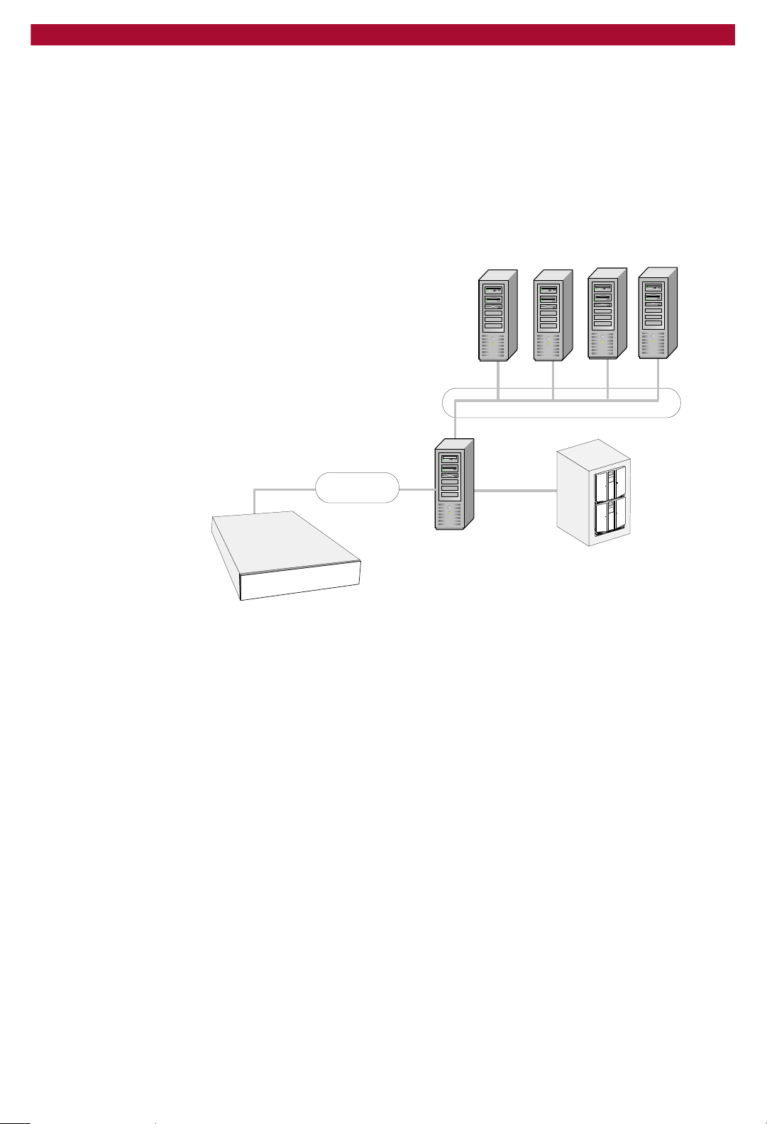
Disk-to-Disk-to-Tape (D2D2T) Backup Capabilities
The REO Appliance is a storage resource used by a single backup server
or shared by multiple backup servers using an Ethernet or FC network.
By using standard backup software, you can copy backup data that
resides on the REO Appliance to tape for long-term data retention.
The following illustration shows application servers sending backup data
over a 10/100 or Gigabit Ethernet (GbE) LAN to backup servers sharing
REO Appliance D2D storage over GbE or FC.
Application servers
Ethernet/FC
Backup Network, 10/100/1000 BaseT
Ethernet
Setup Guide
Storage-Area Network, GbE or FC
Ethernet/FC
Backup Server
Tape
REO
In addition to being part of the LAN, the backup servers, and the REO
Appliance are part of the GbE backup SAN.
Important Concepts to Understand W 13
Page 14
Overland Storage REO 9000 with ProtectionPAC Software
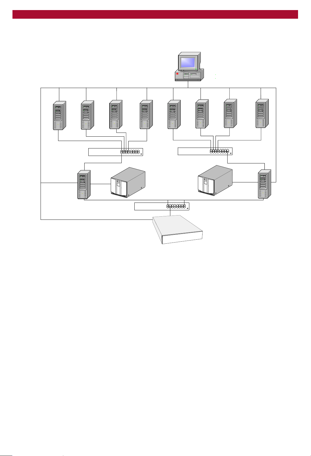
The following diagrams show two different ways of configuring a REO
Appliance with multiple backup servers.
LAN
Management
browser
interface (console)
GbE or 10/100
10/100
Management
Server 3Server 2Server 1
GbE or 10/100
GbE or 10/100
Backup server
SCSI
Server 4
GbE or 10/100
GbE or 10/100
Tape sub-system
GbE or FC Switch
GbE or 10/100
GbE or 10/100
REO
GbE or 10/100
Server 8Server 7Server 6Server 5
GbE or 10/100
Backup server
SCSI
Tape sub-system
14 X Reviewing REO 9000 Concepts and Requirements
Page 15
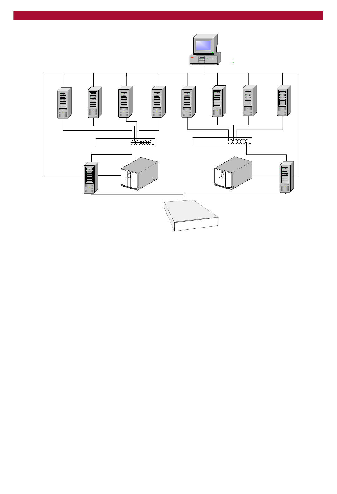
LAN
Management
browser
interface (console)
Setup Guide
Server 4
GbE or 10/100
GbE or 10/100
Tape sub-system
GbE or 10/100
GbE or 10/100
GbE or 10/100
GbE or 10/100
10/100
Management
Server 3Server 2Server 1
GbE or 10/100
GbE or 10/100
Backup server
SCSI
REO
Redundant Array of Independent Disks (RAID)
RAID provides convenient, low-cost, reliable storage by saving data on
more than one disk drive simultaneously. If one disk drive in a RAID 5
configuration becomes unavailable, the others continue to work in a
degraded state, thus avoiding downtime for users.
Server 8Server 7Server 6Server 5
GbE or 10/100
Backup server
SCSI
Tape sub-system
Note: Because RAID 5 is designed for data protection, you might see
performance degradation when compared to JBOD operations.
RAID allows you to group the individual disk drives on the REO
Appliance into logical disk drives of different sizes. You can configure
your REO Appliance to create two physical RAID volumes by selecting
either of the following RAID options:
RAID 0. This configuration uses striping, which provides enhanced
performance and volume-level capacity. It divides the data into blocks
and writes each block to a separate disk drive, which improves
performance by dispersing the input and output load. RAID 0 does not
provide data redundancy.
RAID 5. This configuration uses striping and distributed parity,
which provides a balance between performance and availability. In
addition to dividing the data into blocks as described for RAID 0, the
parity information is also striped across the disks. If one of the disk
drives fails, you can use the parity information to rebuild the lost data.
In addition to using either of the preceding RAID configurations, you can
also take advantage of logical volume management (LVM) and create
logical volumes from the data pool.
Important Concepts to Understand W 15
Page 16

Overland Storage REO 9000 with ProtectionPAC Software
If you use a RAID 5 configuration, you can also set aside a disk drive for
each physical host (controller); that is, you can create a hot spare. These
disk drives remain in standby mode, and you can use them immediately
if another disk fails.
Tape Emulation
The ProtectionPAC software includes two tape emulation features, which
you can use to create virtual linear tape-open (LTO-2) tape devices that
provide 2-to-1 compression ratios with typical data sets (actual
performance might vary with application). When you use tape emulation,
the disk drives on the REO Appliance appear to your backup software as
LTO-2 tape drives, which simplifies the setup process while
simultaneously providing data compression and the attributes of backing
up data to disk.
Depending on the configuration that you use, you get a different number
of virtual LTO-2 devices. In the just-a-bunch-of-disks (JBOD)
configuration, you can have up to 24. If you use RAID 0 or 5 without
logical volumes, you can have four. If you use logical volumes with
RAID 0 or 5, you can create up to 64 virtual LTO-2 devices.
If you decide to use tape emulation, you also have the option of using
fixed-length (Tape) or dynamic-length (Dynamic Tape) devices. To take
advantage of the Dynamic Tape option, you must use logical volumes,
which is described in the next section. Using Dynamic Tape lets you
create devices that adjust to the size of individual backup jobs.
Logical Volume Management (LVM)
With LVM, you can combine the two physical RAID volumes into
multiple logical volumes (partitions) of different sizes and assign logical
unit numbers (LUNs) to represent the different volumes, or REO devices.
This feature lets you set up and assign devices to different systems
according to your needs and the configuration and type of storage
network that you use.
Using this feature in the ProtectionPAC software, you can create up to 64
LUNs, and you can reassign space allocation for disk or standard (not
dynamic) virtual tape devices, in 1 gigabyte (GB) increments, on the fly.
Reviewing Pre-Installation Requirements
Before attempting to operate the REO Appliance with your backup
servers, verify that your network meets the minimum requirements
specified in the following sections.
Important: If you purchased multiple units, set up (attach and
configure) one unit at a time. The target names must be unique within
a network; that is, if you are using multiple appliances, you must
change the default target names.
Also, be aware that the keys are not interchangeable and Overland
strongly recommends that you make a backup copy of the files on the
keys before and after you configure them.
16 X Reviewing REO 9000 Concepts and Requirements
Page 17

Network
Setup Guide
For best results, Overland Storage strongly recommends that you use a
dedicated GbE network to share the storage resources on the REO
Appliance among multiple backup servers.
To ensure optimum performance, always use the appropriate patch
cables to connect the REO Appliance to the backup-server storage
network. To select the appropriate cables, use the following guidelines:
If you intend to use GbE, you must use Category 5E (or better) cables
for GbE connections. You can use either straight-through or cross-over
cables.
If you intend to connect the REO Appliance to a 100 BaseT network,
use CAT 5 (or better) shielded (screened) or unshielded 100-ohm
twisted-pair RJ-45 network cables. Also:
If you intend to connect the Management Port, which is a 10/100
port, to an application or backup server via a switch, you must use
a straight-through cable.
If you intend to connect the Management Port directly to your
application or backup server (without a switch), you must use a
cross-over cable.
The maximum length of cable for any Ethernet-based network
connection is 328 feet (100 meters).
Note: For smaller environments, you can attach the REO Appliance
directly to a single application or backup server by using standard
Category 5E cables without the use of a switch.
iSCSI Initiators
iSCSI initiators are required to communicate with the iSCSI targets
(REO Devices) on the REO Appliance. Each backup server that will
interface with the REO Appliance must be equipped with a software- or
hardware-based initiator. The REO Appliance supports any computing
platform with an available iSCSI initiator, either in software or using an
iSCSI HBA (it must be iSCSI draft 20/version 1.0).
Reviewing Pre-Installation Requirements W 17
Page 18

Overland Storage REO 9000 with ProtectionPAC Software
Setting the SCSI Time-Out Value in Windows Environments
If you intend to use your REO Appliance in a Windows environment, be
aware that there are certain operating conditions in which time-out
errors might occur. These errors usually result in the system reporting a
disk failure for the associated REO Appliance disk drive or drives. (These
errors might be reported as iSCSIPrt errors in the System Log of the
Event Viewer. Examples include an Event ID 9 [Target did not respond
in time for a SCSI request…] and Event ID 39 [Initiator sent a task
management command to reset the target…]. Other symptoms might
include “Lost Delayed Write Data” system error messages or similar
error messages related to the REO Appliance disk drives.)
The reason that these disk time-out errors can occur is because the
default I/O time-out value for Windows is 20 seconds, which is not
sufficient to support the default iSCSI protocol time-out value of 60
seconds. When you install and set up your REO Appliance, Overland
strongly recommends that you set this value to 60 seconds.
To set the time-out value to 60 seconds
1 On the Windows system, run regedit.
Warning: If you edit the registry incorrectly, you might cause serious
problems that require you to reinstall your operating system. Edit the
registry at your own risk. Prior to making any changes, refer to the
following Microsoft Knowledge Base article:
http://support.microsoft.com/default.aspx?scid=kb;en-us;322755
2 In HKEY_LOCAL_MACHINE\System\CurrentControlSet\
Services\Disk, edit or add the TimeOutValue entry to set it to 60
seconds in decimal format ((0000003c in hexadecimal).
To edit the value for the TimeOutValue entry if it already exists,
double-click the entry, enter the new value, and click OK.
To add the TimeOutValue entry if it does not yet exist, right-click
anywhere in the list of values, and then click New > DWORD value.
Name the new value TimeOutValue, and then double-click it to edit
the setting.
18 X Reviewing REO 9000 Concepts and Requirements
Page 19
2
CHAPTER
Setting Up the REO 9000
The main steps involved in setting up the REO Appliance include:
Step 1 Unpacking the REO Appliance, and reviewing safety guidelines.
Step 2 If you intend to position the REO Appliance in a rack, attaching the
required components.
Step 3 Connecting the REO Appliance to the management LAN.
Step 4 Connecting the REO Appliance to the application and backup servers,
SAN for the backup servers, or FC.
Step 5 Connecting external SCSI devices.
Step 6 Attaching the power cords.
Preparing the REO Appliance
Caution: Due to the weight of each rack-mounted unit when it is fully
extended, you should install units from the bottom up. Extending a
unit that has empty spaces beneath it might cause the rack to tip
forward or might cause personal injury. Overland Storage
recommends that two people support and slide the unit in the rack.
Vorsicht: Aufgrund des Gewichtes eines Gerätes, welches für den
Einbau in ein Rack gedacht ist, empfehlen wir Ihnen, dieses von unten
nach oben in das Rack zu installieren. Wenn Sie ein Gerät aus dem
Rack heraus ziehen, könnte es Ihnen entgleiten und so zu
Verletzungen führen. Wir empfehlen den Ein- und Ausbau des
Gerätes durch zwei Personen.
Setting Up the REO 9000 W 19
Page 20

Overland Storage REO 9000 with ProtectionPAC Software
1 Unpack the REO Appliance.
The shipping container contains the following:
Overland Storage appliance chassis
Depending on which version of the product that you purchased, either
12 or 24 disk carriers and disk drives
Power cords (U.S.) (Approved cord sets shall be used in countries
outside North America.)
Appliance face-plate
REO SoftKey
Rack-mount hardware
Documentation CD-ROM and poster
2 Review the following guidelines prior to positioning the REO Appliance
physically within your network.
Make sure that the REO Appliance is accessible.
Make sure there is unrestricted air flow around the unit and through
the vents in the sides and rear of the case.
Route external cables so that they can be connected easily without
blocking air vents or impeding air flow.
Protect the REO Appliance from extreme temperature and humidity.
Overland Storage recommends that you install the REO Appliance in
a clean, air-conditioned environment where water and moisture
cannot enter the case of the REO Appliance. Keep the air as free from
dust as possible.
Protect the REO Appliance from physical shock and vibration.
Make sure that the inlet air temperature within the rack remains
below the specified limit of 95°F (35°C).
Keep the REO Appliance and cabling away from sources of electrical
noise such as elevator shafts, stereo speakers, microwave ovens, air
conditioning units, and even telephones. Electromagnetic fields can
interfere with the signals on copper cabling and introduce errors,
therefore slowing down the network.
20 X Setting Up the REO 9000
Page 21
Positioning the REO Appliance in a Rack
Caution: Due to the weight of each rack-mounted unit when it is fully
extended, you should install units from the bottom up. Extending a
unit that has empty spaces beneath it might cause the rack to tip
forward or might cause personal injury. Overland Storage
recommends that two people support and slide the unit in the rack.
Vorsicht: Aufgrund des Gewichtes eines Gerätes, welches für den
Einbau in ein Rack gedacht ist, empfehlen wir Ihnen, dieses von unten
nach oben in das Rack zu installieren. Wenn Sie ein Gerät aus dem
Rack heraus ziehen, könnte es Ihnen entgleiten und so zu
Verletzungen führen. Wir empfehlen den Ein- und Ausbau des
Gerätes durch zwei Personen.
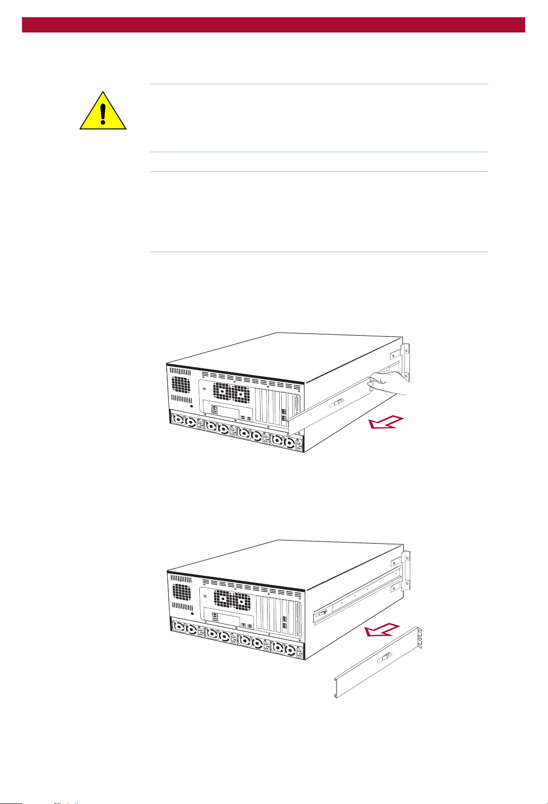
To install the unit in a rack
1 Separate each set of slides as follows:
Pull the outer slide toward the rear, along with the intermediate slide,
until the inner slide-lock engages the intermediate slide.
Setup Guide
REO90002
Continue to pull the outer slide towards the rear until the outer slide-
lock engages the intermediate slide. To permit the intermediate slide
to continue to move toward the rear, press the inner slide-lock button.
Continue to move the outer and intermediate slides toward the rear
until they are separated from the inner slide.
REO90005
Positioning the REO Appliance in a Rack W 21
Page 22
Overland Storage REO 9000 with ProtectionPAC Software
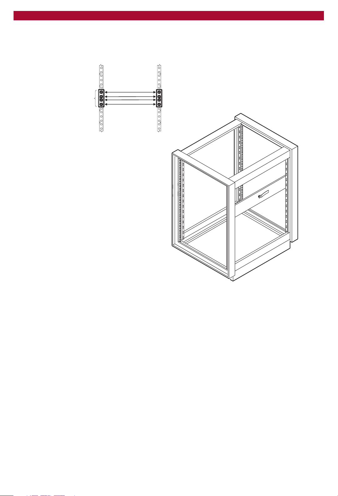
2 Locate the screw holes in the front and rear rails of the rack where the
REO Appliance slides will be installed.
The unit uses 5U of rack space.
Location of rails and
mounting hardware
Nut plates,
slide rails,
bar nuts, and
mounting screws
REO90007
REO90051
3 Fasten each outer slide by using 10-32 screws (with washers, if needed)
and one nut plate.
22 X Setting Up the REO 9000
Page 23
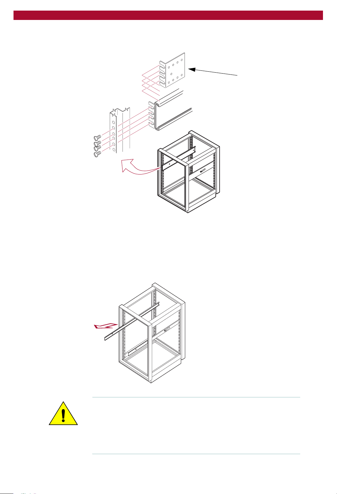
Setup Guide
Select slots in the mounting brackets so that the length of the assembly
equals the distance between the front and rear rails of the rack.
Nut Plate
REO90063
Note: When fastening the adjustable bracket, allow room for the slide to
pass by the inside of the rack.
4 Tighten all the screws.
5 If they are not already locked in the extended position, pull the
intermediate slides toward the front (out of the rack) so that they lock in
the extended position.
REO0065
Caution: The disk drives for the REO Appliance are located in the front
of the unit. The result being the majority of weight is distributed to the
front of the REO Appliance. This next step should be performed by at
least two people, or by using a mechanical lift. Make certain that when
the REO Appliance is fully extended that a force of 20% of the rack’s
weight, but not more than lb. (Kg), applied in any direction other than
upwards, does not cause the rack to overbalance.
Positioning the REO Appliance in a Rack W 23
Page 24
Overland Storage REO 9000 with ProtectionPAC Software
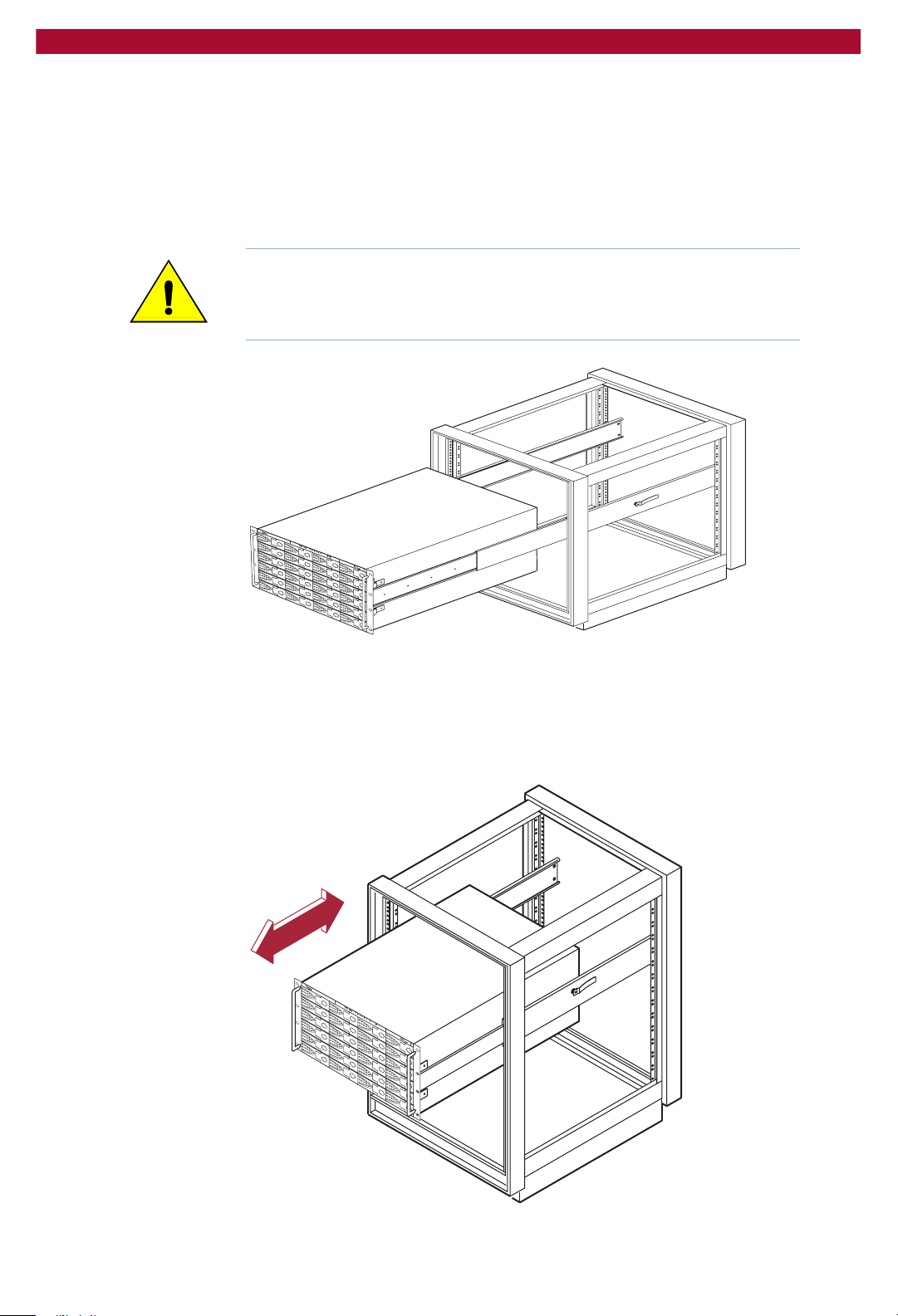
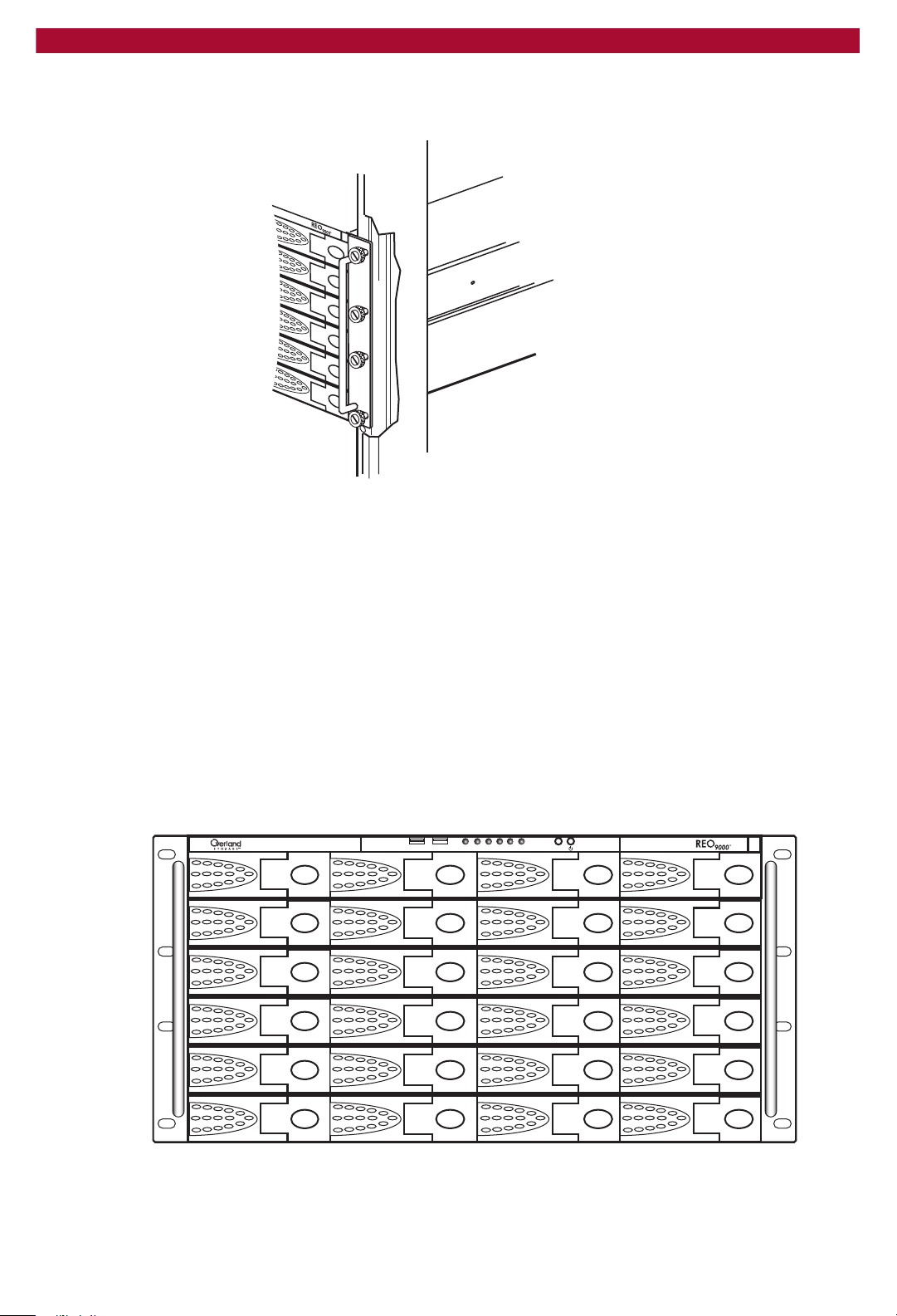
6 At the front of the rack, lift the REO Appliance to its installed height,
engage the inner slides mounted on the REO Appliance with the
intermediate slides protruding from the rack, and slide the REO
Appliance toward the rack until the inner slide-lock engages the
intermediate slide.
This leaves the entire REO Appliance protruding from the rack, locked in
position, supported by the slide rails.
Caution: With one unit installed in the rack and in the extended
position, support might be required (to prevent the rack from tipping)
until the unit is pushed completely into the rack. (The unit is shown in
the middle of the rack for clarity.)
REO90003
7 Press inward (toward the chassis) on each of the inner slide-locks to
permit the intermediate slides to move toward the rack.
8 Slide the
inner and outer slide locks engage, and that the
REO Appliance in and out several times, ensuring that the
REO Appliance chassis
does not bind against the slides.
24 X Setting Up the REO 9000
REO90001
Page 25
Setup Guide
9 Slide the REO Appliance into the rack, and attach the captive screw on
each panel extension (left and right sides) to the rack and nut plate.
REO90006
Installing the Disk Carriers and Disk Drives
The disk carriers, which contain the disk drives, are packaged
separately, which allows you to insert them into the chassis after you
have installed the chassis in the rack.
1 Remove the package of desiccant from each slot in the chassis.
2 Insert the first disk carrier in to the applicable slot in the chassis.
3 Close the disk carrier by doing the following:
a Make sure that the lever is in its fully extended, open position.
b Press the right side of the carrier into the slot.
c Press the lever in. Pressing the lever in draws the carrier fully into the
slot and locks it in place.
01 23
4567
8 9 10 11
12
13
14
15
16 17 18 19
4 Repeat these steps for each disk carrier.
5 Attach the appliance face-plate.
Installing the Disk Carriers and Disk Drives W 25
23222120
Page 26
Overland Storage REO 9000 with ProtectionPAC Software
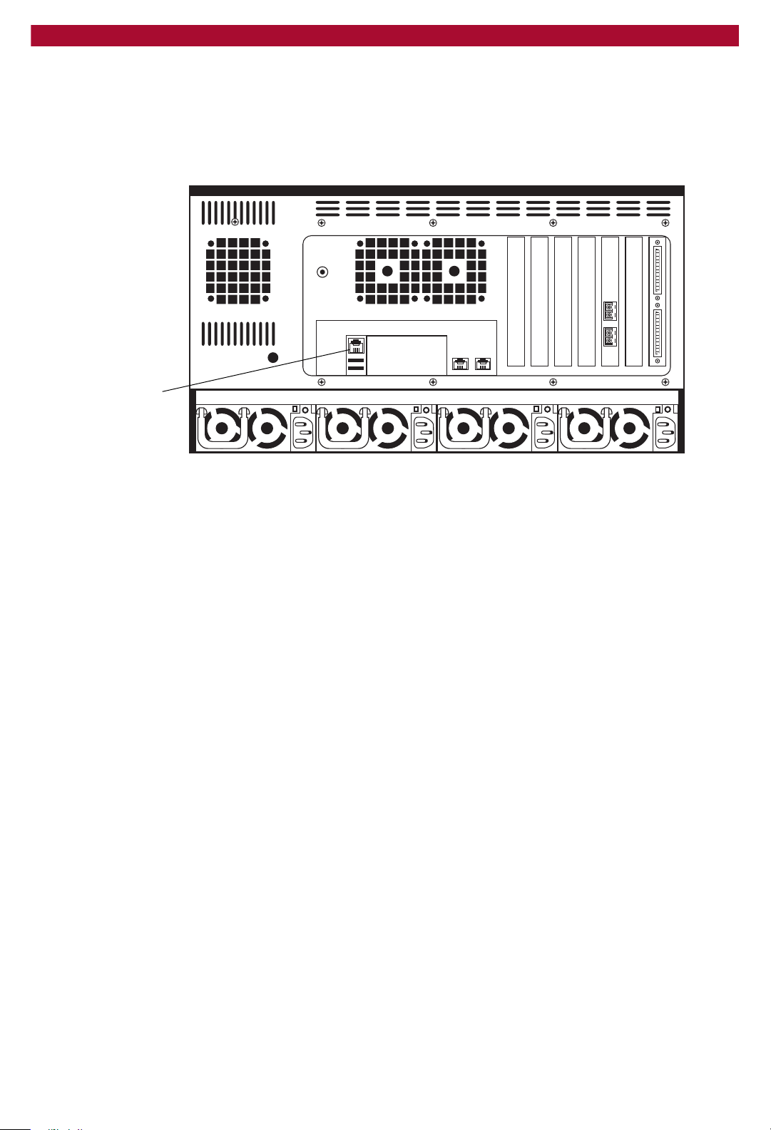
Connecting the REO Appliance to the Management LAN
X Using the Management Port (10/100), connect the REO Appliance to
your LAN via the twisted-pair network cables.
Management
Port
26 X Setting Up the REO 9000
Page 27
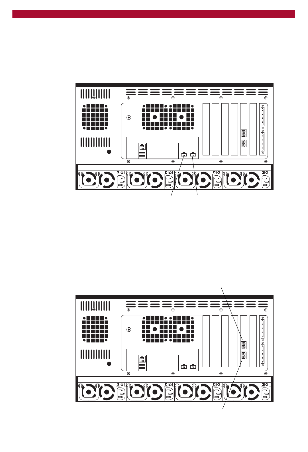
Connecting the REO Appliance to the Network
Use the following instructions to connect your REO Appliance to your
backup servers, SAN, or FC switch.
1 For iSCSI connectivity, use Data Port 1 to connect the REO Appliance
to a backup server via the twisted-pair network cables.
Setup Guide
Data Port 2 Data Port 1
2 For additional iSCSI connectivity, use Data Port 2 to connect the REO
Appliance to a second backup server via the twisted-pair network cables.
You can connect backup servers to the REO Appliance by using a directconnect cable or by using a GbE switch.
3 If you are using FC, connect the Fibre Channel Ports on the rear of the
REO Appliance to your FC switch or hub.
The Fibre Channel ports on the back of the REO Appliance are numbered
port 0 (bottom) and port 1 (top).
Port 1
Port 0
Connecting the REO Appliance to the Network W 27
Page 28
Overland Storage REO 9000 with ProtectionPAC Software
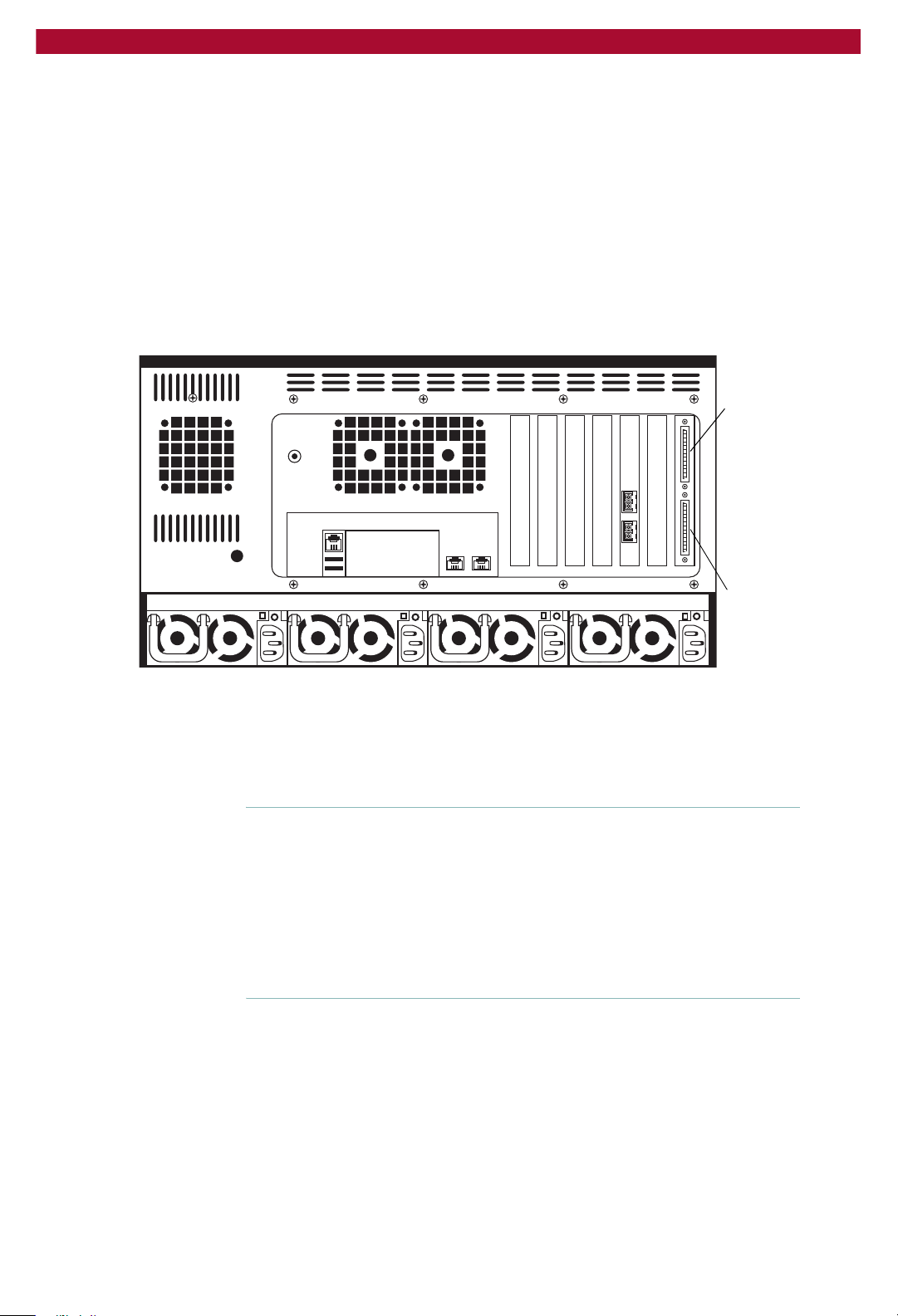
Connecting External Devices to the REO Appliance
The REO Appliance includes two Ultra320 SCSI ports, which support
SCSI devices such as medium changers and tape drives. You can use a
chain formation to assign up to 15 SCSI IDs to each port.
To connect SCSI devices to your REO Appliance
X On the rear of the REO Appliance, attach the applicable devices to the
SCSI ports.
You must use an external 68-pin SCSI cable that includes a male connect
with thumbscrews to connect a device to the port. (This cable is not
included with the REO Appliance.)
SCSI port 0
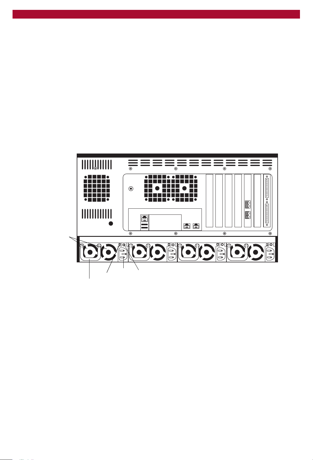
Attaching the Power Cords
1 Attach all four power cords to the REO Appliance.
2 Plug the power cords in to an AC power source (do not turn the power on).
Important: You must connect and use all four power cords; if one of the
cords is disconnected or malfunctioning, the REO Appliance beeps
repeatedly until the situation is resolved. Overland Storage
recommends that you use separate power mains for the power sources.
If you are not using Dynamic Host Configuration Protocol (DHCP), it
is critical to the configuration process that you refrain from enabling
power to the REO Appliance before completing the configuration steps
specified in the next chapter.
Power problems can be the cause of serious failures and downtime in
your network. Ensure that the power input to your system is clean and
free from sags and surges to avoid unforeseen network outages. Overland
Storage strongly recommends that you install power conditioning and an
adequately rated uninterruptible power supply (UPS), especially in areas
prone to blackouts, power dips, and electrical storms.
The REO Appliance is intended to be grounded. Ensure it is connected to
earth ground during normal use. Installing proper grounding helps to
avoid damage from lightning and power surges.
SCSI port 1
28 X Setting Up the REO 9000
Page 29
Setup Guide
Each power supply contains:
A socket for insertion of an AC line cord.
A two-color LED for indicating the status of the power supply. When
AC is applied to the supply and standby voltages are available, the
LED becomes red. When all outputs are available, the LED becomes
green. If the power supply fails, the LED becomes red.
A latch for releasing the power supply from the REO Appliance.
A handle for pulling the power supply out of the REO Appliance.
A pair of fans for preventing the power supply from overheating.
A feature that verifies the following (if not detected, an alarm signal
sounds):
All output voltages V1 to V5 are within regulation.
The fans are operating normally.
The internal temperature of the power supply is normal.
Fans
Extraction handle
3 Complete the steps outlined in the next chapter, Using the REO SoftKey
Release latch
Socket
Thumbscrew
to Start the REO 9000 on page 31.
Attaching the Power Cords W 29
Page 30

Overland Storage REO 9000 with ProtectionPAC Software
30 X Setting Up the REO 9000
Page 31

3
Using the REO SoftKey to Start
CHAPTER
the REO 9000
The main steps involved in using the key to start the REO Appliance
include:
Step 1 Making a backup copy of the key.
Step 2 If your network does not use DHCP, manually editing the configuration
and network files on the key.
Step 3 Connecting the key to the REO Appliance.
Understanding What the REO SoftKey Is
The REO SoftKey is a removable USB disk drive on a key ring. It
contains the software and settings required for configuring the REO
Appliance and must be inserted in the REO Appliance whenever you
restart it (because the REO Appliance uses a Linux-based OS, the key is
formatted using the virtual file allocation table [VFAT]). You can also use
the REO SoftKey to download and install updates when they become
available.
Important: If you purchased multiple units, note that the keys are not
interchangeable
The simplest configuration can be achieved when your LAN uses
DHCP on its own subnetwork (subnet). If your LAN does not use
DHCP, you must manually edit the configuration file located on the
REO SoftKey before continuing.
Using the REO SoftKey to Start the REO 9000 W 31
Page 32

Overland Storage REO 9000 with ProtectionPAC Software
Backing Up Your REO SoftKey (Pre-Configuration)
Make a backup copy of all the files on the REO SoftKey before and after
you configure it.
1 Remove the cap from the REO SoftKey, and insert it into a USB port on
a Windows 2000, 2003, or XP system that contains active virusprotection software.
Note: If you have not previously installed a USB mass-storage device,
Windows displays a dialog box that indicates it has found new
hardware and will automatically install the necessary drivers on your
system.
2 Double-click My Computer on your desktop (or use Windows Explorer),
and browse to the software-key disk drive.
The name of this disk drive varies based on your system configuration,
but it will be called something like Removable Disk (G:).
Make a backup copy of all the folders and files contained on the REO SoftKey.
3 Make a backup copy of all the data on the REO SoftKey, and store the
copy in a secure location.
4 To determine your next step, choose one of the following:
If your LAN uses DHCP, continue from step 1 under Connecting the
REO SoftKey to the REO Appliance on page 36.
If your LAN does not use DHCP, complete the steps outlined in the
next section, Editing the Configuration File (for a non-DHCP or UNIX
Management System), before continuing.
32 X Using the REO SoftKey to Start the REO 9000
Page 33

Editing the Configuration File (for a non-DHCP or UNIX Management System)
1 With the key still inserted into a USB port on a Windows 2000, 2003, or
XP system that contains active virus-protection software, browse to the
software-key disk drive.
2 Open the ipkey folder, and locate the ifcfg-eth0 file.
The ifcfg-eth0 is the configuration file for the Management Port on the
REO Appliance.
Setup Guide
Open the ipkey folder, right-click ifcfg-eth0, and click Properties.
3 Right-click the ifcfg-eth0 file, and click Properties.
4 On the General tab, if the Read-only check box is selected, clear it, and
then click OK; otherwise, click Cancel.
5 Right-click the ifcfg-eth0 file again, click Open With, and then select
WordPad (or a comparable text editor).
Tip: Overland Storage recommends that you use WordPad, because it
displays the configuration information in an easy-to-use format.
Editing the Configuration File (for a non-DHCP or UNIX Management System) W 33
Page 34

Overland Storage REO 9000 with ProtectionPAC Software
6 Make the following changes:
Change the BOOTPROTO field from dhcp to static (make sure that
you enter it in lowercase).
After the BOOTPROTO line, enter lines for IPADDR, NETMASK,
NETWORK, and BROADCAST, and, in each corresponding field,
enter the IP address you selected for the management interface for the
REO Appliance on your network.
Note: You do not need to modify the other fields at this time.
7 Save the file; when asked if you want to replace the existing file, click
Yes.
8 In the ipkey folder, locate the network file.
Locate and open the network file.
9 Right-click the network file, click Open With, and then select
WordPad.
Change GATEWAY to the
applicable IP address.
34 X Using the REO SoftKey to Start the REO 9000
Page 35

Setup Guide
10 Change the contents of the GATEWAY field to the applicable IP address,
and save and exit the file.
Note: If you are using a direct connection (private network), leave the
GATEWAY address as 0.0.0.0.
11 Remove the REO SoftKey from the system by doing the following:
a Double-click the Unplug or Eject Hardware icon, located in the
system tray (lower-right corner of the task bar).
b In the Unplug or Eject Hardware dialog box, select the device you
want to unplug (the key is identified as USB Mass Storage Device),
and click Stop.
Select USB Mass Storage Device,
and then click Stop.
c In the Stop a Hardware device dialog box, select USB Mass
Storage Device, and then click OK.
Select USB Mass Storage Device
again, and then click OK.
d When the message appears that indicates it is safe to remove the
device, click OK, and remove the REO SoftKey.
12 Complete the steps outlined in the next section, Connecting the REO
SoftKey to the REO Appliance.
Editing the Configuration File (for a non-DHCP or UNIX Management System) W 35
Page 36

Overland Storage REO 9000 with ProtectionPAC Software
Connecting the REO SoftKey to the REO Appliance
1 Insert the REO SoftKey into the USB port located on the back of the REO
Appliance.
Insert the key.
2 To turn the REO Appliance on, press and hold the power button for
approximately 1 second.
Important: If you purchased multiple units, enable power to only one
unit at this point; you must set up one unit at a time.
36 X Using the REO SoftKey to Start the REO 9000
Page 37

Setup Guide
The power button is located on the front of the appliance. The power
button is a momentary contact device that needs to be pressed and held
for about 1 second to begin the power-up sequence.
Press and hold the power button for 1 second.
After you turn the power on, the REO Appliance performs a self-test
process and loads the necessary information from the REO SoftKey.
Following successful completion of the self-test, which takes several
minutes, you should hear 3 beep tones.
3 Listen for the series of 3 beep tones spaced about 1 second apart.
Important: On startup, the REO Appliance might reach an error state
and begin an endless loop of alerts. The pattern (2 beeps separated by
a 1-second delay) repeats every 4 seconds. If this occurs, turn the
appliance off and then back on. For more information, see Perpetual
Loop of Audio Alerts on page 127.
4 After you hear the beep tones, proceed to the configuration steps outlined
in the next chapter, Configuring the Management System on page 39.
If you are unable to hear the tones in your physical environment, wait
approximately five minutes before continuing.
Note: You must leave the REO Appliance on and the REO SoftKey
inserted while completing the configuration process for your
application and backup servers.
Connecting the REO SoftKey to the REO Appliance W 37
Page 38

Overland Storage REO 9000 with ProtectionPAC Software
38 X Using the REO SoftKey to Start the REO 9000
Page 39

4
Configuring the Management
CHAPTER
System
The main steps involved in configuring the management system include:
Step 1 Establishing communication with the REO Appliance by mapping it to a
drive letter (Windows only).
Step 2 Verifying that the gateway and Management Port information are
correct.
Step 3 Entering the GbE Data Port, Fibre Channel, and system information.
Step 4 Setting up your logon information.
Step 5 Configuring e-mail alerts.
Step 6 Setting the applicable time zone information.
The images shown in the following sections might appear slightly
different if you are using a different browser or a UNIX-based system.
Mapping a Network Drive to the REO Appliance (Windows Only)
To access the components used for installation and configuration of the
REO Appliance, you must map a network drive from the REO Appliance
to the system that will operate the REO Appliance console.
1 Make sure that REO SoftKey is still inserted in a USB port on the REO
Appliance.
2 Right-click My Computer on your desktop, and click Map Network
Drive.
Configuring the Management System W 39
Page 40

Overland Storage REO 9000 with ProtectionPAC Software
3 Use the default network drive displayed or select another drive from the
list.
Tip: For consistency, Overland Storage recommends that you select a
drive letter, such as drive Z, that is available to all systems on the
backup network.
4 In the Folder box of the Map Network Drive dialog box, type
\\REO\programs, and make sure that the Reconnect at login box is
cleared.
Note: Because the folder might not be visible if you use the Browse
button, Overland Storage recommends that you type
directly in the Folder text box.
\\REO\programs
5 Click Finish.
6 If prompted for your name and password, enter the following in case-
sensitive format:
Logon Name: Administrator
Password: system
40 X Configuring the Management System
Page 41

Tracking Configuration Information
As you complete the configuration process by following the steps outlined
in this and subsequent chapters, use the following forms to note what
information you enter.
Important: This information will be useful if you have to reconfigure the
REO Appliance for any reason, such as a lost or damaged REO
SoftKey.
Network Configuration Page
Setup Guide
Default Gateway
IP Address:
Management Port
IP Address:
Subnet Mask:
Network Address:
Broadcast Address:
DHCP:
Data Port 1
IP Address:
Subnet Mask:
Network Address:
Broadcast Address:
System Information
Workgroup/Domain Name:
REO Description:
REO Name:
Data Port 2
Network Address:
Broadcast Address:
Fibre Channel Configuration
WWPN(0)
WWPN(1)
System Configuration Page
E-mail Notification
Address for Critical:
IP Address:
Subnet Mask:
Link Speed:
Link Topology:
Link Speed:
Link Topology:
Mail Address:
From Address:
Address for All:
Alert Frequency:
Tracking Configuration Information W 41
Page 42

Overland Storage REO 9000 with ProtectionPAC Software
REO Device ID 0
Device Type:
ShareDevice:
Tape Compression:
Disk, Tape, Dyn. Tape
Yes or No
Yes or No
Dyn. Tape Max. Size:
iSCSI Target Name:
REO Device ID 1
Device Type:
ShareDevice:
Tape Compression:
Disk, Tape, Dyn. Tape
Yes or No
Yes or No
Dyn. Tape Max. Size:
iSCSI Target Name:
REO Device ID 2
Device Type:
ShareDevice:
Tape Compression:
Disk, Tape, Dyn. Tape
Yes or No
Yes or No
Dyn. Tape Max. Size:
iSCSI Target Name:
REO Device ID 3
Device Type:
ShareDevice:
Tape Compression:
Disk, Tape, Dyn. Tape
Yes or No
Yes or No
Dyn. Tape Max. Size:
iSCSI Target Name:
REO Device ID 4
Device Type:
ShareDevice:
Tape Compression:
Disk, Tape, Dyn. Tape
Yes or No
Yes or No
Dyn. Tape Max. Size:
iSCSI Target Name:
REO Device ID 5
Device Type:
ShareDevice:
Tape Compression:
Disk, Tape, Dyn. Tape
Yes or No
Yes or No
Dyn. Tape Max. Size:
iSCSI Target Name:
REO Device ID 6
Device Type:
ShareDevice:
Tape Compression:
Disk, Tape, Dyn. Tape
Yes or No
Yes or No
Dyn. Tape Max. Size:
iSCSI Target Name:
REO Device ID 7
Device Type:
ShareDevice:
Tape Compression:
Disk, Tape, Dyn. Tape
Yes or No
Yes or No
Dyn. Tape Max. Size:
iSCSI Target Name:
REO Device Configuration Page
Connection Type:
iSCSI Initiator Name:
Initiator IP Address:
Connection Type:
iSCSI Initiator Name:
Initiator IP Address:
Connection Type:
iSCSI Initiator Name:
Initiator IP Address:
Connection Type:
iSCSI Initiator Name:
Initiator IP Address:
Connection Type:
iSCSI Initiator Name:
Initiator IP Address:
Connection Type:
iSCSI Initiator Name:
Initiator IP Address:
Connection Type:
iSCSI Initiator Name:
Initiator IP Address:
Connection Type:
iSCSI Initiator Name:
Initiator IP Address:
iSCSI or FC
iSCSI or FC
iSCSI or FC
iSCSI or FC
iSCSI or FC
iSCSI or FC
iSCSI or FC
iSCSI or FC
42 X Configuring the Management System
Page 43

REO Device ID 8
Device Type:
ShareDevice:
Tape Compression:
Dyn. Tape Max. Size:
iSCSI Target Name:
REO Device ID 9
Device Type:
ShareDevice:
Tape Compression:
Dyn. Tape Max. Size:
iSCSI Target Name:
REO Device ID 10
Device Type:
ShareDevice:
Tape Compression:
Dyn. Tape Max. Size:
iSCSI Target Name:
REO Device ID 11
Device Type:
ShareDevice:
Tape Compression:
Dyn. Tape Max. Size:
iSCSI Target Name:
REO Device ID 12
Device Type:
ShareDevice:
Tape Compression:
Dyn. Tape Max. Size:
iSCSI Target Name:
REO Device ID 13
Device Type:
ShareDevice:
Tape Compression:
Dyn. Tape Max. Size:
iSCSI Target Name:
REO Device ID 14
Device Type:
ShareDevice:
Tape Compression:
Dyn. Tape Max. Size:
iSCSI Target Name:
REO Device ID 15
Device Type:
ShareDevice:
Tape Compression:
Dyn. Tape Max. Size:
iSCSI Target Name:
REO Device Configuration Page (continued)
Disk, Tape, Dyn. Tape
Yes or No
Yes or No
Disk, Tape, Dyn. Tape
Yes or No
Yes or No
Disk, Tape, Dyn. Tape
Yes or No
Yes or No
Disk, Tape, Dyn. Tape
Yes or No
Yes or No
Disk, Tape, Dyn. Tape
Yes or No
Yes or No
Disk, Tape, Dyn. Tape
Yes or No
Yes or No
Disk, Tape, Dyn. Tape
Yes or No
Yes or No
Disk, Tape, Dyn. Tape
Yes or No
Yes or No
Connection Type:
iSCSI Initiator Name:
Initiator IP Address:
Connection Type:
iSCSI Initiator Name:
Initiator IP Address:
Connection Type:
iSCSI Initiator Name:
Initiator IP Address:
Connection Type:
iSCSI Initiator Name:
Initiator IP Address:
Connection Type:
iSCSI Initiator Name:
Initiator IP Address:
Connection Type:
iSCSI Initiator Name:
Initiator IP Address:
Connection Type:
iSCSI Initiator Name:
Initiator IP Address:
Connection Type:
iSCSI Initiator Name:
Initiator IP Address:
Setup Guide
iSCSI or FC
iSCSI or FC
iSCSI or FC
iSCSI or FC
iSCSI or FC
iSCSI or FC
iSCSI or FC
iSCSI or FC
Tracking Configuration Information W 43
Page 44

Overland Storage REO 9000 with ProtectionPAC Software
REO Device Configuration Page (continued)
REO Device ID 16
Device Type:
ShareDevice:
Tape Compression:
Disk, Tape, Dyn. Tape
Yes or No
Yes or No
Dyn. Tape Max. Size:
iSCSI Target Name:
REO Device ID 17
Device Type:
ShareDevice:
Tape Compression:
Disk, Tape, Dyn. Tape
Yes or No
Yes or No
Dyn. Tape Max. Size:
iSCSI Target Name:
REO Device ID 18
Device Type:
ShareDevice:
Tape Compression:
Disk, Tape, Dyn. Tape
Yes or No
Yes or No
Dyn. Tape Max. Size:
iSCSI Target Name:
REO Device ID 19
Device Type:
ShareDevice:
Tape Compression:
Disk, Tape, Dyn. Tape
Yes or No
Yes or No
Dyn. Tape Max. Size:
iSCSI Target Name:
REO Device ID 20
Device Type:
ShareDevice:
Tape Compression:
Disk, Tape, Dyn. Tape
Yes or No
Yes or No
Dyn. Tape Max. Size:
iSCSI Target Name:
REO Device ID 21
Device Type:
ShareDevice:
Tape Compression:
Disk, Tape, Dyn. Tape
Yes or No
Yes or No
Dyn. Tape Max. Size:
iSCSI Target Name:
REO Device ID 22
Device Type:
ShareDevice:
Tape Compression:
Disk, Tape, Dyn. Tape
Yes or No
Yes or No
Dyn. Tape Max. Size:
iSCSI Target Name:
REO Device ID 23
Device Type:
ShareDevice:
Tape Compression:
Disk, Tape, Dyn. Tape
Yes or No
Yes or No
Dyn. Tape Max. Size:
iSCSI Target Name:
Connection Type:
iSCSI Initiator Name:
Initiator IP Address:
Connection Type:
iSCSI Initiator Name:
Initiator IP Address:
Connection Type:
iSCSI Initiator Name:
Initiator IP Address:
Connection Type:
iSCSI Initiator Name:
Initiator IP Address:
Connection Type:
iSCSI Initiator Name:
Initiator IP Address:
Connection Type:
iSCSI Initiator Name:
Initiator IP Address:
Connection Type:
iSCSI Initiator Name:
Initiator IP Address:
Connection Type:
iSCSI Initiator Name:
Initiator IP Address:
iSCSI or FC
iSCSI or FC
iSCSI or FC
iSCSI or FC
iSCSI or FC
iSCSI or FC
iSCSI or FC
iSCSI or FC
44 X Configuring the Management System
Page 45

REO Device ID 24
Device Type:
ShareDevice:
Tape Compression:
Dyn. Tape Max. Size:
iSCSI Target Name:
REO Device ID 25
Device Type:
ShareDevice:
Tape Compression:
Dyn. Tape Max. Size:
iSCSI Target Name:
REO Device ID 26
Device Type:
ShareDevice:
Tape Compression:
Dyn. Tape Max. Size:
iSCSI Target Name:
REO Device ID 27
Device Type:
ShareDevice:
Tape Compression:
Dyn. Tape Max. Size:
iSCSI Target Name:
REO Device ID 28
Device Type:
ShareDevice:
Tape Compression:
Dyn. Tape Max. Size:
iSCSI Target Name:
REO Device ID 29
Device Type:
ShareDevice:
Tape Compression:
Dyn. Tape Max. Size:
iSCSI Target Name:
REO Device ID 30
Device Type:
ShareDevice:
Tape Compression:
Dyn. Tape Max. Size:
iSCSI Target Name:
REO Device ID 31
Device Type:
ShareDevice:
Tape Compression:
Dyn. Tape Max. Size:
iSCSI Target Name:
REO Device Configuration Page (continued)
Disk, Tape, Dyn. Tape
Yes or No
Yes or No
Disk, Tape, Dyn. Tape
Yes or No
Yes or No
Disk, Tape, Dyn. Tape
Yes or No
Yes or No
Disk, Tape, Dyn. Tape
Yes or No
Yes or No
Disk, Tape, Dyn. Tape
Yes or No
Yes or No
Disk, Tape, Dyn. Tape
Yes or No
Yes or No
Disk, Tape, Dyn. Tape
Yes or No
Yes or No
Disk, Tape, Dyn. Tape
Yes or No
Yes or No
Connection Type:
iSCSI Initiator Name:
Initiator IP Address:
Connection Type:
iSCSI Initiator Name:
Initiator IP Address:
Connection Type:
iSCSI Initiator Name:
Initiator IP Address:
Connection Type:
iSCSI Initiator Name:
Initiator IP Address:
Connection Type:
iSCSI Initiator Name:
Initiator IP Address:
Connection Type:
iSCSI Initiator Name:
Initiator IP Address:
Connection Type:
iSCSI Initiator Name:
Initiator IP Address:
Connection Type:
iSCSI Initiator Name:
Initiator IP Address:
Setup Guide
iSCSI or FC
iSCSI or FC
iSCSI or FC
iSCSI or FC
iSCSI or FC
iSCSI or FC
iSCSI or FC
iSCSI or FC
Tracking Configuration Information W 45
Page 46

Overland Storage REO 9000 with ProtectionPAC Software
REO Device Configuration Page (continued)
REO Device ID 32
Device Type:
ShareDevice:
Tape Compression:
Disk, Tape, Dyn. Tape
Yes or No
Yes or No
Dyn. Tape Max. Size:
iSCSI Target Name:
REO Device ID 33
Device Type:
ShareDevice:
Tape Compression:
Disk, Tape, Dyn. Tape
Yes or No
Yes or No
Dyn. Tape Max. Size:
iSCSI Target Name:
REO Device ID 34
Device Type:
ShareDevice:
Tape Compression:
Disk, Tape, Dyn. Tape
Yes or No
Yes or No
Dyn. Tape Max. Size:
iSCSI Target Name:
REO Device ID 35
Device Type:
ShareDevice:
Tape Compression:
Disk, Tape, Dyn. Tape
Yes or No
Yes or No
Dyn. Tape Max. Size:
iSCSI Target Name:
REO Device ID 36
Device Type:
ShareDevice:
Tape Compression:
Disk, Tape, Dyn. Tape
Yes or No
Yes or No
Dyn. Tape Max. Size:
iSCSI Target Name:
REO Device ID 37
Device Type:
ShareDevice:
Tape Compression:
Disk, Tape, Dyn. Tape
Yes or No
Yes or No
Dyn. Tape Max. Size:
iSCSI Target Name:
REO Device ID 38
Device Type:
ShareDevice:
Tape Compression:
Disk, Tape, Dyn. Tape
Yes or No
Yes or No
Dyn. Tape Max. Size:
iSCSI Target Name:
REO Device ID 39
Device Type:
ShareDevice:
Tape Compression:
Disk, Tape, Dyn. Tape
Yes or No
Yes or No
Dyn. Tape Max. Size:
iSCSI Target Name:
Connection Type:
iSCSI Initiator Name:
Initiator IP Address:
Connection Type:
iSCSI Initiator Name:
Initiator IP Address:
Connection Type:
iSCSI Initiator Name:
Initiator IP Address:
Connection Type:
iSCSI Initiator Name:
Initiator IP Address:
Connection Type:
iSCSI Initiator Name:
Initiator IP Address:
Connection Type:
iSCSI Initiator Name:
Initiator IP Address:
Connection Type:
iSCSI Initiator Name:
Initiator IP Address:
Connection Type:
iSCSI Initiator Name:
Initiator IP Address:
iSCSI or FC
iSCSI or FC
iSCSI or FC
iSCSI or FC
iSCSI or FC
iSCSI or FC
iSCSI or FC
iSCSI or FC
46 X Configuring the Management System
Page 47

REO Device ID 40
Device Type:
ShareDevice:
Tape Compression:
Dyn. Tape Max. Size:
iSCSI Target Name:
REO Device ID 41
Device Type:
ShareDevice:
Tape Compression:
Dyn. Tape Max. Size:
iSCSI Target Name:
REO Device ID 42
Device Type:
ShareDevice:
Tape Compression:
Dyn. Tape Max. Size:
iSCSI Target Name:
REO Device ID 43
Device Type:
ShareDevice:
Tape Compression:
Dyn. Tape Max. Size:
iSCSI Target Name:
REO Device ID 44
Device Type:
ShareDevice:
Tape Compression:
Dyn. Tape Max. Size:
iSCSI Target Name:
REO Device ID 45
Device Type:
ShareDevice:
Tape Compression:
Dyn. Tape Max. Size:
iSCSI Target Name:
REO Device ID 46
Device Type:
ShareDevice:
Tape Compression:
Dyn. Tape Max. Size:
iSCSI Target Name:
REO Device ID 47
Device Type:
ShareDevice:
Tape Compression:
Dyn. Tape Max. Size:
iSCSI Target Name:
REO Device Configuration Page (continued)
Disk, Tape, Dyn. Tape
Yes or No
Yes or No
Disk, Tape, Dyn. Tape
Yes or No
Yes or No
Disk, Tape, Dyn. Tape
Yes or No
Yes or No
Disk, Tape, Dyn. Tape
Yes or No
Yes or No
Disk, Tape, Dyn. Tape
Yes or No
Yes or No
Disk, Tape, Dyn. Tape
Yes or No
Yes or No
Disk, Tape, Dyn. Tape
Yes or No
Yes or No
Disk, Tape, Dyn. Tape
Yes or No
Yes or No
Connection Type:
iSCSI Initiator Name:
Initiator IP Address:
Connection Type:
iSCSI Initiator Name:
Initiator IP Address:
Connection Type:
iSCSI Initiator Name:
Initiator IP Address:
Connection Type:
iSCSI Initiator Name:
Initiator IP Address:
Connection Type:
iSCSI Initiator Name:
Initiator IP Address:
Connection Type:
iSCSI Initiator Name:
Initiator IP Address:
Connection Type:
iSCSI Initiator Name:
Initiator IP Address:
Connection Type:
iSCSI Initiator Name:
Initiator IP Address:
Setup Guide
iSCSI or FC
iSCSI or FC
iSCSI or FC
iSCSI or FC
iSCSI or FC
iSCSI or FC
iSCSI or FC
iSCSI or FC
Tracking Configuration Information W 47
Page 48

Overland Storage REO 9000 with ProtectionPAC Software
REO Device Configuration Page (continued)
REO Device ID 48
Device Type:
ShareDevice:
Tape Compression:
Disk, Tape, Dyn. Tape
Yes or No
Yes or No
Dyn. Tape Max. Size:
iSCSI Target Name:
REO Device ID 49
Device Type:
ShareDevice:
Tape Compression:
Disk, Tape, Dyn. Tape
Yes or No
Yes or No
Dyn. Tape Max. Size:
iSCSI Target Name:
REO Device ID 50
Device Type:
ShareDevice:
Tape Compression:
Disk, Tape, Dyn. Tape
Yes or No
Yes or No
Dyn. Tape Max. Size:
iSCSI Target Name:
REO Device ID 51
Device Type:
ShareDevice:
Tape Compression:
Disk, Tape, Dyn. Tape
Yes or No
Yes or No
Dyn. Tape Max. Size:
iSCSI Target Name:
REO Device ID 52
Device Type:
ShareDevice:
Tape Compression:
Disk, Tape, Dyn. Tape
Yes or No
Yes or No
Dyn. Tape Max. Size:
iSCSI Target Name:
REO Device ID 53
Device Type:
ShareDevice:
Tape Compression:
Disk, Tape, Dyn. Tape
Yes or No
Yes or No
Dyn. Tape Max. Size:
iSCSI Target Name:
REO Device ID 54
Device Type:
ShareDevice:
Tape Compression:
Disk, Tape, Dyn. Tape
Yes or No
Yes or No
Dyn. Tape Max. Size:
iSCSI Target Name:
REO Device ID 55
Device Type:
ShareDevice:
Tape Compression:
Disk, Tape, Dyn. Tape
Yes or No
Yes or No
Dyn. Tape Max. Size:
iSCSI Target Name:
Connection Type:
iSCSI Initiator Name:
Initiator IP Address:
Connection Type:
iSCSI Initiator Name:
Initiator IP Address:
Connection Type:
iSCSI Initiator Name:
Initiator IP Address:
Connection Type:
iSCSI Initiator Name:
Initiator IP Address:
Connection Type:
iSCSI Initiator Name:
Initiator IP Address:
Connection Type:
iSCSI Initiator Name:
Initiator IP Address:
Connection Type:
iSCSI Initiator Name:
Initiator IP Address:
Connection Type:
iSCSI Initiator Name:
Initiator IP Address:
iSCSI or FC
iSCSI or FC
iSCSI or FC
iSCSI or FC
iSCSI or FC
iSCSI or FC
iSCSI or FC
iSCSI or FC
48 X Configuring the Management System
Page 49

REO Device ID 56
Device Type:
ShareDevice:
Tape Compression:
Dyn. Tape Max. Size:
iSCSI Target Name:
REO Device ID 57
Device Type:
ShareDevice:
Tape Compression:
Dyn. Tape Max. Size:
iSCSI Target Name:
REO Device ID 58
Device Type:
ShareDevice:
Tape Compression:
Dyn. Tape Max. Size:
iSCSI Target Name:
REO Device ID 59
Device Type:
ShareDevice:
Tape Compression:
Dyn. Tape Max. Size:
iSCSI Target Name:
REO Device ID 60
Device Type:
ShareDevice:
Tape Compression:
Dyn. Tape Max. Size:
iSCSI Target Name:
REO Device ID 61
Device Type:
ShareDevice:
Tape Compression:
Dyn. Tape Max. Size:
iSCSI Target Name:
REO Device ID 62
Device Type:
ShareDevice:
Tape Compression:
Dyn. Tape Max. Size:
iSCSI Target Name:
REO Device ID 63
Device Type:
ShareDevice:
Tape Compression:
Dyn. Tape Max. Size:
iSCSI Target Name:
REO Device Configuration Page (continued)
Disk, Tape, Dyn. Tape
Yes or No
Yes or No
Disk, Tape, Dyn. Tape
Yes or No
Yes or No
Disk, Tape, Dyn. Tape
Yes or No
Yes or No
Disk, Tape, Dyn. Tape
Yes or No
Yes or No
Disk, Tape, Dyn. Tape
Yes or No
Yes or No
Disk, Tape, Dyn. Tape
Yes or No
Yes or No
Disk, Tape, Dyn. Tape
Yes or No
Yes or No
Disk, Tape, Dyn. Tape
Yes or No
Yes or No
Connection Type:
iSCSI Initiator Name:
Initiator IP Address:
Connection Type:
iSCSI Initiator Name:
Initiator IP Address:
Connection Type:
iSCSI Initiator Name:
Initiator IP Address:
Connection Type:
iSCSI Initiator Name:
Initiator IP Address:
Connection Type:
iSCSI Initiator Name:
Initiator IP Address:
Connection Type:
iSCSI Initiator Name:
Initiator IP Address:
Connection Type:
iSCSI Initiator Name:
Initiator IP Address:
Connection Type:
iSCSI Initiator Name:
Initiator IP Address:
Setup Guide
iSCSI or FC
iSCSI or FC
iSCSI or FC
iSCSI or FC
iSCSI or FC
iSCSI or FC
iSCSI or FC
iSCSI or FC
Tracking Configuration Information W 49
Page 50

Overland Storage REO 9000 with ProtectionPAC Software
REO Device ID 160
iSCSI Target Name:
iSCSI Initiator Name:
Initiator IP Address:
REO Device ID 161
iSCSI Target Name:
iSCSI Initiator Name:
Initiator IP Address:
REO Device ID 162
iSCSI Target Name:
iSCSI Initiator Name:
Initiator IP Address:
REO Device ID 163
iSCSI Target Name:
iSCSI Initiator Name:
Initiator IP Address:
REO Device ID 164
iSCSI Target Name:
iSCSI Initiator Name:
Initiator IP Address:
REO Device ID 165
iSCSI Target Name:
iSCSI Initiator Name:
Initiator IP Address:
REO Device ID 166
iSCSI Target Name:
iSCSI Initiator Name:
Initiator IP Address:
REO Device ID 167
iSCSI Target Name:
iSCSI Initiator Name:
Initiator IP Address:
External Device Configuration Page
REO Device ID 168
iSCSI Target Name:
iSCSI Initiator Name:
Initiator IP Address:
REO Device ID 169
iSCSI Target Name:
iSCSI Initiator Name:
Initiator IP Address:
REO Device ID 170
iSCSI Target Name:
iSCSI Initiator Name:
Initiator IP Address:
REO Device ID 171
iSCSI Target Name:
iSCSI Initiator Name:
Initiator IP Address:
REO Device ID 172
iSCSI Target Name:
iSCSI Initiator Name:
Initiator IP Address:
REO Device ID 173
iSCSI Target Name:
iSCSI Initiator Name:
Initiator IP Address:
REO Device ID 174
iSCSI Target Name:
iSCSI Initiator Name:
Initiator IP Address:
50 X Configuring the Management System
Page 51

REO Device ID 175
iSCSI Target Name:
iSCSI Initiator Name:
Initiator IP Address:
REO Device ID 176
iSCSI Target Name:
iSCSI Initiator Name:
Initiator IP Address:
REO Device ID 177
iSCSI Target Name:
iSCSI Initiator Name:
Initiator IP Address:
REO Device ID 178
iSCSI Target Name:
iSCSI Initiator Name:
Initiator IP Address:
REO Device ID 179
iSCSI Target Name:
iSCSI Initiator Name:
Initiator IP Address:
REO Device ID 180
iSCSI Target Name:
iSCSI Initiator Name:
Initiator IP Address:
REO Device ID 181
iSCSI Target Name:
iSCSI Initiator Name:
Initiator IP Address:
REO Device ID 182
iSCSI Target Name:
iSCSI Initiator Name:
Initiator IP Address:
Setup Guide
External Device Configuration Page (continued)
REO Device ID 183
iSCSI Target Name:
iSCSI Initiator Name:
Initiator IP Address:
REO Device ID 184
iSCSI Target Name:
iSCSI Initiator Name:
Initiator IP Address:
REO Device ID 185
iSCSI Target Name:
iSCSI Initiator Name:
Initiator IP Address:
REO Device ID 186
iSCSI Target Name:
iSCSI Initiator Name:
Initiator IP Address:
REO Device ID 187
iSCSI Target Name:
iSCSI Initiator Name:
Initiator IP Address:
REO Device ID 188
iSCSI Target Name:
iSCSI Initiator Name:
Initiator IP Address:
REO Device ID 189
iSCSI Target Name:
iSCSI Initiator Name:
Initiator IP Address:
Tracking Configuration Information W 51
Page 52

Overland Storage REO 9000 with ProtectionPAC Software
Verifying that the Gateway Address and Management Port are Correctly Configured
The Default Gateway is the IP address that provides entrance into the
network to which the REO Appliance is assigned. The Management Port
connects the REO Appliance to the management system, which you use
for network management on the LAN.
Important: Remember that the Management Port and both Data Ports
must be on separate subnets.
1 Using the management system, access the mapped drive
\\REO\programs.
2 To open the REO Appliance console in your Web browser, double-click the
Overland.html file.
Tip: After you have initially configured your REO Appliance, if you are
not using DHCP, you can also access the interface by typing the IP
address assigned to the Management Port for the REO Appliance.
To launch the console,
double-click Overland.
52 X Configuring the Management System
Page 53

Setup Guide
3 If you are prompted for your name and password, enter the following in
case-sensitive format:
Logon Name: Administrator
Password: system
The REO Appliance console appears.
Tip: To access online help on any of the pages in the console, click Help
under System Menu or click the Help button that appears on each of
the pages.
To access help at any time, click Help.
Verifying that the Gateway Address and Management Port are Correctly Configured W 53
Page 54

Overland Storage REO 9000 with ProtectionPAC Software
4 In the left pane, under System Menu, click Network Configuration.
Click Network Configuration.
5 If you are not using DHCP, in the Default Gateway section of the right
pane, make sure that the correct IP Address appears.
If DHCP is disabled, the IP address and other information is completed
using information from the configuration file that you previously
modified (for more information, see Editing the Configuration File (for a
non-DHCP or UNIX Management System) on page 33).
Verify that this is the
correct information
for your network.
54 X Configuring the Management System
Page 55

6 In the Management Port section, verify the following:
If your network uses DHCP (recommended), make sure that Enable
is selected. The Management Port is automatically configured when
DHCP is enabled. This is the default setting. (If you are using DHCP,
the system displays the addresses that are currently being used.)
If your network does not use DHCP or you are using a UNIX-based
system, make sure that the correct addresses appear and that Disable
is selected.
7 Continue the configuration process by configuring the GbE data ports as
described in the next section.
Configuring the GbE Data Ports
The GbE data ports are used for block-level data transport between your
backup servers and the REO Appliance. Data Port 1 and Data Port 2 are
fully interchangeable prior to configuration.
Important: Remember that the Management Port is on the LAN (a
10/100 network); use Data Port 1 and Data Port 2 on separate subnets
of the backup network. Data Port 1 and Data Port 2 each require an
available static IP address within their respective subnets. If you want
to manage the REO Appliance from the same port, use the GbE (Data
Port 1 or 2) IP address. Entering this IP address in your browser
displays the REO Appliance software console.
Setup Guide
If you have one or two backup servers, you can connect each one directly
to one of the data ports on the REO Appliance. The backup servers must
have a GbE port. If you have more than two backup servers, you must
make these connections through a GbE switch.
To configure the GbE ports
1 In the right pane, scroll down below the Management Port section to
locate the Data Port 1 and Data Port 2 sections.
2 In the Data Port 1 section, enter the following:
IP Address. Using dotted decimal notation, enter an available static
IP address that falls within the Data Port 1 subnet. An example of an
address is: 192.168.1.4.
Subnet Mask. Using dotted decimal notation, enter the subnet
address. An example of an address is: 255.255.0.0.
Tip: If you change one of these settings, such as the IP Address, you
might need to reconnect to the server via your Web browser.
Configuring the GbE Data Ports W 55
Page 56

Overland Storage REO 9000 with ProtectionPAC Software
3 Click Apply.
4 Repeat these steps for Data Port 2 using an IP address that falls within
the Data Port 2 subnet.
Tip: Overland Storage recommends that you use a ping command to
ensure that the management system sees each port on the REO
Appliance.
5 If you purchased the FC-enabled REO Appliance, continue the
configuration process by entering the FC information described in the
next section; otherwise, proceed to the subsequent section, Entering the
System Information on page 57.
Entering the Fibre Channel Information
1 In the right pane, scroll down to the Fibre Channel Configuration
section.
2 For each FC port (the REO Appliance provides two), select the applicable
settings from the Set Link Speed and Set Link Topology lists.
For link speed, select Auto, 1 GB, or 2 GB.
For topology, select Auto, Fabric/Point-to-Point (N_Port), or Loop
(NL_Port).
Select the applicable
settings for each
Fibre Channel port.
3 Click Apply.
4 Continue the configuration process by configuring the system
information as described in the next section.
56 X Configuring the Management System
Page 57

Entering the System Information
1 In the left pane, under System Menu, click System Configuration.
Setup Guide
Click System Configuration.
2 In the System Information section of the right pane, enter the
following:
Workgroup/Domain Name. Enter the workgroup or domain name
assigned by your network administrator.
REO Name. Enter up to 16 characters to name the REO Appliance.
You can use letters or a mixture of letters and numbers, and you can
also use hyphens (-). Overland Storage recommends that you change
this name (the default is REO), especially if you use multiple REO
Appliances in your network.
REO Description. Enter up to 20 alphabetical or numerical
characters (or a combination of the two) to describe the appliance.
Change these entries,
especially if you use
multiple appliances.
3 Click Apply.
4 Continue the configuration process by entering the logon information
described in the next section.
Entering the System Information W 57
Page 58

Overland Storage REO 9000 with ProtectionPAC Software
Configuring Logon Information
Using the Logon Information section, you can change your logon name
and password, which Overland Storage recommends that you do during
the initial configuration process. If you choose to keep Administrator as
your logon name, Overland Storage strongly recommends that you
change the password to protect your network from unauthorized users.
1 In the right pane, scroll down below the System Information section to
locate the Logon Information section, and enter the following in case-
sensitive format:
User Name. (required) Enter a new logon name using up to 30
alphabetical or numerical characters or a combination of the two.
Password. (optional) Enter a new password using up to 30
alphabetical or numerical characters or a combination of the two
characters (do not use spaces or Ctrl-key characters).
Retype Password. Enter the password again.
2 Click Apply.
3 Continue the configuration process by entering the e-mail information
described in the next section.
Configuring E-mail Alerts
The REO Appliance continuously monitors its performance and routinely
checks for disk failures. If you use the messaging option, an e-mail is sent
whenever the Status of a volume on the REO Device Summary page
becomes anything other than Up (for example, changes to
REBUILDING).
Tip: You can also use the ALARM MESSAGES section on the Physical
Volume Management page to see more information. The messages
(also known as asynchronous event notifications) that appear on this
page display additional information about each disk that might not be
displayed in an alert e-mail.
You can specify whether the REO Appliance should send an alert once or
repeat the message until the issue is resolved. Each alert that is sent
reports the status of all volumes on the REO Appliance. If you configure
the option to use an Alert Frequency of five minutes or more, the alerts
will be numbered.
If your mail server is able to send e-mail messages outside the company,
you can also set up messaging to notify Overland Storage Technical
Support automatically whenever a critical error occurs.
58 X Configuring the Management System
Page 59

Setup Guide
To configure messaging
1 In the right pane, scroll down below the Logon Information section to
locate the E-mail Notification section, and enter the following:
Mail Address. Using dotted decimal notation, enter the IP address of
your incoming mail server.
From Address. Enter the e-mail address from which the alert will be
sent. This address must use the same domain as the mail server
specified for Mail Address.
Address for all warnings & critical messages. Enter the e-mail
address to which alerts should be sent (for example, the e-mail address
for the network administrator).
Address for critical messages only. To instruct the REO Appliance
to notify Overland automatically whenever a critical message is
presented, enter the following e-mail address:
techsupport@overlandstorage.com
Alert Frequency. Enter a value of 5 or higher to specify how often (in
minutes) the REO Appliance should send messages. To send only one
message per error, enter
0.
2 To verify that the messaging system is configured correctly, click Test.
If the test e-mail message is not successfully sent and received, correct
the applicable information, and repeat the test.
3 Click Apply.
Configuring E-mail Alerts W 59
Page 60

Overland Storage REO 9000 with ProtectionPAC Software
Setting the Time and Date Information
The REO Appliance is originally set to use the time that corresponds to
the Pacific time zone. If you are setting up the REO Appliance in a
different time zone, you need to update the time and date settings
accordingly. This ensures that any communication that occurs (for
example, if an e-mail is automatically generated) reflects the correct date
and time.
1 In the right pane, scroll down below the E-mail Notification section to
locate the Set Time section.
2 Select the applicable settings, and click Submit.
3 After you complete these configuration steps for the management
system, proceed to the configuration steps outlined in Configuring the
Systems Involved in the Backup Process on page 61.
60 X Configuring the Management System
Page 61

5
Configuring the Systems
CHAPTER
Involved in the Backup Process
The main steps involved in configuring the backup servers include:
Step 1 Mapping the REO Appliance to a drive letter to simplify access to the
console and other installation and management tools.
Step 2 Installing software client drivers or storage adapters for iSCSI or FC
access.
Mapping a Network Drive to the REO Appliance (Windows Only)
To access the components used for installation and configuration of the
REO Appliance, you must map a network drive from the system to a
folder located on the REO Appliance.
1 Make sure that the REO Appliance is still powered on and that the REO
SoftKey is still inserted in a USB port.
2 Perform the steps previously outlined under Mapping a Network Drive to
the REO Appliance (Windows Only) on page 39.
3 Repeat these steps for each system that will access storage on the REO
Appliance.
Establishing Communication
If you are using iSCSI connectivity, iSCSI initiators are required to
communicate with the iSCSI targets (REO Devices) on the REO
Appliance. Each backup server that uses the REO Appliance must be
equipped with a software initiator, such as the Microsoft iSCSI Software
Initiator, or an IP storage HBA, such as the Intel PRO/1000 T IP Storage
Adapter.
Note: You do not need TOE-equipped (Transmission Control Protocol
[TCP] Offload Engine) or special iSCSI-capable GbE HBAs to work
with software initiators. Any standard Network Interface Card (NIC)
can serve as an iSCSI network interface device; however, Overland
Storage strongly recommends that you use GbE for enhanced
performance.
If you are using FC connectivity, make sure that the applicable FC
initiator is installed.
Configuring the Systems Involved in the Backup Process W 61
Page 62

Overland Storage REO 9000 with ProtectionPAC Software
To establish communication
1 Install the desired software initiator or storage adapter.
Note: For detailed information on various drivers and adapters, see the
manufacturer’s documentation for assistance on assigning targets
(REO Devices). You can also check the Overland Web site
(www.overlandstorage.com) for the applicable Application Notes.
2 Repeat these steps for each system that will access storage on the REO
Appliance.
3 After you complete these configuration steps, choose one of the following:
If you want to use the default volume configuration of RAID 5 with
logical volumes, proceed to the steps outlined in Creating Logical
Volumes on page 71.
If you want to use a different configuration, proceed to the steps
outlined in Changing the Volume Configuration on page 63.
62 X Configuring the Systems Involved in the Backup Process
Page 63

6
Changing the Volume Setup or
CHAPTER
Creating Logical Volumes
The main steps involved in switching from one configuration to another
or creating logical volumes include:
Step 1 Selecting the applicable configuration.
Step 2 Creating the desired number of logical volumes, and setting their size.
Using the Default Volume Setup
The REO Appliance uses a default volume configuration of RAID 5 with
logical volumes. To use this configuration, you must create the logical
volumes.
X To use the default configuration and create logical volumes, proceed to
Creating Logical Volumes on page 71.
Changing the Volume Configuration
You can use the Volume Setup feature in the console to select a different
RAID configuration or to select the JBOD configuration.
Important: Be aware that the process of changing the volume
configuration takes time for the RAID 5 configurations while the
arrays are initialized. After you select the new configuration and the
initialization process begins, you can use the REO Appliance, but
performance will be impacted. Overland Storage strongly recommends
that you wait until the Status on the Physical Volume Management
page is OK (not INITIALIZING) before using a volume. (Switching to
a RAID 0 or JBOD configuration usually requires less than 10
minutes.)
Changing the Volume Setup or Creating Logical Volumes W 63
Page 64

Overland Storage REO 9000 with ProtectionPAC Software
Selecting JBOD
1 In the left pane, under Volume Menu, click Volume Setup.
Click Volume Setup.
2 In the Select Physical Configuration list, select JBOD only, and
click Submit.
64 X Changing the Volume Setup or Creating Logical Volumes
Page 65

Setup Guide
3 When the warning message appears that indicates all data currently
residing on the REO Appliance will be deleted, click OK to continue.
4 When the message appears that indicates the REO Appliance must be
restarted, click OK to continue.
5 After waiting approximately five minutes, log on to the console, and then
proceed to the steps outlined in Configuring REO Devices as Disk or Tape
Devices on page 73.
Selecting a RAID Configuration
The REO Appliance supports RAID 0 and RAID 5. You can only select
one configuration; that is you cannot set up one volume to use RAID 0
and set up another to use RAID 5.
Important: Because the process of changing the volume configuration
takes time if you select a RAID 5 option, Overland Storage
recommends that you make your selection and let the process run
overnight. (Switching to a RAID 0 or JBOD configuration usually
requires less than 10 minutes.)
In a RAID configuration, how the volumes are arranged depends on
whether you are using an appliance that contains 12 physical disks or 24,
and it depends on whether those disks are 250 GB or 400 GB in size.
The appliance also contains two physical hosts (controllers). If you are
using 12 physical disks, they are all assigned to the first host; if you are
using 24 disks, the second set of disks is assigned to the second host.
If you select a RAID 5 option, you will also have the option of creating a
hot-spare disk drive for each physical host (controller) after you click
Submit. (These disk drives remain in standby mode, so that you can use
them immediately if another disk fails.)
Changing the Volume Configuration W 65
Page 66

Overland Storage REO 9000 with ProtectionPAC Software
The following describes how the volumes are arranged in RAID
configurations, depending on the number of disks and their size.
If you are using the 12-disk appliance:
RAID 0. Creates three REO Devices. Each REO Device (physical unit
[PU]) is comprised of four disks. Each device provides either 1000 GB
(using 250 GB disks) or 1600 GB (using 400 GB disks) of capacity.
RAID 5, without hot spare. Creates two REO Devices. Each REO
Device (PU) is comprised of six disks. Each device provides either 1250
GB (using 250 GB disks) or 2000 GB (using 400 GB disks) of capacity.
RAID 5, with hot spare. Creates two REO Devices and one hot-spare
disk. One REO Device (PU) is comprised of six disks and the other is
comprised of five disks. The five-disk device provides either 1000 GB
(using 250 GB disks) or 1600 GB (using 400 GB disks) of capacity, and
the six-disk device provides either 1250 GB (using 250 GB disks) or
2000 GB (using 400 GB disks) of capacity.
If you are using the 24-disk appliance:
RAID 0. Creates six REO Devices (three physical units for each host).
Each REO Device (PU) is comprised of four disks. Each device provides
either 1000 GB (using 250 GB disks) or 1600 GB (using 400 GB disks)
of capacity.
RAID 5, without hot spare. Creates four REO Devices (two physical
units for each host). Each REO Device (PU) is comprised of six disks.
Each device provides either 1250 GB (using 250 GB disks) or 2000 GB
(using 400 GB disks) of capacity.
RAID 5, with hot spare. Creates four REO Devices (two physical
units for each host) and one hot-spare disk for each host. One REO
Device (PU) for each host is comprised of six disks and the other device
for each host is comprised of five disks. The five-disk device provides
either 1000 GB (using 250 GB disks) or 1600 GB (using 400 GB disks)
of capacity, and the six-disk device provides either 1250 GB (using 250
GB disks) or 2000 GB (using 400 GB disks) of capacity.
66 X Changing the Volume Setup or Creating Logical Volumes
Page 67

To change the RAID configuration
1 In the left pane, under Volume Menu, click Volume Setup.
Click Volume Setup.
Setup Guide
2 In the list of volume configurations on the right, select the desired RAID
configuration, and then click Submit.
Select an option, and
then click Submit.
Changing the Volume Configuration W 67
Page 68

Overland Storage REO 9000 with ProtectionPAC Software
3 If you selected a RAID 5 option and you want to create a hot spare for
each host (controller), click OK when the following message appears;
otherwise, click Cancel.
Clicking Cancel does not prevent you from continuing with setting up a
RAID 5 configuration; it instructs the appliance to skip the step of
creating a hot spare.
4 When the warning message appears that indicates all data currently
residing on the REO Appliance will be deleted, click OK to continue.
5 When the message appears that indicates the REO Appliance must be
restarted, click OK to continue.
6 After waiting approximately five minutes, log on to the console.
68 X Changing the Volume Setup or Creating Logical Volumes
Page 69

Setup Guide
7 To view the volumes created for the configuration and their status, under
Volume Menu in the left pane, click Physical Volume Management.
Click Physical Volume Management.
When you first create a new RAID 5 configuration, the Status for each
physical unit (PU) is INITIALIZING. After the initial build phase
completes (this can take a while, depending on the number of units and
the size of each; to display the current percentage complete, click the
Physical Volume Management option again), the Status changes to OK.
While the volumes are in an initializing state, they are not redundant.
Note: Although the volumes are available while they are in an
initializing state, performance is impacted. Overland Storage strongly
recommends that you wait until the Status is OK before using a
volume.
Changing the Volume Configuration W 69
Page 70

Overland Storage REO 9000 with ProtectionPAC Software
After the initial
build completes,
this status
changes to OK.
70 X Changing the Volume Setup or Creating Logical Volumes
Page 71

8 If you chose to create logical volumes, complete the steps outlined in the
next section; otherwise, proceed to the steps outlined in Configuring REO
Devices as Disk or Tape Devices on page 73.
Creating Logical Volumes
Using this feature, you can create up to 64 LUNs (volumes) of various
sizes in 1 GB increments.
1 On the Logical Volume Management page, click Add Volume.
2 In the Volume Size box on the Create New Logical Volume page,
enter the size (in GB) of the first volume that you want to create, and then
click Add.
Tip: If you intend to use the volume as a Dynamic Tape device, you can
enter a 1. The information you enter later when you create the
Dynamic Tape devices will override what you enter here.
Setup Guide
Enter the size of the
first volume, and then
click Add.
The Logical Volume Management page reappears, with the new volume
listed.
After you have created a volume, you can also change its size (use the
Expand button) or remove it from the list.
3 To create additional volumes, repeat step 1 and step 2.
Creating Logical Volumes W 71
Page 72

Overland Storage REO 9000 with ProtectionPAC Software
Note: The maximum number of volumes you can create is 64, and the
total amount of space you can use must be within the total amount of
space available on the physical volumes (disk drives).
4 After you complete these steps, proceed to the steps outlined in
Configuring REO Devices as Disk or Tape Devices on page 73.
72 X Changing the Volume Setup or Creating Logical Volumes
Page 73

7
Configuring REO Devices as
CHAPTER
Disk or Tape Devices
You can configure each REO Device to function either as a disk device
(the default) or as a virtual LTO-2 tape device; that is, you can use each
device in its native disk format, virtual-tape format, or any combination
of the two.
Note: To use the ShareDevice feature (available only on Windows) with
a device, the device must be designated as a disk device. For more
information, see Sharing Access to a REO 9000 Between Multiple
Systems on page 115.
As explained previously, the number of devices that you have depends on
the volume configuration that you use. For example, if you use logical
volumes with RAID 5, you can create up to 64 disk LUNs, 64 virtual
LTO-2 tape devices, or any combination of LUNs and virtual LTO-2
devices up to 64 in total.
Using Devices as Disk Devices
X If you want each REO Device to function as a disk device (the default),
proceed to the steps outlined in Associating Targets (Devices) and
Initiators on page 87.
Creating Tape Devices
If you intend to create devices of type Tape or Dynamic Tape, note the
following:
As with standard tape devices, a specific driver (on a Windows system)
or changes to a system configuration (on a UNIX system) might be
required to operate with your selected backup software. For more
information, check the Overland Storage Web site
(www.overlandstorage.com) for Application Notes related to your
specific backup software.
If you are using logical volumes, you can create dynamic tape devices,
which expand and contract to accommodate the size of a specific
backup job.
When you change the configuration of a device, all data currently
residing on the device is deleted.
Configuring REO Devices as Disk or Tape Devices W 73
Page 74

Overland Storage REO 9000 with ProtectionPAC Software
If you chose to use a RAID configuration with logical volumes
(required if you want to create devices of type Dynamic Tape), you
must create the volumes before you can change the device settings. For
more information, see Creating Logical Volumes on page 71.
If you choose to enable compression, be aware that various factors
(such as the speed of your backup server, source devices, or network)
can significantly affect performance. Additionally, the existing state of
the files you are backing up (for example, whether the files are already
compressed) can affect the level of compression that might be
achieved. Consider these factors when you determine the applicable
settings for your backup environment.
Changing a Device from Disk to Tape (Standard)
1 In the left pane, under REO Device Menu, click REO Device
Configuration.
Click REO Device Configuration.
The REO Device Configuration page displays the current settings for the
first device listed in the REO Device ID list.
74 X Configuring REO Devices as Disk or Tape Devices
Page 75

2 From the REO Device ID list, select the first device whose configuration
you want to change.
Select a device.
Setup Guide
3 In the Device Type section, select Tape.
4 If you want to maximize backup storage capacity, select the Enable
Tape Compression check box (for optimal backup performance, leave
the check box cleared).
5 To change the default target name of a device, in the iSCSI Target
Name box, type the new name (for example, LTO7).
Important: The target names must be unique within a network. If you
are using multiple appliances, you must change the default target
names. For more information, see Expanding Storage Capacity
(Scalability) on page 107.
Type a new name (if
desired), and then
click Submit.
6 To save your changes, click Submit (or click Reset to cancel).
Creating Tape Devices W 75
Page 76

Overland Storage REO 9000 with ProtectionPAC Software
7 When the warning message appears that indicates all data currently
residing on the device will be deleted, click OK to continue.
Any changes you make are also reflected on the REO Device Summary
page.
Changes are reflected on the summary.
8 If you want to create dynamic tape devices, continue to the next section;
otherwise, proceed to the steps outlined in Associating Targets (Devices)
and Initiators on page 87.
76 X Configuring REO Devices as Disk or Tape Devices
Page 77

Changing a Device from Disk to Dynamic Tape
1 In the left pane, under REO Device Menu, click REO Device
Configuration.
Click REO Device Configuration.
Setup Guide
The REO Device Configuration page displays the current settings for the
first device listed in the REO Device ID list.
2 From the REO Device ID list, select the first device whose configuration
you want to change.
Creating Tape Devices W 77
Page 78

Overland Storage REO 9000 with ProtectionPAC Software
The number of device IDs listed depends on the number of volumes that
you created.
Select a device.
3 In the Device Type section, select Dynamic Tape.
Select Dynamic Tape.
4 If you want to maximize backup storage capacity, select the Enable
Tape Compression check box (for optimal backup performance, leave
the check box cleared).
5 If you want to specify a maximum size for the tape, enter the size in the
Dynamic Tape Max Size box.
The default is 0, which allows the appliance to use the available space on
a volume, up to 2198 GB.
Note: If you decide to change the maximum size at a later date, be
aware that you can only increase the size; you cannot reduce it. To use
a device with a smaller maximum size, you must either delete this
device and re-create it using the desired size, or create an additional
device that uses the desired size.
78 X Configuring REO Devices as Disk or Tape Devices
Page 79

6 To change the default target name of a device, in the iSCSI Target
Name box, type the new name (for example, LTO7).
Important: The target names must be unique within a network. If you
are using multiple appliances, you must change the default target
names. For more information, see Expanding Storage Capacity
(Scalability) on page 107.
Type a new name (if
desired), and then
click Submit.
Setup Guide
7 To save your changes, click Submit.
8 When the warning message appears that indicates all data currently
residing on the device will be deleted, click OK to continue.
Creating Tape Devices W 79
Page 80

Overland Storage REO 9000 with ProtectionPAC Software
After the change is processed, the REO Device Configuration page
reappears and displays the serial number assigned to the device. You can
use this serial number to identify the device in your backup software.
This identifies the serial
number assigned to the device.
Any changes you make are also reflected on the REO Device Summary
page.
Changes are
reflected on
the summary.
9 After you complete these steps, proceed to the steps outlined in
Associating Targets (Devices) and Initiators on page 87.
80 X Configuring REO Devices as Disk or Tape Devices
Page 81

8
Configuring External (SCSI)
CHAPTER
Devices
The SCSI ports on the REO Appliance let you attach external devices
(such as tape drives or changers) and then use the console to assign
initiators. The appliance provides two SCSI ports, and you can use a
chain formation to assign up to 15 SCSI IDs to each port (the SCSI IDs
must be unique within each port configuration).
Important: For a list of supported SCSI devices (some device-types and
configurations are not currently supported), see the REO
Interoperability Matrix on the Overland Storage Web site at
www.overlandstorage.com.
Detecting External Devices
When you enable power to the REO Appliance, it automatically detects
whether External Devices are attached to the SCSI ports and displays
the applicable information in the External Device Summary and
External Device Configuration pages.
If you turn off or detach an External Device while the REO Appliance is
running, the External Device remains in the list of REO Device IDs, but
the Device Type and SCSI Port:ID are set to None and the Inquiry
Configuring External (SCSI) Devices W 81
Page 82

Overland Storage REO 9000 with ProtectionPAC Software
Information is set to No Device Found. (The items remain in the External
Device Summary and the External Initiator Summary, even if you power
down and restart the REO Appliance.)
If you attach an External Device while the REO Appliance is running,
use the Rescan feature to instruct the REO Appliance to detect the device
and display the applicable information in the summary.
82 X Configuring External (SCSI) Devices
Page 83

To update the list of External Devices
1 In the left pane, under External Device Menu, click Rescan for
External Devices.
Setup Guide
Click Rescan for External Devices.
2 When the following message appears, click Rescan to continue.
Detecting External Devices W 83
Page 84

Overland Storage REO 9000 with ProtectionPAC Software
Changing the iSCSI Target Name
Important: The target names must be unique with a network. If you are
using multiple appliances, you must change the default target names.
For more information, see Expanding Storage Capacity (Scalability)
on page 107.
1 In the left pane, under External Device Menu, click External Device
Configuration.
Click External Device Configuration.
The External Device Configuration page displays the current settings for
the first External Device listed in the REO Device ID list.
2 From the REO Device ID list, select the first device whose configuration
you want to change.
The number of device IDs listed depends on the number of devices
attached via the SCSI ports. Up to 30 device IDs (15 for each port) might
be listed on this page.
84 X Configuring External (SCSI) Devices
Page 85

3 To change the default target name of a device, in the iSCSI Target
Name box, type the new name (for example, LTO2drive).
Type a new name
(if desired), and
then click Submit.
4 To save your changes, click Submit (or click Reset to cancel).
Any changes you make are also reflected on the External Device
Summary page.
Setup Guide
Changes are reflected on the summary.
5 After you complete these steps, proceed to the steps outlined in
Associating Targets (Devices) and Initiators on page 87.
Changing the iSCSI Target Name W 85
Page 86

Overland Storage REO 9000 with ProtectionPAC Software
86 X Configuring External (SCSI) Devices
Page 87

9
Associating Targets (Devices)
CHAPTER
and Initiators
The main steps involved in associating targets (REO Devices) and
initiators with each other include:
Step 1 Understanding how the targets and initiators must be identified so that
they can successfully communicate with each other.
Step 2 Making sure that IP addresses and names match on both the targets and
the initiators.
Step 3 Making another backup copy of the REO SoftKey so that your
configuration information is preserved.
Understanding How Initiators and Targets (Devices) are Connected
To configure the REO Appliance as a backup-and-recovery-acceleration
appliance, you must provide target and initiator information. Each
volume on the REO Appliance is a target (REO Device); the servers are
initiators.
If you are using iSCSI initiators, an iSCSI name is required both at the
targets and at the initiators. An iSCSI target name is required because
it uniquely identifies a target as a storage resource for the initiators. An
iSCSI initiator name is required because it helps identify an initiator for
the purpose of target resource allocation (that is, which initiator has
access to which target resource).
If you are using FC initiators, you must provide a WWNN and WWPN for
the same purpose of providing a unique identifier.
Reviewing iSCSI Naming Conventions
iSCSI names must be unique within the domain of the end user.
However, because user domains can potentially merge with other user
domains, the iSCSI naming mechanism is structured to ensure
worldwide uniqueness. To ensure both domain and worldwide name
uniqueness, iSCSI provides for the use of different types of naming
mechanisms, based on the naming authority. Each iSCSI name is
prefixed with a short designator string that indicates the type of naming
Associating Targets (Devices) and Initiators W 87
Page 88

Overland Storage REO 9000 with ProtectionPAC Software
authority. The iqn prefix is used for iSCSI-qualified names and the eui
prefix is used for Institute of Electrical and Electronics Engineers (IEEE)
iSCSI names.
To ensure the free movement of network HBAs between hosts without
carrying over the SCSI state information, iSCSI initiator names are
associated with iSCSI nodes instead of with network adapter cards. A
target name should not be tied to hardware interfaces, which can be
changed. A target name should identify the logical target and must be the
same for the target, regardless of the physical portion being addressed.
iSCSI-Qualified Names
iSCSI-qualified names are constructed in four parts, each separated by a
decimal. The first part of the name is the iqn prefix. The second part of
the name is a date code in yyyy-mm format. The third part is a reversed
domain name, and the fourth part is any string (within the character set
and length boundaries) that uniquely identifies the initiator or target.
For example, the iSCSI-qualified name iqn.2002-
07.com.mycompany.storage:drive1 can be broken down into four
parts as shown.
Type Date Organization Naming Authority Subgroup Naming Authority
iqn 2002-07 com.mycompany storage:drive1
Note: To enhance ease-of-use, the REO Appliance uses more simplified
iSCSI target names.
IEEE iSCSI Names
IEEE iSCSI names are used when a manufacturer is already basing
unique identifiers on worldwide names, as defined in the SCSI SPC-2
specification (ANSI [American National Standards for Information
Systems], 2001. NCITS.351:2001. SCSI Primary Commands - 2
[SPC-2].). IEEE iSCSI names are constructed in two parts, separated by
a decimal. The first part of the name is the eui prefix. The second part of
the name is an EUI-64 address in ASCII hexadecimal (16 digits). For
example, the IEEE iSCSI name eui.02004567A425678D can be broken
down into two parts as shown.
Type EUI-64 Worldwide Name
eui 02004567A425678D
88 X Associating Targets (Devices) and Initiators
Page 89

Reviewing How Targets (REO Devices) and Initiators are Associated
After you have named the targets and initiators (described later in this
chapter), you must assign them to each other in pairs. This must be
performed both on the REO Appliance by using the REO Appliance
software console and on the application or backup server by using the
iSCSI initiator management tools. The following illustrations
demonstrate how this should be accomplished in an iSCSI configuration
using the Microsoft iSCSI initiator.
1 Match the Data Port IP address on the REO Appliance to the
target address on the backup server.
For example, if Data Port 1 on the REO Appliance is assigned an IP
address of 10.10.50.42, the IP address on the REO Appliance Network
Configuration page must match the target address on the iSCSI
configuration tool screens (you must launch the iSCSI configuration tool
to obtain this information) for the backup server you are configuring.
Setup Guide
(To access this dialog box, double-click the
Microsoft iSCSI Initiator icon on your desktop.)
Note: The preceding example illustrates using the Microsoft iSCSI
Configuration Tool.
Understanding How Initiators and Targets (Devices) are Connected W 89
(To access the Add Target Portal dialog box,
click Add on the Target Portals tab in the
iSCSI Initiator Properties dialog box.)
Page 90

Overland Storage REO 9000 with ProtectionPAC Software
2 Verify that the iSCSI Target Name on the REO Appliance
matches the target name on the backup server.
For example, if one of the volumes on the REO Appliance is named
idevice.name0, this is the iSCSI Target Name. The target name on the
REO Appliance Device Configuration page must match the target name
on the iSCSI configuration tool screens for the backup server you are
configuring.
Important: The target names must be unique within a network. If you
are using multiple appliances, you must change the default target
names. For more information, see Expanding Storage Capacity
(Scalability) on page 107.
90 X Associating Targets (Devices) and Initiators
Page 91

3 Match the iSCSI initiator name on the REO Appliance to the
initiator name on the backup server.
For example, if one of the volumes on the REO Appliance is named
idevice.name0, this is the iSCSI Target Name. You must assign at least
one initiator to this target (if you do not, you will not be able to access the
disk). The iSCSI initiator name on the initiator portion of the REO
Appliance Device Configuration page must match the initiator name on
the iSCSI configuration tool screen for the backup server you are
configuring.
The Initiator IP Address field is optional. If used, both the iSCSI initiator
name and the IP address will be checked by the REO Appliance and must
match for access to be granted.
Setup Guide
Configuring Targets (REO Devices and External Devices) and Initiators
Each disk or LUN on the REO Appliance is an iSCSI or FC target and
has a passive role in fulfilling requests initiated by the application or
backup server.
The backup server is an initiator and plays the active role in issuing
commands. An initiator is configured in conjunction with targets on the
REO Appliance as an access control mechanism. You must configure an
initiator by using the initiator software and by using the REO Appliance
console. You can assign up to eight initiators (iSCSI, FC, or a
combination of both) to each REO disk device (a virtual tape device
currently supports only one initiator) or External Device.
Configuring Targets (REO Devices and External Devices) and Initiators W 91
Page 92

Overland Storage REO 9000 with ProtectionPAC Software
Configuring REO Devices (Targets) and Initiators
1 In the left pane, under REO Device Menu, click REO Device
Configuration.
Click REO Device Configuration.
The iSCSI Target Name fields are assigned default values of
idevice.name0 through idevice.name23 (JBOD); idevice.name0,
idevice.name1, idevice.name12, and idevice.name13 (RAID 0 or 5,
without logical volumes); or idevice.name0 up through
idevice.name63 (RAID 0 or 5, with up to 64 logical volumes).
Important: The target names must be unique within a network. If you
are using multiple appliances, you must change the default target
names. For more information, see Expanding Storage Capacity
(Scalability) on page 107.
92 X Associating Targets (Devices) and Initiators
Page 93

Setup Guide
2 To change an iSCSI Target Name, type the new name in the text box,
and then click Submit.
To change a target’s name, type the new name in this box, and then click Submit.
3 From the REO Device ID list, select the device for which you want to
add initiators, and then click Add New Initiators.
Select the device,
and then click Add
New Initiators.
4 If you are working with iSCSI, do the following:
a In the Connection Type section, make sure that iSCSI is selected
(this is the default).
b In the iSCSI Initiator Name box, enter a unique name (up to 223
alphabetical or numerical characters) of an authorized initiator for the
target.
The fully qualified iSCSI name is assigned by the manufacturer of
either the software initiator or the storage adapter installed on your
backup server.
Configuring Targets (REO Devices and External Devices) and Initiators W 93
Page 94

Overland Storage REO 9000 with ProtectionPAC Software
The iSCSI initiator name entered here must match the name of the
iSCSI initiator on the associated backup server.
Tip: To copy the initiator name if you are using the Microsoft initiator
driver and then paste it here, use the initiator configuration tool. Click
the Initial Settings tab, highlight the initiator node name, click Edit,
and copy the initiator node name.
Enter the unique
name of the
initiator, select the
ID, and click Submit.
c (Optional) In the Initiator IP Address box, if you want to use an
additional level of authentication, use dotted decimal notation to enter
the IP address of the backup server.
If present, the IP address of the initiator is compared with the IP
address you enter here.
5 If you are working with Fibre Channel, do the following:
a In the Connection Type section, select FC.
b In the WWNN and WWPN boxes, enter the official node and port
names of the authorized initiator for the target.
Tip: You can retrieve the initiator WWNN and WWPN by using the
specific FC host adapter management software utility or by querying
the name server on the FC switch.
Select FC, enter the
node and port
names for the
initiator, select the
ID, and click Submit.
94 X Associating Targets (Devices) and Initiators
Page 95

6 From the REO Device ID list, select the ID for the target to which you
are assigning this initiator.
7 Click Submit.
8 Repeat step 3 through step 7 for each target.
Configuring the iSCSI Initiator with Target (REO Device) and Initiator Assignments
X On each applicable server, use the management tool that came with your
iSCSI initiator to specify the target (REO Device) information.
To configure the REO Appliance as a backup-and-recovery-acceleration
appliance, you must provide target (REO Device) and initiator (host)
information. An iSCSI name (for iSCSI) or a set of WWNN and WWPN
names (for FC) is required for both the targets and the initiators. After
targets and initiators have been specified, they must be assigned to each
other. This must be performed on the server by using the software or
hardware initiator, and on the REO Appliance by using the REO
Appliance console, which you completed in the previous section.
Note: For detailed information on various drivers and adapters, see the
manufacturer’s documentation for assistance on assigning targets.
You can also check the Overland Web site (www.overlandstorage.com)
for the applicable Application Notes.
Setup Guide
Configuring Targets (REO Devices and External Devices) and Initiators W 95
Page 96

Overland Storage REO 9000 with ProtectionPAC Software
Configuring External Devices (Targets) and Initiators
This process is similar to the steps outlined earlier for configuring REO
devices. For detailed information, refer back to Configuring REO Devices
(Targets) and Initiators.
1 In the left pane, under External Device Menu, click External Device
Configuration.
Click External Device Configuration.
The iSCSI Target Name fields are assigned default values of
idevice.name160 through idevice.name189. For details on changing a
name, see Changing the iSCSI Target Name on page 84.
2 From the REO Device ID list, select the device for which you want to
add initiators, and then click Add New Initiators.
Select the device,
and then click Add
New Initiators.
96 X Associating Targets (Devices) and Initiators
Page 97

Setup Guide
3 In the iSCSI Initiator Name box, enter a unique name (up to 223
alphabetical or numerical characters) of an authorized initiator for the
target.
Enter the unique
name of the
initiator, select the
ID, and click Submit.
4 (Optional) In the Initiator IP Address box, if you want to use an
additional level of authentication, use dotted decimal notation to enter
the IP address of the backup server.
If present, the IP address of the initiator is compared with the IP address
you enter here.
5 From the REO Device ID list, select the ID for the target to which you
are assigning this initiator.
6 Click Submit.
7 Repeat step 2 through step 6 for each target.
Configuring the iSCSI Initiator with Target (External Device) and Initiator Assignments
X On each applicable server, use the management tool that came with your
iSCSI initiator to specify the target (External Device) information.
Backing Up Your REO SoftKey (Post-Configuration)
Make another backup copy of all the files on the REO SoftKey.
1 Transfer the REO SoftKey to a USB port on a Windows 2000, 2003, or XP
system that contains active virus-protection software.
2 If you are using Windows, double-click My Computer on your desktop
(or use Windows Explorer), and browse to the software-key disk drive.
The name of this disk varies based on your system configuration, but it
will be called something like Removable Disk (G:).
3 Make a backup copy of all the data on the REO SoftKey, and store the
copy in a secure location.
Backing Up Your REO SoftKey (Post-Configuration) W 97
Page 98

Overland Storage REO 9000 with ProtectionPAC Software
98 X Associating Targets (Devices) and Initiators
Page 99

10
Working with the REO 9000
CHAPTER
This chapter provides a few tips on working with the REO Appliance
including:
Logging on to the Web interface.
Reviewing the information displayed in the REO Device Summary.
Switching from one configuration to another.
Understanding how disk drives are numbered.
Powering down the REO Appliance.
Logging On from Any System with Network Access
After you have completed configuration of the REO Appliance, you can
access the REO Appliance console from any system that has network
access to the IP address of the Management Port.
1 Choose one of the following:
If you are using DHCP, using the management system, access the
mapped drive \\REO\programs, and then double-click the
Overland.html file.
If you are not using DHCP, in your Web browser, type the IP address
assigned to the Management Port for the REO Appliance.
Tip: You can also use the IP addresses assigned to the Data Ports, which
you can do even if you are using DHCP.
2 When the prompt appears, type your name and password (the defaults
are
Administrator and system) in case-sensitive format.
Working with the REO 9000 W 99
Page 100

Overland Storage REO 9000 with ProtectionPAC Software
The REO Appliance console appears.
Note: If multiple users log on to the console at the same time, the
console saves the last update received.
Understanding the Summary Pages
The ProtectionPAC software includes a summary page that lists the REO
Devices and another that lists the initiators. If you are using external
devices, there are also corresponding summary pages for those devices
and initiators.
100 X Working with the REO 9000
 Loading...