

Page 1

Overland
Storage
REO 4600
with Protection OS
User Guide
®
6.0
January 2010
10400253-101
Page 2

REO 4600 User Guide
©2007–10 Overland Storage, Inc. All rights reserved.
Overland®, Overland Data®, Overland Storage®, ARCvault®, LibraryPro®, LoaderXpress®, Multi-SitePAC®, NEO®, NEO Series®,
PowerLoader®, Protection OS®, REO®, REO 4000®, REO Series®, Snap Care®, SnapServer®, StorAssure®, ULTAMUS®, VR2®, WebTLC®, and
XchangeNOW® are registered trademarks of Overland Storage, Inc.
GuardianOS™, SnapWrite™, Snap Enterprise Data Replicator™, and Snap Server Manager™ are trademarks of Overland Storage, Inc.
All other brand names or trademarks are the property of their respective owners.
The names of companies and individuals used in examples are fictitious and intended to illustrate the use of the software. Any resemblance to
actual companies or individuals, whether past or present, is coincidental.
PROPRIETARY NOTICE
All information contained in or disclosed by this document is considered proprietary by Overland Storage. By accepting this material the recipient
agrees that this material and the information contained therein are held in confidence and in trust and will not be used, reproduced in whole or
in part, nor its contents revealed to others, except to meet the purpose for which it was delivered. It is understood that no right is conveyed to
reproduce or have reproduced any item herein disclosed without express permission from Overland Storage.
Overland Storage provides this manual as is, without warranty of any kind, either expressed or implied, including, but not limited to, the implied
warranties of merchantability and fitness for a particular purpose. Overland Storage may make improvements or changes in the products or
programs described in this manual at any time. These changes will be incorporated in new editions of this publication.
Overland Storage assumes no responsibility for the accuracy, completeness, sufficiency, or usefulness of this manual, nor for any problem that
might arise from the use of the information in this manual.
FW 6.0.0.43
Overland Storage, Inc.
4820 Overland Avenue
San Diego, CA 92123
U.S.A.
Tel: 1.877.654.3429 (toll-free U.S.)
Tel: +1.858.571.5555 Option 5 (International)
Fax: +1.858.571.0982 (general)
Fax: +1.858.571.3664 (sales)
www.overlandstorage.com
10400253-101 01/2010 ©2007-10 Overland Storage, Inc. W ii
Page 3
About this Guide
The Overland Storage REO 4600 REO 4600 appliance serves as a shared network
resource by utilizing high-capacity disks; high-speed Ethernet, Fibre Channel, and
Internet SCSI (iSCSI) connectivity; and unique software intelligence capability.
The REO 4600 comes with a standard software package called Protection OS®
already installed. Protection
need to configure your REO 4600 to work within your network environment.
This document includes information that helps you set up the REO 4600,
including system requirements, questions that you need to answer before
installing the product, and installation procedures.
Preface
OS software contains all the basic features that you
Conventions
This user guide exercises several typographical conventions to help explain how to
use the REO 4600 appliance.
Convention Description & Usage
Boldface Words in boldface indicate items to select such as menu items or
command buttons.
Ctrl-Alt-r This type of format details the keys you press simultaneously. In this
example, hold down the Ctrl and Alt keys and press the r key.
NOTE A Note indicates neutral or positive information that emphasizes or
supplements important points of the main text. A note supplies
information that may apply only in special cases—for example,
memory limitations or details that apply to specific versions of a
program.
IMPORTANT An Important note is a type of note that provides information
essential to the completion of a task or that can impact the product
and its function.
CAUTION A Caution contains information that the user needs to know to avoid
damaging or permanently deleting data or causing physical damage
to the hardware or system.
10400253-101 01/2010 ©2007-10 Overland Storage, Inc. W iii
Page 4

REO 4600 User Guide
Convention Description & Usage
WARNING A Warning contains information essential to people’s safety. It
Flow Indicator (>) Words in bold font with a greater than sign between them indicate the
Software Updates
The latest release of the Protection OS® software can be obtained from the
Overland Storage FTP site.
1. Point your browser to
ftp://ftp.overlandstorage.com/Software/REO/.
2. Open the appropriate version folder.
advises users that failure to take or avoid a specific action could
result in physical harm to the user or hardware.
flow of actions to accomplish a task. For example, Setup > Passwords
> User indicates that you should press the Setup button, then the
Passwords button, and finally the User button to accomplish a task.
3. Download the latest software file labeled overland_nnnn.upgrade
(where “nnnn” represents the latest version number).
For additional assistance, search at http://support.overlandstorage.com/.
Product Documentation
The REO product documentation and additional literature are available online at:
http://www.overlandstorage.com.
Overland Technical Support
For assistance configuring and using your appliance, search for help at:
http://support.overlandstorage.com/
Our Overland Storage Technical Support staff is also available to assist you at:
1 (877) 654-3429 (Toll-free and active only in US and Canada)
+1 (858) 571-5555 Option 5 (Worldwide)
They are available on normal business days, 6 AM through 5 PM (PST), excluding
Overland holidays. At all other times we will respond to technical support calls
within 4 hours.
Technical support for our EMEA customers is available from our UK office at:
+44 (0) 118-9898050
8:00 AM to 5:00 PM (GMT)
Monday through Friday
You can e-mail our technical support staff at techsupport@overlandstorage.com or
get additional technical support information on the Contact Us web page.
10400253-101 01/2010 ©2007-10 Overland Storage, Inc. W iv
Page 5

REO 4600 User Guide
Electrostatic Discharge Information
A discharge of static electricity can damage micro-circuitry or static-sensitive
devices. To help prevent Electrostatic Discharge (ESD), observe the following
precautions:
• Transport and store items in static-safe containers.
• Keep electrostatic-sensitive parts in their containers.
• Use properly-grounded tools.
• Make sure you are always properly grounded.
• Keep the work area free of non-conductive materials.
• Avoid touching pins, leads, or circuitry.
10400253-101 01/2010 ©2007-10 Overland Storage, Inc. W v
Page 6

Chapter 1 - Introduction and Requirements
Overview ..................................................................................................................................................... 1-1
Reviewing Pre-Installation Requirements ................................................................................................. 1-1
Network .................................................................................................................................................. 1-2
Initiators .................................................................................................................................................. 1-2
Browser ................................................................................................................................................... 1-2
Chapter 2 - Hardware Setup
First Things First—Activate Your Warranty! ................................................................................................ 2-1
Installation Preparation .............................................................................................................................. 2-2
Unpacking the REO Appliance ........................................................................................................... 2-2
Installing the Rail Kit .............................................................................................................................. 2-2
Attach the Inner Rails to Chassis ................................................................................................... 2-3
Squared-Holed Rack Installation ................................................................................................... 2-4
Round-Holed Rack Installation (Early Models) ............................................................................. 2-4
Round/Threaded-Holed Rack Installation .................................................................................... 2-5
Rack Installation .......................................................................................................................................... 2-6
Installing the Appliance in the Rack ................................................................................................... 2-6
Installing Disk Drives ............................................................................................................................... 2-7
Attaching Cables ....................................................................................................................................... 2-8
Connecting a UPS ...................................................................................................................................... 2-9
Contents
Chapter 3 - Powering Up the Appliance
Disk Insertion Verification ........................................................................................................................... 3-1
Enabling Power ........................................................................................................................................... 3-1
Power Supplies ...................................................................................................................................... 3-1
Shutting Down the Appliance ................................................................................................................... 3-3
Backup Power ............................................................................................................................................. 3-4
UPS Power Monitoring .......................................................................................................................... 3-4
Behavior When Connected to UPS ..................................................................................................... 3-5
Supported UPS Models ......................................................................................................................... 3-5
Chapter 4 - Configuring Your Appliance
Set Up Network Addressing ....................................................................................................................... 4-1
Logging On ............................................................................................................................................ 4-1
Entering Configuration Settings for the Management Port ............................................................. 4-3
Configuring the GbE Data Ports ............................................................................................................... 4-4
Configuring FC Data Ports ......................................................................................................................... 4-5
Entering the System Information ............................................................................................................... 4-6
10400253-101 01/2010 ©2007-10 Overland Storage, Inc. W vi
Page 7

REO 4600 User Guide
Setting the Local Time ................................................................................................................................ 4-9
RAID Setup ................................................................................................................................................. 4-11
RAID Setup with One or More Expansion Units ................................................................................ 4-11
Chapter 5 - Virtual Tape Library Setup
Adding a VTL ............................................................................................................................................... 5-1
Modifying Target Configuration Settings ................................................................................................. 5-4
Adding Initiators .......................................................................................................................................... 5-6
Displaying VTL Status ............................................................................................................................. 5-8
Backing Up the Appliance Configuration ............................................................................................... 5-9
Restoring Configuration Settings From Backup File ..............................................................................5-10
Chapter 6 - Configuring Virtual Devices
Virtual Device Overview ............................................................................................................................ 6-1
Standalone Disk Devices ........................................................................................................................... 6-1
Creating Standalone Disk Devices ..................................................................................................... 6-1
Modifying Standalone Disk Devices ................................................................................................... 6-2
Setting the SCSI Time-Out Value in Windows Environments ............................................................. 6-3
Standalone Virtual Tape Devices ............................................................................................................. 6-4
Creating Standalone Tape Devices ................................................................................................... 6-4
Dynamic Virtual Tapes .................................................................................................................... 6-4
Virtual Tapes .................................................................................................................................... 6-5
Modifying Standalone Tape Devices ................................................................................................. 6-5
Add iSCSI Initiator Access for Standalone Devices ................................................................................ 6-6
Add FC Initiator Access for Standalone Devices .................................................................................... 6-7
Configuring a Static Route ........................................................................................................................ 6-8
Removing a Route ................................................................................................................................ 6-9
Making a Backup Copy of the Configuration File .................................................................................. 6-9
Restoring Configuration Settings From Backup File ......................................................................... 6-10
Chapter 7 - Working With the Appliance
Logging On from Any System with Network Access ............................................................................... 7-1
Logging Off the GUI .............................................................................................................................. 7-1
Establishing Communication Between the Systems ............................................................................... 7-2
Connecting the REO Ports ................................................................................................................... 7-2
Looking at How Dynamic Tape Devices Work ........................................................................................ 7-3
Checking Communication with Other Appliances or Systems ............................................................. 7-3
Refreshing the GUI Display ......................................................................................................................... 7-4
Reviewing How the Disk Drives are Numbered ....................................................................................... 7-4
Understanding What the LEDs Represent ................................................................................................ 7-5
Front Panel LEDs .................................................................................................................................... 7-5
Back Panel LEDs .................................................................................................................................... 7-6
Relocating (Moving) an Appliance ......................................................................................................... 7-7
Chapter 8 - Expanding Capacity
Attaching Expansion Arrays ....................................................................................................................... 8-1
Chapter 9 - Hardware Compression
Using Compression ..................................................................................................................................... 9-1
GUI Screens Impacted ......................................................................................................................... 9-1
Error Messages ....................................................................................................................................... 9-1
10400253-101 01/2010 ©2007-10 Overland Storage, Inc. W vii
Page 8

REO 4600 User Guide
Hardware ..................................................................................................................................................... 9-1
Compression Algorithm ........................................................................................................................ 9-2
Appendix A - Basic Troubleshooting
Alerts .............................................................................................................................................................A-1
List of Appliance-Specific Alerts ................................................................................................................A-2
List of Generic SNMP Alerts (Traps) ......................................................................................................A-4
Using the Log Files .......................................................................................................................................A-6
Windows Application Event Log Errors .....................................................................................................A-7
Unable to Access the Appliance .............................................................................................................A-7
Appliance Does Not Start Correctly .........................................................................................................A-7
Unable to Log On to the GUI ....................................................................................................................A-8
Internet Explorer Does Not Redirect from IP Address on Windows Server 2003 .............................A-8
Reset Internet Explorer Security Settings .............................................................................................A-8
GUI Stops Responding or Displays a Refresh Error ...................................................................................A-9
Addressing an Unresponsive GUI ........................................................................................................A-9
Addressing a Refresh Error Message ...................................................................................................A-9
Out of Resources Message When Trying to Create a VTL ...................................................................A-11
Unexpectedly Logged Off .......................................................................................................................A-11
Unable to Connect to the Disks via Windows Explorer ........................................................................A-11
Perpetual Loop of Audible Alerts on the Appliance ............................................................................A-12
Disabling the Audible Alarm on the Appliance ....................................................................................A-12
Recover System Page Appears in the GUI ............................................................................................A-13
Troubleshooting a Disk Drive Problem ....................................................................................................A-15
Rebuilding a RAID Volume (Without Hot Spare) .............................................................................A-16
Re-creating a Hot Spare (RAID With Hot Spares) ............................................................................A-17
Purchasing a Spare Disk Drive .................................................................................................................A-17
Impact of a Power Outage .....................................................................................................................A-17
Restoring a Configuration ........................................................................................................................A-17
Appendix B - Specifications
Capacities, Requirements and Limits ....................................................................................................... B-1
Electromagnetic Emissions ........................................................................................................................ B-3
Notice ..................................................................................................................................................... B-3
Industry Canada ................................................................................................................................... B-3
Industrie Canada .................................................................................................................................. B-3
FCC Notice ............................................................................................................................................ B-3
Japan Voluntary Control Council for Interference (VCCI) .............................................................. B-3
Translation ........................................................................................................................................ B-3
Taiwan BSMI Class A Warning .............................................................................................................. B-3
Appendix C - Protection OS Options
Design Overview ........................................................................................................................................ C-1
Title Bar .................................................................................................................................................. C-2
Submenu Bar ........................................................................................................................................ C-2
Content Page ...................................................................................................................................... C-2
Create Tab ................................................................................................................................................. C-3
Virtual Tape Library .............................................................................................................................. C-3
Dynamic Virtual Tape .......................................................................................................................... C-5
Virtual Tape ........................................................................................................................................... C-5
Disk ......................................................................................................................................................... C-6
10400253-101 01/2010 ©2007-10 Overland Storage, Inc. W viii
Page 9

REO 4600 User Guide
iSCSI Initiator Access ............................................................................................................................ C-7
FC Initiator Access ............................................................................................................................... C-8
Manage Tab .............................................................................................................................................. C-9
VTL Summary ........................................................................................................................................ C-9
Capacity Summary ........................................................................................................................ C-9
Resources ........................................................................................................................................ C-9
Current VTL Summary .................................................................................................................. C-10
Standalone Device Summary .......................................................................................................... C-10
Initiator Summary ............................................................................................................................... C-11
FC LUN Map ........................................................................................................................................ C-11
System Tab ................................................................................................................................................ C-12
System Summary ................................................................................................................................ C-13
Disk Management ............................................................................................................................. C-14
RAID Setup .......................................................................................................................................... C-15
Network Configuration ...................................................................................................................... C-16
Default Gateway ......................................................................................................................... C-16
Management Port ....................................................................................................................... C-16
Data Ports One & Two ................................................................................................................. C-16
Static Route Configuration ............................................................................................................... C-17
Route Configuration .................................................................................................................... C-17
Add Route ..................................................................................................................................... C-17
Remove Route .............................................................................................................................. C-18
FC Network Configuration ................................................................................................................ C-18
System Configuration ........................................................................................................................ C-19
System Information ...................................................................................................................... C-20
Logon Information ........................................................................................................................ C-20
E-mail Notification ........................................................................................................................ C-20
SNMP Configuration ..................................................................................................................... C-20
Set Time ............................................................................................................................................... C-21
Setting the Time Manually ........................................................................................................... C-22
Setting the Time by NTP Server ................................................................................................... C-22
Disabling NTP Time Synchronization ........................................................................................... C-22
Maintenance ...................................................................................................................................... C-23
Save/Restore Appliance Configuration .................................................................................... C-23
Shut Down/Restart ....................................................................................................................... C-23
Update System ................................................................................................................................... C-23
System Information ...................................................................................................................... C-24
RAID Controller Firmware Updates ............................................................................................. C-24
Fibre Channel Firmware Updates ............................................................................................... C-24
Update Using Downloaded File ................................................................................................. C-24
Troubleshoot Tab ..................................................................................................................................... C-25
System Diagnostics ............................................................................................................................ C-25
Support Request File .................................................................................................................... C-25
Ping an IP Address ........................................................................................................................ C-25
Contact Us .......................................................................................................................................... C-25
Appendix D - Backup Networks
Backup Network Concepts .......................................................................................................................D-1
iSCSI Protocol .........................................................................................................................................D-1
iSCSI Architecture ............................................................................................................................D-1
Fibre Channel (FC) ................................................................................................................................D-1
10400253-101 01/2010 ©2007-10 Overland Storage, Inc. W ix
Page 10

REO 4600 User Guide
Disk-to-Disk-to-Tape (D2D2T™) Backup Capabilities ........................................................................D-2
Redundant Array of Independent Disks (RAID) .................................................................................D-5
Tape Emulation .....................................................................................................................................D-6
Virtual Tape Libraries .............................................................................................................................D-6
Appendix E - Initiators and Targets
About Initiators and Targets ...................................................................................................................... E-1
iSCSI Naming Conventions .................................................................................................................. E-1
iSCSI-Qualified Names .................................................................................................................... E-1
IEEE iSCSI Names .............................................................................................................................. E-2
How Targets and Initiators are Associated ........................................................................................ E-2
Appendix F - Customer Support
Registering Your Product ........................................................................................................................... F-1
Locating Additional Information for Your Product .................................................................................. F-2
Updating the Appliance ............................................................................................................................ F-3
Determining the Version of Your Protection OS Software ................................................................ F-3
Checking For and Downloading Updates ......................................................................................... F-4
Updating the Appliance ...................................................................................................................... F-4
Master Glossary & Acronym List
Index
10400253-101 01/2010 ©2007-10 Overland Storage, Inc. W x
Page 11
CHAPTER
1
Overview
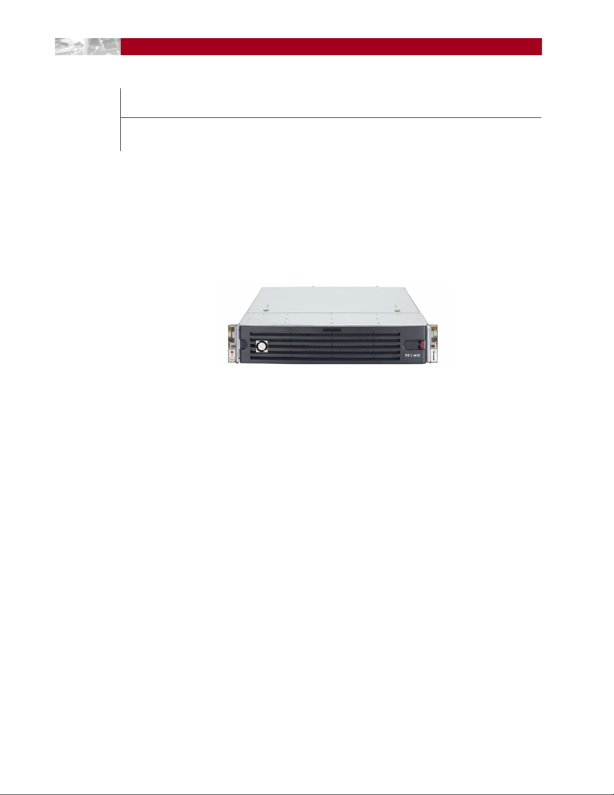
Introduction and Requirements
The Overland Storage REO 4600 disk-based backup and recovery appliance (Figure 1-1)
with Protection OS® software delivers volume and device virtualization, management,
and connectivity capabilities, plus offers both iSCSI and Fibre Channel (FC) connectivity
features.
Figure 1-1: REO 4600 Disk Backup and Recovery Appliance
The VTL uses a Web-based interface and can be easily configured as either a virtual tape
library (VTL) and/or any mix of standalone virtual tape drives, Dynamic Virtual Tape
(DVT) drives, or virtual disks. Using DVT, users can create virtual tape cartridges that
automatically expand or shrink as needed to match the exact capacity requirements of the
backup operation.
The REO 4600 offers optional add-on data compression hardware that provides high
performance compression and decompression capabilities for use with any virtual tape
device. It provides 2:1 or better compression without sacrificing performance.
NOTE: Hardware compression is only available for virtual tape drives; it is not an available option
for disk targets.
Once the hardware card is installed, compression is enabled and is available for all virtual
tape devices on the REO 4600. The also implements in-band host application enable or
disable requests, and monitors the compression status for the virtual tape devices.
NOTE: Hardware compression settings cannot be changed manually.
Reviewing Pre-Installation Requirements
Before attempting to operate the REO 4600 with your backup media servers, verify that
your network meets the minimum requirements specified in the following sections.
10400253-101 01/2010 ©2007-10 Overland Storage, Inc. W 1-1
Page 12

REO 4600 User Guide Introduction and Requirements
Network
For best results, Overland strongly recommends that you use a dedicated GbE network to
share the storage resources on the REO 4600 among multiple backup media servers.
To ensure optimum performance, always use the appropriate patch cables to connect the
REO 4600 to the backup-server storage network. To select the appropriate cables, use the
following guidelines:
• If you intend to use GbE, you must use Category 5e (or better) cables for GbE
connections. You can use either straight-through or cross-over cables.
• If you intend to connect the REO 4600 to a 100BASE-T or faster network, use
Category 5 (or better) shielded cables.
• The maximum length of cable for any Ethernet-based network connection is 328 feet
(100 meters).
NOTE: For smaller environments, you can attach the REO 4600 directly to a single application or
backup server by using standard Category 5e cables without the use of a switch.
Initiators
Initiators are required to communicate with the REO 4600 targets (devices). Each backup
media server that will interface with the REO 4600 must be equipped with a software- or
hardware-based initiator. The REO 4600 supports any computing platform with an
available iSCSI initiator, either in software or using an iSCSI HBA (it must comply with
iSCSI draft 20, version 1.0).
Browser
The REO 4600 GUI is a Web-enabled program that requires the use of cookies, Java
applets, and JavaScript. Make sure that the Web browser you use is configured to allow
these items.
10400253-101 01/2010 ©2007-10 Overland Storage, Inc. W 1-2
Page 13
CHAPTER
Hardware Setup
2
The main steps involved in setting up the REO 4600 include:
1. Activate the warranty coverage.
2. Install the rack rails.
3. Insert the appliance into the rack.
4. Attach the network cables.
5. Attach the appliance to a UPS.
First Things First—Activate Your Warranty!
Before installing your new appliance, it is essential that you activate your Overland
warranty. Technical and warranty support are not available until this is done:
1. Go to the Overland Technical Support web site at:
http://support.overlandstorage.com/
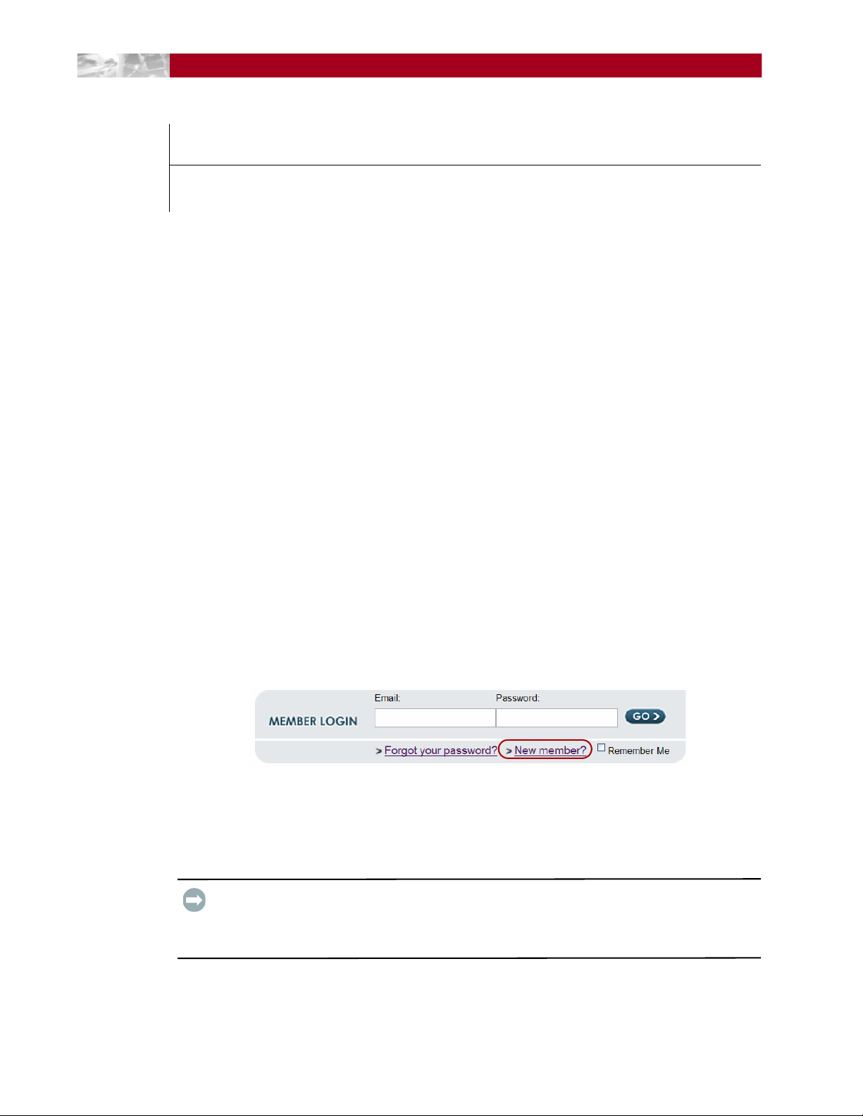
2. At the MEMBER LOGIN (Figure 2-1), use your e-mail address and password to log
in to the site.
NOTE: If you are not yet a member, click “New member?” and follow the instructions. It’s
free and easy!
Figure 2-1: Login and Sign-up Links
3. At the Support Home page menu on the left, select My Products > Add or
Register a Product.
4. Fill in the information and click Submit.
IMPORTANT: Within three business days after registering, you will receive an e-mail from
Overland with your warranty certificate. Carefully review it and verify that the product and
address information is accurate. If any errors are found, e-mail us at:
warranty@overlandstorage.com.
10400253-101 01/2010 ©2007-10 Overland Storage, Inc. W 2-1
Page 14
REO 4600 User Guide Hardware Setup
Installation Preparation
CAUTION: Overland strongly recommends that you install the unit in a clean, air-conditioned
environment with power conditioning and an adequately rated uninterruptible power supply
(UPS). The unit is intended to be grounded.
Unpacking the REO Appliance
The REO 4600 appliance ships with up to twelve disk drives assembled into carriers and
packaged separately.
An Accessory Kit is included containing:
• Power cords
• Rack kit and adaptors
• REO 4600 Quick Start Guide
• REO 4600 Documentation CD
IMPORTANT: Before unpacking the unit, ensure that the area is free from conditions that
cause electrostatic discharge (ESD). Discharge static electricity from your body by touching a
known grounded surface. Also, avoid touching pins, leads, or circuitry.
Installing the Rail Kit
Your REO 4600 appliance comes with a set of slide rails for mounting the chassis in the
19-inch rack. The unit has a 2U form factor.
Each rail assembly consists of three rail members (Figure 2-2 on page 2-3). The inner
member is released from the rail assembly and attached to the appliance. The expandable
outer member along with the embedded middle member is mounted onto the rack.
The rail kit included with the appliance is adaptable for installation in the three major
types of hardware racks:
• Squared-holed RETMA rack on page 2-4
• Round-holed RETMA rack on page 2-4
• Round/Threaded-holed RETMA rack on page 2-5
NOTE: The two-post telco-style rack or a rack less than 32-inches in depth will not support the
REO 4600 appliance.
WARNING: Install multiple units in the rack from the bottom up. Extending a unit that has
empty spaces beneath it might cause the rack to tip and cause injury or damage. Overland
recommends that two people be used to insert or remove a unit.
The rails are not universal. They are stamped LH (left) and RH (right) and must be
mounted on the appropriate side (when facing the rack front).
10400253-101 01/2010 ©2007-10 Overland Storage, Inc. W 2-2
Page 15

REO 4600 User Guide Hardware Setup
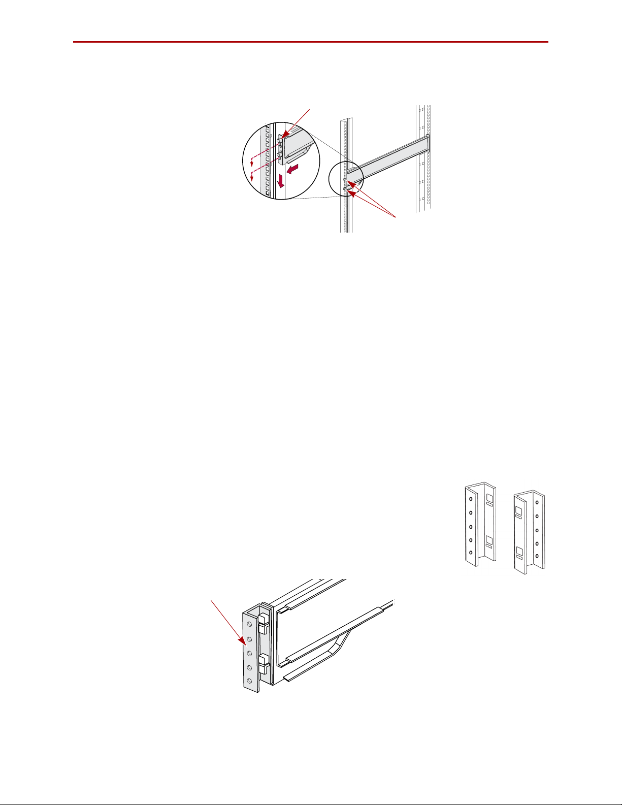
Inner Member Latch
Middle Member Latch
(Hidden)
Middle Member
Outer Member
Screw
Align Rear
Holes to Tabs
Attach the Inner Rails to Chassis
This procedure is required for all three types of racks:
1. Fully extend the rails, push the inner member latch down, and remove the inner
rail (Figure 2-2). Release and slide the middle member back in.
Figure 2-2: Inner Rail Release Clip
2. Identify and mark the screw holes on the rack where the sliding outside rails will
be installed.
NOTE: Be sure rear holes are horizontally in line with the front holes to assure the unit
remains level.
3. Attach the right inner rail (Figure 2-3) as follows:
Figure 2-3: Attach Inner Member
a. Position the rail against the appliance with the appliance locking tabs going
through the holes on the rail
b. Slide the rail toward the front to lock it.
c. Secure the rail with a screw.
4. Repeat Step 3 to install the left inner member.
10400253-101 01/2010 ©2007-10 Overland Storage, Inc. W 2-3
IMPORTANT: Depending on the type of rack you have, continue with the Square-Holed,
Round-Holed, or Round/Threaded-Holed rack installation procedure.
Page 16
REO 4600 User Guide Hardware Setup
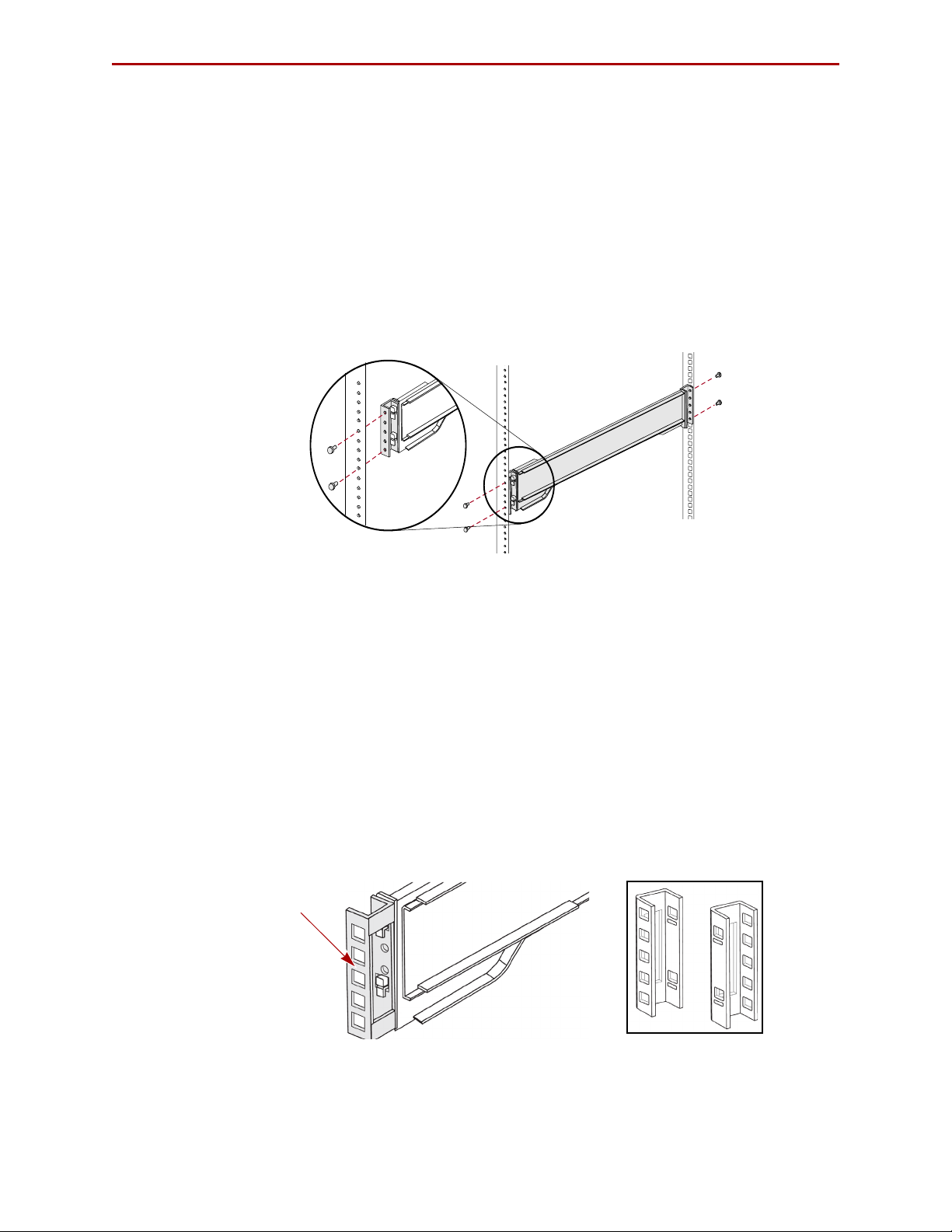
Hooks
Tab
Round-Hole
Adaptor
Squared-Holed Rack Installation
1. Attach left outer rail to the rack (Figure 2-4) as follows:
Figure 2-4: Attaching Front of Rail
a. Position the rail against the inside of the rack front rail with the hooks in line
with the holes.
b. Insert the bracket front into the rack rail and press down so that the hooks
catch.
The spring-loaded tabs will extend into the hole to prevent the rail from
unhooking.
c. Slide the rear segment of the bracket rearward until the hooks are in line with
the correct holes.
d. Insert the bracket rear into the rack rail and press down so that the hooks
catch and the tabs lock.
2. Repeat Step 1 for the left slide rail assembly.
Continue the installation with “Rack Installation” on page 2-6.
Round-Holed Rack Installation (Early
If the adapters in your rail kit
use the following procedure to install
before installing the rails in the rack.
NOTE: These earlier adapters cannot be used with threaded-hole racks.
1. Attach the left round-hole adaptor (Figure 2-5) to the outer
rail:
Models)
resemble the illustration to the right,
the adapters on the outer rails
Figure 2-5: Attach the Early Round-Hole Adaptors
10400253-101 01/2010 ©2007-10 Overland Storage, Inc. W 2-4
Page 17
REO 4600 User Guide Hardware Setup
Round-Hole
Adaptor
a. Position the adaptor stamped “A” at the front of the left outer rail facing
inward.
NOTE: Make sure the “A” stamp is up and the two square holes on the adaptor are
aligned with the hooks on the outer rail.
b. Press the adaptor onto the hooks and slide it upwards until it locks (clicks).
NOTE: The rail buttons will pop into the square holes.
c. Repeat Steps a–b for the rear adaptor (“B”).
2. Facing the rack (Figure 2-6), position the left outer rail on the left side of the rack,
aligning the adaptor holes with the front rack holes being used.
Figure 2-6: Using the Early Round-Hole Adaptors
3. Using the screws from the kit, secure the front of the outer rail to the rack.
4. Slide the rear segment of the bracket rearward until the hooks are in line with the
correct holes.
5. Using the screws from the kit, secure the rear of the outer rail to the rack.
6. Repeat Steps 1–5 for the right outer rail.
Continue the installation with “Rack Installation” on page 2-6.
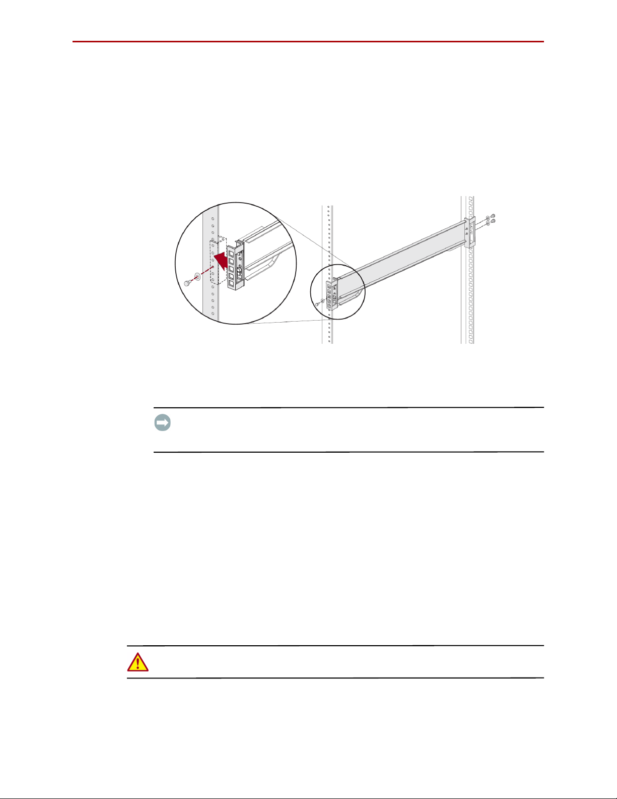
Round/Threaded-Holed Rack Installation
Use the following procedure to install the adapters on the outer rails for round-holed or
threaded-holed racks before installing the rails.
1. Attach the left round-hole adaptor (Figure 2-7) to the outer rail:
Figure 2-7: Attach the Round-Hole Adaptors
a. Position the adaptor stamped “A” at the front of the left outer rail facing
outward.
10400253-101 01/2010 ©2007-10 Overland Storage, Inc. W 2-5
Page 18
REO 4600 User Guide Hardware Setup
NOTE: Make sure the “A” stamp is up and the two square holes on the adaptor are
aligned with the hooks on the outer rail.
b. Press the adaptor onto the hooks and slide it upwards until it locks (clicks).
NOTE: The rail buttons will pop into the square holes.
c. Repeat Steps a–b for the rear adaptor (“B”).
2. With you facing the rack (Figure 2-8), position the left outer rail on the front left
side of the rack, aligning the adaptor front outside the rack holes being used.
Figure 2-8: Using the Round-Hole Adaptors
3. Using a screws and cup washers from the kit, secure the front of the outer rail to
the rack.
IMPORTANT: If you plan to secure the REO 4600 appliance to the rack (highly
recommended), only use one screw and washer now and use the other to secure the
appliance after it is installed.
4. Slide the rear segment of the bracket rearward until the outside of the adaptor is
outside the rail and the hooks are in line with the correct holes.
5. Using the screws and cup washers from the kit, secure the rear of the outer rail
to the rack.
6. Repeat Steps 1–5 for the right outer rail.
Continue the installation with “Rack Installation.”
Rack Installation
Installing the Appliance in the Rack
WARNING: It is recommended that a mechanical lifter (or at least two people) be used to
prevent injury during rack removal and reinsertion.
1. At the front of the rack, pull out the middle members until they lock (click) in the
extended position.
10400253-101 01/2010 ©2007-10 Overland Storage, Inc. W 2-6
Page 19
REO 4600 User Guide Hardware Setup
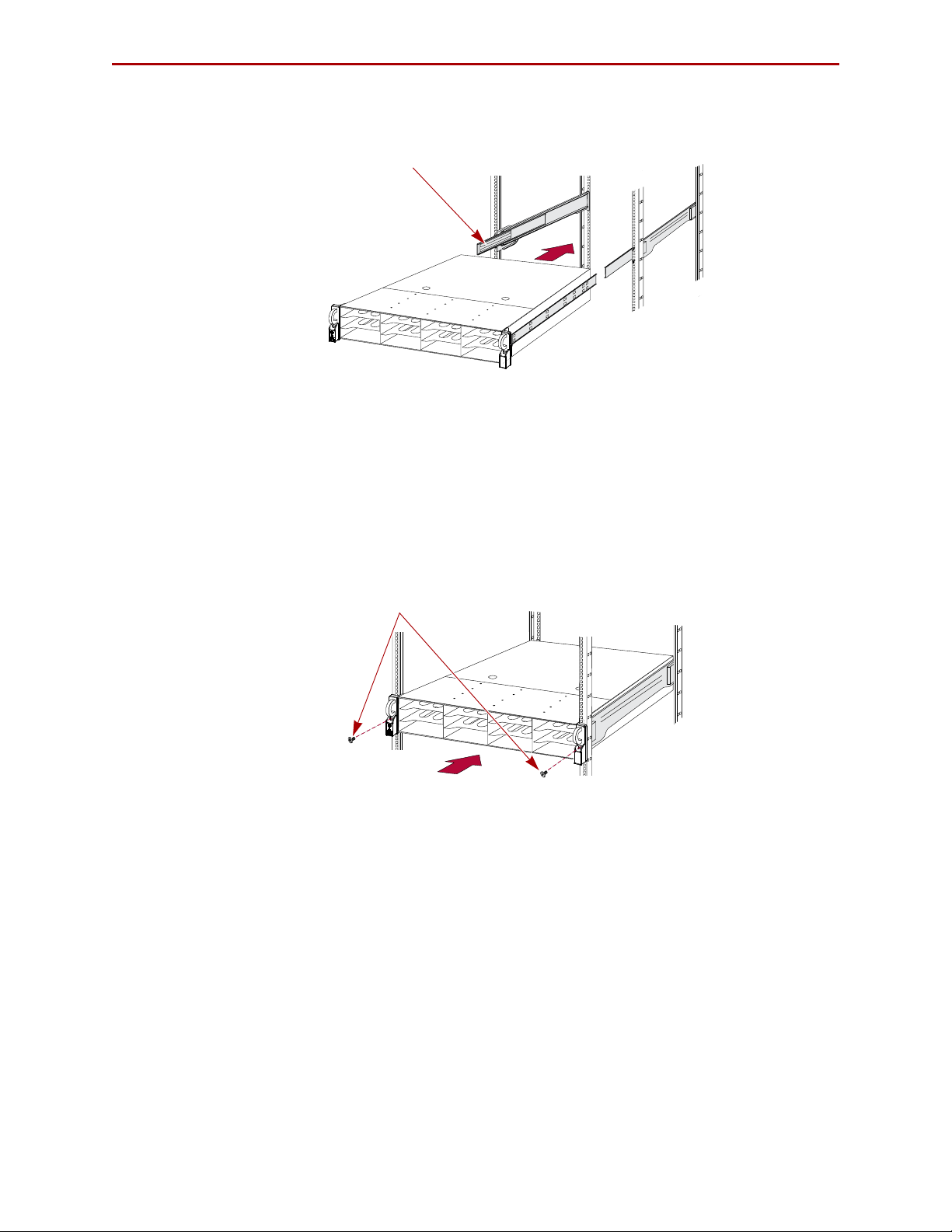
Shuttle
Screws
2. Confirm that the ball-bearing shuttle is all the way to the front of the middle
member (
Figure 2-9).
Figure 2-9: Inserting Appliance Into Rack
3. Using a mechanical lifter or two people, lift the appliance to its install height and
engage the inner members mounted on the appliance with the middle members
protruding from the rack, sliding the appliance into the rack until it stops.
4. Slide the appliance in and out several times to ensure that the rail members slide
smoothly, the locks engage properly, and the appliance does not bind.
If binding occurs, verify that the front and rear flanges are mounted in the correct
holes, readjusting the slide positioning as necessary.
5. Using the two screws provided, secure the appliance flanges to the rack.
Figure 2-10: Secure the Appliance to Rack
Installing Disk Drives
The drives come packed separately. Once the appliance is in the rack, install the drives:
NOTE: Do not remove the disk drives from their carriers. Doing so voids the drive warranty.
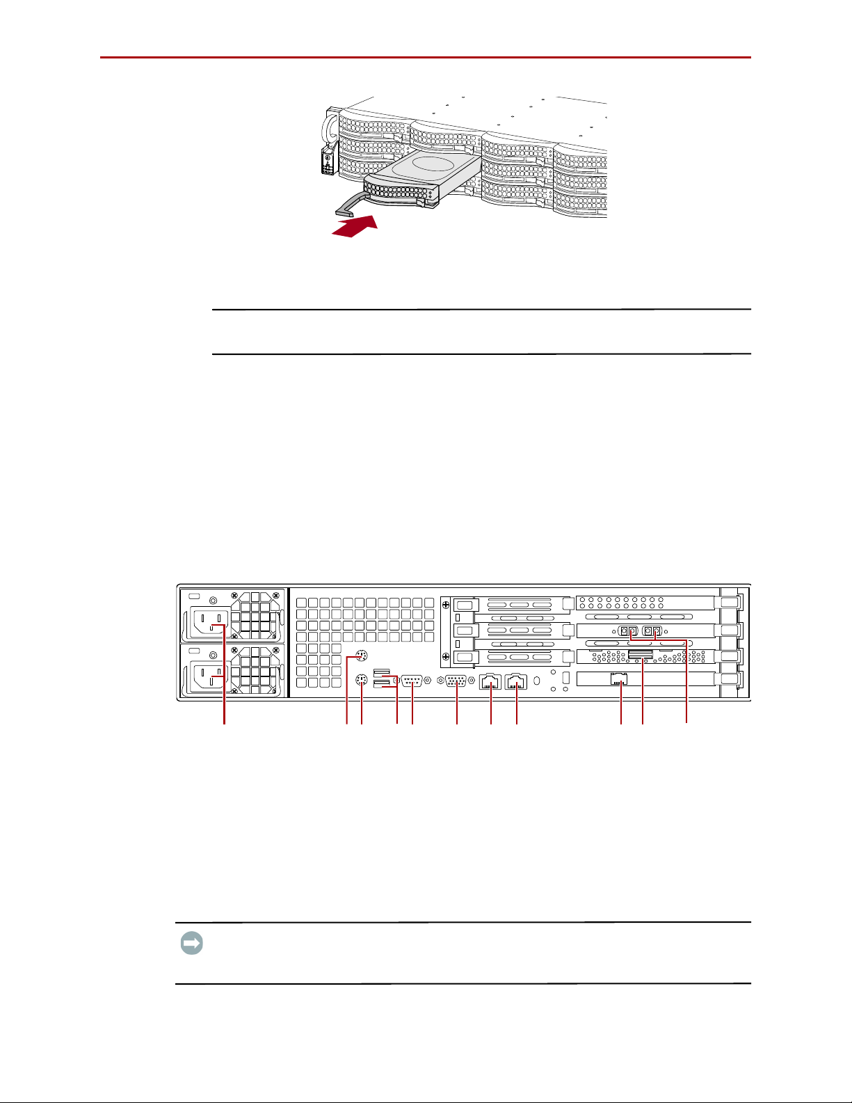
1. Position the drive carrier assembly with the button to the right before you slide it
into the chassis.
2. With the lever open, carefully insert the drive assembly until it completely enters
the bay.
3. Push the lever back in place to lock it (Figure 2-11).
10400253-101 01/2010 ©2007-10 Overland Storage, Inc. W 2-7
Page 20
REO 4600 User Guide Hardware Setup
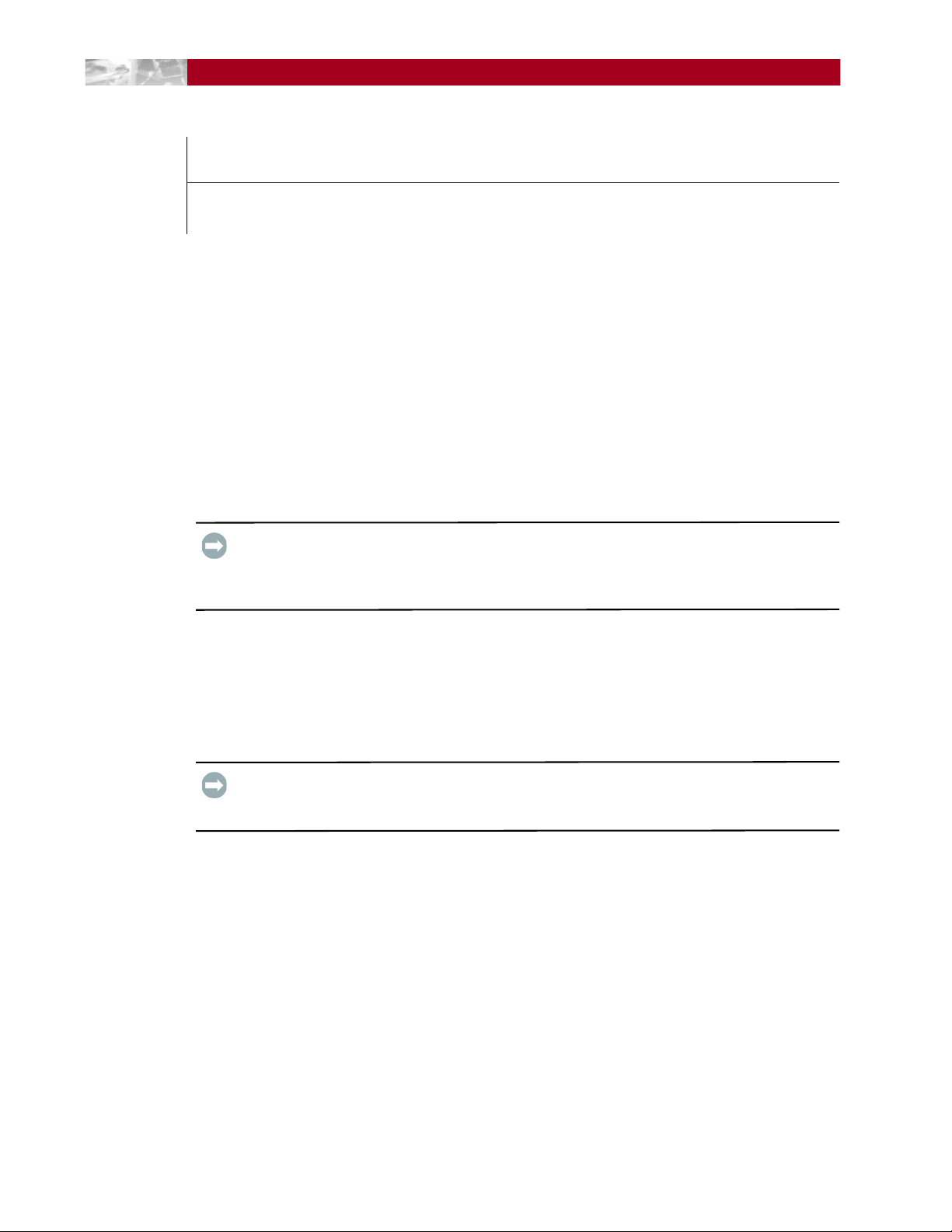
1 - AC Power Connectors
2 - Mouse Port
3 - Keyboard Port
4 - Dual USB Ports
5 - COM Port
6 - Video Port
7 - Data Port 1 (RJ-45)
8 - Data Port 2 (RJ-45)
9 - Management Port
10 - SAS Port
11 - FC Ports (Opt.)
1245678103 9 11
Figure 2-11: Reinserting Drive Carrier
4. Repeat Steps 1–3 for each remaining drive carrier.
IMPORTANT: To maintain proper airflow and cooling, either a drive assembly or a blank
drive carrier must be installed in every slot.
5. Attach the bezel:
a. Insert the left tabs into the holes.
b. Push the right side in until it latches (clicks).
Attaching Cables
All cabling and power connections are located on the rear panel of your REO 4600
appliance (Figure 2-12). Connections are available for Ethernet, USB, and serial cabling.
All unit cooling exhaust is handled through the rear panel.
Once the unit is secured in the rack and the disk drives installed, you are ready to attach
the cables that connect the REO 4600 appliance to your host system and power source.
Figure 2-12. REO 4600 Rear Panel Connections
IMPORTANT: You cannot attach peripherals, such as keyboards, mice, and monitors, directly
to the rear of the REO 4600 appliance. To communicate with the appliance, use a computer
on your network.
10400253-101 01/2010 ©2007-10 Overland Storage, Inc. W 2-8
Page 21

REO 4600 User Guide Hardware Setup
1. Plug the network connection into the Data Port 1.
Using a Category 5e (or better) cable, connect Data Port 1 on the appliance directly
to a network PC or laptop to configure the management port LAN.
2. If a direct data connection is needed, plug the network cable into Data Port 2.
(
Figure 2-12).
3. Attach the two power cords to the AC Power sockets on the REO back panel, but do
not connect the cords to any AC power sources yet.
Powering up the unit is covered in the next chapter.
Connecting a UPS
IMPORTANT: Overland recommends connecting your REO 4600 to an Uninterruptible Power
Supply (UPS).
NOTE: For more information on using a UPS, refer to “Backup Power” on page 3-4.
1. Make sure the REO 4600 is still powered down.
2. Connect the USB cable from the UPS to the USB port on the REO 4600 back panel.
3. Plug the AC power cords from the REO 4600 into the AC sockets on the UPS
10400253-101 01/2010 ©2007-10 Overland Storage, Inc. W 2-9
Page 22
CHAPTER
Powering Up the Appliance
3
The main steps involved in enabling power to the REO 4600 include:
• Making sure that the disks are correctly inserted in the appliance.
• Connecting the power cords to a power source and enabling power.
• Shutting down the appliance.
• Using an Uninterruptible Power Supply (UPS).
Disk Insertion Verification
IMPORTANT: The REO 4600 head unit must be fully populated with drives that are all of the
same capacity. Also, expansion units must be fully populated with drives that are all of the
same capacity. The drives in one unit can be a different capacity than those in other units as long
as all the drives in a single unit are the same size.
Make sure that the disks are seated correctly to prevent an error state during the poweron procedure.
Enabling Power
IMPORTANT: Both power cords must be connected. If one of the cords is disconnected or
malfunctioning, the appliance beeps continuously until the situation is resolved. Overland
recommends that you use separate power mains for the power sources.
Power problems can be the cause of serious failures and downtime on your network.
Ensure that the power input to your system is clean and free from sags and surges to avoid
unforeseen network outages. Overland strongly recommends that you install power
conditioning and an adequately rated uninterruptible power supply (UPS), especially in
areas prone to blackouts, power dips, and electrical storms.
The REO 4600 is intended to be grounded. Ensure it is connected to earth ground during
normal use.
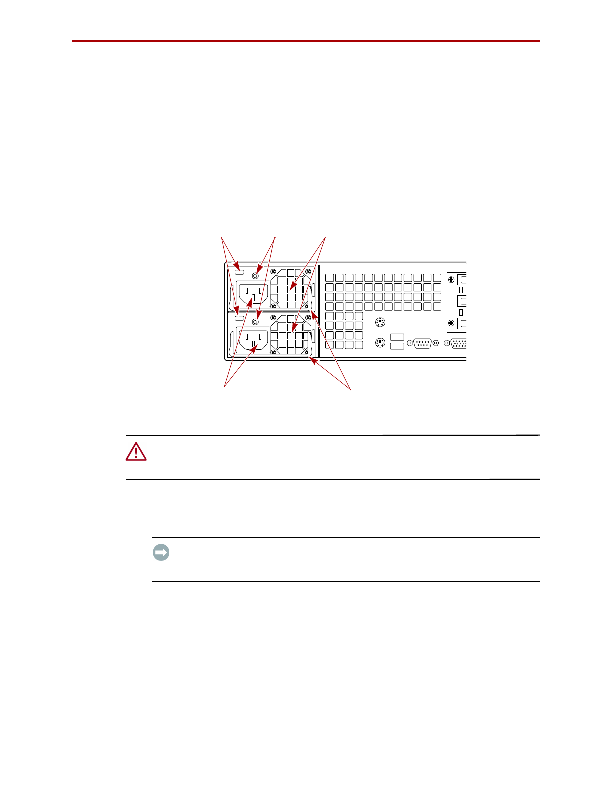
Power Supplies
Each of the two power supply modules contain:
• A socket for an AC line cord.
• A two-color LED for indicating the status of the power supply.
10400253-101 01/2010 ©2007-10 Overland Storage, Inc. W 3-1
Page 23
REO 4600 User Guide Powering Up the Appliance
Fans
Release
Handles
LEDs
AC Sockets
Latches
• When all outputs are available, the LED becomes green.
• If the power supply fails, the LED becomes red.
• A latch for releasing the power supply.
• A handle for pulling the power supply out of the appliance.
• A pair of fans to prevent overheating.
• A feature that verifies the following (if not detected, an alarm signal sounds):
• All output voltages V1 to V5 are within regulation.
• The fans are operating normally.
• The internal temperature of the power supply is normal.
Figure 3-1: Enabling Power to the Appliance
CAUTION: To power on a REO system with an expansion unit, refer to Chapter 8, “Expanding
Capacity.” If you do not complete these steps in this order, the appliance might start in an
error state.
To power up the appliance:
1. Plug the UPS power cord into a separate AC power source and turn the UPS ON.
IMPORTANT: If power is automatically enabled when you attach the UPS cord to an AC
power source, shut down the appliance by pressing the Power button for one second
and then releasing it before continuing with the setup process.
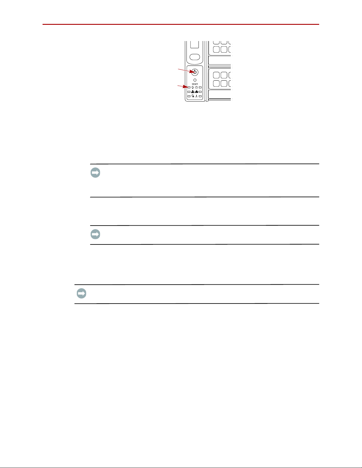
2. To power up the REO 4600, press and hold the Power button for about one second,
which starts the power-up sequence.
The power switch is located in the lower-left corner of the front panel. The power
switch is a momentary contact device that needs to be held no more than one second
to begin the power-up sequence.
10400253-101 01/2010 ©2007-10 Overland Storage, Inc. W 3-2
Page 24
REO 4600 User Guide Powering Up the Appliance
Power
Power
LED
Figure 3-2: Power Button Location
After you turn the power on, the REO 4600 performs a power-on self-test (POST)
process. Following successful completion of the POST, which takes several minutes,
you should hear 3 beep tones spaced about 1 second apart.
If you are unable to hear the tones in your physical environment, wait about five
minutes before continuing.
IMPORTANT: On startup, the appliance might reach an error state and begin an
endless loop of alerts. The pattern (2 beeps separated by a 1-second delay) repeats
every 4 seconds. If this occurs, turn the appliance off and then back on. For more
information, see “Perpetual Loop of Audible Alerts on the Appliance” on page A-12
3. After you hear the POST completion beep tones, proceed to the configuration steps
outlined in the next chapter,
“Configuring Your Appliance” on page 4-1.
IMPORTANT: You must leave the appliance ON while completing the configuration
process for your application and backup media servers.
Shutting Down the Appliance
IMPORTANT: To ensure preservation of data on the REO 4600, you should not turn off the
appliance using the Power button. Always use the Shut Down option located in the GUI.
NOTE: If you are setting up a new appliance and you did not complete the steps in the proper
order or power was automatically enabled, you might not have access to the Shut Down
option in the GUI.
To shut down the appliance via the GUI:
1. Make sure none of the initiators (servers) have active connections.
To determine connection status, check the Initiator Summary page in the GUI.
2. In the GUI, click System > Maintenance.
3. On the Maintenance page, under Shut Down/Restart, click Shut Down.
4. When the confirmation message appears, click OK.
10400253-101 01/2010 ©2007-10 Overland Storage, Inc. W 3-3
Page 25
REO 4600 User Guide Powering Up the Appliance
To shut down the appliance without GUI access:
1. Press and release the Power button on the front of the appliance quickly (1 second
or less) to initiate a graceful software-system shut down process.
2. Wait up to 1-2 minutes to see if the appliance responds.
The power LED turns off after the shutdown process is finished.
3. If the appliance does not shut down after the first attempt, repeat
Steps 1–2 a second time.
CAUTION: Pressing and holding the Power button for 4 seconds or more causes an
immediate hardware shut down that might result in the loss of data on the appliance if there
are any active read-, write-, or management-operations. Whenever possible, turn off the
appliance using the GUI or the graceful shutdown method described earlier. If you must use
the immediate hardware shutdown method, make sure that you first stop all host and
management server-related activity.
Backup Power
In order to protect your data from loss due to sudden power interruption, your REO 4600
supports the use of an external UPS. The unit monitors the UPS via the USB port
(reporting the charge level on the System Summary page). When the REO 4600 senses a
low UPS power condition, it initiates a graceful shutdown that completes before the UPS
runs out of battery power.
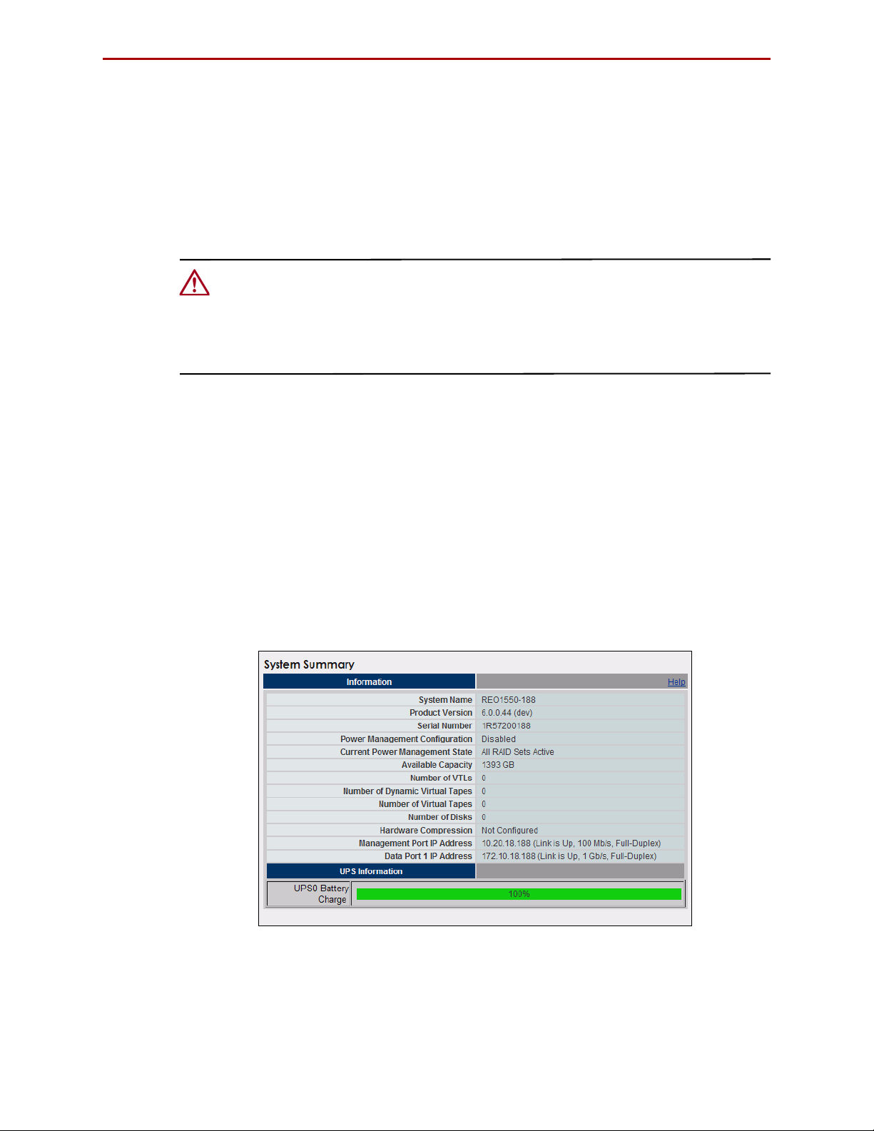
UPS Power Monitoring
When the REO appliance detects that it is connected to a UPS, it displays the UPS
Information (
Figure 3-3) at the bottom of the System Summary page.
Figure 3-3: System Summary Page UPS Information
• When the REO is receiving power from the main AC source, the indicator bar is
green. A complete green bar and 100% indication mean that the UPS battery is fully
charged.
10400253-101 01/2010 ©2007-10 Overland Storage, Inc. W 3-4
Page 26

REO 4600 User Guide Powering Up the Appliance
• When the main AC power is interrupted and the REO is powered by the UPS, the
indicator bar turns red (Figure 3-4). The red bar and the numeric indication grow
smaller as the UPS battery charge goes down.
Figure 3-4: REO Running on UPS Power
• When the primary AC power is restored, the indicator bar turns green. The green
bar and the numeric indication grow toward 100% as the UPS battery recharges
itself.
Behavior When Connected to UPS
A REO 4600 with a UPS works normally as long as the main AC power is supplied. When
the main AC power is interrupted and the REO 4600 detects battery power, it initiates a
graceful shutdown in such a way as to be completed before the battery power runs out.
Once initiated, the shutdown process continues to completion, even if the AC power has
been restored. Upon completion of the shutdown, and when the AC power has been
restored, the REO 4600 does not restart automatically. Use the Power button on the front
panel to restart the REO 4600.
Supported UPS Models
UPS support has been verified with the APC Smart-UPS 2200VA. Other UPS devices that
connect via the same driver can be found at:
http://www.networkupstools.org/compat/stable.html
10400253-101 01/2010 ©2007-10 Overland Storage, Inc. W 3-5
Page 27

CHAPTER
4
Configuring Your Appliance
The main steps involved in configuring your REO 4600 management environment are:
1. Entering default gateway and Management Port addresses.
2. Entering the Data Port information.
3. Entering Fibre Channel and system information.
4. Configuring logon information.
5. Configuring alerts.
6. Setting the applicable time information.
7. Connecting the appliance to the backup media servers, either via iSCSI or Fibre
Channel.
The images shown in the following sections were captured on a Windows system. The
screens might appear slightly different if you are using a UNIX-based system.
Set Up Network Addressing
Before using your REO 4600, you must configure the network communication addresses.
The Management Port connects the REO 4600to the Management LAN. A workstation or
computer connected to the LAN can then be used to manage the REO 4600.
IMPORTANT: The Management Port and both Data Ports must be on a separate subnets.
Logging On
When setting up your REO 4600, you must initially connect to Data Port 1 and configure
the network settings.
1. Directly connect a laptop or other computer to Data Port 1.
2. Configure the NIC in the laptop to be on the 10.0.0.0 network except
for
10.0.0.1.
3. Launch a Web browser on the connected laptop.
4. In your Web browser, connect to the default IP address of 10.0.0.1.
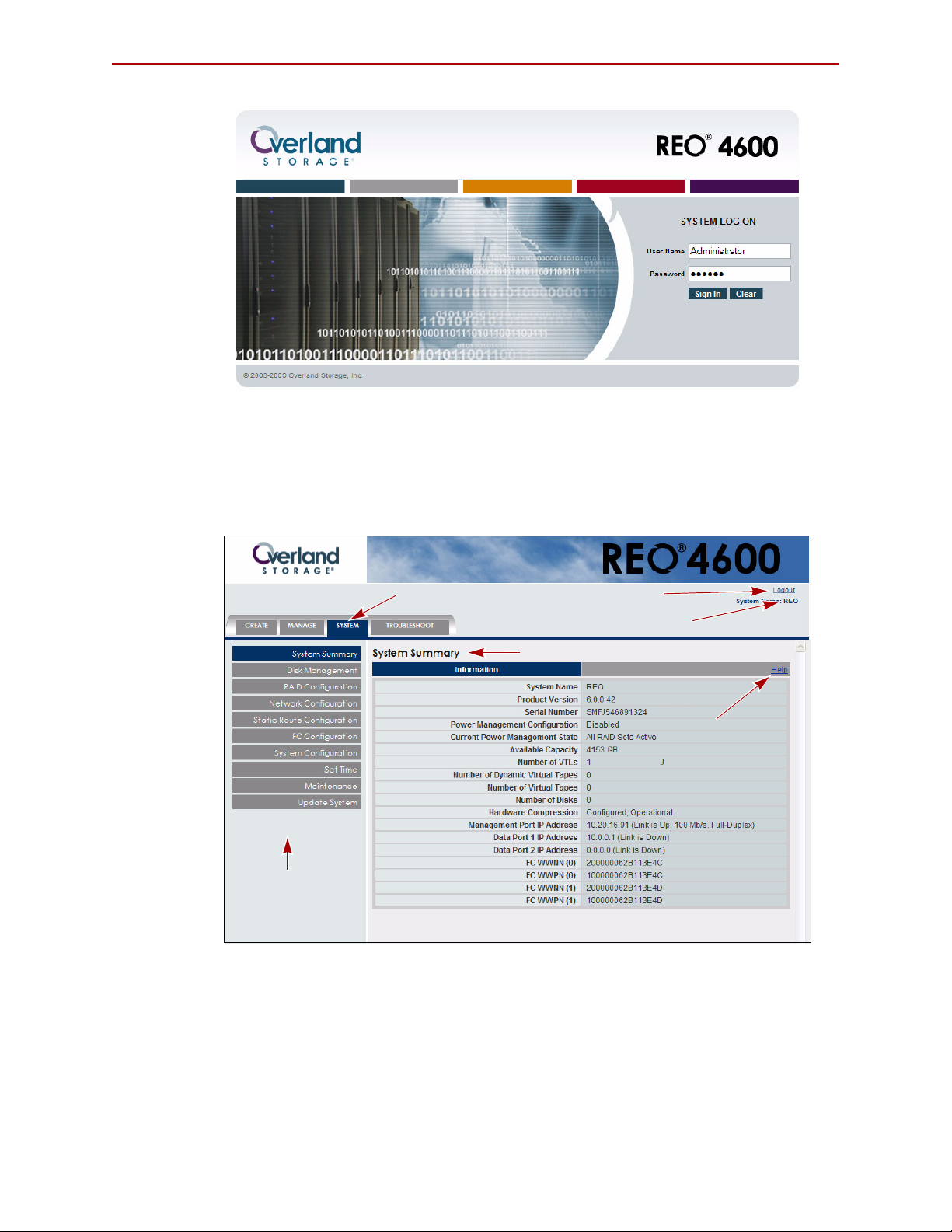
The Login screen is displayed (Figure 4-2):
10400253-101 01/2010 ©2007-10 Overland Storage, Inc. W 4-1
Page 28
REO 4600 User Guide Configuring Your Appliance
Appliance Name
Submenu
Content Page Header
Main Menu Tabs
Buttons
(Content Page)
Logout Link
Help Link
Figure 4-1: REO 4600 Logon Screen
5. Enter the following in case-sensitive format:
• Logon Name: Administrator
• Password: system
The REO 4600 GUI appears (Figure 4-2).
Figure 4-2: REO 4600 Default GUI Screen
When you first access the GUI, it displays the System Summary page. The main menu
tabs are located at the lower left side of the title bar. Selecting a tab name displays the
submenu buttons in the side bar. The content page on the right displays the information
that corresponds to the submenu option you click.
10400253-101 01/2010 ©2007-10 Overland Storage, Inc. W 4-2
Page 29
REO 4600 User Guide Configuring Your Appliance
Entering Configuration Settings for the Management Port
CAUTION: The Management Port MUST be configured.
The REO 4600 is preconfigured to use Data Port 1 as the initial communication
mechanism for your management system. It uses default IP address 10.0.0.1 and subnet
mask 225.225.225.0. Connecting the management system initially to Data Port 1 allows
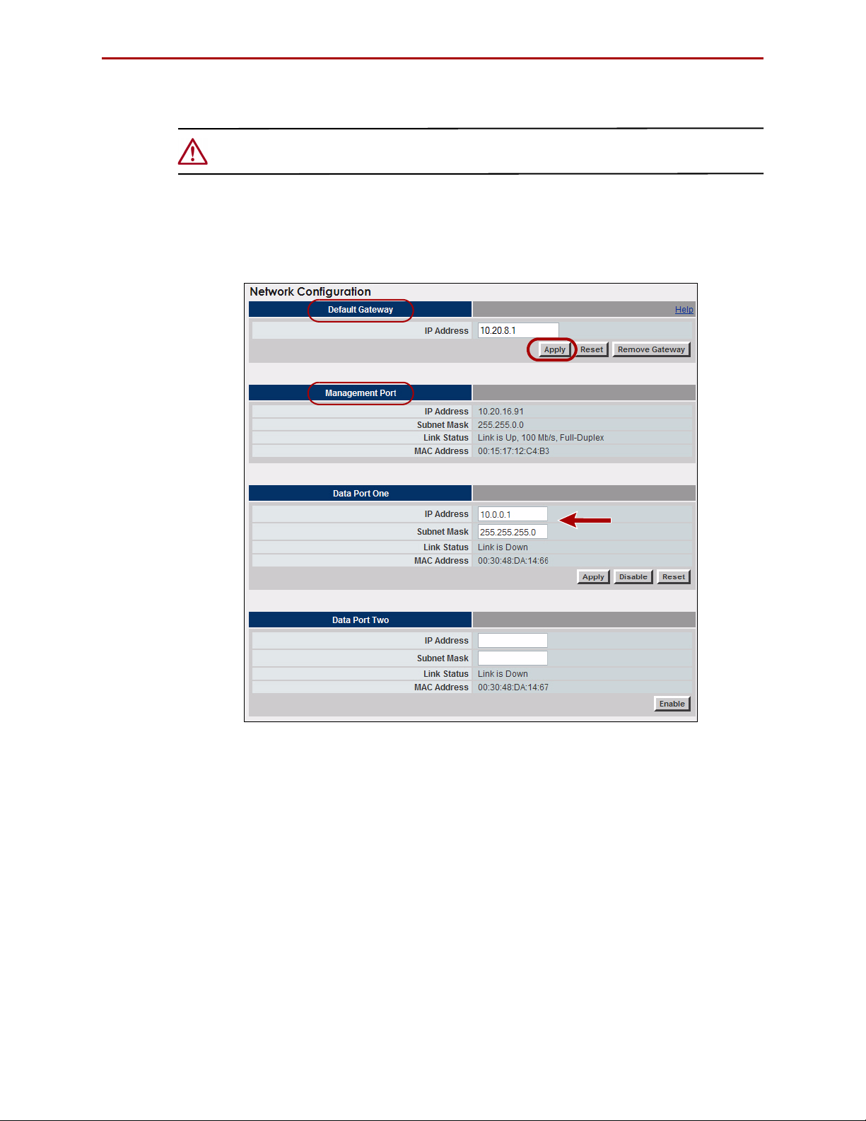
for Management Port configuration (Figure 4-3).
Figure 4-3: Initial Network Configuration Screen
NOTE: You cannot configure the Data Port to which you are currently connected. When you are
connected to Data Port 1 via the default IP, you can only configure the Management Port.
To configure Data Port 1, you must be connected to the Management Port.
1. With the GUI visible in your browser, verify that the System tab is selected.
2. Click Network Configuration to display the option screen.
3. In the Default Gateway section, enter the address you want to use and click
Apply.
4. In the Management Port section, enter the address and subnet mask you want to
use and click Apply.
NOTE: Only when the Management Port has not yet been established does that section
show active Apply, Disable, and Reset buttons.
10400253-101 01/2010 ©2007-10 Overland Storage, Inc. W 4-3
Page 30

REO 4600 User Guide Configuring Your Appliance
5. Click the Logout link (Figure 4-4) on the right in the Title Bar.
Figure 4-4: Logout Link Location
6. Using a Category 5 (or better) cable, connect the Management Port to a switch or
hub on the Management LAN.
7. In a browser on the Management computer, enter the Management Port IP address
set in
Step 4.
8. Logon to the GUI using the same user name and password.
NOTE: If the computer attached to the Management Port is unable to access the GUI,
reconnect the laptop and use the 10.0.0.1 address to double-check the information
you specified for the Default Gateway and Management Port.
Continue the configuration process by configuring the GbE data ports as described in the
next section,
“Configuring the GbE Data Ports.”
Configuring the GbE Data Ports
Data Port 1 and Data Port 2 are GbE data ports used for block-level data transport
between your backup media servers targets and the REO 4600. Data Port
Port
2 are fully interchangeable before configuration.
IMPORTANT: The Management Port is on the Management LAN. Use Data Port 1 and Data
Port 2 on separate subnets of the backup network. Data Port 1 and Data Port 2 each
requires an available static IP address within their respective subnets. The REO can also be
managed via either of the data ports. Entering either data port IP address in your browser displays
the REO 4600 GUI.
The backup media servers must have a GbE port. If you have one or two backup media
servers, you can connect each one directly to one of the data ports on the REO 4600. If you
have more than two backup media servers, you must make these backup media server
connections through a GbE switch.
NOTE: You cannot configure the data port to which you are currently connected. When you are
connected to Data Port 1 via the default IP, you can only configure the Management Port.
To configure Data Port 1, you must be connected to the Management Port.
1 and Data
To configure the GbE ports:
1. At the System tab, click Network Configuration.
Because you are accessing the GUI through the Management Port, those port
options are not changeable.
2. In the Data Port 1 section:
10400253-101 01/2010 ©2007-10 Overland Storage, Inc. W 4-4
Page 31

REO 4600 User Guide Configuring Your Appliance
a. Enter an appropriate static IP address and subnet mask.
b. Click Apply.
3. If applicable, in the Data Port 2 section:
a. Click Enable.
b. Enter an appropriate static IP address and subnet mask.
c. Click Apply.
If you purchased the FC-enabled REO 4600, continue the configuration process by
entering the FC information described in the next section; otherwise, proceed to the
subsequent section,
“Entering the System Information” on page 4-6.
Configuring FC Data Ports
If your REO appliance is set up for FC, configure the FC:
1. At the System tab, click FC Configuration (Figure 4-5).
Figure 4-5: FC Configuration Page
2. For each FC port (the appliance provides two), select the applicable settings from the
Set Link Speed and Set Link Topology lists.
• For link speed, select Auto, 1 GB, 2 GB, or 4 GB.
NOTE: Overland Storage recommends that you configure a fixed speed of 1, 2, or 4 GB.
10400253-101 01/2010 ©2007-10 Overland Storage, Inc. W 4-5
Page 32

REO 4600 User Guide Configuring Your Appliance
• For topology, select Auto, Fabric/Point-to-Point (N_Port), or Loop
(NL_Port).
3. If you want to use a specific loop ID (Hard Alpa), check Enable/Disable box and
enter the desired number.
The following are the valid addresses:
0x01 0x02 0x04 0x08 0x0F 0x10 0x17 0x18 0x1B 0x1D
0x1E 0x1F 0x23 0x25 0x26 0x27 0x29 0x2A 0x2B 0x2C
0x2D 0x2E 0x31 0x32 0x33 0x34 0x35 0x36 0x39 0x3A
0x3C 0x43 0x45 0x46 0x47 0x49 0x4A 0x4B 0x4C 0x4D
0x4E 0x51 0x52 0x53 0x54 0x55 0x56 0x59 0x5A 0x5C
0x63 0x65 0x66 0x67 0x69 0x6A 0x6B 0x6C 0x6D 0x6E
0x71 0x72 0x73 0x74 0x75 0x76 0x79 0x7A 0x7C 0x80
0x81 0x82 0x84 0x88 0x8F 0x90 0x97 0x98 0x9B 0x9D
0x9E 0x9F 0xA3 0xA5 0xA6 0xA7 0xA9 0xAA 0xAB 0xAC
0xAD 0xAE 0xB1 0xB2 0xB3 0xB4 0xB5 0xB6 0xB9 0xBA
0xBC 0xC3 0xC5 0xC6 0xC7 0xC9 0xCA 00xCB 0xCC 0xCD
0xCE 0xD1 0xD2 0xD3 0xD4 0xD5 0xD6 0xD9 0xDA 0xDC
0xE0 0xE1 0xE2 0xE4 0xE8 0xEF
4. Click Apply.
Continue with “Entering the System Information,” next.
Entering the System Information
The System Configuration page under the System tab provides one place to set the System
Name and Logon credentials. It also enables overall e-mail notification or SNMP
notification concerning events and alerts.
1. At the System tab, click System Configuration (Figure 4-6).
10400253-101 01/2010 ©2007-10 Overland Storage, Inc. W 4-6
Page 33

REO 4600 User Guide Configuring Your Appliance
Figure 4-6: Initial System Configuration Page
2. In the System Information section, enter the System Name you want (the default is
“REO”) and click Apply.
Enter up to 16 characters using a mixture of letters, numbers, and hyphens (–).
Overland recommends that you change the default name, especially if you use
multiple appliances on your network.
3. In the Logon Information section, enter user name and password credentials:
IMPORTANT: If you choose to keep Administrator as your user name, Overland
strongly recommends that you change the password to protect your network from
unauthorized users. The user name and password are case-sensitive.
a. User Name (required). Enter a name using up to 30 alphanumeric characters
(do not use colons or spaces). The first character of the name must be either an
upper (A–Z) or lowercase (a–z) alphabetical character.
b. Password (optional, but strongly recommended). Enter a new password using
up to 30 alphanumeric characters (do not use spaces or Ctrl-key characters).
c. Retype Password. Enter the password again.
d. Click Apply.
10400253-101 01/2010 ©2007-10 Overland Storage, Inc. W 4-7
Page 34

REO 4600 User Guide Configuring Your Appliance
4. In the E-mail Notification section, click Enable to display the configuration
options (Figure 4-7) and enter the following:
Figure 4-7: Initial System Configuration Page with E-mail Enabled
a. SMTP Server IP Address. Using dotted decimal notation, enter the IP address
of your mail server.
b. From Address. Enter the e-mail address from which the alert will be sent. This
address must use the same domain as the mail server specified for SMTP Server
IP Address.
c. Address for all messages. Enter the e-mail address to which alerts should be
sent (for example, the e-mail address for the network administrator or the e-mail
list address for a group of backup administrators).
d. Address for critical messages only. Enter the e-mail address to which only
critical alerts should be sent
.
e. To verify that the messaging system is configured correctly, click Test.
If the test e-mail message is not successfully sent and received, correct the
applicable information, and repeat the test. If the test is unsuccessful, make sure
that you are using a valid SMTP Server IP address, and that the address is
working properly.
f. Click Apply.
5. If you use network-management software that takes advantage of SNMP, in the
SNMP Configuration section, click Enable to view the entries (
Figure 4-8):
10400253-101 01/2010 ©2007-10 Overland Storage, Inc. W 4-8
Page 35

REO 4600 User Guide Configuring Your Appliance
a. Read-Only Community String. Enter the name of the string (the default is
public). You can enter up to 256 alphanumeric characters.
IMPORTANT: Because public is the default string for a large number of network
appliances, Overland strongly recommends that you change it.
b. Trap IP Address. Using dotted decimal notation, enter up to four IP addresses
that function as destinations.
c. Click Apply.
d. To verify that the system is configured correctly, click Test Trap.
e. To download the MIB file for this SNMP configuration, press Download MIB.
The compressed, downloaded file mibs.tgz contains the required SNMP MIB for
receiving traps. Place this file in a secure location.
NOTE: The file must be saved with a TGZ extension.
Setting the Local Time
Under the Set Time section (Figure 4-9), you can either set the time manually or connect
to a Network Time Protocol (NTP) server to manage the time for you.
Figure 4-8: Configuring SNMP
10400253-101 01/2010 ©2007-10 Overland Storage, Inc. W 4-9
Page 36

REO 4600 User Guide Configuring Your Appliance
Figure 4-9: Set Time With NTP Disabled
1. Using the drop-down list, select the appropriate local Time Zone and click Apply
just below the list.
IMPORTANT: Set the Time Zone first. This establishes the correct time for the
appliance whether the time is set here, or via NTP server.
The REO 4600 defaults to the UTC (formerly Greenwich Mean Time) time zone. If
you are in a different time zone, you must set the time zone for accurate local time.
This ensures that any communication that occurs (for example, if an E-mail is
automatically generated) reflects the correct date and time for the appliance.
For more information on setting the time, see “Set Time” on page C-21.
2. Set the time on the current appliance:
• To manually set time on this appliance: In the Current Date and Time
section, select the appropriate current time settings and click Apply.
• To set time via NTP server: Set the correct local time, then enter the IP
address of the NTP server on your network, and click Enable NTP. The
Current Date and Time section displays only the current date and time with no
options (Figure 4-10).
Figure 4-10: Set Time With NTP Enabled
10400253-101 01/2010 ©2007-10 Overland Storage, Inc. W 4-10
Page 37

REO 4600 User Guide Configuring Your Appliance
NOTE: To disable NTP server time: Click Disable NTP. The Current Date and Time section
re-displays the date and time options and the Current Network Time section returns
to its original state.
RAID Setup
The REO 4600 ships configured as a RAID 6 with Hot Spare but also supports the basic
RAID
5, RAID 5 with Hot Spare, and RAID 6 configurations. RAID 6 offers two parity
blocks distributed across all disks and provides protection against data loss during an
array rebuild, when a second drive is lost, a bad block read is encountered, or when a
human operator accidentally removes and replaces the wrong disk drive when replacing a
failed drive. You can use the RAID Setup feature under the System tab to select a different
RAID configuration.
CAUTION: When you click Submit, all existing data is deleted during the RAID setup process.
It also takes several minutes to set up a new RAID configuration. It is recommend that the
process be run overnight.
If you do not want to proceed with changes to the RAID configuration, cancel this
operation.
RAID Setup with One or More Expansion Units
When you request the RAID Setup function on a REO head unit with one or more
expansion units connected, the process cleans up and deletes all connected RAID Sets but
only the head unit recreates its RAID Sets. The RAID Sets for each expansion
appliance must be added manually. See
Chapter 8, “Expanding Capacity.”
10400253-101 01/2010 ©2007-10 Overland Storage, Inc. W 4-11
Page 38

CHAPTER
5
Virtual Tape Library Setup
The key feature of the REO 4600 is its ability to emulate a physical type library so your
existing backup software can easily manage the REO appliance, track and move virtual
tape cartridges, and maintain retention policies.
The main steps involved in creating a Virtual Tape Library (VTL) include:
• Adding a virtual tape library and drive type that you want to emulate.
• Setting the target information.
• Identifying the initiator targets.
• Making a backup copy of your configuration.
• Determining the type of RAID Set you want to use.
NOTE: Up to six (6) VTLs can be created on each REO appliance running Protection OS version
6.0.x.
Adding a VTL
1. Click the Create tab. The default screen is the Create Virtual Tape Library screen
(Figure 5-1).
2. Make the necessary changes to the fields as follows:
Figure 5-1: Create Virtual Tape Library Screen
a. In the Descriptive Name section, do one of the following:
10400253-101 01/2010 ©2007-10 Overland Storage, Inc. W 5-1
Page 39

REO 4600 User Guide Virtual Tape Library Setup
• Leave the Automatic check box selected to have the Protection OS
software specify the name of the VTL. It uses the prefix “vl” followed by a
number, beginning with 0, for example, “vl0” for the first VTL.
• To use your own naming convention, clear the check box, in the text box that
appears to the right of the check box (Figure 5-2), type a name using up to 32
alphanumeric characters.
Figure 5-2: Descriptive Name Text Box
b. If desired, select the Emulation Template you want to use as the default
settings for the new VTL.
The template that you select changes the default number in the Drive Count and
Cartridge/slot Count fields. You can manually change any of the default settings.
• Select NEO 2000 to create one (1) drive and 30 cartridges (default).
• Select NEO 4100 to create two (2) drives and 60 cartridges.
• Select NEO 4200 to create four (4) drives and 120 cartridges.
c. In the Drive Type section, select the type of drive to emulate. The drive type you
select determines the default DVT Capacity Limit:
• Select LTO-2 to create drives with DVT Capacity Limit of 200GB.
• Select LTO-3 to create drives with DVT Capacity Limit of 400GB (default).
• Select LTO-4 to create drives with DVT Capacity Limit of 800GB.
d. In the Bar Code Seed section, do one of the following:
IMPORTANT: The bar code seed text cannot be changed once the VTL is created.
Verify your selections before clicking Create.
• Leave the Automatic check box selected to have the Protection OS
software specify the first bar code label and automatically generate
subsequent labels.
• To use your own naming convention, clear the check box and, in the text box
that appears to the right of the check box (Figure 5-3), type the seed code
using six alphanumeric characters. Lowercase letters are converted to
uppercase when the VTL is created.
Figure 5-3: Bar Code Seed Text Box
The sequencing of the codes begins with the last character listed. For example, if
you manually entered a seed of AAAAAA, the next code is AAAAAB. When the
code reaches AAAAAZ, it rolls the second to the last character and starts over
(AAAABA, AAAABB, and so on). If you manually entered a seed of 111111, the
next number would automatically be 111112.
10400253-101 01/2010 ©2007-10 Overland Storage, Inc. W 5-2
Page 40

REO 4600 User Guide Virtual Tape Library Setup
IMPORTANT: If you plan to create VTLs on multiple appliances and associate
them with the same media-management database in your backup software,
make sure to clear the Automatic check box, and manually enter a starting label that
ensures the creation of a unique labeling scheme for the VTL.
For example, you might use SVA000 as the seed for a VTL on REO appliance A,
SVB000 for a VTL on REO appliance B, SVC000 for a VTL on REO appliance C, and so
on. (The automatic option uses the same labeling scheme for all VTLs on each REO
appliance, which results in the same set of labels being reported for each VTL to your
backup software.
e. Still in the Bar Code Seed section, from the Characters list, select the
applicable number of bar code characters (6 or 8) to display to your backup
application.
If you select 8 characters, the system automatically appends two characters to
the label to indicate the drive type selection:
Table 5-1: Bar Code Drive Characters
Drive Type Characters Appended
LTO -2 L2
LTO -3 L3
LTO -4 L4
f. In the Drive Count field, if you want to change the default number of virtual
tape-drives allocated for the VTL, enter the new number in the text box.
g. In the Cartridge/Slot Count box, if you want to change the default number of
virtual tape cartridges (and corresponding slots) allocated for the VTL, enter the
new number in the text box.
The Protection OS automatically creates a Dynamic Virtual Tape device for each
cartridge.
h. Enter the DVT Capacity Limit for each cartridge.
The default value is 400 GB, the same capacity as an LTO-3 cartridge. If you
change the Drive Type, the DVT Capacity Limit default changes to match.
IMPORTANT: Making this value too large will over-subscribe the REO appliance,
which means the VTL could exhaust the available space of the appliance even
though the VTL has remaining capacity. Consider dividing the total remaining capacity
by the number of cartridges in your new VTL to determine an appropriate DVT capacity
limit.
NOTE: After you click Create, you can only increase the number of drives and cartridges
assigned to the VTL. To decrease either setting, the current VTL must be deleted
and a new one created.
3. Click Create. A progress message appears regarding the time required for a REO
appliance to create the VTL.
When the new VTL is created, the VTL Summary screen (Manage tab) is displayed
(Figure 5-4).
10400253-101 01/2010 ©2007-10 Overland Storage, Inc. W 5-3
Page 41

REO 4600 User Guide Virtual Tape Library Setup
Figure 5-4: Current VTL Summary screen Listing New VTLs
Modifying Target Configuration Settings
To view or change the VTL configuration:
1. Under the Manage tab, click VTL Summary.
2. For the appropriate VTL under the Target Configuration heading, click Modify to
view the Modify Target Configuration screen (
IMPORTANT: The default SCSI Product ID automatically identifies the VTL as a NEO
Series device. Do not change this setting unless your backup software requires a
different setting.
Figure 5-5 on page 5-5).
10400253-101 01/2010 ©2007-10 Overland Storage, Inc. W 5-4
Page 42

REO 4600 User Guide Virtual Tape Library Setup
Figure 5-5: Modify Target Configuration Screen
NOTE: If your REO does not support Fibre Channel, the FC LUN column displays “n/a”.
3. If necessary, make any changes to the VTL Settings:
• DVT Capacity Limit
• Drive Count
• Cartridge/Slot Count
• Descriptive Name
• Bar Code String Width
NOTE: The bar code seed cannot be changed once the VTL is created.
4. To change the default target name of a device, type the new name in the iSCSI
Target Name box.
All targets must have an iSCSI name. The REO software automatically enters a
name that begins with the name of the VTL and includes the MAC address of the
device.
10400253-101 01/2010 ©2007-10 Overland Storage, Inc. W 5-5
Page 43

REO 4600 User Guide Virtual Tape Library Setup
5. Before clicking Commit, note the following if you need this information for your
backup software:
• Device Name. Displays the name of the device automatically assigned by the
software.
• FC LUN. Displays the Fibre Channel (FC) logical unit number (LUN)
automatically assigned to the device by the software.
• SCSI SN. Displays the Small Computer System Interface (SCSI) serial number
(SN) automatically assigned to the device by the software.
6. Click Commit.
The VTL Summary screen is redisplayed.
You can now add the initiator access to the VTL by completing the steps outlined in the
next section,
“Adding Initiators.”
Adding Initiators
Now that you created a VTL, you can assign initiator access to it. Initiator access to the
devices (targets) is established via the initiators. You can assign up to 16 initiators to each
VTL device. Standalone devices must first exist before you can assign an initiator to them.
IMPORTANT: Due to iSCSI’s limitations with device sharing, plan your storage system
configuration such that there is one iSCSI initiator to a disk device. If your configuration
requires multiple iSCSI initiator connections to one device, then sharing software is required to
avoid data corruption and connection loss.
To add an Initiator to a VTL:
1. Under the Manage tab, select VTL Summary (Figure 5-6).
Figure 5-6: VTL Summary with Initiator Configuration Highlighted
10400253-101 01/2010 ©2007-10 Overland Storage, Inc. W 5-6
Page 44

REO 4600 User Guide Virtual Tape Library Setup
2. For the appropriate VTL, under the Initiator Configuration heading, click Modify to
view the Initiator Configuration screen (Figure 5-7).
Figure 5-7: Modify Initiator Configuration Screen
3. Click Add Initiator (top left) to view the Add Initiator screen (Figure 5-8).
Figure 5-8: Add Initiator Screen with iSCSI Selected (default)
4. In the Select Connection Type field, click either iSCSI or FC.
5. Select an initiator using one of these methods:
• From the Initiator Names drop-down list, select an existing initiator.
NOTE: If there is only one name in the Initiator Names list and you are using the Internet
Explorer browser on a Windows 2000 system to select it, you may need to select
the name a second time before it will automatically complete the name and
address fields.
• In the iSCSI Initiator Name field, enter a unique name (up to 223
alphanumeric characters) of an authorized target initiator.
10400253-101 01/2010 ©2007-10 Overland Storage, Inc. W 5-7
Page 45

REO 4600 User Guide Virtual Tape Library Setup
NOTE: The fully qualified iSCSI name is assigned by the manufacturer of either the
software initiator or the storage adapter on your backup server. The iSCSI initiator
name entered here must match the name of the iSCSI initiator on the associated
backup server.
If the maximum number of initiators has already been defined for a VTL device,
the iSCSI Initiator Name field is greyed out. You can only add an initiator by using
the drop-down Initiator Names list.
• For an FC initiator (Figure 5-9), in the FC Initiator WWNN and WWPN boxes,
enter the official node and port names of the authorized initiator (host system).
Figure 5-9: Add Initiator Screen with FC Selected
NOTE: You can retrieve the initiator WWNN and WWPN by using the specific FC host
adapter management software utility or by querying the name server on the FC
switch.
6. In the Select Devices for this Initiator section, if you do not want the initiator to
access all devices, select the applicable device from the list.
7. Click Commit to create the initiator.
8. If you want to add another initiator, repeat Steps 3–7.
Displaying VTL Status
To view the status of the VTL:
1. Under the Manage tab, select VTL Summary.
2. For the appropriate VTL, under the Display heading, click Status to view the status
information (
10400253-101 01/2010 ©2007-10 Overland Storage, Inc. W 5-8
Figure 5-10).
Page 46

REO 4600 User Guide Virtual Tape Library Setup
Figure 5-10: VTL Status Display
NOTE: If your device does not support Fibre Channel, n/a is displayed in the FC LUN column.
3. Click Return To VTL Summary at the bottom of the screen when done.
Backing Up the Appliance Configuration
The REO appliance includes a feature that saves all configuration-related information,
such as virtual libraries, devices, and host-system information, to a location specified by
you. (It does not save system or network information.)
After you have completed tasks such as creating targets and initiators, Overland strongly
recommends that you create backup copies of the basic appliance configuration. Overland
also recommends that you complete these steps whenever you add a new library or tape
device or change configuration settings.
1. From the System tab, click Maintenance.
2. Under Save/Restore Appliance Configuration, click Save.
3. At the confirmation message, click OK.
4. At the success message, click Continue.
5. At the standard file save window, select either Open or Save, and click OK.
Depending on your browser settings, you may have to select a location to save the
CFG file.
10400253-101 01/2010 ©2007-10 Overland Storage, Inc. W 5-9
Page 47

REO 4600 User Guide Virtual Tape Library Setup
Restoring Configuration Settings From Backup File
If it ever becomes necessary, you can use the Restore option to reset the to a previously
configured state. Using this option recreates configuration-related information, such as
virtual libraries, devices, and initiators (it does not restore system or network
information).
IMPORTANT: Invoking the Restore feature only restores the REO appliance’s configuration; it
does not restore backup data. All existing data and devices are deleted during restore.
For the restore process, refer to “Restoring a Configuration” on page A-17.
10400253-101 01/2010 ©2007-10 Overland Storage, Inc. W 5-10
Page 48

CHAPTER
Configuring Virtual Devices
6
Using the Protection OS software, you can configure disks on a REO appliance to function
either as standalone disk devices or as virtual tape devices.
The main steps involved in setting up virtual devices on your REO appliance are:
1. Understanding the types of disk and tape virtual devices.
2. Configuring appropriate devices for your applications.
3. Making a backup copy of the information so that your configuration is preserved.
Virtual Device Overview
The Protection OS software pools all the REO disks of each RAID together to create
devices of any size. This way, you can use each device either in its native disk format, a
virtual-tape format, or any combination of the two. You can create up to a total of 64
devices using any combination of disk LUNs and virtual tape devices.
NOTE: If you allocate all available space on the appliances to the devices, the system
automatically sends one critical-level alert regarding the storage pool. If you restart the
appliance, the system automatically sends the message again.
Standalone Disk Devices
At any time, unused disk space can be configured as an independent virtual disk device.
This device can fill all available space on the REO appliance. For example, after all VTLs
are set up, any extra disk space can be configured as a standalone disk for extra storage.
This standalone disk can be as large as 16 TB.
NOTE: Support is available for disk devices that are greater than 2 TB (up to 16 TB).
Creating Standalone Disk Devices
1. Under the Create tab, click Disk (Figure 6-1).
10400253-101 01/2010 ©2007-10 Overland Storage, Inc. W 6-1
Page 49

REO 4600 User Guide Configuring Virtual Devices
Figure 6-1: Create Disk Screen
2. Accept the default size or enter a new Size of Device.
3. Accept the default name or enter a new iSCSI Target Name.
4. Click Create.
The Standalone Device Summary screen is displayed showing the new target disk.
Modifying Standalone Disk Devices
NOTE: Disk devices can only be expanded in size. To make a smaller device, the old device must
first be deleted and then recreated using the smaller size setting.
1. If necessary, under the Manage tab, click Standalone Device Summary
(Figure 6-2).
Figure 6-2: Standalone Device Summary Screen
2. To change the iSCSI target name:
a. Click Modify.
b. Enter a new iSCSI target name.
c. Click Apply.
d. At the message about shutting down initiators, click OK.
The Standalone Device Summary screen is redisplayed.
3. To expand the disk size:
a. Click Expand.
10400253-101 01/2010 ©2007-10 Overland Storage, Inc. W 6-2
Page 50

REO 4600 User Guide Configuring Virtual Devices
b. In the Expand Device By field, enter the number of additional gigabytes you are
adding to the existing size.
c. Click Expand.
d. At the message about shutting down initiators, click OK.
The Standalone Device Summary screen is redisplayed.
4. To remove a disk device:
a. Click Remove.
b. At the warning message (Figure 6-3), click OK (or Cancel).
Figure 6-3: Disk Removal Warning Message
The Standalone Device Summary screen is redisplayed.
Setting the SCSI Time-Out Value in Windows Environments
If you intend to use your REO 4600 in a Windows environment, be aware that there are
certain operating conditions in which disk time-out errors might occur. These errors
usually result in the system reporting a disk failure for the associated REO 4600 disk
drive or drives.
NOTE: These disk time-out errors can occur because the default I/O time-out value for Windows
is 20 seconds, which is not sufficient to support the default iSCSI protocol time-out value
of 60 seconds. When you install and set up your REO 4600, we strongly recommend that
you set this value to 60 seconds.
These errors might be reported as “iSCSIPrt” errors in the System Log of the Event
Viewer. Examples include an Event ID 9, “Target did not respond in time for a SCSI
request,” and Event ID 39, “Initiator sent a task management command to reset the
target.” Other symptoms might include “Lost Delayed Write Data” system error messages
or similar error messages related to the REO 4600 disk drives.
To set the time-out value to 60 seconds:
1. On the Windows system, run regedit.
CAUTION: If you edit the registry incorrectly, you might cause serious problems that
require you to reinstall your operating system. Edit the registry at your own risk. Prior
to making any changes, refer to the following Microsoft Knowledge Base article:
http://support.microsoft.com/default.aspx?scid=kb;en-us;322755
2. In HKEY_LOCAL_MACHINE\System\CurrentControlSet\
Services\Disk, edit or add the TimeOutValue entry (Figure 6-4) to set it to 60
seconds in decimal format (0000003c in hexadecimal).
• To edit the value for the TimeOutValue entry if it already exists, double-click the
entry, enter the new value, and click OK.
10400253-101 01/2010 ©2007-10 Overland Storage, Inc. W 6-3
Page 51

REO 4600 User Guide Configuring Virtual Devices
• To add the TimeOutValue entry if it does not yet exist, right-click anywhere in
the list of values, and then click New > DWORD value. Name the new value
TimeOutValue, and then double-click it to edit the setting.
Figure 6-4: Registry Editor with TimeOutValue Added
Standalone Virtual Tape Devices
If you intend to create virtual tape or dynamic virtual tape devices, note the following:
• As with standard tape devices, a specific driver (on a Windows system) or changes to
a system configuration (on a UNIX system) might be required to operate with your
selected backup software. For more information, check the Overland Web site
(www.overlandstorage.com
software.
• Once a tape virtual device is configured, it cannot be changed into a virtual disk
device.
Creating Standalone Tape Devices
You can create either variable-size dynamic virtual tapes or fixed-sized virtual tapes.
Dynamic Virtual Tapes
1. Under the Create tab, click Dynamic Virtual Tape (Figure 6-5).
) for Application Notes related to your specific backup
Figure 6-5: Create Dynamic Virtual Tape Screen
10400253-101 01/2010 ©2007-10 Overland Storage, Inc. W 6-4
Page 52

REO 4600 User Guide Configuring Virtual Devices
2. Select the Drive Type to emulate from the Drive Type drop-down list: LTO-2,
LTO-3, or LTO-4.
3. Accept the default or enter a new Dynamic Tape Maximum Size.
NOTE: Leave the setting at “0” GB to allow it to use up to 2047 GB (maximum) or all
available space, which ever is smaller.
4. Accept the default or enter a new iSCSI Target Name.
5. Click Create.
The Standalone Device Summary screen is displayed.
Virtual Tapes
1. Under the Create tab, click Virtual Tape (Figure 6-6).
Figure 6-6: Create Dynamic Virtual Tape Screen
2. Select the Drive Type to emulate from the Drive Type drop-down list: LTO-2,
LTO-3, or LTO-4.
3. Accept the default or enter a new Size of Device.
4. Accept the default or enter a new iSCSI Target Name.
5. Click Create.
The Standalone Device Summary screen is displayed.
Modifying Standalone Tape Devices
NOTE: Tape devices can only be expanded in size. To make a smaller device, the old device
must first be deleted and then recreated using the smaller size setting.
1. If necessary, under the Manage tab, click Standalone Device Summary
(Figure 6-7).
10400253-101 01/2010 ©2007-10 Overland Storage, Inc. W 6-5
Page 53

REO 4600 User Guide Configuring Virtual Devices
Figure 6-7: Standalone Device Summary Screen
2. To change the iSCSI target name:
a. Click Modify.
b. Enter a new iSCSI target name.
c. Click Apply.
d. At the message about shutting down initiators, click OK.
The Standalone Device Summary screen is redisplayed.
3. To expand the size of a fixed-sized virtual tape:
NOTE: Since a DVT uses dynamic sizing, it expands (and contracts) its size automatically.
a. Click Expand.
b. In the Expand Device By field, enter the number of additional gigabytes you are
adding to the existing size.
c. Click Expand.
d. At the message about shutting down initiators, click OK.
The Standalone Device Summary screen is redisplayed.
4. To remove a virtual tape device:
a. Click Remove.
b. At the warning message, click OK (or Cancel).
The Standalone Device Summary screen is redisplayed.
Add iSCSI Initiator Access for Standalone Devices
To be able to use a REO virtual device, it must first be connected to an initiator.
1. Under the Create tab, click iSCSI Initiator Access (Figure 6-8).
10400253-101 01/2010 ©2007-10 Overland Storage, Inc. W 6-6
Page 54

REO 4600 User Guide Configuring Virtual Devices
Figure 6-8: Standalone Device Add iSCSI Initiator Screen
2. In the iSCSI Initiator Name field, enter a unique name (up to 223 alphanumeric
characters) of an authorized initiator for the target.
NOTE: The fully qualified iSCSI name is assigned by the manufacturer of either the software
initiator or the storage adapter on your backup server.
The iSCSI initiator name entered here must match the name of the iSCSI initiator on
the associated backup server.
If the maximum number of standalone initiators has already been defined for a
device, the iSCSI Initiator Name field is greyed out. You can only add an initiator by
using the drop-down Initiator Names list.
3. In the Device Name List section, select one or more applicable devices from the
list.
4. Click Create to create access for the initiator.
The Add iSCSI Initiator Access for Standalone Devices screen is reset and
redisplayed.
5. If you want to add access for more iSCSI initiators, repeat Steps 1–4.
Add FC Initiator Access for Standalone Devices
For appliances running Fibre Channel, use the following procedure to add FC initiator
access.
1. Under the Create tab, click FC Initiator Access (Figure ).
10400253-101 01/2010 ©2007-10 Overland Storage, Inc. W 6-7
Page 55

REO 4600 User Guide Configuring Virtual Devices
Figure 6-9: Standalone Device Add FC Initiator Screen
2. In the FC Initiator WWNN and WWPN boxes, enter the official node and port
names of the authorized initiator (host system).
NOTE: You can retrieve the initiator WWNN and WWPN by using the specific FC host adapter
management software utility or by querying the name server on the FC switch.
3. In the Device Name List section, select one or more applicable devices from the
list.
4. Click Create to create access for the initiator.
The Add FC Initiator Access for Standalone Devices screen is reset and redisplayed.
5. If you want to add access for another FC initiator, repeat Steps 1–4.
Configuring a Static Route
A static route is a network path that is dedicated to a specific port and destination: it does
not change. You can configure up to four static routes.
NOTE: The addresses used to specify the route must exist prior to establishing the route.
To establish a static route for the appliances:
1. Enter the IP address of the network destination in the Network Destination field.
The network destination is the port on the remote appliance that the central
appliance uses for communication.
10400253-101 01/2010 ©2007-10 Overland Storage, Inc. W 6-8
Page 56

REO 4600 User Guide Configuring Virtual Devices
Figure 6-10: Adding a Route on the Static Route Configuration Page
2. Enter the subnet mask value associated with this route entry in the Subnet Mask
field (such as 255.255.255.0)
3. Enter the IP address of the gateway associated with the route entry in the
Gateway field.
4. Click Add to add this route.
5. At the two confirmation messages that appear, click OK.
Removing a Route
To remove a single route, select the route and click Remove. To remove all of the routes,
click Remove All. Click OK when the confirmation messages appear to remove the route
or routes from the list.
Making a Backup Copy of the Configuration File
IMPORTANT: Overland recommends that you copy the configuration settings for each of your
REO appliances immediately after you have configured it and store it in a file on your local
network computer for future use.
1. At the System tab, click Maintenance (Figure 6-11).
Figure 6-11: System Maintenance Page
2. In the Save/Restore Appliance Configuration section, click Save.
10400253-101 01/2010 ©2007-10 Overland Storage, Inc. W 6-9
Page 57

REO 4600 User Guide Configuring Virtual Devices
NOTE: The settings you are about to save include all configuration-related information, such
as virtual libraries, devices, and initiators (they do not include system or network
information).
3. A message (Figure 6-12) is displayed alerting you to the time it will take to back up
the files. Click OK to continue (or Cancel).
Figure 6-12: Backup Time Message
4. A second message (Figure 6-13) is displayed showing the name of the backup file.
Click Continue.
Figure 6-13: Popup Dialog with Configuration Filename
NOTE: You may consider changing the name of this file later to something more descriptive
that makes the file easier to identify.
5. At final message, browse to the location on your local computer where you want to
save the file and click Save.
The configuration settings for your REO appliance have been saved to a CFG file in the
location specified.
Restoring Configuration Settings From Backup File
If it ever becomes necessary, you can use the Restore option to reset the REO 4600 to a
previously configured state. Using this option re-creates configuration-related
information, such as virtual libraries, devices, and initiators (it does not restore system or
network information).
IMPORTANT: Invoking the Restore feature only restores the REO appliance’s configuration; it
does not restore backup data. All existing data and devices are deleted during restore.
For the restore process, refer to “Restoring a Configuration” on page A-17.
10400253-101 01/2010 ©2007-10 Overland Storage, Inc. W 6-10
Page 58

CHAPTER
Working With the Appliance
7
This chapter provides a few tips on working with the appliance including:
• Logging on to the Web interface.
• Establish communication with the backup media servers.
• Looking at how dynamic tape devices work.
• Checking communication with other systems or appliances.
• Refreshing the REO 4600 GUI.
• Reviewing how disk drives are numbered.
• Moving an appliance.
Logging On from Any System with Network Access
After you have completed configuration of the appliance, you can access the REO 4600
GUI from any system that has network access to the IP address of the Management Port.
Be aware of the following:
• If you log on from one system and then log on from another system, the REO 4600
GUI automatically logs you off from the first system.
• After an hour of inactivity, the REO 4600 GUI automatically logs you off the system.
• If another user logs on to the REO 4600 GUI, you are automatically logged off.
To log into the GUI from a remote system with network access:
1. In your Web browser, type the IP address assigned to the Management Port for the
REO.
Tip: You can also use the IP addresses assigned to the Data Ports.
2. When the prompt appears, type your user name and password (the defaults are
“Administrator” and “system”) in case-sensitive format.
The REO 4600 GUI is displayed.
IMPORTANT: Overland recommends you change both the user name and password.
Logging Off the GUI
To log off the REO 4600 GUI, click Logout in the upper right corner.
10400253-101 01/2010 ©2007-10 Overland Storage, Inc. W 7-1
Page 59

REO 4600 User Guide Working With the Appliance
FC Ports
Data Ports
1
1
2
Management Port
0
Establishing Communication Between the Systems
Once the basic network connections are configured, you are ready to set up the lines of
communication between the REO 4600 and the backup media servers.
Connecting the REO Ports
If you are using iSCSI connectivity, iSCSI initiators are required on each backup media
server being connected so it can communicate with the iSCSI targets (devices) on the REO
4600. Similarly, FC initiators are required for FC connectivity. Use the following
information to connect the REO 4600 to your backup media servers or SAN (
Figure 7-1: Data, Management, and FC Ports
Figure 7-1).
NOTE: You do not need TOE-equipped (TCP Offload Engine) or special iSCSI-capable GbE HBAs
to work with software initiators. Any standard Network Interface Card (NIC) can serve as
an iSCSI network interface device; however, Overland strongly recommends that you use
GbE for enhanced performance.
1. Determine the type of connection to be used:
• For iSCSI connectivity:
• Connect Data Port 1 (left) directly to a backup media server.
• For additional connectivity, connect Data Port 2 (right) directly to a REO
appliance VTL or NEO PTL.
• If connecting to multiple backup media servers, use a GbE switch connected
to either REO data port.
• For FC connectivity:
• Connect FC Port 0 (left) directly to a backup server or to your FC switch or
hub.
• For additional connectivity, connect FC Port 1 (right) directly to a REO
appliance VTL or NEO PTL or to your FC switch or hub.
2. Install the desired software initiator or storage adapter on the backup media server.
If you are using iSCSI connectivity, use either a software initiator (such as the
Microsoft iSCSI Software Initiator) or an IP storage HBA, (such as the QLogic
4050C). If you are using FC connectivity, make sure that the applicable FC initiator
is installed.
NOTE: For detailed information on various drivers and adapters or for assistance on
assigning targets (REO 4600 devices), see the manufacturer’s documentation. You
can also check the Overland Web site (www.overlandstorage.com) for Application
Notes on initiators.
3. For additional backup systems connecting with the REO appliance, repeat Step 2.
10400253-101 01/2010 ©2007-10 Overland Storage, Inc. W 7-2
Page 60

REO 4600 User Guide Working With the Appliance
Looking at How Dynamic Tape Devices Work
As explained previously, Dynamic Tape devices contract and expand to accommodate the
size of a specific backup job.
When your backup software starts a job, it mounts the Dynamic Tape device as if it were a
physical tape, and then begins the backup process by launching a Write operation. During
this process, if the tape position in the backup software corresponds to a logical-block
address (LBA) that is less than 3, the software treats the device as though it were
overwriting a tape, and the REO 4600 reduces the capacity of the device to 1
appliance then releases the unused storage back into a virtual storage-pool (VSP).
When the backup software reaches an early warning (EW) state (EW is reached when less
than 100
to determine whether it can expand the size of the device:
• It determines how much space is already consumed.
• It determines whether you specified a maximum size for the device.
MB of space remains on the current device), the REO 4600 reviews the following
• If the current consumption exceeds 70 percent of the VSP, the appliance sends a
“warning” message to the e-mail and SNMP addresses you specified for alerts.
• If the current consumption exceeds 90 percent of the VSP, the appliance sends a
“critical” message to the e-mail and SNMP addresses you specified for alerts.
• If you did not (that is, if you used the default entry of 0 which lets the appliance
use up to 2047 GB of the VSP), the appliance attempts to expand the size of the
tape in 10 GB increments until the maximum of 2047 GB is reached.
• If you specified a maximum size, the appliance determines whether expanding
the size of the tape by 10 GB would exceed the specified capacity.
• If the expansion would not exceed the limit, the appliance increases the size
of the tape by 10 GB. If the expansion is successful, an EW is not reported to
the backup software. If the expansion is unsuccessful, the EW is relayed to
the backup software.
• If the expansion would exceed the limit, the appliance increases the size of
the tape by the remaining space. If the expansion is successful, an EW is not
reported to the backup software. If the expansion is unsuccessful, the EW is
relayed to the backup software.
GB. The
Checking Communication with Other Appliances or Systems
The Maintenance Diagnostics page includes a section that lets you check network
connectivity with any system, appliance, and so on, that has an IP address. The REO 4600
GUI uses a ping command to perform this check.
To check communication with another appliance or system:
1. Under Troubleshoot tab, click System Diagnostics (Figure 7-2).
10400253-101 01/2010 ©2007-10 Overland Storage, Inc. W 7-3
Page 61

REO 4600 User Guide Working With the Appliance
00
04
08
01
05
09
02
06
10
03
07
11
Figure 7-2: Troubleshoot System Diagnostics Screen
2. In the Ping an IP Address section, type the IP address of the system that you want
to check in the blank field, and click Ping IP.
The GUI displays a message that indicates whether the ping command succeeded or
failed.
3. To proceed, click Continue.
Refreshing the GUI Display
The REO 4600 GUI does not refresh the display automatically. To view updated
information, click the applicable menu command again to refresh the screen.
IMPORTANT: Do NOT use the Refresh button in your Web browser to update the GUI page.
Reviewing How the Disk Drives are Numbered
Physical numbering (Figure 7-3) begins with the disk in the upper-left corner (disk 00)
and moves from left to right, top to bottom (12 drives total).
Figure 7-3: Physical Disk Drive Numbering
The GUI disk numbering style (Figure 7-4) is slightly different. It starts by numbering the
drive in the upper-left corner as number “1” and then proceeds the same way as the
physical numbering but without the leading zeros.
Figure 7-4: GUI Disk Drive Numbering
10400253-101 01/2010 ©2007-10 Overland Storage, Inc. W 7-4
Page 62

REO 4600 User Guide Working With the Appliance
Power
Button
Reset
Access
Power
NIC 2
Activity
Power
Fail
HDD
Activity
NIC 1
Activity
Overheat
/Fan Fail
Disk Activity
Failure (solid)/
Hot Spare OK
(blinking)
Understanding What the LEDs Represent
The REO appliance uses numerous LED lights for information and as alerts.
Front Panel LEDs
The front of the appliance includes several LED lights (Figure 7-5). If an LED for a port
(network connection) is blinking, it indicates that the port is in use. The LED that
represents power indicates whether power is enabled.
Figure 7-5: Front Panel LEDs
Each disk drive (Figure 7-6) has two LEDs: an upper blue LED for activity and a lower red
LED for either failure (solid) or Hot Spare health (blinking).
Figure 7-6: Disk Drive LED
10400253-101 01/2010 ©2007-10 Overland Storage, Inc. W 7-5
Page 63

REO 4600 User Guide Working With the Appliance
1 - AC Power Indicator
2 - Data Ports Activity
3 - Data Ports Speed
4 - FC Ports Activity/Fault
5 - Mgmt Port Activity/Link
6 - Mgmt Port Speed (see table)
124543 6
Back Panel LEDs
The back panel of the appliance includes several LEDs associated with various ports.
These LEDs indicate the presence of links, activity and speed, as well as faults, on their
corresponding ports.
Figure 7-7. REO 4600 Port LEDs
Table 7-1: Management & Data Port Indicator Display Options
Mgmt & Data Ports LEDs Activity LED Speed LED
No link OFF OFF
Linked at 10 MB GREEN OFF
Linked at 100 MB GREEN GREEN
Linked at 1 GB GREEN YELLOW
Activity at any speed GREEN (Blinking) N/A
Table 7-2: FC Port Indicator Display Options
FC Ports 0 & 1 LEDs Activity/Fault LED
Loss of Sync, no Link AMBER
Fault AMBER (Blinking)
1 GBit/s Link OFF
1 GBit/s Activity (date transfers) GREEN (Blinking)
2 GBit/s Link OFF
2 GBit/s Activity (date transfers) GREEN (Blinking)
4 GBit/s Link OFF
4 GBit/s Activity (date transfers) GREEN (Blinking)
10400253-101 01/2010 ©2007-10 Overland Storage, Inc. W 7-6
Page 64

REO 4600 User Guide Working With the Appliance
Relocating (Moving) an Appliance
IMPORTANT: To ensure preservation of data on the REO 4600, you should NOT turn off the
appliance using the Power button; you should always use the Shut Down option in the GUI.
1. In the REO 4600 GUI, under the System tab, click Maintenance (Figure 7-8).
Figure 7-8: System Maintenance Screen
2. Under Shut Down/Restart, click Shut Down.
3. When the confirmation message appears, click OK.
4. Wait several minutes, and then disconnect the AC line cords from the power mains.
5. Unplug and label all connections, so that you can reattach them using the same
connection configuration.
6. To lessen the weight of the appliance, remove the disk carriers, verifying each slot
and disk carrier is still numbered.
CAUTION: To preserve the configuration and avoid loss of data, you must return each
carrier to the same slot in the appliance after you have moved it. Do not remove the
disk drives from their carriers. Doing so voids the drive warranty.
NOTE: If the slots in the appliance and the disk carriers themselves are not labeled, label
them now so that you know which carrier must be inserted into which slot after you
have moved the appliance to the new location. For information on how the disks and
slots are numbered, see “Reviewing How the Disk Drives are Numbered” on
page 7-4.
a. For each drive assembly, press the button to release the assembly handle.
Figure 7-9: Disk Carrier Removal
10400253-101 01/2010 ©2007-10 Overland Storage, Inc. W 7-7
Page 65

REO 4600 User Guide Working With the Appliance
b. Use the lever to pull the carrier out of the slot.
c. Place the drive assembly on an ESD surface.
d. Repeat Steps a–c for the remaining disk carriers.
7. Remove the appliance from the rack by extending the slide rails and then releasing
the slide locks.
CAUTION: Extending a unit that has empty spaces beneath it might cause the rack to
tip forward or might cause personal injury. Overland strongly recommends that two
people support and slide the unit in the rack.
8. Move the appliance to the new location and insert it into the rack.
9. Reinsert the disk carriers in to the appropriate slots in the chassis.
IMPORTANT: To preserve the configuration and avoid loss of data, you must return
each carrier to the same slot in the appliance after you have moved it.
10. Connect the appliance to the network.
For more information, see “Attaching Cables” on page 2-8.
11. Attach the power cords to the appliance and plug the cords in to an AC power source.
Because the appliance is configured to restart automatically in case of a power
outage, connecting it to the power source automatically invokes the start process.
IMPORTANT: If you do not complete the preceding steps in the order shown, the
appliance might start in an error state.
If the appliance starts in an error state (that is, you are unable to access the GUI), use the
steps outlined under
“Shutting Down the Appliance” on page 3-3 to shut down the
appliance. Then turn the appliance ON by pressing and holding the Power button for no
more than one (1) second.
10400253-101 01/2010 ©2007-10 Overland Storage, Inc. W 7-8
Page 66

CHAPTER
SAS Connections
8
This chapter explains how to expand the capacity of a REO 4600 appliance. It describes
how you can add up to four expansion arrays to expand the performance capacity.
IMPORTANT: To ensure data integrity, back up the data on the appliance before you perform
any of these procedures.
Attaching Expansion Arrays
Additional storage can be added by installing one to four SnapServer EXP expansion
arrays to a REO 4600 head unit.
CAUTION: If you intend to attach more than one expansion array, we recommend you attach
only one at a time to the REO 4600 and let the REO 4600 recognize it before connecting the
additional expansion arrays.
Expanding Capacity
1. Power off the REO 4600 head unit (and followed by any expansion arrays attached).
2. Using the installation instructions provided with the new expansion array, install
the unit in the rack, attach the cables, and power it ON.
CAUTION: It is critical to the process that you set up the hardware and power ON the
expansion arrays before you power ON the REO 4600 head unit.
Figure 8-1: Rear Panel, Expansion Array
3. Power ON the head unit.
Wait while the system reboots.
4. If additional expansion arrays are being added, repeat Steps 1–3.
10400253-101 01/2010 ©2007-10 Overland Storage, Inc. W 8-1
Page 67

REO 4600 User Guide Expanding Capacity
5. Once all new expansion arrays are attached, log on to the GUI, and under the
System tab, click Disk Management (Figure 8-2).
Figure 8-2: Disk Management Screen
6. To add all the newly installed storage, including any Free drives in the head unit,
click Add New Storage.
CAUTION: If any RAID sets exist on the expansion arrays, they are deleted during this
process as new RAID sets are built. This can take a long time and requires a reboot,
so it is recommended that no backup jobs be running.
The system adds all the additional storage to the storage pool, which is also reflected on
the VTL Summary or Standalone Device Summary pages. You can now use the Create tab
menu items to create additional devices or expand the capacity of existing ones.
10400253-101 01/2010 ©2007-10 Overland Storage, Inc. W 8-2
Page 68

CHAPTER
9
IMPORTANT: This chapter provides information about the hardware compression feature
that is an optional, add-on component for the REO 4600 appliance.
The REO 4600 with the data compression hardware card installed offers high performance
compression and decompression capabilities for use in virtual tape library applications. It
provides 2:1 or better compression without sacrificing performance.
NOTE: Hardware compression is only available for virtual tape drives; it is not an available option
for disk targets.
Using Compression
As soon as the compression card is installed, compression is enabled and is available for all
virtual tape devices. The REO 4600 implements in-band host application enable or disable
requests, and reports the compression status for the virtual tape devices.
Hardware Compression
NOTE: Hardware compression settings cannot be changed manually.
GUI Screens Impacted
Before the optional hardware compression card is installed, the System Summary screen
under the System tab shows “Not Configured” in the Hardware Compression field. Once
the card is successfully installed, the caption changes to “Configured, Operational.”
NOTE: Should the card fail, the entry would change to “Configured, Not Operational.”
Error Messages
Fatal errors occur if the compression card is not detected during power-up, fails POST, or
reports an error. These errors are reported out-of-band (e-mail alerts and SNMP traps).
Hardware
The hardware compression card contains four (4) compression/decompression engines. It
provides stateless compression and decompression using an enhanced version of the LZS
(eLZS) algorithm that prevents expansion of the compressed data.
Each one of the individual engines can be programmed to either compress or decompress
data. The card doesn't have any internal memory to hold the user data. The data is
transferred from an external input memory buffer using Direct Memory Access (DMA),
10400253-101 01/2010 ©2007-10 Overland Storage, Inc. W 9-1
Page 69

REO 4600 User Guide Hardware Compression
routed to one of the idle compression/decompression engines by the Field-Programmable
Gate Array (FPGA), verified once the operation is complete, then transferred to an
external output memory buffer also using DMA.
The compression card contains a command register that is loaded (by the software
application) with descriptors specifying the operation to be executed: compression or
decompression, source and destination locations, or where to store the completion status.
This allows up to four (4) compression/decompression operations to be executing
concurrently. There are no special requirements to handle simultaneous compression and
decompression operations.
Compression Algorithm
The eLZS compression algorithm used by the compression card is similar to the
compression algorithm used by the LTO tape drives, as they share the same roots with the
original LZS algorithm. Generally, eLZS yields slightly better compression performance
for typical backup data sets (data that generally compresses in the 2:1 to 4:1 range), while
LTO yields slightly better compression for data sets that have higher compression ratios,
e.g., bit-mapped picture files.
This small difference between these two compression algorithms is significant only for
applications where the data stored in a virtual tape cartridge must be copied to an
equivalent physical tape cartridge. For these applications, the application will need to
reduce the total capacity of the virtual tape cartridge to 90% of the total capacity of the
physical tape cartridge to ensure that all the data can be copied.
10400253-101 01/2010 ©2007-10 Overland Storage, Inc. W 9-2
Page 70

APPENDIX
A
Alerts
Basic Troubleshooting
As you troubleshoot the appliance, keep the following guidelines in mind:
• Always use the GUI Shut Down/Restart option to shut down the appliance, NOT the
appliance Power button, to prevent data stream disruption.
• Never remove the chassis cover while it is operating.
• If an expansion unit does not work, make sure that all connections are secure.
The REO appliance continuously monitors its performance and routinely checks for
failures. If you use the messaging options, an e-mail message or Simple Network
Management Protocol (SNMP) trap (or both) is sent whenever the Status of a RAID
volume becomes anything other than OK. Each alert that is sent reports the status of all
volumes on the appliance.
Each RAID alert includes the REO appliance's system name (found under the System
Configuration page in the GUI), the serial number of the appliance that issued the alert,
and the description of the alert. The appliance S/N is the serial number displayed on the
physical unit, so for the head unit it's simply the REO S/N and for expansion units it's the
Enclosure S/N.
The RAID alert included in the body of the e-mail/SNMP message has the following
format:
System: <system name> Chassis S/N: <chassis serial number> - <event
description>
If you use the messaging option, an alert is sent via e-mail or SNMP (or both) in the
following situations.
10400253-101 01/2010 ©2007-10 Overland Storage, Inc. W A-1
Page 71

REO 4600 User Guide Basic Troubleshooting
List of Appliance-Specific Alerts
The following is a list of the alerts.
SNMP Trap ID E-Mail Subject E-Mail Body and SNMP Trap Description
ALERT_TEST n/a Server Name: <SystemName>, Serial
Number: <UnitSerialNumber>. SNMP test
trap generated from the GUI interface
ALERT_DYNAMIC_
TAPE_CAPACITY_SAFE
ALERT_DYNAMIC_
TAPE_CAPACITY_
CRITICAL
ALERT_DYNAMIC_
TAPE_CAPACITY_
WARNING
ALERT_GENERAL_
CAPACITY
ALERT_RAID_UNIT_
ADDED
ALERT_RAID_UNIT_
REMOVED
Device Event, Unit SN:
<UnitSerialNumber>.
Device Event, Unit SN:
<UnitSerialNumber>.
Device Event, Unit SN:
<UnitSerialNumber>.
Storage Pool Event, Unit SN:
<UnitSerialNumber>.
ALERT: RAID UNIT ADDED Server Name: <SystemName>, Serial
ALERT: RAID UNIT REMOVED Server Name: <SystemName>, Serial
Server Name: <SystemName>, Serial
Number: <UnitSerialNumber>. Remaining
Capacity Level: Safe
Server Name: <SystemName>, Serial
Number: <UnitSerialNumber>. Remaining
Capacity Level: Critical <percentage>
Server Name: <SystemName>, Serial
Number: <UnitSerialNumber>. Remaining
Capacity Level: Warning <percentage>
Server Name: <SystemName>, Serial
Number: <UnitSerialNumber>. Safe level
Alert: Percent used: <percentage>, Total
Capacity (GB): <capacity>
Available Capacity (GB): <capacity
Number: <UnitSerialNumber>. Controller
<number>, <HOT SPARE, RAID5>
PU:<number> ADDED
Number: <UnitSerialNumber>. Controller
<number>,
REMOVED
<RAID5> PU:<number>
ALERT_RAID_UNIT_OK ALERT: RAID UNIT OK Server Name: <SystemName>, Serial
Number: <UnitSerialNumber>. Controller
<number>, <RAID5> PU:<number> OK
ALERT_RAID_UNIT_
INITIALIZING
ALERT_RAID_UNIT_
VERIFYING
ALERT_RAID_UNIT_
DEGRADED
ALERT_RAID_UNIT_
REBUILDING
10400253-101 01/2010 ©2007-10 Overland Storage, Inc. W A-2
ALERT: RAID UNIT
INITIALIZING
ALERT: RAID UNIT VERIFYING Server Name: <SystemName>, Serial
ALERT: RAID UNIT DEGRADED Server Name: <SystemName>, Serial
ALERT: RAID UNIT
REBUILDING
Server Name: <SystemName>, Serial
Number: <UnitSerialNumber>. Controller
<number>, <RAID5> PU:<number>
INITIALIZING
Number: <UnitSerialNumber>. Controller
<number>, <RAID5> PU:<number>
VERIFYING
Number: <UnitSerialNumber>. Controller
<number>, <RAID5> PU:<number>
DEGRADED
Server Name: <SystemName>, Serial
Number: <UnitSerialNumber>. Controller
<number>, <RAID5> PU:<number>
REBUILDING
Page 72

REO 4600 User Guide Basic Troubleshooting
SNMP Trap ID E-Mail Subject E-Mail Body and SNMP Trap Description
ALERT_RAID_UNIT_
INOPERABLE
ALERT_RAID_UNIT_
INITIALIZATION_
COMPLETE
ALERT_RAID_UNIT_
VERIFICATION_
COMPLETE
ALERT_RAID_UNIT_
REBUILDING_COMPLETE
ALERT_HOT_SPARE_DISK_C
ONDITION
ALERT_HOT_SPARE_DISK_P
RESENT
ALERT_HOT_SPARE_DISK_N
OT_PRESENT
ALERT: RAID UNIT
INOPERABLE
Server Name: <SystemName>, Serial
Number: <UnitSerialNumber>. Controller
<number>, <RAID5> PU:<number>
INOPERABLE
ALERT: RAID UNIT
INITIALIZATION COMPLETED
Server Name: <SystemName>, Serial
Number: <UnitSerialNumber>. Controller
<number>, <RAID5> PU:<number>
INITIALIZATION COMPLETED
ALERT: RAID UNIT
VERIFICATION COMPLETED
Server Name: <SystemName>, Serial
Number: <UnitSerialNumber>. Controller
<number>, <RAID5> PU:<number>
VERIFICATION COMPLETED
ALERT: RAID UNIT REBUILD
COMPLETED
Server Name: <SystemName>, Serial
Number: <UnitSerialNumber>. Controller
<number>, <RAID5> PU:<number>
REBUILD COMPLETED
ALERT: HOTSPARE DISK
CONDITION
Server Name: <SystemName>, Serial
Number: <UnitSerialNumber>. Controller
<number>, HOTSPARE <REMOVED,
ACTIVATED, FAILED>
ALERT: HOTSPARE PRESENT Server Name: <SystemName>, Serial
Number: <UnitSerialNumber>. Controller
<number>, HOTSPARE PRESENT
ALERT: HOTSPARE NOT
PRESENT
Server Name: <SystemName>, Serial
Number: <UnitSerialNumber>. Controller
<number>, HOTSPARE NOT PRESENT
10400253-101 01/2010 ©2007-10 Overland Storage, Inc. W A-3
Page 73

REO 4600 User Guide Basic Troubleshooting
List of Generic SNMP Alerts (Traps)
The following lists the generic SNMP traps that you might see.
Trap Additional Information
Cold Start Trap Starting snmpd (issuing
2005-09-20 07:33:30 172.20.16.93(via UDP: [10.20.16.93]:32784) TRAP, SNMP v1,
community public
NET-SNMP-TC::linux Cold Start Trap (0) Uptime: 0:00:00.03
service snmpd start) generates the following Cold Start trap:
nsNotifyShutdown Shutting down snmpd (issuing service snmpd stop) generates the following
nsNotifyShutdown trap:
2005-09-20 07:30:39 172.20.16.93(via UDP: [10.20.16.93]:32781) TRAP, SNMP v1,
community public
NET-SNMP-MIB::netSnmpNotificationPrefix Enterprise Specific Trap (NET-SNMPAGENT-MIB::nsNotifyShutdown) Uptime: 17:54:44.69
NOTE: Restarting snmpd (issuing service snmpd restart) generates both of the preceding traps.
nsNotifyRestart Modifying the SNMP configuration parameters through the GUI sends a SIGHUP to
snmpd, which causes it to re-read its conf files and generate the following
nsNotifyRestart trap:
2005-09-20 07:38:54 172.20.16.93(via UDP: [10.20.16.93]:32791) TRAP, SNMP v1,
community public
NET-SNMP-MIB::netSnmpNotificationPrefix Enterprise Specific Trap (NET-SNMPAGENT-MIB::nsNotifyRestart) Uptime: 0:02:58.05
10400253-101 01/2010 ©2007-10 Overland Storage, Inc. W A-4
Page 74

REO 4600 User Guide Basic Troubleshooting
Trap Additional Information
Generate linkUp • When you start or restart snmpd, it generates the corresponding linkUp and linkDown
traps for all network interfaces (Note that ifIndex contains the interface index number):
2005-09-20 07:39:54 172.20.16.93(via UDP: [10.20.16.93]:32791) TRAP, SNMP v1,
community public
SNMPv2-SMI::mib-2.88.2 Enterprise Specific Trap (1) Uptime: 0:03:58.06
SNMPv2-SMI::mib-2.88.2.1.1 = STRING: "Generate linkUp"
SNMPv2-SMI::mib-2.88.2.1.2 = "" SNMPv2-SMI::mib-2.88.2.1.3 = ""
SNMPv2-SMI::mib-2.88.2.1.4 = OID: RFC1213-MIB::ifOperStatus.1
SNMPv2-SMI::mib-2.88.2.1.5 = INTEGER: 1 RFC1213-MIB::ifIndex.1 = INTEGER: 1
2005-09-20 07:39:54 172.20.16.93(via UDP: [10.20.16.93]:32791) TRAP, SNMP v1,
community public
SNMPv2-SMI::mib-2.88.2 Enterprise Specific Trap (1) Uptime: 0:03:58.06
SNMPv2-SMI::mib-2.88.2.1.1 = STRING: "Generate linkUp"
SNMPv2-SMI::mib-2.88.2.1.2 = "" SNMPv2-SMI::mib-2.88.2.1.3 = ""
SNMPv2-SMI::mib-2.88.2.1.4 = OID: RFC1213-MIB::ifOperStatus.2
SNMPv2-SMI::mib-2.88.2.1.5 = INTEGER: 1 RFC1213-MIB::ifIndex.2 = INTEGER: 2
2005-09-20 07:39:54 172.20.16.93(via UDP: [10.20.16.93]:32791) TRAP, SNMP v1,
community public
SNMPv2-SMI::mib-2.88.2 Enterprise Specific Trap (1) Uptime: 0:03:58.06
SNMPv2-SMI::mib-2.88.2.1.1 = STRING: "Generate linkUp"
SNMPv2-SMI::mib-2.88.2.1.2 = "" SNMPv2-SMI::mib-2.88.2.1.3 = ""
SNMPv2-SMI::mib-2.88.2.1.4 = OID: RFC1213-MIB::ifOperStatus.3
SNMPv2-SMI::mib-2.88.2.1.5 = INTEGER: 1 RFC1213-MIB::ifIndex.3 = INTEGER: 3
• If you enable a port on the Network Configuration page, it generates the following linkup trap:
2005-09-20 07:54:54 172.20.16.93(via UDP: [10.20.16.93]:32791) TRAP, SNMP v1,
community public
SNMPv2-SMI::mib-2.88.2 Enterprise Specific Trap (1) Uptime: 0:18:58.12
SNMPv2-SMI::mib-2.88.2.1.1 = STRING: "Generate linkUp"
SNMPv2-SMI::mib-2.88.2.1.2 = "" SNMPv2-SMI::mib-2.88.2.1.3 = ""
SNMPv2-SMI::mib-2.88.2.1.4 = OID: RFC1213-MIB::ifOperStatus.2
SNMPv2-SMI::mib-2.88.2.1.5 = INTEGER: 1 RFC1213-MIB::ifIndex.2 = INTEGER: 2
Generate linkDown If you disable a port on the Network Configuration page, it generates the following
linkDown trap:
2005-09-20 07:51:54 10.20.16.93(via UDP: [10.20.16.93]:32791) TRAP, SNMP v1,
community public
SNMPv2-SMI::mib-2.88.2 Enterprise Specific Trap (1) Uptime: 0:15:58.13
SNMPv2-SMI::mib-2.88.2.1.1 = STRING: "Generate linkDown"
SNMPv2-SMI::mib-2.88.2.1.2 = "" SNMPv2-SMI::mib-2.88.2.1.3 = ""
Authentication
Failure Trap
SNMPv2-SMI::mib-2.88.2.1.4 = OID: RFC1213-MIB::ifOperStatus.2
SNMPv2-SMI::mib-2.88.2.1.5 = INTEGER: 2 RFC1213-MIB::ifIndex.2 = INTEGER: 2
If you submit a request that contains an invalid community string, it generates the
following trap:
2005-09-21 09:44:36 172.20.16.93(via UDP: [10.20.16.93]:32840) TRAP, SNMP v1,
community public
NET-SNMP-TC::linux Authentication Failure Trap (0) Uptime: 23:15:51.83
10400253-101 01/2010 ©2007-10 Overland Storage, Inc. W A-5
Page 75

REO 4600 User Guide Basic Troubleshooting
Using the Log Files
The REO 4600 creates and maintains log files that contain diagnostic information
intended for use by Overland Storage Technical Support in troubleshooting issues you
might encounter. The logs are updated every 60 seconds, with new information appended
to the beginning of the applicable file a new log generated and the old log saved as a
previous version. When the maximum log file size is reached, previous information is
deleted so that new information can be added.
NOTE: When using Microsoft Internet Explorer (IE) as your browser, later versions of IE require a
confirmation before downloading a file. The first time you try to download the log file, a
security bar appears at the top of the page requiring you to approve the download.
Because IE interrupts the actual download, it will fail this first time. Simply download the
file again. On this and each sequential download request, the file should download
correctly as detailed below.
To create and view the log files:
1. In the left pane, under Troubleshoot tab, click System Diagnostics.
2. In the Support Request File section (Figure A-1), click Save.
Figure A-1: Save/Restore Appliance Configuration Section
3. At the message about the time it will take to create the log, click OK.
4. When the message appears (Figure A-2) that indicates a TGZ file was successfully
created, click Continue, and then save the file to a location on your management
system.
Figure A-2: Successful Log File Creation Message
IMPORTANT: If you are using Windows Server 2003 or Windows XP, be aware that the
file extension might be changed to TAR, which prevents the file from opening
correctly. Manually change the extension to the original TGZ extension.
5. After the file is saved, the Overland support representative will guide you
through the log to find the applicable information or ask you to use your e-mail
program to send the file to Overland Support.
10400253-101 01/2010 ©2007-10 Overland Storage, Inc. W A-6
Page 76

REO 4600 User Guide Basic Troubleshooting
Tip: To view a file on a Windows system after you have downloaded it, Overland Storage
recommends that you use WordPad, because it displays the configuration
information in an easy-to-use format (see Figure A-3).
Figure A-3: Log File Displayed in WordPad
6. If asked, use your e-mail application to forward the TGZ log file to:
support@overlandstorage.com
Windows Application Event Log Errors
A GetDriveInfo Failure! error can occur when drives are reserved under Backup Exec.
When Backup Exec cannot get access to a drive for a backup job, it will attempt to retry.
After a period of time, if no drives become available, Backup Exec gets stuck in a
continuous loop of reporting errors. These can be seen in the Windows Event Viewer in the
Application section. Backup Exec must be reset to get back to a good state.
This can be resolved by using schedule-based data movement policies on the REO
appliance to ensure that all server backup jobs are completed before any policies start.
Unable to Access the Appliance
To troubleshoot a loss of access to the appliance:
1. Check the LED lights on the appliance.
If lights are not on, check all connections between the appliance and the power
source.
2. Make sure that all applicable IP addresses are correct.
3. Make sure the network cables are properly installed.
The network cables must be securely attached at all connections. If the cables
appear to be properly attached but the problem persists, try different cables.
Appliance Does Not Start Correctly
To determine why the appliance does not start, use the GUI to restart the REO appliance.
For information on restarting the appliance even if you do not have access to the GUI, see
“Shutting Down the Appliance” on page 3-3.
If this does not solve the problem, contact Customer Support at Overland Storage. For
contact information, see
10400253-101 01/2010 ©2007-10 Overland Storage, Inc. W A-7
“Customer Support” on page F-1.
Page 77

REO 4600 User Guide Basic Troubleshooting
Unable to Log On to the GUI
If you are unable to log on to the GUI, it could be one of these problems:
• The privacy setting is set too high. The GUI is a Web-enabled program that requires
the use of cookies; setting the privacy or security option too high prevents the
program from working correctly.
• You are entering the logon name and password incorrectly.
To troubleshoot GUI login problems
• Make sure that you are entering the logon name and password correctly; they are
case sensitive.
The GUI uses the following defaults for the logon name and password:
Name: Administrator
Password: system
• If you are able to log on, but then are logged off unexpectedly, make sure that you
are the only person accessing the GUI.
For more information, see “Unexpectedly Logged Off” on page A-11.
• If you are using Windows Server 2003, perform the steps outlined in the section
“Internet Explorer Does Not Redirect from IP Address on Windows Server 2003.”
• If you are unable to access the GUI in Internet Explorer running on any version of
Windows other than Windows Server 2003, perform the steps outlined in the section
“Internet Explorer Does Not Redirect from IP Address on Windows Server 2003.”
Internet Explorer Does Not Redirect from IP Address on Windows Server 2003
If you access the GUI using Internet Explorer running on Windows Server 2003, you
might see a blank screen (
to which you are trying to connect.
Figure A-4: Blank Screen Possible After Entering Valid IP Address
This happens because Internet Explorer has an enhanced security configuration that is
enabled by default in Windows Server 2003. This setting does not allow the server to
redirect the IP address to the correct location.
To prevent this from occurring, you need to add the IP address for the appliance to the list
of trusted sites for this server.
Figure A-4) after you enter a valid IP address for the REO 4600
Reset Internet Explorer Security Settings
1. Launch Internet Explorer.
2. In the Tools menu, click Internet Options.
3. On the Privacy tab, move the slider to Medium (or lower).
10400253-101 01/2010 ©2007-10 Overland Storage, Inc. W A-8
Page 78

REO 4600 User Guide Basic Troubleshooting
4. To save your changes, click OK.
GUI Stops Responding or Displays a Refresh Error
When you are working in the GUI, one of the following situations might occur:
• If the GUI stops responding unexpectedly, it might be because a failure occurred on
the appliance. (When a failure occurs and a RAID volume moves into an
INOPERABLE status, the system remains inaccessible while the controller
attempts to recover the volume.) If the system stopped responding, complete the
steps outlined under “Addressing an Unresponsive GUI.”
• If you click a Submit button and you get an error about using the Refresh button or
no response is taken, it might be because your browser is not set to allow the use of
Java applets and scripts. If the error message appeared, complete the steps outlined
under “Addressing a Refresh Error Message” on page A-9. If the system stopped
responding, complete the steps outlined under “Addressing an Unresponsive GUI.”
Addressing an Unresponsive GUI
To address an unresponsive GUI
1. Stop using the GUI for approximately five minutes.
IMPORTANT: If you continue to try and invoke a response from the GUI, it might
increase the recovery time.
2. If access to the GUI returns, use the Disk Management page to check the status of
each volume, and then take
• If the status is INOPERABLE, complete the steps outlined under
“Troubleshooting a Disk Drive Problem” on page A-15.
• If the status is OK, resume normal operation. If you are using RAID 5 or RAID 6,
you can also execute a Verify to ensure that the volume is functioning correctly.
3. If access to the GUI does not return, shut down the appliance using the steps
outlined under
appliance.
“Shutting Down the Appliance” on page 3-3, and then restart the
Addressing a Refresh Error Message
Complete the applicable steps for your browser. This section describes procedures for
Internet Explorer and for Mozilla.
To enable scripting in Internet Explorer
1. Launch Microsoft Internet Explorer.
the applicable action.
2. In the Tools menu, click Internet Options.
3. On the Security tab (Figure A-5), click Custom Level.
10400253-101 01/2010 ©2007-10 Overland Storage, Inc. W A-9
Page 79

REO 4600 User Guide Basic Troubleshooting
Figure A-5: Internet Options Security Tab
4. In the Scripting section (Figure A-6), under Scripting of Java applets, select
Enable, and click OK.
Figure A-6: Enabling Java Scripting
To enable scripting in Mozilla
1. Launch Mozilla Firefox.
2. In the Tools menu, click Options.
3. Click the Web Features icon.
10400253-101 01/2010 ©2007-10 Overland Storage, Inc. W A-10
Page 80

REO 4600 User Guide Basic Troubleshooting
4. Select the Enable JavaScript check box (Figure A-7), and click OK.
Figure A-7: Mozilla Web Features Options
Out of Resources Message When Trying to Create a VTL
If you try to create a VTL and the process fails (see the following error message), it might
because of one of the following:
• You have used the maximum number of tape drives or tape cartridges.
• The appliance could not create one of the VTL components (changer, drive, or
cartridge).
• The appliance has used the maximum number of logical volumes allowed.
• The appliance could not open and initialize the tape changer.
• The appliance could not save the configuration file for the VTL.
• If using a REO 4600 with a hardware compression card installed, the compression
card might have failed.
Unexpectedly Logged Off
When you are using the GUI, you should be aware of the following:
• If you log on from one system and then log on from another system, the GUI
automatically logs you off from the first system.
• If another user logs on to the GUI, you are automatically logged off. A message
similar to the preceding one appears.
• After an hour of inactivity, the GUI automatically logs you off the system.
Unable to Connect to the Disks via Windows Explorer
If you are unable to access the disks on the appliance, it might be because the system or a
disk on the appliance is malfunctioning.
10400253-101 01/2010 ©2007-10 Overland Storage, Inc. W A-11
Page 81

REO 4600 User Guide Basic Troubleshooting
To troubleshoot a disk access problem:
1. Make sure that the appliance is turned on and that all cables are correctly
connected.
2. Make sure that you can view other disks from the same initiator.
If not, there might be a problem with a cable or the Ethernet connection.
3. Make sure that you can view the targets (REO 4600 devices) from the initiator.
a. Log on to the GUI.
b. In the left pane, on the System Menu, click Disk Management.
c. Verify that the Status of each volume and disk is OK (Figure A-8), which
indicates that the target is functioning correctly.
Figure A-8: Disk Management Screen
Perpetual Loop of Audible Alerts on the Appliance
On startup, the appliance might reach an error state and begin an endless loop of audible
alerts. The pattern (2 beeps separated by a 1-second delay) repeats every 4
If the REO 4600 reaches this error state, turn the appliance OFF and then back ON again.
The cause of this error state might also be a LAN cable is not connected to the
Management Port.
Disabling the Audible Alarm on the Appliance
If a power supply fails or detects an issue with the appliance, an audible alarm sounds. If
you do not have the spare component needed to correct the situation, remove the power
supply from the appliance to disable the alarm.
1. Disconnect the AC line cord from the applicable power supply on the back of the
appliance and from the power mains.
seconds.
10400253-101 01/2010 ©2007-10 Overland Storage, Inc. W A-12
Page 82

REO 4600 User Guide Basic Troubleshooting
2. Slide the release latch to the right, pull out the hinged extraction handle, and use
the handle to pull the power supply out of the appliance.
3. Replace the power supply as soon as possible.
Recover System Page Appears in the GUI
If the GUI displays the Recover Inoperable System screen, it indicates that the RAID set
associated with a controller is damaged or unavailable. This can occur if one disk fails in a
RAID
0 configuration, two disks fail in a RAID 5 configuration, or three disks fail in a
RAID
6 configuration. While this makes the appliance temporarily unusable, you can use
the Recover System screen to correct the situation.
Figure A-9: Recover Inoperable System Screen
NOTE: The Display DM button does not appear on the page if the REO cannot properly
communicate with the RAID controller. When present, this button allows you to see the
status of your RAID arrays on the Disk Management System Recover Mode page
(Figure A-10). You cannot take any actions from that page; to return to the Recover
System page, you must click Back on your browser.
10400253-101 01/2010 ©2007-10 Overland Storage, Inc. W A-13
Page 83

REO 4600 User Guide Basic Troubleshooting
Figure A-10: Disk Management System Recover Mode Screen
1. Make sure that all disks are inserted in the appliance.
2. If you are using an Expansion Array, make sure that it is connected to the appliance.
3. Click Save to save a copy of the existing log files to a safe location.
For more information, see “Using the Log Files” on page A-6.
4. Click Restart to shut down and restart the appliance.
5. If the Recover System page appears again after you restart the appliance and log
on, click Restart a second time.
6. If the Recover System page appears again after you restart the appliance a second
time, click the applicable RAID button to re-create the volume configuration.
CAUTION: Clicking one of the RAID buttons invokes a Volume Setup, which destroys
all existing data.
7. When the confirmation message appears, click OK to continue.
8. If the Recover Inoperable System page appears again after you select a RAID
option and log on, click the applicable RAID button a second time, and click OK
when the confirmation message appears.
9. After the RAID rebuild is complete, the EULA screen appears. Highlight the
Accept radio button and click Continue, and then click Continue on the
confirmation page.
10400253-101 01/2010 ©2007-10 Overland Storage, Inc. W A-14
Page 84

REO 4600 User Guide Basic Troubleshooting
If you see a Recover Impaired System screen (Figure A-11), follow the instructions on the
screen to try and recover the system.
Figure A-11: Recover Impaired System Screen
Troubleshooting a Disk Drive Problem
When there is a problem with a disk drive, its Status on the Disk Management page is
reported as EMPTY or FAILED.
The first step you can take is to rebuild the volume that contains the disk drive in question
(RAID
5 or RAID 6), or re-create a Hot Spare (RAID 5 with Hot Spare or RAID 6 with Hot
Spare).
The next step is to replace the applicable disk with a spare disk.
10400253-101 01/2010 ©2007-10 Overland Storage, Inc. W A-15
Page 85

REO 4600 User Guide Basic Troubleshooting
Rebuilding a RAID Volume (Without Hot Spare)
When an issue arises with a disk in a RAID configuration, the disk in question is
designated as FAILED or EMPTY (most likely FAILED) and the volume shows a Status of
Degraded (Figure A-12).
Figure A-12: Disk Management Screen Showing Degraded Volume Status
NOTE: Correct identification of the failed drive is critical to this process. Make sure you correctly
identify the failed drive before proceeding. Shutting down the appliance is not necessary
for a disk swap.
1. Contact Overland Storage Technical Support to arrange for a new drive (under
warranty) to be shipped to you.
2. When your drive arrives, follow the supplied instructions to remove the FAILED
drive and replace it with the new drive.
3. Under the System tab, click Disk Management.
The new replacement drive displays a Rebuild status and drive color on the page is
yellow to indicate REBUILDING (Figure A-13).
Figure A-13: Disk Management Screen During Rebuild
10400253-101 01/2010 ©2007-10 Overland Storage, Inc. W A-16
Page 86

REO 4600 User Guide Basic Troubleshooting
Re-creating a Hot Spare (RAID With Hot Spares)
When an issue arises with a disk in a RAID with Hot Spare configuration, the disk in
question is designated as FAILED or EMPTY (most likely FAILED), and the volume has a
status of Rebuild on the Disk Management page. The Hot Spare disk (usually in Slot 12)
will turn from black to yellow to show that it is the drive that is being rebuilt.
When the FAILED drive has been replaced, it becomes the Hot Spare.
Purchasing a Spare Disk Drive
1. Note the serial number of your REO 4600, which is located on the exterior of the
appliance.
2. Contact your local reseller or contact Customer Support at Overland Storage.
For contact information, see “Customer Support” on page F-1.
Impact of a Power Outage
If the facility in which your REO appliance is installed experiences an interruption in
power, the appliance will automatically run through the power-up sequence when power is
restored.
Restoring a Configuration
You can use the Restore option to reset the appliance to a previously configured state.
Using this option re-creates configuration-related information, such as virtual libraries,
devices, and initiators (it does not save system or network information).
IMPORTANT: Using the Restore option only restores the REO appliance’s configuration; it
does not restore backup data. All existing data and devices are deleted during restore.
To restore a configuration
1. In the left pane, under System Menu, click Maintenance.
2. In the Save/Restore Appliance Configuration section (Figure A-14), click Restore.
Figure A-14: Save/Restore Appliance Configuration Section
3. When the confirmation message appears, click OK.
10400253-101 01/2010 ©2007-10 Overland Storage, Inc. W A-17
Page 87

REO 4600 User Guide Basic Troubleshooting
4. On the Upload Configuration File screen (Figure A-15), type the path name to
point to the configuration file that you saved previously (or click Browse to point to
it), and then click Submit.
Figure A-15: Upload Configuration File Screen
5. When the message appears that indicates the restoration process was successful,
click Continue.
6. When the message appears that prompts you to log back on the appliance, click
Logon.
7. Re-enter any applicable network and system information.
10400253-101 01/2010 ©2007-10 Overland Storage, Inc. W A-18
Page 88

APPENDIX
B
Capacities, Requirements and Limits
NOTE: Check the Overland Storage web site for the most current specifications.
This appendix lists the specifications for the appliance.
Storage Capacity
Disk Drives & Raw Capacity 12 TB (12 - 1 TB SATA disk drives) or
7.2 TB (12 - 600 GB SAS disk drives)
RAID Levels RAID 5 (with and without Hot Spare) or
RAID 6 (with and without Hot Spare)
Interfaces
Host Two GbE Ethernet (iSCSI) Ports (RJ45)
[Optional: two 4 Gb Fibre Channel ports]
Management 10/100 Gb Ethernet port (RJ45)
Expansion Infini Band Connector for expansion arrays
Specifications
Storage Protocols 1 Gb Ethernet/iSCSI, 4 Gb optical Fibre Channel
Power Requirements
Type 800W (1 + 1) Redundant AC-DC high-efficiency
power supply w/ PFC
Voltage 100 – 240 VAC +/-10%
Frequency 50 – 60 Hz +/-5%
Current 100 VAC 10A - 240 VAC 4A
Power Consumption Steady state 1000 watts
Enclosure
Dimensions 3.5 x 17.2 x 25.5 in. (8.9 x 43.7 x 64.8cm) - 2U
rackmount
Weight 52 lbs (23.6kg)
10400253-101 01/2010 ©2007-10 Overland Storage, Inc. W B-1
Page 89

REO 4600 User Guide Specifications
Environmental Requirements
Operating
Humidity 8% to 90% (non-condensing)
Temperature 10°C to 35°C (50°F to 95°F)
Altitude –200 to 10,000 feet (–60 to 3,048 meters)
Shock 30 G (2 milliseconds half sine pulses)
Vibration 0.25 G swept sine (10–300–10 Hz) no errors
Non-operating
Humidity 5% to 95% (non-condensing)
Temperature –40° to 70°C (–40° to 158°F)
Altitude –200 to 40,000 feet (–300 to 12,000 meters)
Shock 40 G (11 milliseconds half-sine pulses)
Vibration 2.0 G swept sine (10–300–10 Hz)
Agency Approvals
Safety and Emissions • USA - UL listed
• Canada - CUL listed
• Germany - TUV Certified
• EN 60950/IEC 60950-Compliant
•CB Report
• CCC Certification
Backup Software Interoperation • BakBone NetVault
•CommVault Galaxy
• Computer Associates BrightStor ARCserve
•LEGATO NetWorker
• Microsoft Windows 2000 Backup utility
• Syncsort Backup Express
• Symantec Backup Exec for Windows
• Symantec NetBackup
Warranty For warranty information, see our web site:
www.overlandstorage.com
10400253-101 01/2010 ©2007-10 Overland Storage, Inc. W B-2
Page 90

REO 4600 User Guide Specifications
Electromagnetic Emissions
Notice
This equipment has been tested using shielded cables for EMI-compliance. The use of
unshielded cables or modifications requires system testing for EMI testing for compliance
to the standard.
Industry Canada
This Class A digital apparatus complies with Canadian ICES-003.
Industrie Canada
Cet appareil numérique de la classe A est conforme à la norme NMB-003 du Canada.
FCC Notice
This equipment has been tested and found to comply with the limits for a Class A digital
device, pursuant to Part 15 of the FCC rules. These limits are designed to provide
reasonable protection against harmful interference when the equipment is operated in a
commercial environment. This equipment generates, uses and can radiate radio frequency
energy and, if not installed and used in accordance with the instruction manual, may
cause harmful interference to radio communications. Operation of this equipment in a
residential area is likely to cause harmful interference in which case the user will be
required to correct the interference at his own expense.
Japan Voluntary Control Council for Interference (VCCI)
Translation
This is a Class A product based on the standard of the Voluntary Control Council for
Interference by Information Technology Equipment (VCCI). If this equipment is used in a
domestic environment, radio disturbance may occur, in which case, the user may be
required to take corrective actions.
Taiwan BSMI Class A Warning
10400253-101 01/2010 ©2007-10 Overland Storage, Inc. W B-3
Page 91

APPENDIX
Submenu
Buttons
“Content Page”
Help Link
“Submenu Bar”
Header
“Title Bar”
Subheader
C
Protection OS is a storage operating system designed specifically for the REO appliances
designed to deliver fast, reliable data backups and allows integration into a wide range of
backup environments. The REO 4600 uses version 6.0 of this intuitive and robust browserbased graphical user interface for easy configuration and management.
Design Overview
After logging on, you see the following default screen (Figure C-1):
Protection OS Options
Figure C-1: REO 4600 Default GUI Screen Design
The GUI is divided into three main sections:
10400253-101 01/2010 ©2007-10 Overland Storage, Inc. W C-1
• Title Bar
• Submenu Bar
• Content Page
Page 92

REO 4600 User Guide Protection OS Options
“System Messages Area”
1 2 3
4
56
Title Bar
The top section of the GUI screen (Figure C-2) contains:
Figure C-2. GUI Title Bar Components
1 Overland Logo – located on the upper left side, shows contact information.
2 Product Logo – located on the upper right side, shows the REO model.
3 Logout Link – disconnects the web browser from the GUI.
4 Main Menu Tabs – on the lower right side of the Title Bar. Selecting a tab displays the
corresponding submenu buttons in the bar below the tabs.
5 System Message Area – located in the center area, system update messages are
displayed here as needed. Normally, it is blank.
6 System Name – on the right under the Logout Link, shows the network identity
assigned.
Submenu Bar
Located on the right side of the GUI, the Submenu Bar contains the Submenu Buttons
that provide links to different Content Pages.
Content Page
This is the main section located on the lower right and contains:
• Content Page Header – title of the Content Page being shown.
• Content Page Help Link – located in the first content divider bar. Specific help
• Content Subheader – located on the left in each content divider bar. Displays a
• Option buttons – located next to some options. Adds functionality or opens related
link for the options found on this page.
descriptive title for options located beneath the divider bar.
Content Pages with additional information or configurable items.
10400253-101 01/2010 ©2007-10 Overland Storage, Inc. W C-2
Page 93

REO 4600 User Guide Protection OS Options
Create Tab
The submenu buttons under this tab (Figure C-3) are used to create virtual devices on the
REO 4600 or assign initiators to the devices.
Figure C-3: Create Tab Submenu Buttons
Virtual Tape Library
This page (Figure C-4) is used to create a new Virtual Tape Library. Options include
naming the new VTL, selecting a library template for emulation, specifying the method for
initiating bar code labeling, and indicating the number of drives and cartridges to assign
to the VTL.
Up to six (6) VTLs can be created. Each VTL is automatically assigned one virtual
changer.
Figure C-4: Virtual Tape Library Content Page
Complete the following sections, and then click Create:
• Descriptive Name. To let the GUI specify the name of the VTL, leave the
Automatic check box selected. To enter a name manually, clear the check box, and
type the name in the text box that appears. (You can enter up to 32 alphanumeric
characters.)
• Emulation Template. Select the template that you want to use as a guideline for
the setup of the VTL. The template that you select changes the default number of
virtual tape drives and cartridges that are created. See Table C-1 on page C-4.
NOTE: This template is only a guideline; you can manually change any of the default settings
using the Drive Count and Cartridge/Slot Count fields.
10400253-101 01/2010 ©2007-10 Overland Storage, Inc. W C-3
Page 94

REO 4600 User Guide Protection OS Options
• Drive Type. Select the type of virtual drive you want to emulate in the tape library.
The drive type changes the default number of virtual tape cartridges that are
created. The default DVT capacity limit is dependent on drive type (Table C-1).
Table C-1: Virtual Drive Configuration Options
Library Type Options LTO -2 LTO-3 LTO-4
NEO 2000 Drive Count 1 1 1
No. of Cartridges 30 30 30
DVT Capacity Limit 200 400 800
NEO 4100 Drive Count 1 2 2
No. of Cartridges 60 60 60
DVT Capacity Limit 200 400 800
NEO 4200 Drive Count 4 4 4
No. of Cartridges 120 120 120
DVT Capacity Limit 200 400 800
• Bar Code Seed. Set the following bar code options:
• Automatic. To let the GUI specify the first bar code label and automatically
generate subsequent labels, leave the Automatic check box selected. To enter the
first label manually, clear the check box, and type the name in the text box that
appears (you must enter six alphanumeric characters).
• Characters. Select the applicable number of characters (6 or 8) to display for
your backup application. If you select 8, the system automatically appends “L2”
to the six-character label.
• Drive Count. Enter the number of virtual-tape drives that you want to allocate for
the VTL. Changing the Tape Emulation setting automatically reverts the number to
the appropriate default setting for that emulation.
• Cartridge/Slot Count. Enter the number of virtual-tape cartridges (and
corresponding slots) that you want to allocate for the VTL. The appliance
automatically creates a dynamic virtual-tape device for each cartridge. Changing
the Tape Emulation setting automatically reverts the number to the appropriate
default setting for that emulation.
• DVT Capacity Limit. Enter a number between 1 and 2000 GB to represent the
maximum capacity of each tape. The default limit is dependent on the selected drive
type (see Table C-1, above).
IMPORTANT: After you submit this page by clicking Create, you can only increase the number
of cartridges and slots assigned to the VTL. To decrease the number of cartridges and slots,
you must delete the VTL and create a new one.
10400253-101 01/2010 ©2007-10 Overland Storage, Inc. W C-4
Page 95

REO 4600 User Guide Protection OS Options
Dynamic Virtual Tape
This page (Figure C-5) is used to create virtual dynamic tapes that adjust their size to the
size of the backup job. The total available space for such disks is listed at the top.
Figure C-5: Dynamic Virtual Tape Content Page
To create a standalone disk device to emulate a dynamic tape, complete the following
sections, and then click Create:
• Drive Type. Select the virtual drive you want to emulate in the tape library.
• Dynamic Tape Maximum Size. For a virtual dynamic tape device, enter the
maximum size that you want to allow the device to reach. To let the device use the
maximum space available, leave the default entry of 0.
Virtual Tape
This page (Figure C-6 on page C-6) is used to create virtual tapes of a fixed size. This is
useful when transferring the data to real LTO tapes at a later time. The total available
space for such disks is listed at the top and the maximum available size per device is on
the next line.
NOTE: If you decide to change the maximum size at a later date, be aware that you must
either delete the device and re-create it using the desired size, or create an additional
device that uses the desired size.
• iSCSI Target Name. All targets must have an iSCSI name. The next available
iSCSI target name is automatically listed here. To change the default target name,
type the new name in this field. You can change the name to any valid iSCSI name.
The maximum length is 223 alphanumeric characters and can include periods (.),
dashes (–), and colons (:).
10400253-101 01/2010 ©2007-10 Overland Storage, Inc. W C-5
Page 96

REO 4600 User Guide Protection OS Options
Figure C-6: Virtual Tape Content Page
To create a standalone disk device to emulate a LTO tape, complete the following sections
and then click Create:
• Drive Type. Select the virtual drive you want to emulate in the tape library.
Tip: Select the drive type that matches the real tape used for later data transfer.
• Size of Device. For a virtual tape device, enter the size that you want to allow the
device to be up to the current available size. The default is the current available size.
Disk
NOTE: If you decide to change the maximum size at a later date, be aware that you must
either delete the device and re-create it using the desired size, or create an additional
device that uses the desired size.
• iSCSI Target Name. All targets must have an iSCSI name. The next available
iSCSI target name is automatically listed here. To change the default target name,
type the new name in this field. You can change the name to any valid iSCSI name.
The maximum length is 223 alphanumeric characters and can include periods (.),
dashes (–), and colons (:).
This page (Figure C-7) is used to create virtual disks of a fixed size. The total available
space for such disks is listed at the top and the maximum available size per device is on
the next line.
Figure C-7: Virtual Disk Content Page
To create a standalone disk device to emulate the specified tape, complete the following
sections and then click Create:
10400253-101 01/2010 ©2007-10 Overland Storage, Inc. W C-6
Page 97

REO 4600 User Guide Protection OS Options
• Size of Device. For a virtual disk device, enter the size that you want to allow the
device to be up to the current available size. The default is the current available size.
NOTE: If you decide to reduce the device size at a later date, be aware that you must either
delete the device and re-create it using the desired size, or create an additional
device that uses the desired size.
• iSCSI Target Name. All targets must have an iSCSI name. The next available
iSCSI target name is automatically listed here. To change the default target name,
type the new name in this field. You can change the name to any valid iSCSI name.
The maximum length is 223 alphanumeric characters and can include periods (.),
dashes (–), and colons (:).
iSCSI Initiator Access
Use this page (Figure C-8) to add an iSCSI standalone initiator that can be used to access
devices (targets). You can assign up to eight combined iSCSI and/or FC initiators to each
standalone device.
Figure C-8: Standalone iSCSI Initiator Content Page
NOTE: Standalone devices must exist before you can assign an initiator to them.
• Connection Type. This page creates iSCSI initiator access.
You can assign up to eight initiators to a single device; however, each initiator can
only function either as iSCSI or as FC.
• iSCSI Initiator Name. Enter the unique name for the authorized initiator. The
maximum length is 223 alphanumeric characters and can include periods (.), dashes
(–), and colons (:).
The fully-qualified name is assigned by the manufacturer of either the software
initiator or storage adapter that you are using. The name that you enter here must
match the name of the initiator on the associated system.
• Device Name List. Select the name for the target to which you are assigning this
initiator. To select multiple devices, hold down the Ctrl key (or whatever mechanism
is applicable for your browser), and use your mouse to select more than one name in
the list.
10400253-101 01/2010 ©2007-10 Overland Storage, Inc. W C-7
Page 98

REO 4600 User Guide Protection OS Options
FC Initiator Access
Use this page (Figure C-9) to add an FC standalone initiator that can be used to access
devices (targets). You can assign up to eight combined iSCSI and/or FC initiators to each
standalone device.
NOTE: If your appliance supports Fibre Channel, FC Initiator Access is available in the Create
menu. If your appliance does not support FC, an FC menu item is not displayed.
Figure C-9: Standalone FC Initiator Content Page
NOTE: Standalone devices must exist before you can assign an initiator to them.
• Connection Type. This page creates FC initiator access.
You can assign up to eight initiators to a single device; however, each initiator can
only function either as iSCSI or as FC.
• FC Initiator WWNN. Enter the worldwide node name of the FC initiator that is
allowed to access the device.
The WWNN, similar to a MAC address, is the unique name of a device or host bus
adapter in a storage network. The name that you enter here must match the name
of the initiator on the associated system.
• FC Initiator WWPN. Enter the unique worldwide port name of the FC initiator
that is allowed to access the device.
The WWPN is burned into the Fibre Channel adapter, making this network port
completely unique. The WWPN is the name that the host bus adapter presents when
you log in to a SAN.
• Device Name List. Select the name for the target to which you are assigning this
initiator. To select multiple devices, hold down the Ctrl key (or whatever mechanism
is applicable for your browser), and use your mouse to select more than one name in
the list.
10400253-101 01/2010 ©2007-10 Overland Storage, Inc. W C-8
Page 99

REO 4600 User Guide Protection OS Options
Manage Tab
These submenu buttons (Figure C-10) manage the REO 4600 virtual devices and
initiators.
Figure C-10: Manage Tab Submenu Buttons
VTL Summary
Use this page (Figure C-11) to view the amount of space currently consumed by the data
stored in the virtual tape-libraries (VTLs); view the number of existing libraries,
cartridges, and drives; add a new VTL; modify information for an existing VTL; or remove
a VTL.
Figure C-11: VTL Summary Content Page
Capacity Summary
• Available Space. Indicates the amount of space that remains on the appliance.
• Used Capacity. Indicates how much space on the appliance is currently consumed
by the data stored in the VTLs.
Resources
• Available VTLs. Indicates the number of VTLs that you can create (as you create a
VTL, this number decreases accordingly).
• Available Virtual Cartridges. Indicates the number of virtual tapes that are
currently available for use by a VTL.
10400253-101 01/2010 ©2007-10 Overland Storage, Inc. W C-9
Page 100

REO 4600 User Guide Protection OS Options
• Available Virtual Drives. Indicates the number of virtual tape-drives that are
currently available for use by a VTL.
Current VTL Summary
This section lists high-level information about each existing VTL, provides access to
additional information, and lets you change the settings for or remove an existing VTL.
• VTL #. The appliance automatically assigns this number, beginning with zero.
• Name. Indicates the Descriptive Name automatically assigned by the appliance or
manually entered by you.
• Target Configuration. Accesses the Target Configuration page where you can
change settings such as compression, drive counts, and the names of targets.
• Initiator Configuration. Accesses the Initiator Configuration page where you can
add, modify, or remove initiators.
• Display. Accesses the VTL Status page, which displays a Device Summary and a
Cartridge Map.
• Drives. Lists the number of virtual tape-drives assigned to the VTL.
• Cartridges. Lists the number of virtual tapes assigned to the VTL.
• Library. To remove a VTL, click the Delete This VTL button.
• Move Media. To load or unload one or all drives of a specific VTL, click the Move
Media button. The Move Media screen (Figure C-12) provides two options:
• Load Drive. Select a source slot and move the tape from there to the drive.
• Unload All Drives. Clears the VTL of all tapes.
Figure C-12: Move VTL Media Screen
Standalone Device Summary
This page (Figure C-13 on page C-11) is used to view a summary of the standalone devices
(targets) that have been created on the appliance. For each device on the REO appliance,
this page shows information such as the device ID assigned by the appliance, the iSCSI
target name, the FC logical unit number (LUN), current status, device type, and size. If
your appliance does not use Fibre Channel, the FC/LUN column contains
10400253-101 01/2010 ©2007-10 Overland Storage, Inc. W C-10
n/a.
 Loading...