

Page 1

Overland
Storage
®
NEO
8000 Library
User Guide
September 2009
10400267-101
Page 2

©2005-7, 2009 Overland Storage, Inc. All rights reserved.
Overland®, Overland Data®, Overland Storage®, ARCvault®, LibraryPro®, LoaderXpress®, Multi-SitePAC®, NEO®, NEO Series®,
PowerLoader®, Protection OS®, REO®, REO 4000®, REO Series®, Snap Care®, Snap Server®, StorAssure®, ULTAMUS®, VR2®, WebTLC®,
and XchangeNOW® are registered trademarks of Overland Storage, Inc.
GuardianOS™, NEO Lite™, REO Compass™, SnapWrite™, Snap Enterprise Data Replicator™, and Snap Server Manager™ are trademarks
of Overland Storage, Inc.
All other brand names or trademarks are the property of their respective owners.
The names of companies and individuals used in examples are fictitious and intended to illustrate the use of the software. Any resemblance to
actual companies or individuals, whether past or present, is coincidental.
PROPRIETARY NOTICE
All information contained in or disclosed by this document is considered proprietary by Overland Storage. By accepting this material the
recipient agrees that this material and the information contained therein are held in confidence and in trust and will not be used, reproduced
in whole or in part, nor its contents revealed to others, except to meet the purpose for which it was delivered. It is understood that no right is
conveyed to reproduce or have reproduced any item herein disclosed without express permission from Overland Storage.
Overland Storage provides this manual as is, without warranty of any kind, either expressed or implied, including, but not limited to, the
implied warranties of merchantability and fitness for a particular purpose. Overland Storage may make improvements or changes in the
product(s) or programs described in this manual at any time. These changes will be incorporated in new editions of this publication.
Overland Storage assumes no responsibility for the accuracy, completeness, sufficiency, or usefulness of this manual, nor for any problem that
might arise from the use of the information in this manual.
FW 5.16.
Overland Storage, Inc.
4820 Overland Avenue
San Diego, CA 92123
U.S.A.
Tel: 1.877.654.3429 (toll-free U.S.)
Tel: +1.858.571.5555 Option 5 (International)
Fax: +1.858.571.0982 (general)
Fax: +1.858.571.3664 (sales)
www.overlandstorage.com
ii X 10400267-101 09/2009
Page 3
Preface
About this Guide
This guide provides installation instructions and operational information necessary for
using the Overland Storage NEO 8000 Library. It assumes you are familiar with basic
functions of your computer and networking. It also assumes you are knowledgeable about
the SAN to which the NEO 8000 is being connected.
Conventions Used
This user guide exercises several typographical conventions to help explain how to use the
NEO 8000.
Convention Description & Usage
Boldface Words in boldface indicate items to select such as menu items or
command buttons.
Ctrl-Alt-r This type of format details the keys you press simultaneously. In this
example, hold down the Ctrl and Alt keys and press the r key.
NOTE A Note indicates neutral or positive information that emphasizes or
supplements important points of the main text. A note supplies
information that may apply only in special cases—for example, memory
limitations or details that apply to specific versions of a program.
IMPORTANT An Important note is a type of note that provides information essential
to the completion of a task or that can impact the product and its
function. Users can disregard information in a regular note and still
complete a task, but they should not disregard an important note.
CAUTION A Caution contains information that the user needs to know to avoid
damaging or permanently deleting data or causing physical damage to
the hardware or system.
WARNING A Warning contains information essential to people’s safety. It
Obtaining Documentation
NEO 8000 product documentation and additional literature are available online at
www.overlandstorage.com/neo8000.html
advises users that failure to take or avoid a specific action
could result in physical harm to the user or hardware.
.
10400267-101 09/2009 W iii
Page 4

Preface
Overland Technical Support
For assistance configuring and using your NEO 8000, search for help at:
http://support.overlandstorage.com/
Our Overland Storage Technical Support staff is also available to assist you by phone at:
1.877.654.3429 (Toll-free and active only in US and Canada)
1.858.571.5555 x5 (Worldwide)
On normal business days 6 AM through 5 PM (California time) excluding Overland holidays.
At all other times we will respond to technical support calls within 4 hours.
Technical support for our European customers is available as well from our United Kingdom
office at:
+44 (0) 118-9898050
9:00 am to 5:00 pm (GMT)
Monday through Friday
You can e-mail our technical support staff at techsupport@overlandstorage.com.
Electrostatic Discharge Information
A discharge of static electricity can damage static-sensitive devices. Proper packaging and
grounding techniques are necessary precautions to prevent damage. To prevent electrostatic
damage, observe the following precautions.
• Transport products in static-safe containers such as conductive tubes, bags, or boxes.
• Keep electrostatic-sensitive parts in their containers until they arrive at static-free
stations.
• Cover the library with approved static-dissipating material.
• Use a wrist strap connected to the work surface and properly-grounded tools and
equipment.
• Keep the work area free of non-conductive materials such as foam packing materials.
• Make sure you are always properly grounded when touching a static-sensitive
component or assembly.
• Avoid touching pins, leads, or circuitry.
iv X 10400267-101 09/2009
Page 5

Table of Contents
Preface
About this Guide ..................................................................................................................... iii
Conventions Used ................................................................................................................... iii
Obtaining Documentation .................................................................................................... iii
Overland Technical Support ..................................................................................................iv
Electrostatic Discharge Information ......................................................................................iv
Chapter 1 - NEO 8000 Library Overview
Benefits and Features ..........................................................................................................1-1
Accessories Included ..................................................................................................... 1-1
Library Design and Layout .................................................................................................. 1-1
Front Components ......................................................................................................... 1-2
Rear Components .......................................................................................................... 1-4
Capacity Configurations ............................................................................................. 1-13
Chapter 2 - Unpacking and Setting Up
Tools Needed ........................................................................................................................ 2-1
Removing the Outer Carton ............................................................................................... 2-1
Detaching the Pallet ............................................................................................................ 2-3
Attaching the Front Doors ................................................................................................... 2-5
Leveling the Library .............................................................................................................. 2-6
Remove the Drawer Shipping Brackets ............................................................................. 2-7
Chapter 3 - Installation and Initialization
Installation Considerations .................................................................................................. 3-1
Input Supply .................................................................................................................... 3-1
Grounding ....................................................................................................................... 3-1
Power-Up and Cabling Pre-Check .................................................................................... 3-1
Powering Up the Library ...................................................................................................... 3-2
Power-On Self Test .......................................................................................................... 3-2
Powering Down the Library ................................................................................................. 3-3
Standard Method ........................................................................................................... 3-3
Alternate Method ........................................................................................................... 3-4
Chapter 4 - Daily Operation
Common Configuration Modifications .............................................................................. 4-1
Setting a SCSI ID ..............................................................................................................4-1
Configuring a Fibre Channel Drive ............................................................................... 4-2
Creating Reserved Slots ................................................................................................. 4-4
Media Handling .................................................................................................................... 4-6
Bar Code Labels ............................................................................................................. 4-6
Using Mail Slot Magazine for Small Quantity Exchanges ........................................... 4-7
Using Media Drawers for Bulk Exchanges .................................................................. 4-10
Moving Media Inside the Library ................................................................................ 4-10
10400267-101 09/2009 W v
Page 6

Table of Contents
Chapter 5 - Graphical User Interface Usage
Tape Drive Cleaning .......................................................................................................... 4-12
Automatically Running a Cleaning Cartridge .......................................................... 4-12
Manually Running a Cleaning Cartridge .................................................................. 4-12
Replacing a Cleaning Cartridge in a Reserved Slot ................................................ 4-14
Overview ............................................................................................................................... 5-1
Default Screen ................................................................................................................ 5-2
Password Protection ....................................................................................................... 5-2
Host Lock Out ..................................................................................................................5-3
Default Screen Options ....................................................................................................... 5-3
GUI Software Map .......................................................................................................... 5-3
Menu Button ....................................................................................................................5-5
Online / Offline Button ................................................................................................... 5-6
Status Button ................................................................................................................... 5-6
Power Button ...................................................................................................................5-7
Mail Slot Access Button .................................................................................................. 5-8
Drawer Access Button ................................................................................................... 5-8
Move Media Button ....................................................................................................... 5-9
Technical Support Button ............................................................................................ 5-10
LCD Contrast Controls ................................................................................................. 5-10
Menu Screen Options ........................................................................................................ 5-10
Library Options Button (View System Data) .............................................................. 5-11
SCSI/FC Options Button (View System Data) ............................................................ 5-12
Network Options Button (View System Data) ........................................................... 5-13
Library Info Button (View System Data) ..................................................................... 5-13
Cartridge Map Button (View System Data) .............................................................. 5-14
Maintenance Button (Utilities) ..................................................................................... 5-14
Diagnostics Button (Utilities) ......................................................................................... 5-17
Factory Button (Utilities) ............................................................................................... 5-18
Security Level Button (Utilities) ..................................................................................... 5-18
Library Button (Edit Options) ........................................................................................ 5-18
SCSI/FC Button (Edit Options) ..................................................................................... 5-21
Network Button (Edit Options) ..................................................................................... 5-26
Passwords Button (Edit Options) ................................................................................. 5-28
Additional Menu Items for Partitions ................................................................................ 5-28
Chapter 6 - WebTLC Usage
Setting Up WebTLC ..............................................................................................................6-1
Accessing WebTLC .............................................................................................................. 6-2
Status Button ................................................................................................................... 6-4
Move Media Button ....................................................................................................... 6-7
Setup Button .................................................................................................................... 6-8
Functions Button ........................................................................................................... 6-15
History Button ................................................................................................................ 6-18
Logout Button ............................................................................................................... 6-18
Chapter 7 - Neo8000Center Usage
Installing Neo8000Center on a Host ................................................................................... 7-1
vi X 10400267-101 09/2009
Page 7

Table of Contents
Neo8000Center Menu Options ........................................................................................... 7-1
Configuring the Library Using Neo8000Center ..................................................................7-2
Establishing Host/Library Communications ..................................................................7-2
Launching the Configuration Dialog Box ....................................................................7-4
Exiting the Configuration Screen ................................................................................7-14
Uploading Data Files .......................................................................................................... 7-14
Downloading Data Files ..................................................................................................... 7-16
Viewing Library Information ............................................................................................... 7-17
Generating a Post-Process Report ................................................................................... 7-17
Rebooting The Library With Neo8000Center ...................................................................7-19
Chapter 8 - Cabling Options and Examples
SCSI Interface Connectors ..................................................................................................8-1
Interface Cable Specifications ........................................................................................... 8-1
SCSI Drive Cabling Examples ..............................................................................................8-2
Single Host SCSI Network with Two SCSI Drives ............................................................8-2
Fibre Channel Network with Two SCSI Drives ............................................................... 8-3
Four SCSI Drives on a Two Host SCSI Network ..............................................................8-4
Fibre Channel Cabling Examples ....................................................................................... 8-5
Multi-FCO Card System Configuration ......................................................................... 8-5
Chapter 9 - Component and Capacity Additions
Upper Power Supplies (Drives 7-12) ....................................................................................9-1
Additional Drive Assemblies ................................................................................................ 9-2
Optional Interface Cards .................................................................................................... 9-2
Adding Capacity ..................................................................................................................9-3
Scalability Option - Horizontal Robotics Assembly ............................................................9-4
Appendix A - NEO 8000 Specifications
FCC Notice ........................................................................................................................... A-7
Japanese Voluntary Control Council for Interference (VCCI) ....................................... A-7
Taiwan BSMI Class A Warning ............................................................................................ A-7
Declaration of Conformity .................................................................................................. A-8
Appendix B - Repacking for Shipment to a New Location
Tools Needed ........................................................................................................................ B-1
Prepare the Library for Transport ........................................................................................B-1
Removing the Front Doors ...................................................................................................B-2
Attaching the Drawer Shipping Brackets ..........................................................................B-3
Attaching the Pallet .............................................................................................................B-4
Attaching the Outer Carton ................................................................................................ B-6
Appendix C - Library Partitioning
Introduction ..........................................................................................................................C-1
Installing a Router Card ...................................................................................................... C-2
Installing a Partition Controller Card .................................................................................. C-3
Additional Menu Items for Partitions .................................................................................. C-4
Cabling Configuration Examples .......................................................................................C-5
2 Partitions 4 Drives 2 Hosts ............................................................................................ C-5
10400267-101 09/2009 W vii
Page 8

Table of Contents
Glossary
Index
viii X 10400267-101 09/2009
Page 9

NEO 8000 Library Overview
1
CHAPTER
The NEO 8000 Library is an enterprise library from Overland Storage that provides
unmatched performance for organizations with very large amounts of mission-critical
data.
Benefits and Features
The NEO 8000 provides the following major features and key benefits:
• Robust, flexible, reliable design and enterprise-class capability.
• More storage capacity per square foot than any other data center-class library.
• WebTLC, a remote library management tool embedded in the NEO, that allows you
to securely view and manage the library from any location via an internet browser.
• Redundant power feature to ensure your library is protected against power failures.
• Overland’s Virtual Interface Architecture (V.I.A.™) technology to allow your
network or SAN to easily communicate with the NEO 8000 tape library.
• Built-in diagnostic capabilities that proactively monitor and manage your backup
and archive process, and notify you with library operation status.
• An optional upgrade, the Horizontal Robotics Assembly (HRA), that allows two
libraries to function as one. (See the NEO 8000 Scalability Upgrade Installation
Instructions for more details.)
Accessories Included
The NEO 8000 comes complete with the following items installed (except for the RS-232
cable which is located in the back door pouch):
• Two (2) power cords
• VHDCI LVD/SE SCSI terminator
• RS-232 cable, 6 ft. (1.8m), 4-conductor RJ-11 to DB-9 adapter
Library Design and Layout
The following sections provide a general overview of the NEO 8000 Library’s design and
layout.
10400267-101 09/2009 W 1–1
Page 10
Chapter 1: NEO 8000 Library Overview
N
E
O
-
8
0
0
1
N
E
O
-
8
0
0
1
GUI Touch
Power
Door
Viewing
Media
Mail Slot
Fixed Slots
Doors Open
Drawers
Doors Closed
Media
Drawers
Media
Screen
Button
Opening
Reliefs
Window
Drawer
Access
Doors
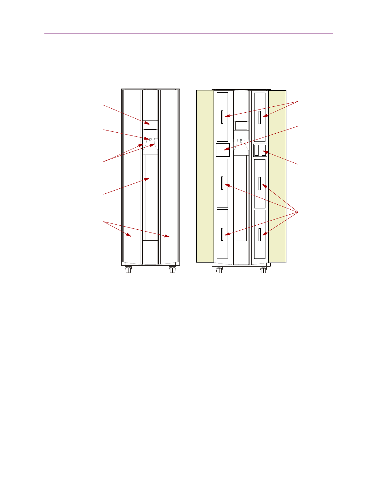
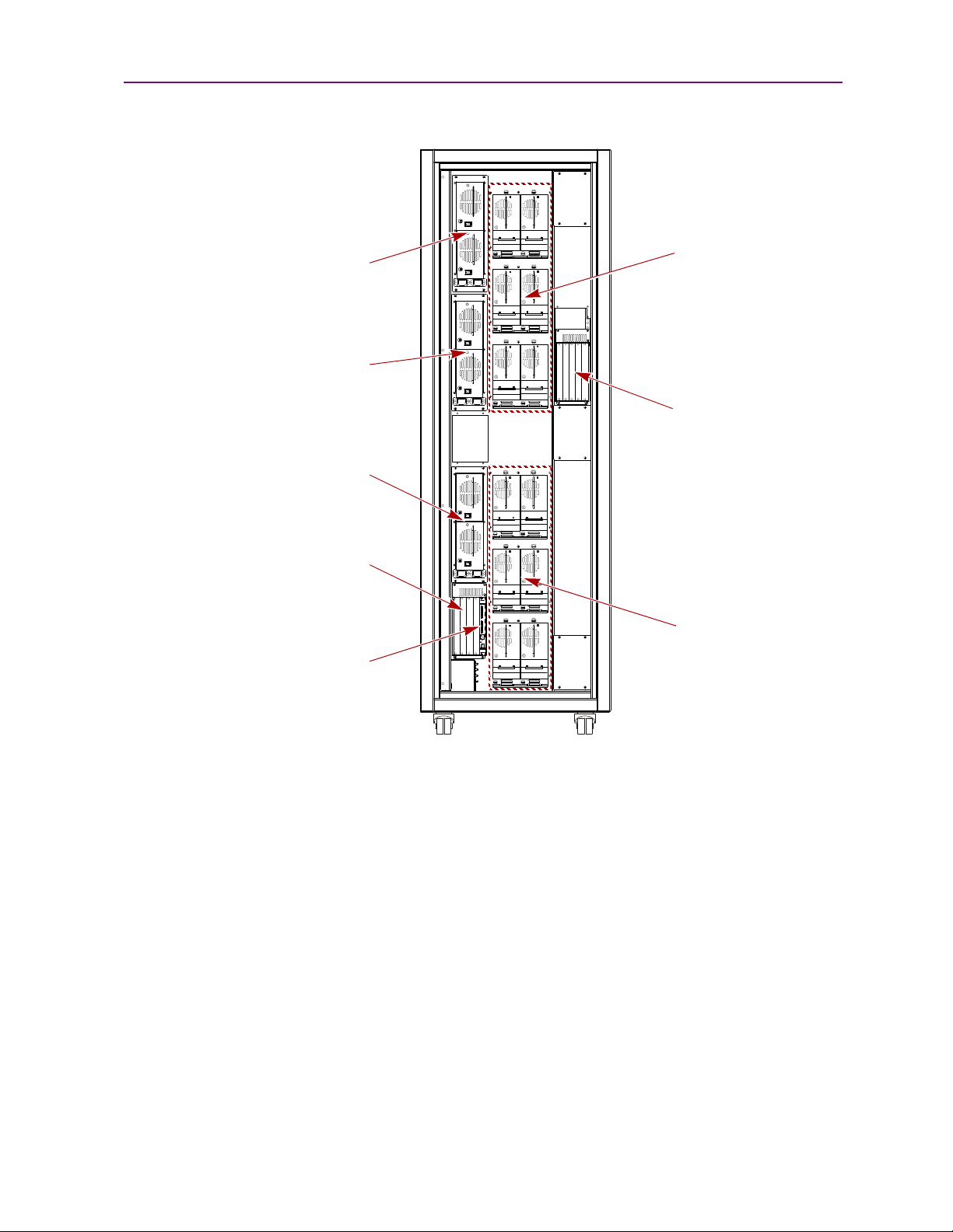
Front Components
The library is designed to allow easy access to the control panel and tapes from the front
(Figure 1-1).
GUI Touch Screen
The Graphical User Interface (GUI) touch screen on the front of the NEO 8000 provides an
easy way to directly communicate with the library. By gently pressing the virtual buttons,
you can select menus and options to change library settings.
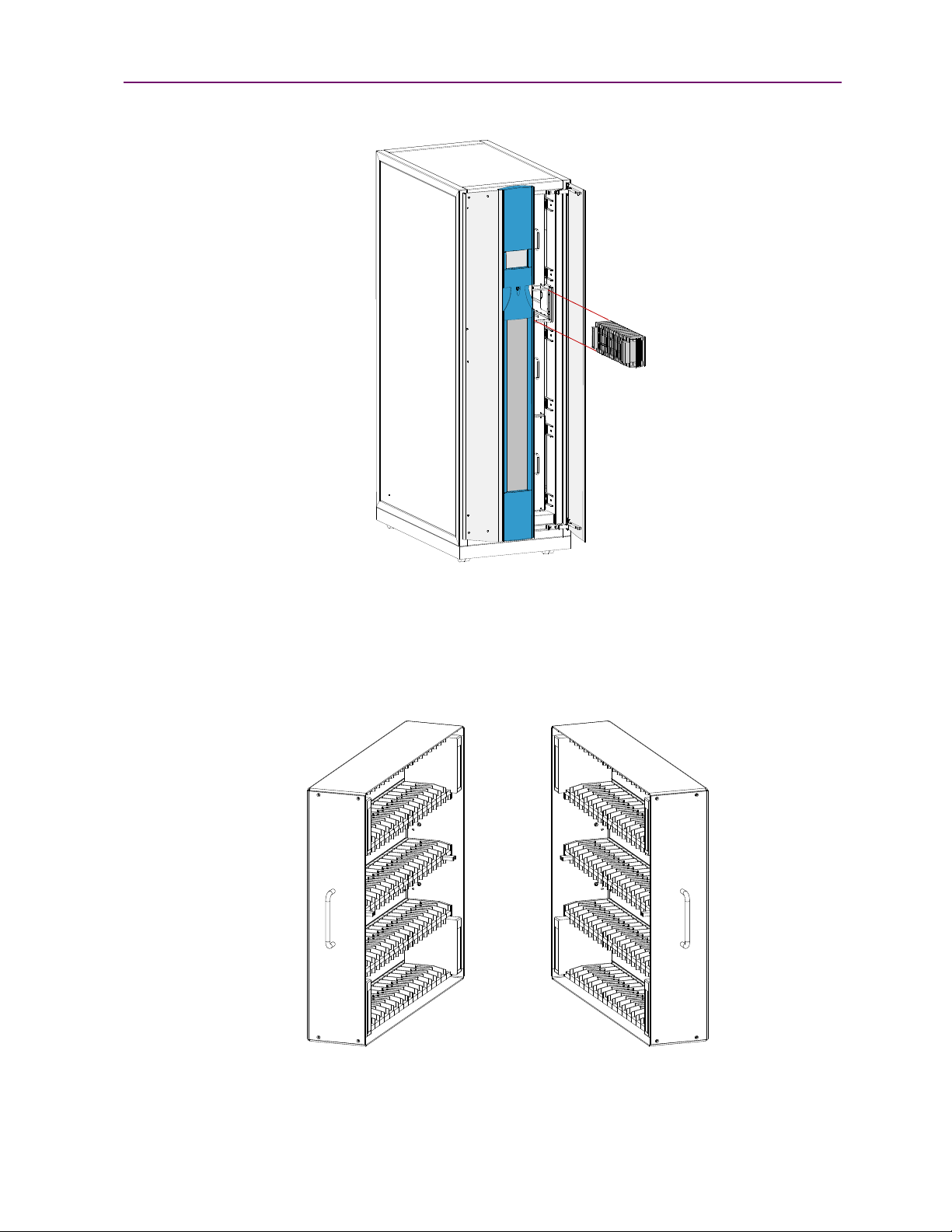
Mail Slot Magazine
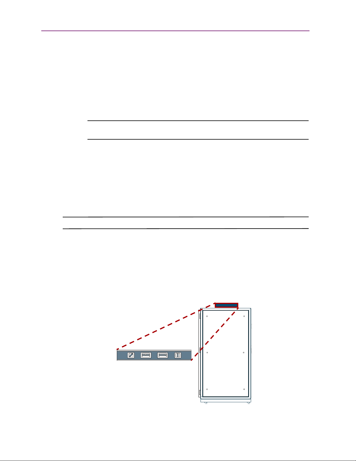
The NEO 8000 has one removable import/export tape cartridge magazine, called a Mail Slot,
that is accessible through the right front door (Figure 1-2). The Mail Slot holds up to 15 LTO
cartridges. It provides an easy method for adding or removing cartridges without having to
stop the library to open drawers.
1–2 X 10400267-101 09/2009
Figure 1-1: NEO 8000 Front View
Page 11
Library Design and Layout
N
E
O
-
8
0
0
8
N
E
O
-
8
0
1
1
N
E
O
-
8
0
3
0
Figure 1-2: Mail Slot Location
Media Drawers and Fixed Slots
There are six media drawers (Figure 1-3) in the NEO 8000 Library. Each drawer holds up to
80 LTO cartridges.
Figure 1-3: NEO 8000 Left and Right Media Drawers
10400267-101 09/2009 W 1–3
Page 12
Chapter 1: NEO 8000 Library Overview
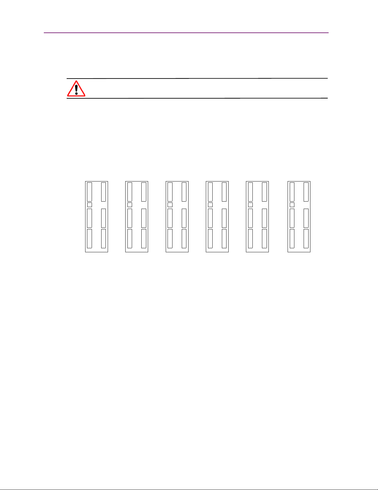
112
12 12 1212
34 34 343
556
1 Drawer 2 Drawers 3 Drawers 4 Drawers 5 Drawers All Enabled
For security and safety, the drawers are internally latched to prevent unauthorized access.
With the proper security credentials, they can be released from the GUI touch screen on the
front of the library.
WARNING: Removing the media drawers from the library units is not recommended
except by Authorized Overland Service Technicians.
Between the left side top and middle drawers, directly across from the Mail Slot, is a row of
fixed slots that can only be accessed by the internal robotics. These slots hold up to 20 LTO
cartridges. They can be accessed using Menu > Maintenance > Load/Unload Fixed Slots
commands. They can also be reserved for cleaning cartridges using Menu > Library > Total
Reserved Slots.
The NEO 8000 comes with 1-6 drawers enabled, depending on the purchased configuration.
Any disabled drawers can be activated by purchasing additional capacity and entering the
upgrade code (Figure 1-4).
NOTE: The fixed slots on the left side between the top and middle drawers are always enabled
and listed after any enabled drawers. For example, in an LTO library with four enabled
drawers (Slots 1–320), the fixed slots are numbered 321 to 340.
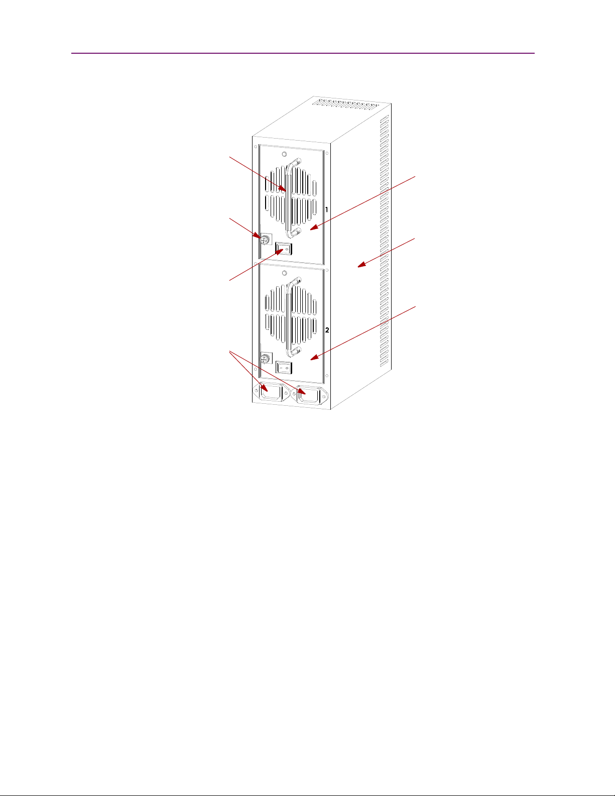
Rear Components
The rear of the library (Figure 1-5) provides easy access to the operational hardware. The
basic unit has 2 drives, 4 power supplies (for the lower drives and robotics, both primary and
redundant), and a Library Controller card. There is a power supply case for the optional
power supplies required for drives 7–12. Two V.I.A. card cages are available for the Library
Controller card and nine optional V.I.A. expansion cards.
Figure 1-4: Media Drawer Activation Order
1–4 X 10400267-101 09/2009
Page 13
Library Design and Layout
N
E
O
-
8
1
1
9
Primary
Secondary
Drives 7-12
Card Cage
Power Supplies
Library
Drives 1-6
For Robotics
Card Cage
Controller
Card (Req’d)
Power Supplies
For Drives 1-6
Power Supplies
For Drives 7-12
Figure 1-5: NEO 8000 Rear View
Power Supplies
Power is routed via power cords through the base plate of the unit into connectors on the
circuit breaker box at the base of the built-in power strip. The power strip contains
geographically placed receptacles which make AC power available to the power supply cases
without the need for routing cables.
Each power supply case holds two power supplies (Figure 1-6). The upper power unit is the
primary power source while the lower unit is the redundant power source.
10400267-101 09/2009 W 1–5
Page 14
Chapter 1: NEO 8000 Library Overview
N
E
O
-
8
0
2
2
a
Primary
Redundant
Power
Supply (#1)
Power
Supply (#2)
Foldable
Handle
Thumbscrew
Release
ON/OFF
Switch
Power
Inputs
(from bus)
Power
Supply
Case
The NEO SERIES 8000 Library has three power supply cases that distribute AC power to
different portions of the library. Each power supply case holds two modular auto-ranging
power supplies: a primary power supply for daily use and a secondary power supply for
redundancy.
Each power supply is capable of using any nominal AC voltage between 100 and 240 Vac
power, at 50 Hz or 60 Hz. A thumbscrew release secures each power supply in it’s respective
power supply case.
For the library to operate, power must be available to the library controller card, robotics,
and all installed drives. Therefore, two power supplies must be installed in the middle
Robotics power supply case and two power supplies must be installed in the lower Drives 1-6
power supply case. If more than 6 drives are installed, two power supplies must also be
installed in the upper Drives 7-12 power supply case.
Power Redundancy
Power supply cases must contain two power supplies to provide redundancy for mission
critical operations and avoid power interruption to the library. Power supplies share the
load under normal operating conditions. However, if one of the power supplies fails, the
other will assume the full load.
1–6 X 10400267-101 09/2009
Figure 1-6: Power Supplies in a Power Supply Case
Page 15
Library Design and Layout
N
E
O
-
8
0
1
4
b
ONOFF
AC
Receptacles
Circuit 1
Circuit 2
(Primary)
(Secondary)
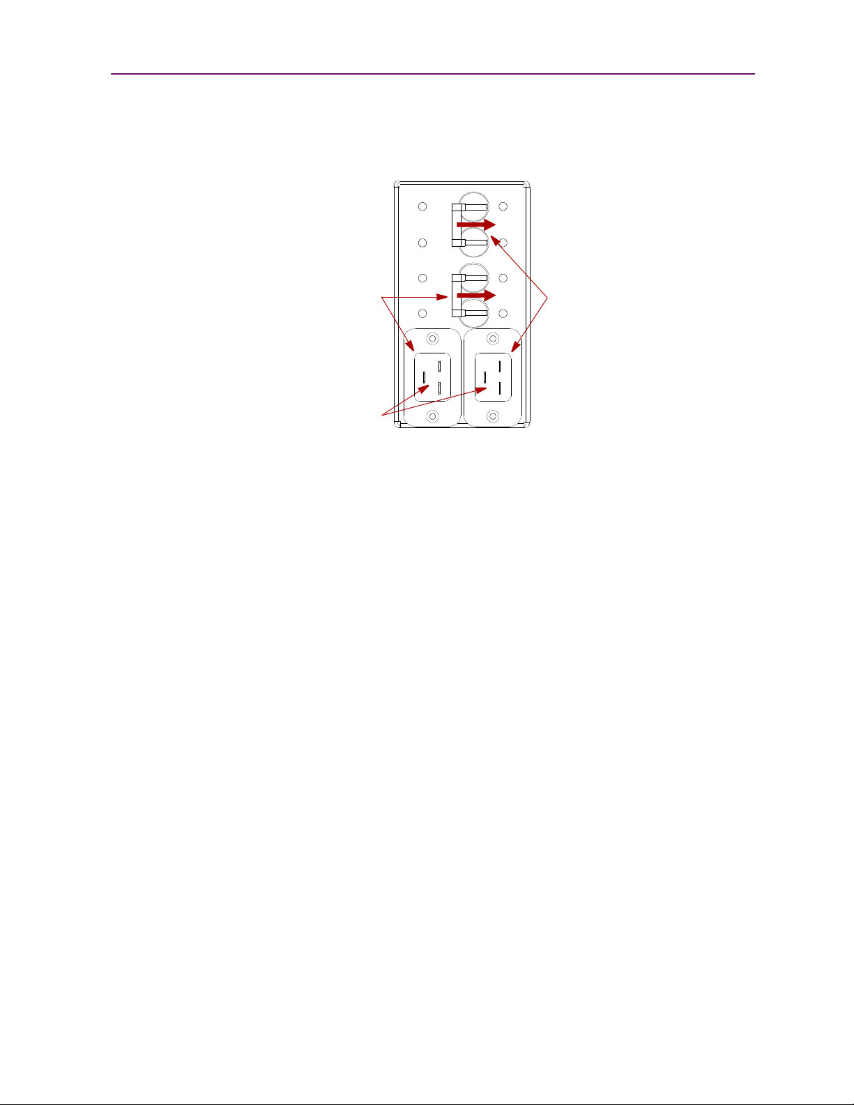
Power Circuits
NEO 8000 has two power circuits to support the power redundancy option (Figure 1-7).
Figure 1-7: NEO 8000 Circuit Breakers Showing Primary and Secondary Circuits
The Primary circuit consists of the right-hand receptacle and top breaker on the circuit
breaker box, the upper receptacles of the power strip, and the upper installed power
supplies. The power strip receptacles and power supply cases are labeled with a “1.” The
Secondary circuit is the left-hand receptacle and lower breaker on the breaker box, the lower
receptacles of the power strip, and the lower installed power supplies. The power strip
receptacles and power supply cases are labeled with a “2.”
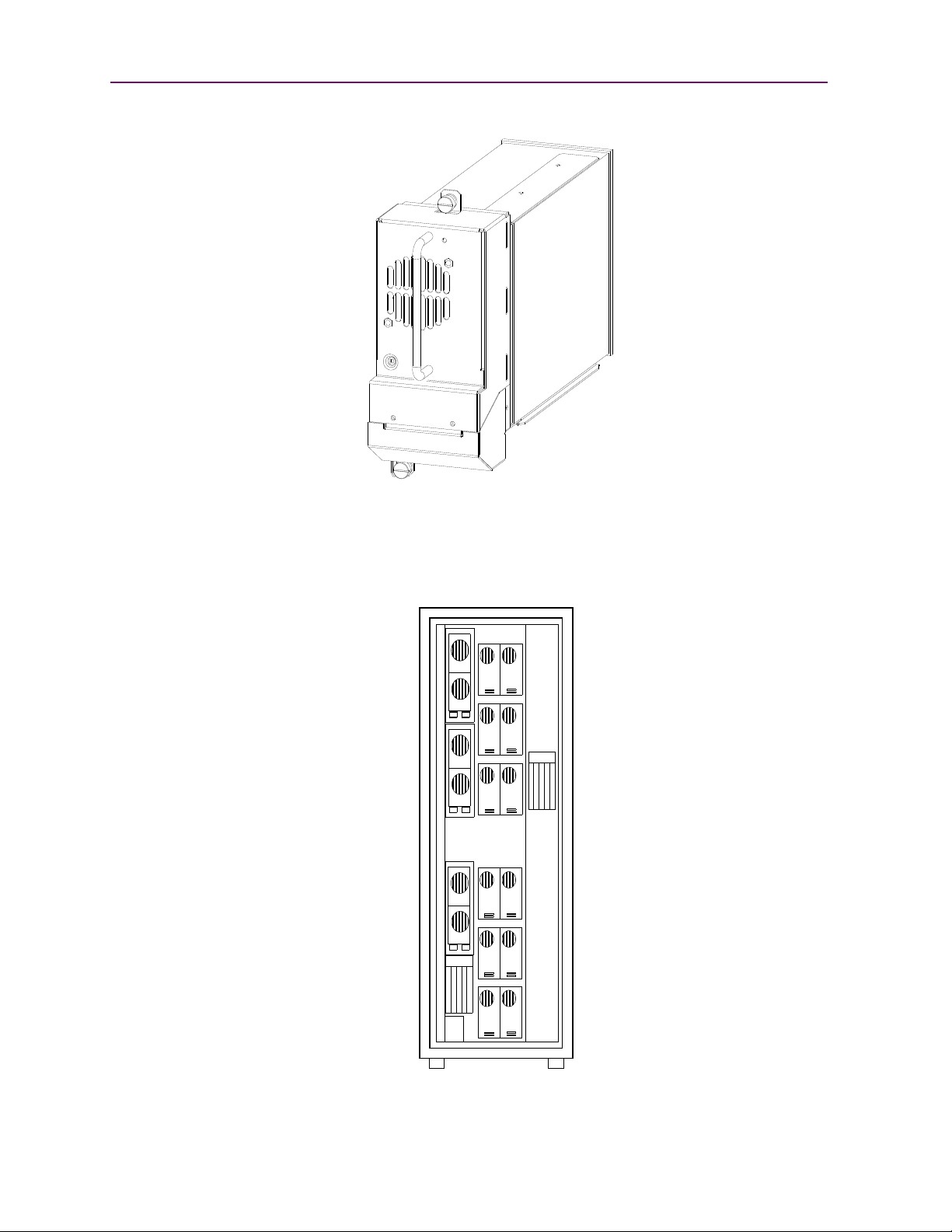
Drive Assemblies
The NEO 8000 library supports 2-12 tape drives (Figure 1-8). The tape drives are mounted
on special assemblies to make them hot-swap capable and provide non-disruptive
replacement.
10400267-101 09/2009 W 1–7
Page 16
Chapter 1: NEO 8000 Library Overview
N
E
O
-
8
0
6
8
12
34
56
78
910
1112
Figure 1-8: NEO 8000 Drive Assembly (SCSI)
The NEO 8000 base configurations have either zero or two drives. Additional drives can be
added one at a time, as needed, until the library is fully populated with 12 drives
(Figure 1-9).
1–8 X 10400267-101 09/2009
Figure 1-9: NEO 8000 Drive Numbering
Page 17

Library Design and Layout
The SCSI I/O for the tape drives is provided through VHDCI, 68-pin, SCSI connectors
located at the rear of the unit directly under the drives. The Fibre Channel I/O is managed
through connections located on the upper-right of Fibre Channel drives.
CAUTION: When using Fibre Channel cabling, the SCSI connectors should not be used.
Library Interfaces
The NEO 8000 features a Low Voltage Differential (LVD) SCSI interface-to-host system.
Other interfaces, such as HVD SCSI or Fibre Channel, are available with optional V.I.A.
cards. Separate SCSI connections and ID addresses are used to control the functions of the
tape drives and robotics.
Virtual Interface Architecture
The NEO 8000 contains two rear-access card cages and a Compact PCI backplane. This
backplane contains the plug-in connectors for the library’s controller board and up to nine
V.I.A. PCI cards.
The V.I.A. cards provide an easy way for the network or SAN to communicate with the
library. Simple to exchange, they offer upgrade flexibility to expand the life of the library.
Currently available cards include:
• Fibre Channel Option—provides connectivity to Fibre-based SANs.
• Gigabit Ethernet Option—provides connectivity to iSCSI Gigabit Ethernet Networks.
• High Voltage Option—provides connectivity to High Voltage Differential SCSI
systems.
• Internal Router—offers a WebTLC interface when in a Master/Slave configuration.
• Library Partition Option—provides logical soft partitioning to the drawer level
between heterogeneous servers and backup software applications.
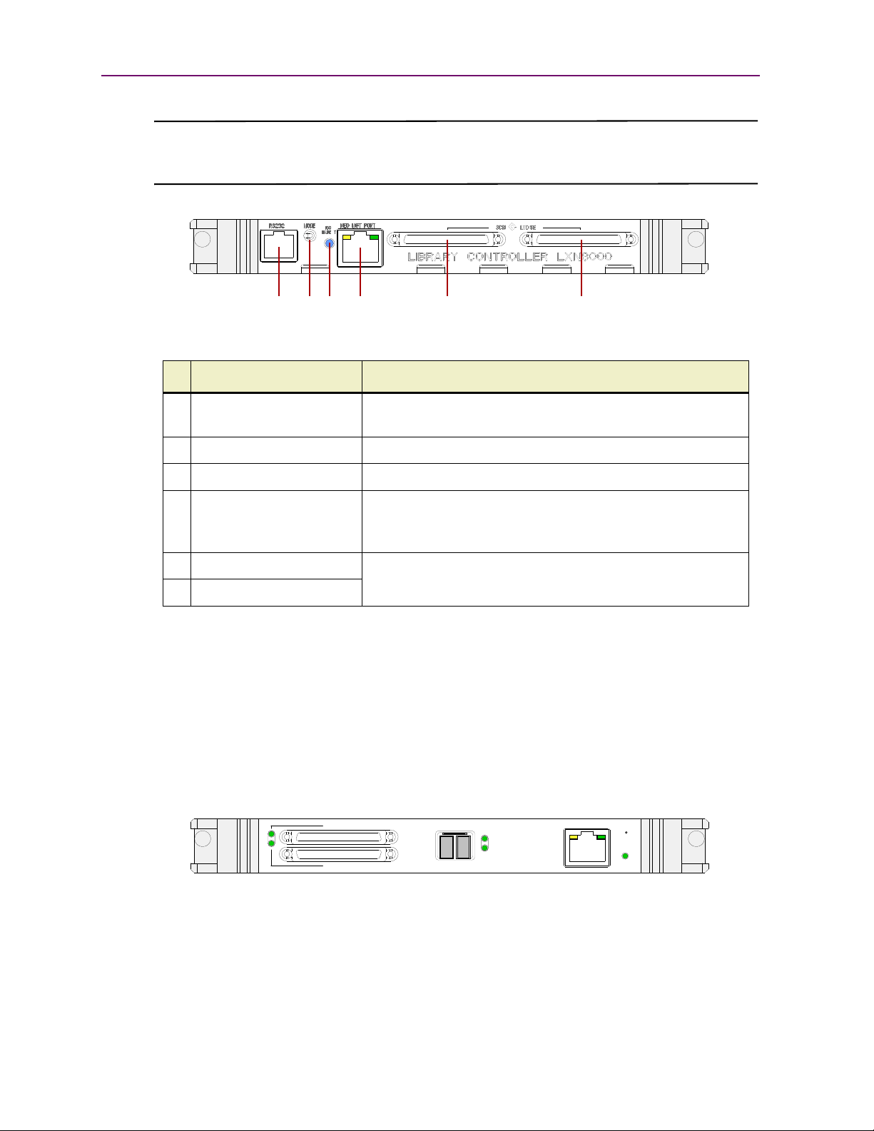
Library Controller Card
The Library Controller card (Figure 1-10) contains a single microprocessor and associated
logic devices to control all robotics operations and manage overall library functions. The
microprocessor enables the SCSI interface between the library and the host system,
including WebTLC (Web-based Total Library Control).
WebTLC is one of the functions built in to the Library Controller card. WebTLC enables you
to remotely monitor and control the tape library from any terminal in a local network or the
internet.
The SCSI I/O for the robotics is provided through VHDCI, 68-pin, SCSI connectors located
on the Library Controller card. The card also contains a sensor for control of the backplane
fans to prevent overheating.
The Library Controller card is installed in the lower card cage at the rear of the library, and
can be serviced without requiring special tools.
10400267-101 09/2009 W 1–9
Page 18
Chapter 1: NEO 8000 Library Overview
N
E
O
-
8
0
7
6
b
1234 5 6
V
I
A
-
0
0
7
8
Fibre ChannelSCSI Port 1
SCSI Port 2
Link
Activity
Ethernet
Ready
Fault
Reset
CAUTION: The Library Controller card must be installed in the right slot of the lower card cage. The
upper card cage does not support the required connections for proper operation of the Library
Controller board.
Figure 1-10: NEO 8000 Library Controller Card
# Port Description Function
1 RS-232 Serial Port RJ-11 based RS-232 serial port for firmware updates and
2 Mode Momentary Switch For service use only.
local configuration and management.
3 Power LED Glows blue when power is available.
4 Ethernet Port RJ-45 GigE Ethernet Port for connecting to your management
LAN for either local or out-of-band remote configuration and
management (such as WebTLC).
5 SCSI Port 0 VHDCI-based LVD SCSI Ports for connecting to the NEO
6SCSI Port 1
SERIES library and tape drives.
Fibre Channel Option Card
The V.I.A. Fibre Channel Option (FCO3) card (Figure 1-11) is a 4/2/1-Gigabit Fibre
Channel-to-SCSI bridge configured with one Fibre Channel port and two independent SCSI
buses (1x2) providing an interface between SCSI and Fibre Channel resources in a Storage
Area Network (SAN). It includes battery backed-up memory, verbose trace log capabilities,
and date/time stamp.
The FCO card is designed to fit into either one of the V.I.A. bays built into the NEO 8000.
Refer to the documentation that accompanies the card for more details.
Figure 1-11: FCO3 Card
1–10 X 10400267-101 09/2009
Page 19
Library Design and Layout
V
I
A
-
0
0
4
9
b
SCSI Port 0
SCSI Port 1
Data Port 0
RS-232
Fault
G
b
E
O
p
t
i
o
n
C
a
r
d
Data Port 1 Management Port
N
E
O
-
8
0
7
6
b
Gigabit Ethernet Option Cards
The V.I.A. Gigabit Ethernet Option (GEO) card (Figure 1-12) is a Gigabit Ethernet-to-SCSI
bridge for the NEO SERIES libraries. The GEOi card supports both the copper version of the
Gigabit Ethernet (GigE) standard of 1000 Base-T, and Revision 2.0 of the Internet
Engineering Task Force (IETF) iSCSI protocols
.
The GEO card allows NEO SERIES libraries to communicate seamlessly with GigE
networks providing protocol conversion for iSCSI commands, routing commands, data, and
status information between SCSI devices and an iSCSI SAN.
The GEO card is designed to fit into either one of the V.I.A. bays built into the NEO 8000.
Refer to the documentation that accompanies the card for more details.
Figure 1-12: GEOi Card
High Voltage Option Card
The V.I.A. High Voltage Option (HVO) card (Figure 1-13) provides a bridge for the NEO
8000 to work seamlessly with existing High Voltage Differential SCSI-based servers and
systems. With an 80 MB/sec maximum transfer rate, the HVO card meets the performance
demands of even the fastest HVD SCSI systems. The card supports all major operating
systems including HP-UX, IBM AIX, Linux, Mac OS, Novell NetWare, SCO UNIX, Sun
Solaris, Tru64 UNIX, and Windows NT/2000.
The HVO card is designed to fit into either one of the V.I.A. bays built into the NEO 8000.
Refer to the documentation that accompanies the card for more details.
Figure 1-13: HVO Card
10400267-101 09/2009 W 1–11
Page 20
Chapter 1: NEO 8000 Library Overview
V
I
A
-
0
0
7
3
b
12345678
V
I
A
-
0
0
5
3
b
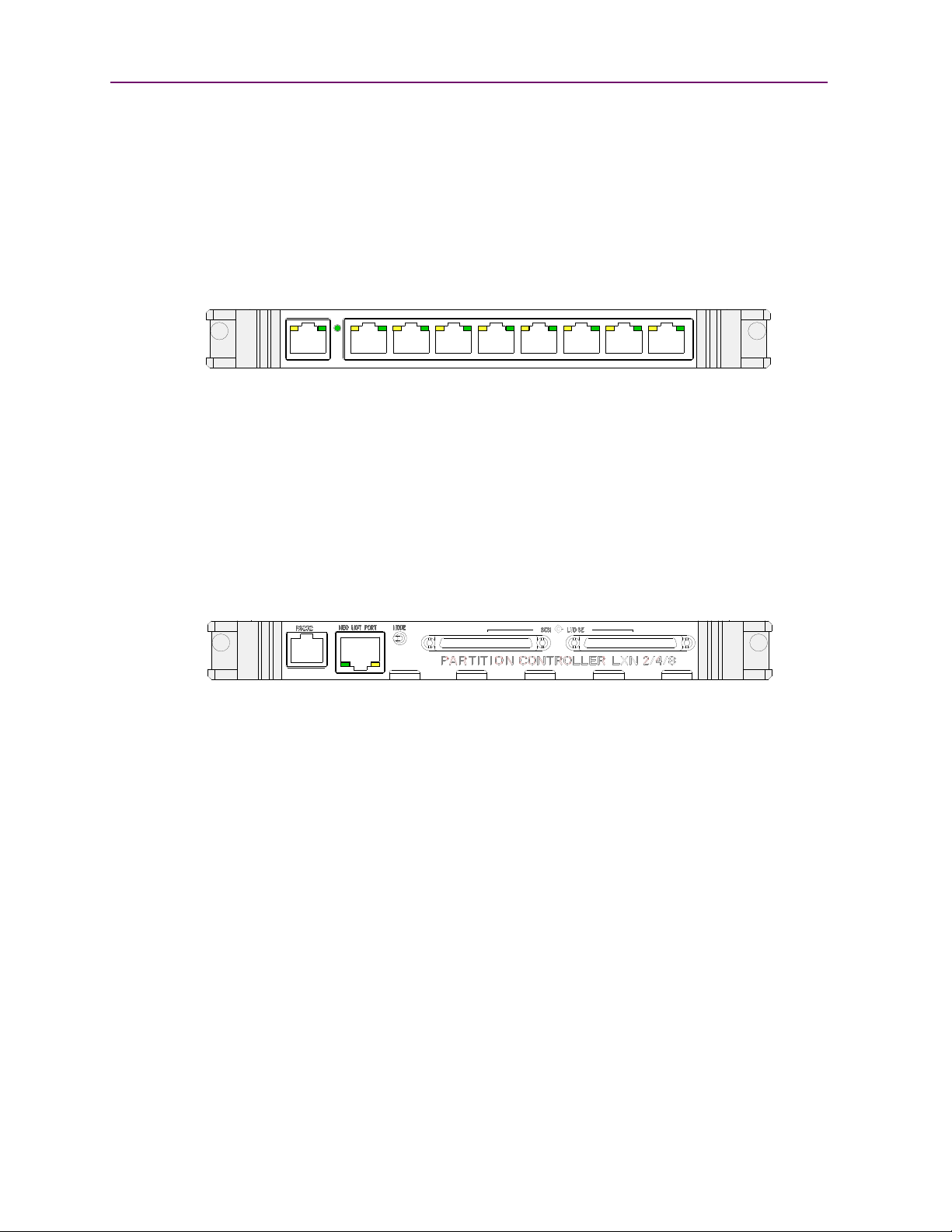
Internal Router Card
The V.I.A. Router card (Figure 1-14) is a special purpose device designed with one specific
function—to provide a WebTLC interface for the NEO 8000 when in a Master/Slave
configuration (i.e., partitioned or multi-module). To the external network, it functions as an
endpoint device, not a network router or switch.
The Router card must be installed in one of the lower option card slots of the NEO 8000.
Refer to the documentation that accompanies the card for more details.
Library Partitioning Controller Card
The V.I.A. Partition Controller card (Figure 1-15) allows multiple servers to use the same
physical library while maintaining control of their allocated resources. Each controller card
can be connected directly to the SCSI bus of a server or daisy-chained to another SCSI bus.
Figure 1-14: Router Card
LPO cards can be installed in either the upper or lower card slots based on which slots are
most convenient for cabling the SCSI bus. Refer to the documentation that accompanies the
card for more details.
Figure 1-15: LPO Card
1–12 X 10400267-101 09/2009
Page 21

Capacity Configurations
N
E
O
-
8
1
1
9
N
E
O
-
8
1
0
5
Basic Configuration Fully Populated Configuration
Upper
Power
Case
Drives 7-12
Drives 1-6 are powered by the lower power supplies that come standard on the NEO 8000.
When expanding to drives 7-12, additional optional power supplies need to be installed in
the upper power case (Figure 1-16).
Library Design and Layout
Figure 1-16: NEO 8000 Rear Views: Basic and Fully Populated
10400267-101 09/2009 W 1–13
Page 22

Chapter 1: NEO 8000 Library Overview
1–14 X 10400267-101 09/2009
Page 23
2
CHAPTER
Unpacking and Setting Up
IMPORTANT: Overland Storage recommends that all NEO 8000 Libraries be installed by an
Overland Storage authorized service provider.
This chapter describes how to unpack and set up a new NEO 8000 Library. This same
information is also available in the NEO 8000 Library Important Unpacking Instructions
located on the outside of the shipping container.
WARNING: Exercise care when unpacking and moving the NEO 8000 Library. Due to
its size and weight, it is recommended that at least two people be involved with the
unpacking process.
CAUTION: You should read and familiarize yourself with this entire chapter before starting the
unpacking procedure. Steps performed out of sequence may cause damage to the library which
voids existing warranties.
NOTE: Retain all packaging materials in a protected place in case the library needs to be
shipped to a different location.
Tools Needed
These tools that are needed to unpack the library:
• 9/16” wrench
• 10” adjustable wrench
• Large flat-blade offset screwdriver
• Box knife
Removing the Outer Carton
To ensure safe delivery, each NEO 8000 comes packed with tie-down hardware securing it
to the pallet. The proper steps must be taken to remove the packaging.
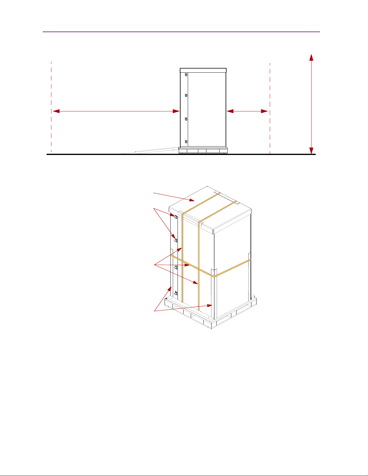
1. Position the shipping container on a level surface so there is enough clearance to
work around it (Figure 2-1).
• Allow at least 10 feet of clear space on the removal side of the container.
• Allow about 3 feet of clearance around the other three sides of the container.
• At least 8 feet of vertical clearance is needed.
NOTE: The container pallet is labeled “RAMP SIDE” on each corner of the removal side.
10400267-101 09/2009 W 2–1
Page 24
Chapter 2: Unpacking and Setting Up
N
E
O
-
8
1
1
7
`
Allow at least 10 ft. in
the rear to remove the
library from the pallet
Ramp
Floor
Allow 3 ft.
around
the library
Allow 8 ft.
vertical
clearance
N
E
O
-
8
1
1
3
Plastic
Strap
Corners
Reinforcing
Shipping
Retainers
Straps
Top Cap
Figure 2-1. Unpacking Space Requirements
2. Remove the outside packaging (Figure 2-2).
a. Cut the three (3) shipping straps and remove.
b. Remove the six (6) shipping strap reinforcing corners from around the box.
c. Remove the top cap.
d. Release and remove each of the eight (8) plastic retainers (four each on opposite
corners).
e. Remove the two (2) large pieces of cardboard surrounding the library.
2–2 X 10400267-101 09/2009
Figure 2-2: Library Packaging Components
Page 25
3. Remove the inner packaging (Figure 2-3).
N
E
O
-
8
1
1
4
RAMP Box
Strap
(Library hidden for clarity)
Front
Top Pads
DOOR Box
N
E
O
-
8
1
1
5
(Library hidden for clarity)
Slots
Ramps
Detaching the Pallet
Figure 2-3: RAMP and DOOR Box Locations
a. Remove the two (2) pads on top of the library.
b. While holding the RAMP and DOOR boxes (one on each side of the library), cut and
remove the strap that secures the boxes to the library.
c. Remove the RAMP and DOOR boxes and set them aside for now.
d. Remove the plastic sheet that covers the library.
Detaching the Pallet
Once the cardboard pieces are removed, you can remove the hold-down hardware.
1. Remove the ramps from the RAMP box and lay them down, placing the brackets into
the corresponding slots in the pallet (Figure 2-4).
Figure 2-4: Placing the Ramps in Position
10400267-101 09/2009 W 2–3
Page 26
Chapter 2: Unpacking and Setting Up
N
E
O
-
8
1
1
6
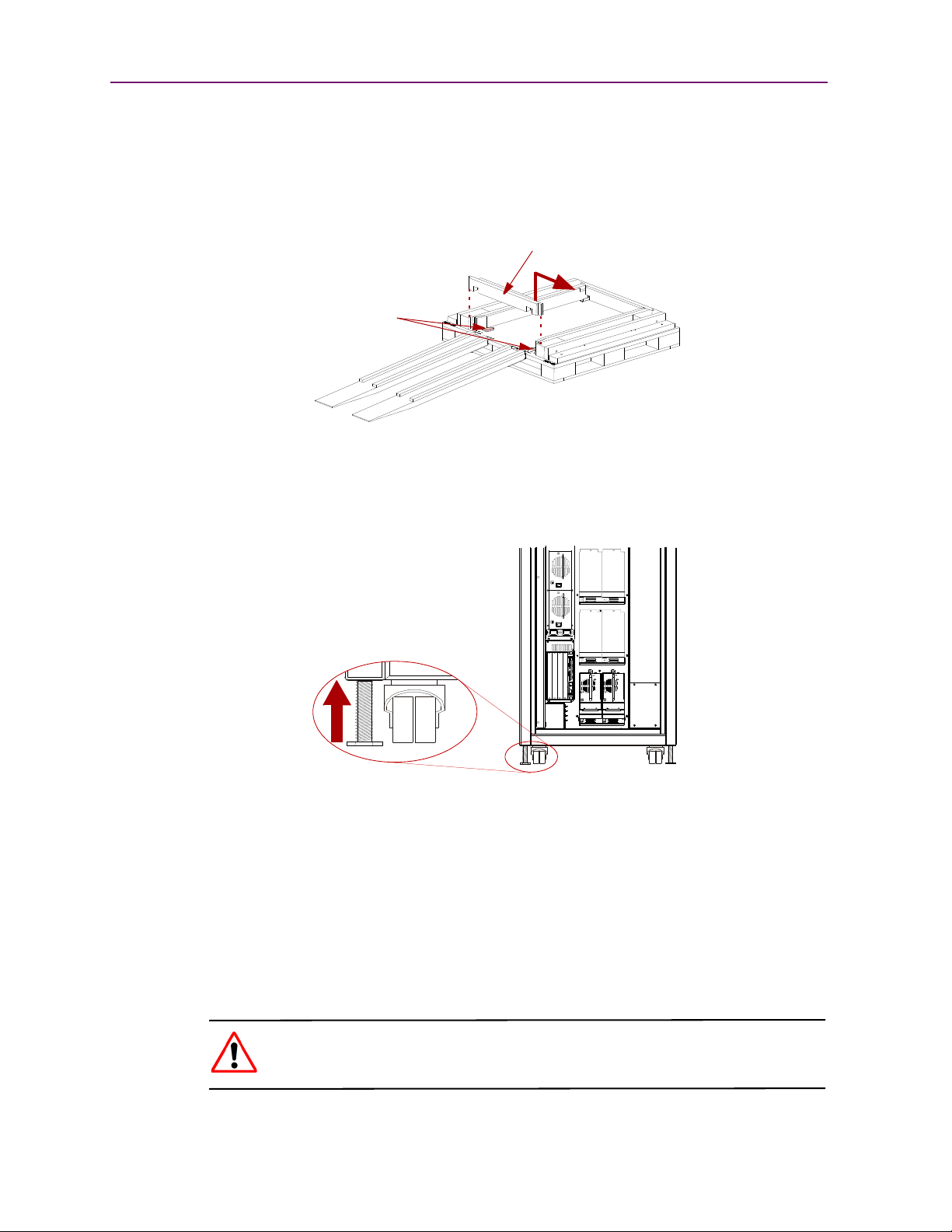
Crossbar
Bolts
(Library hidden for clarity)
N
E
O
-
8
1
0
6
2. Remove the rear hardware holding the library on the pallet.
a. To provide access to the hold-down bolts and leveling legs, remove the rear
crosspiece (Figure 2-5). This is done by opening the rear door, lifting the right
end of the crosspiece, and sliding the left end of the crosspiece out of its recess.
Figure 2-5: Removing the Rear Crosspiece
b. Use a 9/16” wrench to remove the two bolts and hold-down brackets.
c. Use the adjustable wrench to loosen and raise the two leveling legs (Figure 2-6).
3. Remove the front hardware holding the library on the pallet.
NOTE: Lift the front crosspiece ends for access to the bolts, brackets, and leveling legs.
a. Use a 9/16” wrench to remove the bolts and hold-down brackets.
b. Use the adjustable wrench to loosen and raise the two leveling legs
(Figure 2-6).
4. Verify that all four leveling legs can clear the floor at the bottom of the ramp and that
the library is only supported by the four caster wheels.
2–4 X 10400267-101 09/2009
Figure 2-6: NEO 8000 Casters and Leveling Legs
WARNING: Most of the weight of a library is in the rear of the unit. If the leveling
legs are not raised high enough, they can catch at the bottom of the ramps, tipping
over the library unit.
Page 27
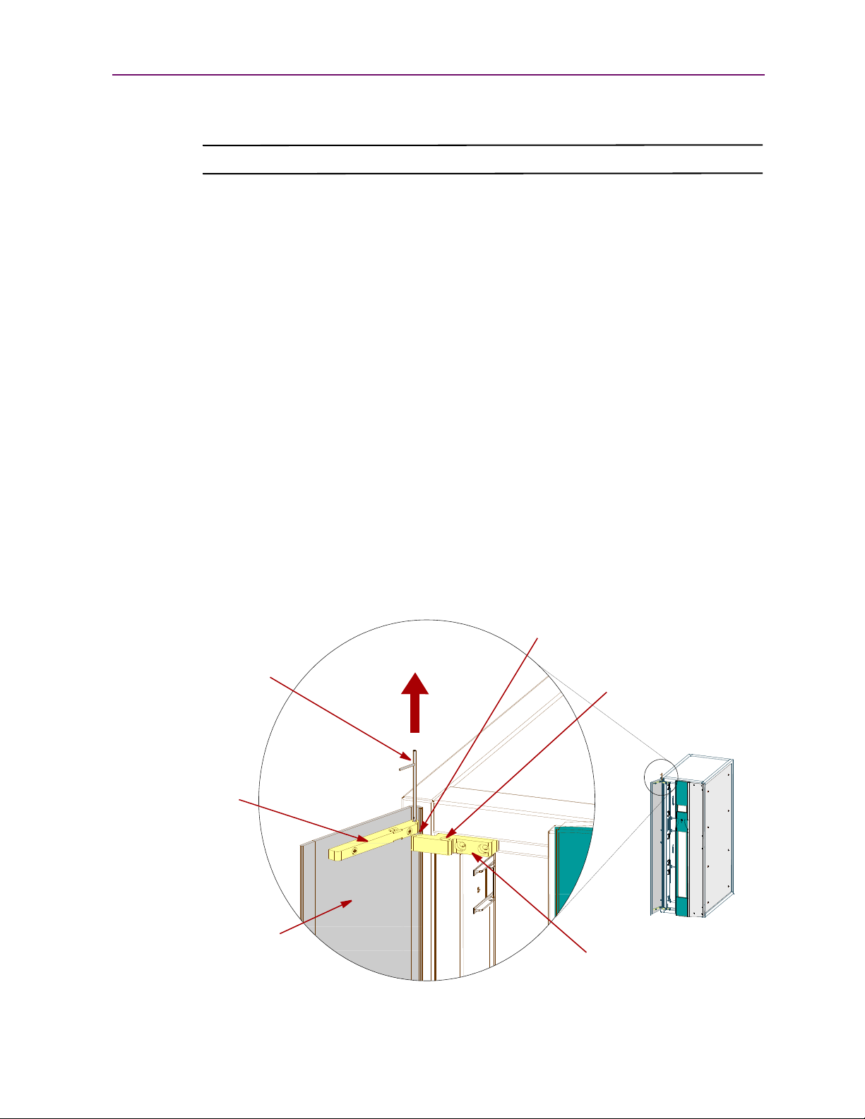
5. Carefully move the library down the ramps and onto the floor.
N
E
O
-
8
0
9
1
Nylon Washers
Door
Left Door
Hinge
Block
Library Hinge Block
(between hinges)
Hinge Pin
Door Check
CAUTION: Do not pull on the media drawer handles when moving the library.
Attaching the Front Doors
Before moving the library to its final operating position, attach the front doors.
NOTE: The square, straight end of the door is the top and the curved end is the bottom.
1. Remove the two doors from the DOOR shipping box and extract them from their
plastic shipping bags.
2. Locate the bag of nylon washers inside the bag on the back door.
The washers are used as bearings between the hinges.
3. Attach the left door and adjust it for alignment and operation (Figure 2-7).
a. Lift the top hinge pin just enough to retract the tip into the left door’s hinge
block.
Attaching the Front Doors
b. Place one nylon washer onto the bottom hinge pin that protrudes below the door
hinge block.
It is held in place by the hinge pin’s ball retainer.
c. Position the door vertically with the bottom hinge pin above the library hinge
block hole and seat it.
d. Raise the door slightly, push down the top hinge, and place a washer on it.
Figure 2-7: Attaching the Doors
10400267-101 09/2009 W 2–5
Page 28
Chapter 2: Unpacking and Setting Up
N
E
O
-
8
1
1
2
e. Lower the door so that the top hinge pin is above the library hinge block hole and
seat it.
f. Using the flat-blade offset screwdriver, unscrew the door checks in both the
upper and lower library hinge blocks until the door closes freely.
g. Close the door and check that the top edge of the door meets the front panel
façade evenly.
• If the door is low, add washers to raise the door.
• If the door is high, remove the top washer.
CAUTION: The weight of the door should be carried by at least one hinge with a nylon
washer.
h. When the door height is correct, screw in the door checks until the door closes
smoothly yet is held firmly.
4. Repeat Steps a–h for the right door.
Leveling the Library
You are now ready to move the unit into its final position and level it.
CAUTION: Do not pull on the media drawer handles when moving the library.
1. Position the library at its operating location.
2. Run down all four leveling legs by hand until they contact the floor.
3. Using a wrench, turn each leg, one after the other in equal increments, until you have
turned them at least one full turn.
NOTE: Be sure the library has been raised high enough so none of the casters touch the floor.
4. Place a level, front to rear, on the top side edge of the library (Figure 2-8).
2–6 X 10400267-101 09/2009
Figure 2-8: Positioning the Level
Page 29
5. Note the position of the bubble. Raise both of the front legs or both of the rear legs the
N
E
O
-
8
0
0
6
Right-side
Brackets
same amount to achieve a level front-to-rear reading.
6. Place the level across the top front edge of the library.
7. Note the position of the bubble. Raise both of the left feet or both of the right feet the
same amount to achieve a level side-to-side reading.
8. Recheck the level from front-to-rear and from side-to-side. Adjust as needed until the
library is level.
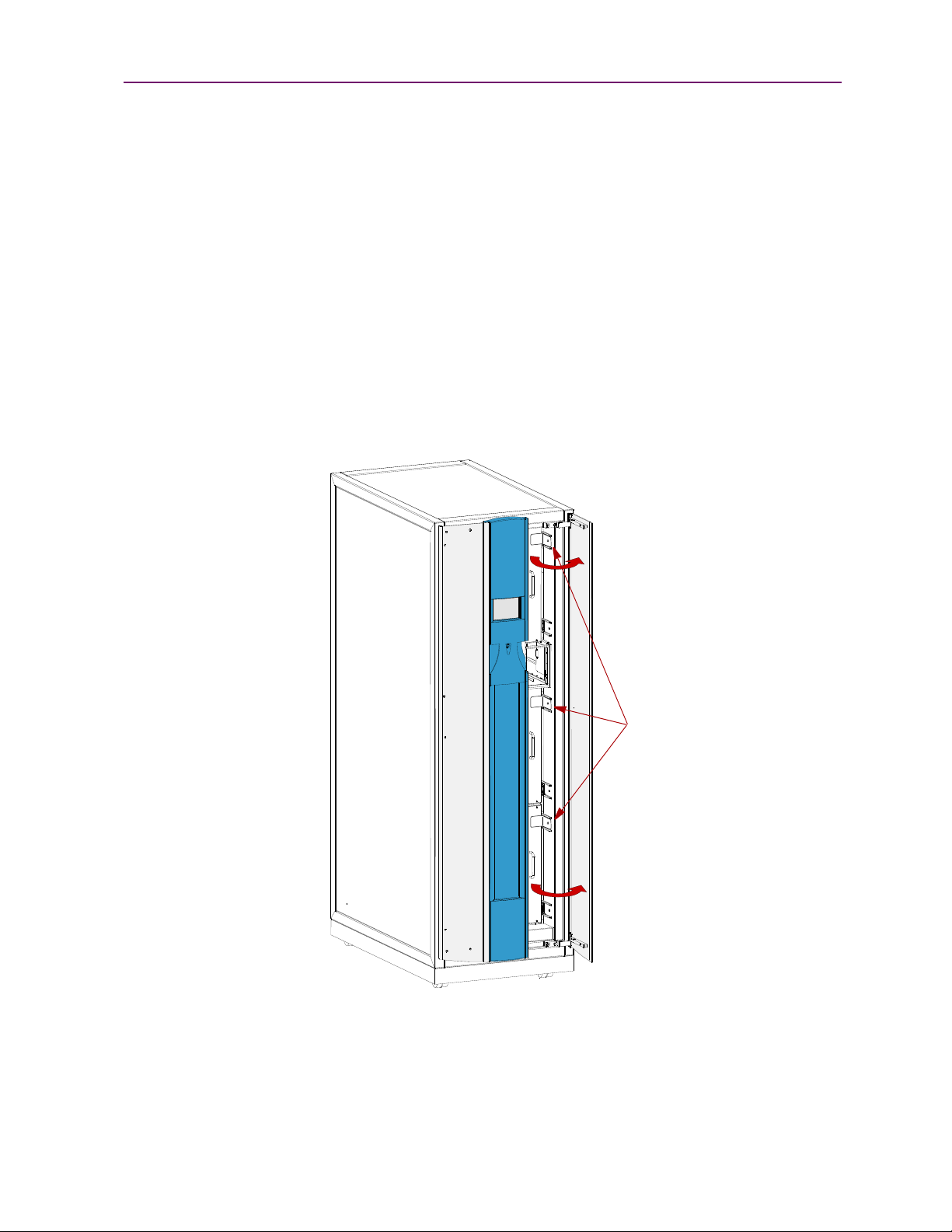
Remove the Drawer Shipping Brackets
Once the library is in position, use a phillips screwdriver to remove the six drawer shipping
brackets located inside the doors on the side trim pieces (Figure 2-9). Replace the screws
back into the trim pieces and retain the brackets.
Remove the Drawer Shipping Brackets
Figure 2-9: Drawer Shipping Brackets
10400267-101 09/2009 W 2–7
Page 30

Chapter 2: Unpacking and Setting Up
2–8 X 10400267-101 09/2009
Page 31

Installation and Initialization
3
CHAPTER
Once the NEO 8000 Library is secure and level, you need verify the basic cable
connections are in place before powering on the library for the first time.
Installation Considerations
If the unit is installed in a closed environment it may require further evaluation by
Certification Agencies. The following items must be considered:
• The ambient temperature within the unit may be greater than room ambient.
Installation should be such that the amount of air flow required for safe operation is
not compromised. The maximum temperature for equipment environment is 50°C.
Consideration should be given to maximum rated ambient.
• Installation should be such that a hazardous stability condition is not achieved due
to uneven loading.
Input Supply
Check nameplate ratings to assure there is no overloading of supply circuits that could
have an effect on over-current protection and supply wiring.
Grounding
Reliable earthing of this equipment must be maintained. Particular attention should be
given to supply connections when connecting power strips, rather than direct connections
to the branch circuit.
Power-Up and Cabling Pre-Check
The NEO 8000 comes from the factory with any installed components connected and
ready to use. Before powering up the library, it is recommended that you verify these
connections have not come loose in shipment.
NEO 8000 Libraries come with zero factory-installed drives. All drives are shipped as
“add-on” drives and must be installed on site. Refer to the instructions that come with
every add-on drive assembly for the preferred installation procedure and cabling
recommendations.
For more information about cabling options, refer to Chapter 8, “Cabling Options and
Examples.”
10400267-101 09/2009 W 3–1
Page 32

Chapter 3: Installation and Initialization
N
E
O
-
8
0
1
4
b
ONOFF
AC
Receptacles
Circuit 1
Circuit 2
(Primary)
(Secondary)
Powering Up the Library
Use the following instructions to apply power to your library:
1. Route the two supplied power cords through the slot opening in the base plate at the
bottom transom of the library.
2. Connect the power cords to the two AC receptacles at the bottom of the circuit breaker
box (Figure 3-1).
3. Connect the other ends of the power cords to your AC source.
4. Set both circuit breakers to the ON position.
5. Set the power switches on the power supplies to the ON (|) position.
At this point, the library automatically turns on. You do not need to touch the GUI or power
button on the front panel.
Power-On Self Test
When power is first applied to the library, a series of Power-On Self Test (POST) diagnostics
are performed. The POST consists of these items occurring in this order:
• Validates firmware CRC.
• Activates the power supplies in this order:
• Robotics
• Drives 1-6
• Drives 7-12 (if installed)
• Tests SCSI protocol chip.
• Checks the status of the drives installed.
• Initializes the internal robotics.
• Inventories the media drawers and drives.
• Activates full library functionality.
Figure 3-1: NEO 8000 Circuit Breakers (OFF Position)
3–2 X 10400267-101 09/2009
Page 33

Powering Down the Library
As the POST starts, the Initialization screen appears (Figure 3-2).
Figure 3-2: Initialization Screen
After about 50 seconds (or if the Continue button is pressed), the Default screen appears
(Figure 3-3).
Figure 3-3: Library Default Screen
NOTE: Though visible, this screen is not fully functional until POST completes. During POST, you
can only access two Menu functions—Network Options and Library Info.
Once POST completes, the library is online and ready for use.
Powering Down the Library
WARNING: The GUI touch screen does not completely shut off library system power. To
reduce the risk of electric shock or damage to equipment, disconnect power by
unplugging the power cords.
Standard Method
This is the recommended method for powering down the library. It initiates a controlled
power-down sequence that provides enough time to park the robotics assembly and shuttle.
1. Press the GUI Power button located on the Default screen.
2. Choose one of the following options from the dialog box:
• Press OK to confirm power down.
• Press Cancel to return to default display.
10400267-101 09/2009 W 3–3
Page 34

Chapter 3: Installation and Initialization
Alternate Method
This method can be used to bypass the controlled power-down sequence for quickly shutting
down the library.
1. Press and hold the power button on the front panel for about 3 seconds.
2. Choose one of the following options from the dialog box:
• Press OK to confirm power down.
• Press Cancel to return to default display.
3–4 X 10400267-101 09/2009
Page 35

Daily Operation
4
CHAPTER
This chapter covers some of the configuration changes to the NEO 8000 Library that occur
during everyday use.
Common Configuration Modifications
The library provides several configuration options to support a variety of applications and
platforms. The settings for each of the available options are stored in non-volatile memory
in the library.
For most applications, you do not have to change the factory default settings; however, if
you do need to change the configuration, use the instructions provided in the following
sections. If you are uncertain whether you need to change a setting, contact your
authorized service provider.
For detailed information about the GUI touch screen and its options, refer to Chapter 5,
“Graphical User Interface Usage.”
Setting a SCSI ID
Each SCSI tape drive installed in the library requires a unique SCSI ID. The information
provided in this section instructs you on how to change a default SCSI ID.
1. From the Default screen of the GUI, press Menu.
2. In the Edit Options area, press SCSI/FC.
NOTE: If a Service password is enabled, the validate password screen is displayed. Enter
The initial SCSI screen is shown (Figure 4-1).
the correct password and press Validate.
Figure 4-1: SCSI Initial Screen (Edit Options)
3. If necessary, use the arrow buttons to scroll down to locate the drive being changed.
10400267-101 09/2009 W 4–1
Page 36

Chapter 4: Daily Operation
4. Press the virtual button to the right of the tape drive you are changing.
The Bus ID edit screen is displayed (Figure 4-2).
5. Press one of the SCSI ID number buttons for the new ID and press Save.
6. At the Confirm dialog box, press either OK to accept or Cancel to discard the change.
Figure 4-2: Bus ID Edit Screen
NOTE: If you enter a ID number that is already assigned, you are prompted to accept the
duplication (Figure 4-3).
Figure 4-3: Bus ID Confirmation Dialog Box
The newly selected SCSI ID flashes for a few seconds while the drive is being updated,
then stops indicating that the operation is complete.
7. Press Back twice to return to the Default screen.
Configuring a Fibre Channel Drive
In most cases, you can use the default configuration values for Fibre Channel drives.
However, if it becomes necessary to change the default values, these values are editable:
• Port n Control
• Port n Loop ID
4–2 X 10400267-101 09/2009
Page 37

Common Configuration Modifications
• World Wide Port n Name
• World Wide Node Name
• Topology
• Speed
• Directory Registration
Table 5-6 in Chapter 5, “Graphical User Interface Usage,” details all the different settings
available. The information in this section shows you how to make those changes.
CAUTION: To support different LTO FC drives, the library firmware must be at least at these levels:
• LTO-3 Fibre Channel Drive – Version 4.03 or higher
• LTO-4 Fibre Channel Drive – Version 6.04 or higher
Verify the firmware level of your library by selecting Menu > Library Info from the Default screen. If it
needs to be upgraded, visit the Overland Storage Technical Support web site for the latest versions
of the firmware. For information about downloading firmware, see “Downloading and Flashing
Library/Tape Drive Firmware” on page 6-17.
1. From the Default screen of the GUI, press Menu.
2. In the Edit Options area, press SCSI/FC.
NOTE: If a Service password is enabled, the validate password screen is displayed. Enter the
correct password and press Validate.
The initial FC screen is shown (Figure 4-4).
Figure 4-4: FC Initial Screen (Edit Options)
3. If necessary, use the arrow buttons to scroll down to locate the drive being changed.
4. Press the Set Values button to the right of the tape drive you are changing.
The Set Values edit screen (Edit Drive Configuration) is displayed (Figure 4-5).
10400267-101 09/2009 W 4–3
Page 38

Chapter 4: Daily Operation
Reserved Slots
5. Make all the necessary changes by pressing the appropriate buttons and entering the
new data.
6. Press Save.
A dialog box appears stating the configuration is being updated, and then you are
automatically returned to the FC edit screen.
Figure 4-5: Edit FC Drive Configuration (Set Values) Screen
7. Press Back twice to return to the Default screen.
Creating Reserved Slots
This process deactivates some of the media slots in the library from use as storage slots. This
is usually done to meet licensing requirements or to dedicate media slots as cleaning tape
slots.
All of the Fixed Slots (20 LTO) can be converted to reserved slots. The reserved slots are
labeled “Clng n” on the Cartridge Map and Status screens (Figure 4-6).
1. From the Default screen of the GUI, press Menu.
4–4 X 10400267-101 09/2009
Figure 4-6: Labeling of Reserved Slots on GUI Screens
Page 39

Common Configuration Modifications
2. In the Edit Options area, press Library.
NOTE: If a Service password is enabled, the validate password screen is displayed. Enter the
correct password and press Validate.
The initial Library screen is shown (Figure 4-7).
Figure 4-7: Library Initial Screen (Edit Options)
3. Press the button to the right of Total Reserved Slots.
The Total Reserved Slots option screen is displayed (Figure 4-8).
Figure 4-8: Total Reserved Slots Option Screen
4. Using the Decimal Keypad, enter the number of slots you want to reserve.
The number must be within the range shown on the screen.
5. Press Save.
6. At the Confirm dialog box (Figure 4-9), press either OK to accept or Cancel to discard
the change.
10400267-101 09/2009 W 4–5
Page 40

Chapter 4: Daily Operation
Bar Code Label
7. Press Back twice to return to the Default screen.
Media Handling
Figure 4-9: Total Reserved Slots Confirm Dialog Box
The tape cartridge media is the focus for most of the daily operations of a NEO 8000 Library.
A library manages up to 500 cartridges including any cleaning cartridges.
Bar Code Labels
The graphic below (Figure 4-10) shows you how to install a bar code label on an LTO tape
cartridge.
NOTE: Only Overland Storage bar code labels are supported with the library. To order additional
labels, contact your authorized Overland Storage reseller.
4–6 X 10400267-101 09/2009
Figure 4-10: Bar Code Label Installation
Page 41

The following are tips to ensure maximum LTO cartridge media performance and life:
N
E
O
-
8
0
0
8
• For best results use Overland Storage media and bar code labels.
• Place labels only in the recessed area, just below the write protection switch.
Never place labels on the top, bottom sides or rear of the cartridge—they can cause
loader faults and interfere with normal operations. Labels placed in such locations can
come off inside the equipment causing damage.
• Always inspect cartridges for incorrect or improperly attached labels.
• Never erase information on a cartridge label—always replace the label.
Using Mail Slot Magazine for Small Quantity Exchanges
The NEO 8000 features a Mail Slot that allows you to import or export multiple cartridges
without interrupting library operation. The Mail Slot magazine (Figure 4-11) holds 15 LTO
cartridges.
Media Handling
Figure 4-11: Mail Slot Location
The first slot is the one closest to the front of the magazine while the last slot is at the rear.
10400267-101 09/2009 W 4–7
Page 42

Chapter 4: Daily Operation
N
E
O
-
8
0
5
6
LTO Mail Slot Magazine
Last Slot (15)
First Slot
Insert tape cartridges so that the bar code labels are facing outward and the tape hub is
toward the left (Figure 5-12). Handle and store tape cartridges in a clean, dust-free
environment.
Adding Media
Follow these steps to add tape cartridges:
Figure 4-12: Inserting Cartridges Into the Mail Slot
NOTE: You can also add 10 cartridges at a time using the Load/Unload Fixed Slots button. See
“Load/Unload Fixed Slots Button” on page 5-16 for more details.
1. At the GUI screen, press Mail Slot Access.
2. When you hear the latch release, remove the Mail Slot magazine.
3. Insert the tape cartridges being added to the library into the magazine, and reinsert
the magazine into the library.
4. Press the Mail 1-nn button to relatch it, and then press Back.
5. At the Default screen, press Move Media.
The Move Media screen is displayed (Figure 4-13).
NOTE: When selecting the Source or Destination locations, you can repeatedly press the
Element Type button to cycle through all the available choices. You can also use the
Decimal Keypad to enter the choice number directly into the field.
4–8 X 10400267-101 09/2009
Page 43

Media Handling
Figure 4-13: Move Media Screen
6. Press in the Source field, select Mail Slot as the Source Element Type, and select the
slot number where it is located.
7. Press in the Destination field, select a location for the tape being added as the
Destination Element Type, and select the destination slot number.
8. Press Execute Move.
Wait for the tape to be moved. You are automatically returned to the Default menu
when done.
9. Repeat Steps 5–8 until all tapes are moved from the Mail Slot.
Removing Media
Follow these steps to remove tape cartridges:
NOTE: You can also remove 10 cartridges at a time using the Load/Unload Fixed Slots button. See
“Load/Unload Fixed Slots Button” on page 5-16 for more details.
1. At the GUI screen, press Move Media.
2. Press in the Source field, select the location of the tape being removed as the Source
Element Type, and select the slot number where it is located.
3. Press in the Destination field, select Mail Slot as the Destination Element Type, and
select the destination slot number.
4. Press Execute Move.
Wait for the tape to be moved. You are automatically returned to the Default menu
when done.
5. Repeat Steps 1–4 until all tapes are in the Mail Slot or it is full.
6. Press Mail Slot Access.
7. When you hear the latch release, take out the Mail Slot magazine and remove the
applicable tapes from the magazine.
8. Reinsert the Mail Slot magazine into the library.
9. Press the Mail 1-nn button to relatch it, and then press Back.
10400267-101 09/2009 W 4–9
Page 44

Chapter 4: Daily Operation
N
E
O
-
8
0
1
1
N
E
O
-
8
0
3
0
First Slot
Last Slot
Using Media Drawers for Bulk Exchanges
There are six media drawers in the NEO 8000 Library. Each drawer holds up to 80 LTO
cartridges. The first slot is located at the bottom front of the drawer and the last slot is at the
top back (Figure 4-14).
NOTE: Depending on the library’s configuration, some drawers may not be enabled.
Figure 4-14: NEO 8000 Left and Right Media Drawers
If you need to add or remove a large number of tape cartridges, it is usually easier to stop the
library and open the media drawers.
1. Press Drawer Access.
This takes the library offline. Wait for the robotics to come to a complete stop.
2. Press either a specific drawer button or Unlock All.
3. Open the Media Access Doors.
4. Load or unload a drawer.
a. Pull an unlatched drawer outward until it stops.
b. Add or remove the media.
c. Slide the drawer all the way back into the library.
5. Repeat Step 4 for any remaining drawers.
6. Close the Media Access Doors.
7. Press either the same specific drawer button or Lock All.
The library comes back online.
8. Press Back to update the library and return to the Default screen.
Moving Media Inside the Library
The Move Media command provides the means to move cartridges around the library
without physically touching them.
Standalone
1. At the GUI screen, press Move Media.
4–10 X 10400267-101 09/2009
Page 45

Media Handling
Slave
Library
Selection
Library
Status
Info
2. Press the Source field, select the location of the tape being moved as the Source
Element Type, and enter its slot number.
3. Press the Destination field, select a destination for the tape as the Destination
Element Type, and enter the destination slot number.
4. Press Execute Move.
Wait for the tape to be moved. You are automatically returned to the Default menu
when done.
Master/Slave with HRA
IMPORTANT: See the NEO 8000 Scalability Upgrade Installation Instructions for more details.
Moving media back and forth between Master and Slave units using the HRA is the same as
with a Standalone library. The move is executed at the Master GUI screen. The libraries are
differentiated by the slot and drive numbering.
NOTE: Because all Master drawers must be enabled before any Slave drawers can be activated,
the Slave unit slot numbering always starts with 501 for LTO. However, drives are
numbered sequentially with Master first and Slave next.
Element numbering can be checked using the Status button. With a Master/Slave system, a
new drop-down option is visible in the upper right corner (Figure 4-15). Choose either
Master or Slave to view the appropriate information.
Figure 4-15: Master/Slave Status (Library Information) Screen
10400267-101 09/2009 W 4–11
Page 46

Chapter 4: Daily Operation
Tape Drive Cleaning
CAUTION: Only perform a Clean Drive option when the library displays a message informing you that
a drive needs cleaning. Because a cleaning cartridge is abrasive, excessive cleaning can shorten the
life of a drive.
The NEO 8000 has options to either automatically or manually clean a tape drive. Most
backup software also can manages the cleaning of library tape drives as a normal part of
operations but it is usually based on a time limit rather than a drive need.
There are two ways to manage the cleaning of the installed tape drives:
• Automatically, by enabling Auto Clean Mode available under Menu > Library Options.
• Manually, by selecting the Clean Drive option located under Menu > Maintenance.
NOTE: With the exception of Clean Drive, Load/Unload Fixed Slots, and Configure Capacity, the
Maintenance option is designed for use by Overland Authorized Service Technicians and is
not recommended for access by end users.
Automatically Running a Cleaning Cartridge
You can configure the library to automatically run the cleaning cartridge mode. If a tape
drive needs cleaning, after it completes an unload operation, it sends a cleaning needed
message to the library. This activates the automatic cleaning cycle provided a cleaning
cartridge slot has been reserved with a cleaning tape in it.
To automatically run a cleaning cartridge using Auto Clean Mode:
1. Reserve one or more cleaning cartridge slots using Menu > Library > Total
Reserved Slots.
2. Install a cleaning cartridge into a reserved slot.
3. Enable automatic cleaning using Menu > Library > Auto Clean Mode > Enabled.
Manually Running a Cleaning Cartridge
A cleaning cartridge can be installed and run from one of three locations:
• Mail Slot - This location has the advantage of not needing to use a data cartridge slot
or to reserve a cleaning cartridge slot.
• Data Cartridge Slot - This location requires inserting a cleaning cartridge into a data
cartridge slot and then removing it after cleaning.
• Cleaning Slot - This location requires reserving some of the Fixed Slots for exclusive
use as cleaning cartridge slots. The advantage with this method is that the cleaning
cartridge is stored in the library and is always available for use. It only needs to be
handled when the cartridge needs to be replaced. See Total Reserved Slots under
“Library Options Button (View System Data)” on page 5-11 for more information.
NOTE: When selecting the Source or Cleaning locations, you can repeatedly press the Element
Type button to cycle through all the available choices. You can also use the Decimal
Keypad to enter the choice number directly into the field.
4–12 X 10400267-101 09/2009
Page 47

Tape Drive Cleaning
Running a Cleaning Cartridge from the Mail Slot
1. Install a cleaning cartridge into the Mail Slot magazine.
2. From the GUI screen, select Menu > Maintenance > Clean Drive.
3. Press the Source field and select Mail Slot as the Source Element Type.
4. Select the Cleaning field and press Drive in the Destination Element Type box.
5. Press Execute Clean.
When the cleaning cycle completes, the library returns the cleaning cartridge back to
the Mail Slot magazine and the display returns to the Maintenance options screen.
6. Press Back twice to return to the Default screen.
7. Use the Mail Slot Access option to remove the cleaning cartridge.
Running a Cleaning Cartridge from a Data Cartridge Slot
1. Install a cleaning cartridge into a data cartridge slot (Slot 1, for example) using the
Drawer Access option.
2. From the GUI screen, select Menu > Maintenance > Clean Drive.
3. Press the Source field and select Slot as the Source Element Type.
4. Select the Cleaning field and press Drive in the Destination Element Type box.
5. Press Execute Clean.
When the cleaning cycle completes, the library returns the cleaning cartridge back to
the designated slot and the display returns to the Maintenance options screen.
6. Press Back twice to return to the Default screen.
7. Use the Drawer Access option to remove the cleaning cartridge.
Running a Cleaning Cartridge from the Cleaning Slot
1. Reserve one or more cleaning cartridge slots using Menu > Library > Total
Reserved Slots.
2. Install a cleaning cartridge into a reserved slot.
3. From the GUI screen, select Menu > Maintenance > Clean Drive.
4. Press the Source field and select Cleaning Slot as the Source Element Type.
5.
Select the Cleaning field and press Drive in the Destination Element Type box.
6. Press Execute Clean.
When the cleaning cycle completes, the library returns the cleaning cartridge back to
the designated cleaning slot and the display returns to the Maintenance options
screen.
7. Press Back twice to return to the Default screen.
10400267-101 09/2009 W 4–13
Page 48

Chapter 4: Daily Operation
Replacing a Cleaning Cartridge in a Reserved Slot
When a tape drive detects an expired cleaning cartridge, a message appears on the front
panel display. It is then necessary to replace the cleaning cartridge.
1. Use the Status screen to verify that the cleaning cartridge has been unloaded from
the tape drive.
If necessary, unload it using the Move Media menu option.
2. Move the expired cartridge to the Mail Slot.
3. Select Mail Slot Access.
4. Remove the Mail Slot magazine from the library.
5. Remove the expired cartridge, mark it “EXPIRED,” and then properly dispose of it.
6. Place a new cleaning cartridge in the Mail Slot magazine.
7. Insert the Mail Slot magazine back into the library.
8. If the cleaning cartridge did not reside in the Mail Slot magazine, use Move Media to
move it to its proper place.
4–14 X 10400267-101 09/2009
Page 49

5
N
E
O
-
8
0
0
1
a
GUI Touch Screen
CHAPTER
Graphical User Interface Usage
The Graphical User Interface (GUI) touch screen on the front of the NEO 8000 provides
an easy way to directly communicate with the library.
By gently pressing the virtual buttons, you can select menus and options to view or
change library settings.
NOTE: Refer to “WebTLC Usage” or “Neo8000Center Usage” for other ways to communicate
Overview
The GUI is a 4.5” x 3.5” (11.4 x 8.9 cm) pressure-sensitive color screen. It provides text and
graphic messages and, through the use of virtual buttons and sliders, allows users to
make changes to current library settings.
Some features are comprised of multiple screens. To move between these screens, use the
or arrows. The Back button returns you to the previous screen.
For most applications, you do not have to change the factory default settings. If changes
are needed, use the instructions provided in the following sections. If you are uncertain
whether you need to change a setting, contact your authorized service provider.
Figure 5-1: GUI Touch Screen Location
and configure the library.
10400267-101 09/2009 W 5–1
Page 50

Chapter 5: Graphical User Interface Usage
Technical
Contrast
Controls
Support
Default Screen
The Default screen appears 50 seconds after POST diagnostics begins or when the Continue
button is pressed (Figure 5-2).
Figure 5-2: Library Default Screen
NOTE: Though visible, this screen is not fully functional until POST completes. During POST, you
can only access the Menu functions Network Options and Library Info in the View System
Data area.
From this screen you can access all options, functions, informational screens, and screen
contrast adjustments of the NEO 8000. You can also initiate a controlled shutdown of the
library. Tapping the logo area turns on the internal light for 30 seconds.
Password Protection
To avoid accidental interruption of library operation, the NEO 8000 lets you assign up to
three “levels” of security using passwords. A fourth level of security is built-in for factory
technicians. This table shows the different levels and their scopes of access:
Security Level Access Description
User Level 1 Controls access to the Mail Slot Access button.
User Level 2 Controls access to the Power, Online/Offline, Drawer Access,
Service (Level 3) Controls access to the Utilities and Edit Options area buttons.
Factory (Level 4) No customer use.
Table 5-1: User Security Levels
and Move Media buttons.
NOTE: Each “level” controls only specific buttons. For example, adding a Level 1
password does NOT protect Level 2 or 3 option buttons. However, higher
levels allow access to lower levels, such as Level 2 can access the Mail Slot.
5–2 X 10400267-101 09/2009
Page 51

The passwords for Levels 1–3 are managed using the Passwords button in the Edit Options
area of the Menu. Once enabled, you are always prompted for a password whenever its
associated buttons are pressed. This is especially true when trying to access or move media.
When you return to the Default screen, all password access is cleared and you must reenter
the password for new access. Passwords can also be validated by using the Security Level
button in the Utilities area.
For more information, see “Passwords Button (Edit Options)” on page 5-28.
Host Lock Out
Media can be locked by software running on the host. The library provides no GUI touch
screen override for this command. Usually, exiting the host software restores media access.
NOTE: In the event of host failure, you can restore media access by cycling the library power.
Default Screen Options
The Default menu screen (Figure 5-2) consists of 10 buttons surrounding a logo splash
screen. The buttons provide links to the other key functions of the library (Table 5-2).
Default Screen Options
Virtual Button Result
Menu Shows the Menu screen.
Online / Offline Switches the library between online and offline.
Status Displays the Library Status screen.
Power Starts a controlled power down process.
Mail Slot Access Takes you to the Mail Slot Access screen.
Drawer Access Shows the Drawer Access screen.
Move Media Takes you to the Move Media screen.
“O” Logo Displays the Technical Support screen.
Up & Down Arrows Adjusts the contrast of the screen.
GUI Software Map
The following is a map of the GUI screens:
Table 5-2: Options Available from the Default Screen
10400267-101 09/2009 W 5–3
Page 52

Chapter 5: Graphical User Interface Usage
Utilities Area
Library Initialization
Screen
Default “Logo” Screen
Contrast
Controls
Menu
Mail Slot
Access
Drawer
Access
Move
Medi a
Sta tus
(Tec h Support)
Online/
Offline
Power
Source
Destination
Elem ents
Mail 1-n
(lock/unlock )
Hi-Left (un- /relock
Mid-Left (un-/rel ock)
Lo-Left (un- /relock)
Hi-Right (un-/rel ock)
Mid-Right (un -/reloc k)
Lo-Right (un- /relock)
Unlock All
Relock All
Row
Cartridge
Map
Dr awer (Hi -Left )*
n1-n2(row 1 slots )
Dr awer (M id-Left )
Dr awer (Lo -Left )*
Dr awer (Hi -Ri ght)*
Drawer (Mid-Right)*
Dr awer ( Lo-Ri ght) *
n3-n4(row 2 slots )
n5-n6(row 3 slots )
n7-n8(row 4 slots )
Drives n
(n=1 to 12)*
* If enabled ; otherw ise , gray ed -out .
Drive
Identification
Status
Information
Conf igurat ion
Information
Error
Information
LTO
Fi xed Sl ots
Mail Slots
View System Data
Area
Libr ary O pti ons
(See Edit Opti ons )
= Pr essi ng this but ton di spl ays r ead - only status s creen .
SCSI / FC Options
(See Edit Opti ons )
Networ k Options
(See Edit Opti ons )
Libr ary Info
Cartridge Map
Libr ary
Cartridge Map
Mai ntenance
Di agnosti cs
Factory
Security Level
Passw ord
Passw ord
Secur ity Lev els
Flash Drive
From SCSI
Clean Drive
Repl ace Dr ive
Flash Drive
Fr om T ape
Set (M aster /Slave )
User D efaults
Force
Rec onfigur ation
Reboot Li brar y
Load /U nload
Fi xed Slots
Access
All Dr awers
Configure
Capacity
Cal ibr ate
Robot
Fl ash Slav es
Dr ive F ormat
Control
Fans and Light
Cartridge Cycle
Drive Cycle
Bar Code C ycl e
Invent ory
Sensor Test
Touc h Screen
Cal ibr ate
Tac hometer
Di agnosti c
Friction
Di agnosti c
View
Err or Log
Deactivate / Activate
Dri ve n*
= F or use by Ser vic e Techni cians .
Sour ce
Cl eaning
Elem ents
Load fr ont 1 0
Load rear 10
Unl oad front 10
Unl oad rear 10
A
GEN -00 64
5–4 X 10400267-101 09/2009
Figure 5-3: GUI Menu Outline
Page 53

Default Screen Options
Edit Options Area
Library SCSI / FC Network Passwords
A
Set these options:
Library Remains Offline
After Power-Up Initial ization
Auto P ower-Up An Installed
Drive After Timeout
Unload Mode
Total Reserved Slots
Auto Clean Mode
Drive and Slot Numbering
LCD Contrast Adjust
Bar Code Label Size
Bar Code Label Alignment
Bar Code Label Check Digit
Bar Code Reader
Module Configuration
Custom Di splay
Set these options:
Drive n Bus ID (SCSI only)
Drive n Configuration (FC only)
(Opens a submenu - see below)
Library SCSI Bus ID
Library SCSI Bus Parity
Mai l S lo t A cce ss
SCSI Mode
Unit Attention Reporting
Init El ement Status
Device Capability Page Length
Transport Element Base Address
Storage Element Base Address
Transfer Element Base Address
Import/Export Element Base
Address
Product Identification
Vendor Identification
P ost R e co ver ed Erro rs
TapeAlert Mode
Abort Move Status
Door Open Response
Initiate Wide Data Transfer
Negotiation
Data Transfer Speed
Report Element Type
Fast Terminate Sequence
Report Binary Device ID for Fibre
Channel Drives (FC only)
Set these options:
IP Address Determination
IP Address
IP Mask
IP Gateway
DNS S erver
Web Level 1 and FTP Login
Web Level 2 Login
Enable Web Secure Login?
Disable Web Level 2 Access?
Library Name
Enter password numbers for:
Level 1 security
Level 2 security
S ervi ce l evel (3) se curi t y
Enter FC drive options for
Drive n Configuration:
Port n Control
Port n Loop ID
World Wide Port n Name
World Wide Node Name
Topology
Speed
Directory Registration
GEN-0063b
Menu Button
Figure 5-4: GUI Menu Outline (Cont’d)
This button displays the Menu screen (Figure 5-5) that provides links to most of the options
for the library.
Figure 5-5: Menu Screen
10400267-101 09/2009 W 5–5
Page 54

Chapter 5: Graphical User Interface Usage
Refer to “Menu Screen Options” on page 5-10 for complete details.
Online / Offline Button
Pressing this button switches the library between online and offline status. The button
name changes to reflect the status that will result if it is pressed. It can be password
protected using Security Level 2.
NOTE: By default, the library automatically is brought online after powering it up.
The tape drives continue to function and record without interruption. However, any attempt
to operate the robotics will result in a “Not Ready” message to the host.
Status Button
Selecting this option displays the library Status screen (Figure 5-6). You will have to use the
scroll bar to view all the information.
This screen displays buttons to access tape drive and media information. These buttons
show some of the following information:
• (Tape) Drive buttons
• Active drives
• Drive type
• Physical drive status
• Fixed Slots, Mail Slots, and (Media) Drawer buttons
• Configuration
• Cartridge load
5–6 X 10400267-101 09/2009
Figure 5-6: Status Screen
Page 55

Default Screen Options
Primary Status Screen
Pressing the appropriate feature button displays a detailed status screen. For the media
drawer secondary screens, press a media row to see greater detail (Figure 5-7).
Power Button
The Power button initiates a controlled power-down sequence that provides enough time to
park the robotics assembly and shuttle. During the process, you are prompted to either
confirm or cancel the shut down (Figure 5-8). It can be password protected using Security
Level 2.
Figure 5-7: Secondary and Tertiary Status Screen Examples
10400267-101 09/2009 W 5–7
Page 56

Chapter 5: Graphical User Interface Usage
Figure 5-8: Power Down Confirmation Dialog Box
Mail Slot Access Button
Pressing this button displays the Mail Slot Access screen (Figure 5-9). This screen lets you
gain access to the Mail Slot without taking the library offline. It can be password protected
using Security Level 1.
The Mail Slot is automatically unlatched when this screen is accessed. The screen icon
shows the slot unlocked and the Back button is disabled. Reinserting the Mail Slot displays
a message that the Mail Slot is being inventoried. When the inventory is complete, the lock
button is reactivated. Pressing it relatches the Mail Slot and activates the Back button.
The Back button returns you to the Default screen. It is disabled whenever the Mail Slot is
unlocked.
Figure 5-9: Mail Slot Access Screen
Drawer Access Button
Pressing this button displays the Drawer Access screen (Figure 5-10) that lets you
deactivate the solenoid locks that secures each drawer so they can be removed. It can be
password protected using Security Level 2.
5–8 X 10400267-101 09/2009
Page 57

Default Screen Options
Figure 5-10: Drawer Access Screen
Access is gained by pressing either a specific drawer button or the Unlock All Drawers
option. To relock the drawers, either press the specific drawer button again or the Relock All
Drawers option.
Disabled drawers are grayed-out and inaccessible. Refer to Chapter 9, “Component and
Capacity Additions,” for information about enabling these drawers.
The Back button returns you to the Default screen. It is disabled as long as any drawer is
unlocked.
Move Media Button
Selecting this option displays the Move Media screen (Figure 5-11). This screen lets you load
or remove a cartridge from a tape drive or move cartridges within the library. It can be
password protected using Security Level 2.
NOTE: At any time you can cancel the move process by pressing the Back button which returns
you to the Default screen. When moving media, if a slot number is grayed out, that slot is
not available. Clear your entry and enter a different slot number.
Figure 5-11: Move Media Screen
10400267-101 09/2009 W 5–9
Page 58

Chapter 5: Graphical User Interface Usage
To move a cartridge:
1. Touch the Source input box to activate it.
2. Select the Source Element Type by pressing the appropriate button.
3. Enter the element number using the Decimal Keypad or repeatedly press the
appropriate Source Element Type button to cycle through all possibilities.
4. Touch the Destination input box to activate it.
5. Select the Destination Element Type by pressing the appropriate button.
6. Enter the element number using the Decimal Keypad or repeatedly press the
appropriate Destination Element Type button to cycle through all possibilities.
7. Press Execute Move.
Upon completion of the move, you are automatically returned to the Default screen.
Technical Support Button
Pressing the Overland logo in the top left corner of the Default screen displays Overlandspecific technical support information (Figure 5-12).
Figure 5-12: Technical Support Screen
If you are having difficulty contacting your local service provider, contact Overland Storage
directly. For further assistance, you can also access Overland’s website at http://
www.overlandstorage.com.
LCD Contrast Controls
Pressing the up and down arrows in the upper right corner of the Default
screen temporarily increases or decreases the contrast of the LCD display.
There are 31 incremental steps of contrast to choose from. To change the
setting on a more permanent basis, use Menu > Library > LCD Contrast Adjust.
Menu Screen Options
Selecting Menu from the Default screen displays the (Option) Menu screen (Figure 5-13) of
buttons to other features that let you view, configure, and edit various library
configurations.
5–10 X 10400267-101 09/2009
Page 59

Menu Screen Options
IMPORTANT: The Utilities options are designed for use by Overland-Authorized Service
Technicians and, with a few exceptions, are not recommended for access by end users.
Figure 5-13: Menu Screen
CAUTION: If you press the Diagnostics, Factory, or any Edit Option area button, the library is
automatically and immediately taken offline. Once the action is completed, the library automatically
goes back online.
The screen is divided into three sections:
• View System Data—Library Options, SCSI/FC Options, Network Options, Library
Info, and Cartridge Map
• Utilities—Maintenance, Diagnostics, Factory (access), and Security Level for
authorized service technicians
• Edit Options—Library, SCSI/FC, Network, and Passwords
The Back button returns you to the Default screen.
Library Options Button (View System Data)
The Library Options button in the View System Data area provides read-only access to the
library settings. Pressing this button displays several screens of information showing the
different options (Figure 5-14).
10400267-101 09/2009 W 5–11
Page 60

Chapter 5: Graphical User Interface Usage
Figure 5-14: View Library Options Initial Screen (View System Data)
Use the or arrows to shift between screens. No modifications can be made on these
screens. Refer to “Library Button (Edit Options)” on page 5-18 for information on changing
these settings.
SCSI/FC Options Button (View System Data)
NOTE: The options displayed vary based on the type of drives installed in the library.
The SCSI/FC Options button in the View System Data area provides read-only access to the
SCSI or FC drive settings. Pressing this button displays several screens of information
showing the different options for the drives used in the library (Figure 5-15 and
Figure 5-16).
Figure 5-15: View SCSI Options Initial Screen (View System Data)
5–12 X 10400267-101 09/2009
Page 61

Menu Screen Options
Figure 5-16: View FC Options Initial Screen (View System Data)
Use the or arrows to shift between screens. For FC drives, pressing the View Values
field for a particular drive displays a second set of data screens. No modifications can be
made on these screens. Refer to “SCSI/FC Button (Edit Options)” on page 5-21 for
information on changing these settings.
Network Options Button (View System Data)
The Network Options button in the View System Data area provides read-only access to the
network settings. Pressing this button displays three screens of information showing the 13
different options (Figure 5-17).
Figure 5-17: View Network Options Initial Screen (View System Data)
Use the or arrows to shift between screens. No modifications can be made on these
screens. Refer to “Network Button (Edit Options)” on page 5-26 for information on changing
these settings.
Library Info Button (View System Data)
The Library Info button in the View System Data area provides read-only access to the
general information about the NEO 8000 Library. Pressing this button displays a single
screen of information (Figure 5-18).
10400267-101 09/2009 W 5–13
Page 62

Chapter 5: Graphical User Interface Usage
Figure 5-18: View Library Info Screen (View System Data)
This screen displays the library’s firmware revision, current IP address, Ethernet address,
library serial number, media drawer configuration key, and number of power-on hours. No
modifications can be made on this screen.
Cartridge Map Button (View System Data)
The Cartridge Map button in the View System Data area provides a visual indication of
whether or not there is a cartridge present in all library drives and cartridge slots. If
available, the corresponding bar code label is shown for the cartridge (Figure 5-19).
Figure 5-19: View Cartridge Map Initial Screen (View System Data)
Use the or arrows to shift between screens. The screens loop so you can go in either
direction to more quickly find a particular slot. No modifications can be made on these
screens. Refer to “Move Media Button” on page 5-9 for information on changing the location
of a cartridge.
Maintenance Button (Utilities)
The Maintenance button in the Utilities area displays a submenu of buttons to address the
general library service functions (Figure 5-20). The number and type of buttons varies
depending on installed options and firmware version. Use the or arrows to shift
between screens.
5–14 X 10400267-101 09/2009
Page 63

Menu Screen Options
IMPORTANT: The Maintenance option is designed for use by Overland Authorized Service
Technicians and, with the exception of Clean Drive, Load/Unload Fixed Slots, and Configure
Capacity, is not recommended for access by end users.
Figure 5-20: Maintenance Submenu Screen (Utilities)
NOTE: When you press any Maintenance button other than Replace Drive, the library is
automatically and immediately taken offline. Once the action is completed, the library
automatically goes back online. The hot-swap feature allows the library to remain online
while a drive is being replaced.
This table details the maintenance functions that can be accomplished using this submenu:
Table 5-3: Maintenance Submenu Button Functions
Option Description
Clean Drive Using a screen similar to the Move Media screen (Figure 5-11 on
page 5-9), selected drives can be cleaned.
Replace Drive
*
Presents a screen with buttons for each drive. Press a drive button
to deactivate that drive for removal. If a tape is currently in the drive,
you are prompted to move the tape to a different location.
Flash Drive From Tape
*
Presents a screen with buttons for each drive. Press a drive button
to update the firmware for that drive using files on a cartridge. If a
tape is currently in the drive, you are prompted to move the tape to a
different location.
Flash Drive From SCSI
*
Presents a screen with buttons for each drive. Press a drive button
to update the firmware for that drive using a SCSI connection from
an external PC. If a tape is currently in the drive, you are prompted to
move the tape to a different location.
Set User Defaults
*
Resets user options back to the default values stored in non-volatile
memory. The library immediately reboots upon completion.
Force Reconfiguration
*
Forces an immediate reconfiguration of the NEO 8000 to the
appropriate settings of Master, Slave, or Standalone.
10400267-101 09/2009 W 5–15
Page 64

Chapter 5: Graphical User Interface Usage
Table 5-3: Maintenance Submenu Button Functions (Continued)
Option Description
Reboot Library
*
Forces an immediate reboot of the NEO 8000.
Flash Slaves Updates the firmware of a Slave library using the Master firmware
image.
Load/Unload Fixed Slots Moves cartridges between the Fixed Slots and the Mail Slots. See
“Load/Unload Fixed Slots Button” below.
Access All Drawers
Calibrate Robot
*
*
See “Drawer Access Button” on page 5-8 for details.
Runs a program to validate the robotics using touch (fiducial mark)
calibration.
Daisy Chain Move Diag
*
Moves cartridges to test the alignment of every enabled slot:
• For an empty drawer, insert two cartridges in the first two slots.
• For a full drawer, be sure at least one slot is empty. The test moves
The test alternately moves the front cartridge to the next empty
slot until all slots are checked.
each cartridge to the next empty slot until all slots are checked.
Configure Capacity By entering a 32-digit code, disabled drawers are enabled for use.
Contact Overland Storage for information about purchasing codes.
Control Fans and Light
*
Turns the backplane fans and internal light on and off. See “Control
Fans and Light Button” below.
*.Recommended for Overland Authorized Service Technicians only.
Load/Unload Fixed Slots Button. This option displays a menu screen (Figure 5-21) that
moves 10 LTO cartridges back and forth between either the front or rear 10 slots of the
Fixed Slots and the front 10 slots of the Mail Slot magazine.
Figure 5-21: Load/Unload Fixed Slots Screen (Maintenance)
5–16 X 10400267-101 09/2009
Page 65

Menu Screen Options
Control Fans and Light Button. This option displays a menu screen (Figure 5-22) that
provides buttons to turn ON and OFF the primary backplane (BP) fan, secondary BP fan,
and interior light. When pressed, the button changes to show that the opposite action is now
available for that feature.
NOTE: The light can also be turned on for 30 seconds by tapping the logo area on the Default
screen.
Figure 5-22: Control Fans and Light Screen (Maintenance)
The primary BP fan is the fan located above the primary card cage. The secondary BP fan is
located above the secondary card cage.
Diagnostics Button (Utilities)
IMPORTANT: The Diagnostics option is designed for use by Overland Authorized Service
Technicians to run diagnostic functions to verify the proper operation of the library and is not
available for access by end users.
Figure 5-23: Diagnostics Submenu Screen (Utilities)
10400267-101 09/2009 W 5–17
Page 66

Chapter 5: Graphical User Interface Usage
Factory Button (Utilities)
IMPORTANT: The Factory option is designed for use by Overland Factory Technicians and is not
available for access by end users.
Security Level Button (Utilities)
The Security Level button in the Utilities area provides a means to validate passwords to
access different security levels (Figure 5-24).
See “Password Protection” on page 5-2 for more details.
Library Button (Edit Options)
The Library button in the Edit Options area lets you edit the user options that are displayed
(Figure 5-25) when the Library Options button is pressed in the View System Data area.
Use the or arrows to shift between screens.
Figure 5-24: Security Level (Utilities)
This table shows the different library options available:
5–18 X 10400267-101 09/2009
Figure 5-25: Library Initial Screen (Edit Options)
Page 67

Menu Screen Options
Table 5-4: Editable Library Options
Option Description
Library Remains Offline
After Power-up
Initialization
Lets you enable or disable whether the library remains offline after
power-up initialization. If enabled, you must press the Online button
on the Default screen to bring it online.
The default is Disabled.
Auto Power-up an
Installed Drive After
Timeout
Lets you enable or disable whether a tape drive automatically
powers up after being replaced if it is not turned on manually. There
is a short 2-second delay before the automatic power up occurs.
The default is Enabled.
Unload Mode Lets you select either an implicit or explicit tape unload mode for a
SCSI Move Media command from the host.
If Implicit is selected, the library unloads a tape drive before
attempting to move a cartridge from that drive. If Explicit is chosen,
the host must issue a SCSI Unload command to a tape drive before
each Move Medium command.
The default is Implicit.
Total Reserved Slots Lets you reserve up to 20 LTO slots that are located in the Fixed
Slots. The slots are reserved from the last enabled slot (the last fixed
slot) forwards. The reserved slots can be used to store cleaning
cartridges and are labeled “Clng n” on the Cartridge Map and Status
screens.
The default is Ø.
Auto Clean Mode Lets you enable or disable the automatic cleaning cycle.
NOTE: To use this option, you must have reserved one or more
slots for a cleaning cartridge using the Total Reserved Slots
option.
The default is Disabled.
Drive and Slot Numbering Lets you specify whether SCSI elements in the library use either
zero-based or one-based numbering. This only affects the GUI touch
screen, not the actual SCSI element addresses.
For example, the first media drawer would be either Drawer 0 (zerobased) or Drawer 1 (one-based).
The default is One Based.
LCD Contrast Adjust Lets you increase or decrease the contrast of the LCD display. The
incremental steps range from 1 to 32. This is the same as the
Contrast controls on the Default screen.
The default is 16.
10400267-101 09/2009 W 5–19
Page 68

Chapter 5: Graphical User Interface Usage
Table 5-4: Editable Library Options (Continued)
Option Description
Bar Code Label Size Lets you limit the maximum number of characters reported for the
bar code label both to a host and on the Cartridge Map. Possible
settings are 1 through 8.
This is to accommodate software that requires that bar code labels
be less than eight characters. It is used primarily for a SCSI Read
Element Status command.
The default is 8.
Bar Code Label Alignment Lets you specify the alignment of a bar code label reported in the
response to the SCSI Read Element Status command. The options
are Left Align or Right Align.
When used in conjunction with the label size option, this option
strips unwanted trailing characters (left alignment) or leading
characters (right alignment).
The default is Left Align.
Bar Code Label Check
Digit
Lets you enable or disable the verification of a check digit character
in the bar code label. For bar code labels without the check
character, select Disabled. For bar code labels with the check
character, select either Enable Check, Send [the check character to
the host] or Enable Check, Don't Send [the check character to the
host].
If disabled and a bar code label with a check character is read, the
check character is displayed as part of the bar code. If enabled and
a bar code label with no check character is read, the library will
indicate No Label Present.
The default is Disabled.
Bar Code Reader Lets you specify whether the bar code reader will retry reading bar
code labels on individual cartridges.
The default is Retries Enabled.
5–20 X 10400267-101 09/2009
Page 69

Menu Screen Options
Table 5-4: Editable Library Options (Continued)
Option Description
Module Configuration Lets you specify the Library Module Configuration. Three options are
available:
• Standalone - Used when the library contains a single unit.
• Master - Used to designate this library as the primary library which
controls the Horizontal Robotics Assembly in a 2-unit library
system.
• Slave - Used to designate this library as the secondary library in a
2-unit library system.
The default is Standalone.
Custom Display Lets you turn off the Overland Storage name and logo that is
displayed during the POST and on the Default screen.
When enabled, “Initializing” is displayed during the POST. On the
Default screen, the upper left corner and logo area is left blank.
Also, Technical Support Assistance is disabled and the “Overland
Storage” name on the WebTLC status page is removed.
The Enabled or Disabled setting for this option will not change when
Set Defaults is selected (Menu > Maintenance > Set Defaults).
The default setting is Disabled.
SCSI/FC Button (Edit Options)
NOTE: The options displayed vary based on the type of drives installed in the library.
The SCSI/FC button in the Edit Options area lets you edit the user options that are
displayed when the SCSI/FC button is pressed in the View System Data area. See
Figure 5-26 for the SCSI options initial screen and Figure 5-27 for the FC options initial
screen. Use the or arrows to shift between screens.
Figure 5-26: SCSI Initial Screen (Edit Options)
10400267-101 09/2009 W 5–21
Page 70

Chapter 5: Graphical User Interface Usage
Figure 5-27: FC Initial Screen (Edit Options)
This table shows the different SCSI drive options available:
Table 5-5: SCSI/FC Editable Options
Definition Option and Default Description
Drive n Bus ID
(SCSI drives installed)
Lets you set the SCSI addresses of the drives. The default addresses
are:
Drive 1 = ID 1 Drive 2 = ID 2
Drive 3 = ID 3 Drive 4 = ID 4
Drive 5 = ID 8 Drive 6 = ID 9
Drive 7 = ID 10 Drive 8 = ID 11
Drive 9 = ID 12 Drive 10 = ID 13
Drive 11 = ID 14 Drive 12 = ID 15
See Figure 1-9 on page 1-8 for a drive numbering diagram.
Drive n Configuration
(FC drives installed)
Press Set Values to display additional screens of editable data for
Fibre Channel drives.
See Table 5-6, “FC Editable Drive Options,” for details.
Library SCSI Bus ID Sets the SCSI address for the library robotics.
The default is 6.
Library SCSI Bus Parity Lets you enable or disable the SCSI bus parity checking of the library
robotics.
The default is Enabled.
Mail Slot Access Lets you select if a host Prevent Allow Medium Removal command
inhibits or allows an operator access to the mail slot magazine.
The default is “Prevent Allow” Command Inhibits.
SCSI Mode Selects either the SCSI-2 or SCSI-3 command set for the library.
5–22 X 10400267-101 09/2009
The default is SCSI-3.
Page 71

Menu Screen Options
Table 5-5: SCSI/FC Editable Options (Continued)
Definition Option and Default Description
Unit Attention Reporting Lets you select reporting of all or just one of the stacked-unit
attention conditions. If set to Report All, the unit reports all unit
attention conditions in sequence. If set to Report One, the unit
reports only the highest priority condition.
The default is Report All.
Init Element Status Specifies the library’s response to the SCSI Initialize Element Status
command. The possible settings are No Inventory, Force Inventory,
and Force Label Scan.
The default is No Inventory.
Device Capability Page
Length
Lets you choose between Short (14 bytes) and Long (18 bytes)
lengths of the Mode Sense/Select Device Capabilities Page (SCSI
page 1Fh) to accommodate different SCSI device implementations.
The default is Short (14 bytes).
Transport Element Base
Address
Lets you set the base address for the Transport Element (robotics) of
the library. The available range is Øh through FFFFh.
The default is ØxØ.
Storage Element Base
Address
Lets you set the base address for the Storage Elements (drawer
slots) of the library. The available range is Øh through FFFFh.
The default is Øx2Ø.
Transfer Element Base
Address
Lets you set the base address for the Transfer Elements (tape
drives) of the library. The available range is Øh through FFFFh.
The default is Øx84Ø.
Import/Export Element
Base Address
Lets you set the base address for the Import/Export Element (Mail
Slot) of the library. The available range is Øh through FFFFh.
The default is Øx8ØØ.
Product Identification Specifies the response of the library’s robotics to the Product ID field
of the SCSI Inquiry command. The choices are NEO Series, LXB, or a
custom ID (Vendor Unique). The ID must be exactly 16 characters
long so blanks are appended to the end of a shorter ID.
The default is NEO Series.
Vendor Identification Specifies the response of the library’s robotics to the Vendor ID field
of the SCSI Inquiry command. The choices are OVERLAND or a
custom ID (Vendor Unique). The ID must be exactly 8 characters long
so blanks are appended to the end of a shorter ID.
The default is OVERLAND.
Post Recovered Errors Lets you enable or disable the reporting of TapeAlert informational
exception conditions with a Recovered Error sense key, when the
Method of Reporting Information Exceptions (MRIE) field is set to a
value of Øx3 in Mode Page 1Ch, or if the TapeAlert Mode option is
set to Rec. Error (cnd).
The default is Disabled.
10400267-101 09/2009 W 5–23
Page 72

Chapter 5: Graphical User Interface Usage
Table 5-5: SCSI/FC Editable Options (Continued)
Definition Option and Default Description
TapeAlert Mode Specifies conditions for logging and reporting the following TapeAlert
data options:
• Logging Disabled—Inhibits the logging feature.
• No Exceptions—Information exceptions are not reported.
• Generate Unit Attention—Reports information exceptions with a
• Conditionally Generate Recovered Error—If Post Recovered Errors
• Unconditionally Generate Recovered Error—Unconditionally
• Generate No Sense—Reports information exceptions with a No
• Report on Unsolicited Request Sense—Reports information
The default is Logging Disabled.
Unit Attention sense key and an ASC/ASCQ of 5D/ØØ.
is enabled, reports information exceptions with a Recovered Error
sense key and an ASC/ASCQ of 5D/ØØ.
reports information exceptions with a Recovered Error sense key
and an ASC/ASCQ of 5D/ØØ.
Sense sense key and an ASC/ASCQ of 5D/ØØ.
exceptions with a No Sense sense key and an ASC/ASCQ of 5D/
ØØ only in response to an unsolicited Request Sense command.
Abort Move Status Lets you select the library's response if it receives a SCSI Reset or
Abort command while a Move Medium command is in progress. The
options are Busy or Not Ready.
The default is Busy.
Door Open Response Specifies the SCSI response when a library media drawer is being
accessed manually. The choices are Ready or Not Ready.
The default is Not Ready.
Initiate Wide Data
Transfer Negotiation
Lets you enable or disable the library initiating a SCSI synchronous
negotiation with the host. The choices are Do Not Initiate or Initiate.
NOTE: The library always responds to a host-initiated synchronous
negotiation.
The default is Initiate.
Data Speed Transfer Lets you set the SCSI data transfer rate for the library robotics to
Synchronous, 10 MB/sec; Synchronous, 5 MB/sec; or Asynchronous
Only.
The default is Synchronous, 10 MB/sec.
Report Element Type Lets you determine the method to report the type of library elements
installed (LTO drives) using the SCSI Read Element Status
command. The options are Disabled or Enabled.
Select Disabled for the standard method that uses the DVCID CDB
field. Select Enabled to use the vendor-specific field in the Element
Descriptor.
The default is Disabled.
5–24 X 10400267-101 09/2009
Page 73

Menu Screen Options
Table 5-5: SCSI/FC Editable Options (Continued)
Definition Option and Default Description
Fast Terminate Sequence This option modifies the comand sequence sent to a SCSI controller
to terminate a SCSI command. The settings are Disabled or Enabled.
•Select Enabled to send a single command terminate sequence.
The single command terminate sequence is recognized by all SCSI
host adapters and is used to accommodate Network Appliance
servers using QLogic SCSI host adapters.
•Select Disabled to use the original functionality that sends a threebyte sequence (Send Status Byte, Send Message in Byte, and
Disconnect).
The default setting is Enabled.
Report Binary Device ID
for Fibre Channel Drives
Lets you enable or disable the reporting of the World Wide Name in
the Device ID field of the Read Element Status Data Transfer
Element Descriptor.
When disabled, this option returns the ASCII descriptor (Vendor ID +
Product ID + Serial Number).
The default setting is Disabled.
Table 5-6: FC Editable Drive Options
Definition Option and Default Description
Port n Control Specifies the method for setting the AL-PA. The settings are Disable,
Soft Address, and Hard Address. When Hard Address is selected, the
Port n ID button is enabled to select a valid Loop ID. Only one port at
a time can be used.
The default is Soft Address.
Port n Loop ID Specifies the Loop ID that the tape drive uses to determine the AL-PA
for Port n. The possible settings are 1-125.
NOTE: This option requires Hard Address to be selected in the Port
n Control option.
The default is 1.
World Wide Port n Name Select either a Default or Custom WWPN. The Default setting uses
the factory-configured WWPN while Custom allows you to create a
unique name for Port n.
The default is Default.
World Wide Node Name Select either a Default or Custom WWPN. The Default setting uses
the factory-configured WWPN while Custom allows you to create a
unique name for the device.
The default is Default.
10400267-101 09/2009 W 5–25
Page 74

Chapter 5: Graphical User Interface Usage
Table 5-6: FC Editable Drive Options (Continued)
Definition Option and Default Description
Topology Specifies the topology used by the Fibre Channel ports. The four
options are Use Loop, Allow Point-to-Point; Use Point-to-Point, Allow
Loop; Force Loop; or Force Point-to-Point.
The default is Use Loop, Allow Point-to-Point.
Speed Sets the link speed in gigabits used by the Fibre Channel ports. The
options are Auto, 1 Gb/sec., or 2 Gb/sec.
The default is 2 Gb/Sec.
Directory Registration Controls whether additional registrations are performed prior to a
Register FC-4 after a drive fabric login. The choices are Yes or No.
When this option set to Yes, the following additional registrations are
performed: Register Node Name (RNN), Register Port Name (RPN),
and Register Class of Service (RCS).
The default is No.
Network Button (Edit Options)
The Network button in the Edit Options area lets you edit the user options that are
displayed when the Network Options button is pressed in the View System Data area. Use
the or arrows to shift between screens.
Figure 5-28: Network Initial Screen (Edit Options)
5–26 X 10400267-101 09/2009
Page 75

Menu Screen Options
This table shows the different network options available:
Table 5-7: Network Editable Options
Option Description
IP Address Determination Lets you select the method for setting the IP address of the library's
embedded WebTLC protected Internet site. The settings are Obtain
IP Address From a DHCP Server or User Specified IP Address.
The default is Obtain IP Address From a DHCP Server.
IP Address
*
Lets you enter a valid IP address for WebTLC using the numeric
keypad.
The default is 255.255.255.255.
IP Mask
*
Lets you enter a valid Subnet Mask address for WebTLC using the
numeric keypad.
The default is 255.255.Ø.Ø.
IP Gateway
*
Lets you enter a valid Gateway IP address for WebTLC using the
numeric keypad.
The default is 255.255.255.255.
DNS Server
*
Lets you enter a valid DNS server address using the numeric keypad.
The default is 255.255.255.255.
Web Level 1 and FTP
Login
Lets you enter up to 15 alphanumeric characters as a password for
Level 1 access via WebTLC.
The default password is 1.
Web Level 2 Login Lets you enter up to 15 alphanumeric characters as a password for
Level 2 access via WebTLC.
The default password is 2.
Enable Web Secure
Login?
Lets you select to encrypt the password entered at the WebTLC login
screen. The options are Yes or No.
Select Yes when the Java Console is enabled; otherwise, select No.
The default is Yes.
Disable Web Level 2
Access?
Lets you control the level of access that users have to the WebTLC.
The options are Yes or No.
Level 1 limits access to the Status screen to display the library and
drive status information. Level 2 permits access to both the Status
screen and the Move Media, Setup, Functions, and History menus.
The default is No.
Library Name Lets you enter a custom library name that is displayed on the
WebTLC page. Up to 100 alphanumeric characters can be entered.
The default is no text (blank).
*.These options are only valid if the IP Address Determination Option is set to User Specified IP Address. Otherwise, they
are greyed out.
10400267-101 09/2009 W 5–27
Page 76

Chapter 5: Graphical User Interface Usage
Passwords Button (Edit Options)
The Password button in the Edit Options area allows you to set up and edit passwords to
control access to library functions. It offers three pre-defined “levels” of user security
(Figure 5-29).
NOTE: See “Password Protection” on page 5-2 for more information.
Figure 5-29: Library Password Levels
Each password is represented by four decimal digits that are stored in NVRAM (non-volatile
memory) in a range of 0001 to 9999. To disable password verification for a level, enter 0000
as the new password.
NOTE: While the input box allows for 5 digits, the passwords are limited to only 4.
Once a level is enabled, you must have that level of password or higher to change or disable
the password protection. Also, you can use a higher level password to gain access to a lower
level operation. For example, use a Service password to access the Move Media operation
(Level 2).
To create or change a password:
1. Select the Security Level by pressing the appropriate button on the lower left.
2. In the New (Level) Password input box, enter 1–4 digits using the Decimal Keypad.
3. Touch the Reenter New (Level) Password input box to activate it.
4. Reenter the same 1–4 digits using the Decimal Keypad.
5. Press Save.
6. At the Status dialog box, press OK.
Additional Menu Items for Partitions
When a NEO 8000 library is partitioned, additional items appear in several GUI menus to
help manage those partitions. Refer to Appendix C, “Library Partitioning,” for more details.
5–28 X 10400267-101 09/2009
Page 77

6
CHAPTER
WebTLC Usage
Web Total Library Control (WebTLC) is a remote interface device built into the Library
Controller card that can be accessed through the card’s Ethernet port. It hosts a
dedicated, protected Internet site that can be accessed from any PC connected to your
network or via the World Wide Web. This site can be seen using Microsoft Internet
Explorer (3.0 or higher), Firefox (1.0 or higher), or Netscape (3.0 or higher) browsers.
WebTLC shows you the overall NEO 8000 status at a glance. It supports most of the same
commands and controls that are available from the GUI touch screen on the front of the
library (see Chapter 5, “Graphical User Interface Usage”).
In order to use WebTLC, you must have the following available:
• 10 BaseT Ethernet Network.
• Dedicated IP address (either Internet or local).
• Host computer with COM port (for initial setup and alternative maintenance
procedures only).
• Computer with a web browser installed that has access to your network.
Setting Up WebTLC
To set up WebTLC for access, you only need to set the IP addresses under Network (Edit
Options).
1. Press Menu > Network.
See Table 5-7, “Network Editable Options,” on page 5-27 for more details.
2. Press IP Address Determination to set how the WebTLC IP addresses are chosen.
a. Press Obtain IP Addresses From a DHCP Server to automatically set them.
b. Press User Specified IP Addresses to set them manually.
3. For User Specified IP Addresses, enter this information:
• IP Server
• IP Mask
• IP Gateway
• DNS Server
4. Set up the WebTLC passwords and level options:
• Web Level 1 and FTP Login
• Web Level 2 Login
• Enable Web Secure Login?
• Disable Web Level 2 Access?
5. Enter a custom Library Name.
With WebTLC configuration complete, you can now exercise Total Library Control from a
remote host.
10400267-101 09/2009 W 6–1
Page 78

Chapter 6: WebTLC Usage
Accessing WebTLC
Since WebTLC provides the same access and controls available from the GUI touch screen,
the focus of this section is on the browser-based controls and layouts for accessing those
same commands.
NOTE: The library must be in the ready mode to establish communications with WebTLC. If you are
unable to access the library with your browser, verify that it is not offline.
1. Type the WebTLC unique IP address in the URL field of your browser, and press
Enter.
The browser connects to WebTLC and displays the login prompt (Figure 6-1).
Figure 6-1: WebTLC Login Prompt
• The optional check box to prevent other Level 2 sessions is a lockout feature to
prevent other users from making changes at the same time.
• The optional check box to disable frames keeps the control on the same page in
your browser as the information.
• The required password field must have a Level 1 or Level 2 password.
The default Level 1 password is “1” and the default Level 2 password is “2”.
Overland strongly recommends changing those passwords as soon as possible to
prevent unauthorized access.
2. After checking any optional boxes, enter your password, and click OK.
See Table 5-7 on page 5-27 for details about WebTLC passwords. The WebTLC
Control Panel (Figure 6-2) and Status screen appears.
Figure 6-2: WebTLC Control Panel
6–2 X 10400267-101 09/2009
Page 79

From the WebTLC Control Panel, you can access this information:
Table 6-1: WebTLC Control Panel Buttons
Icon Description
Status Button
*
Displays a visual representation of the cartridge map, library
status, and drive status.
Move Media Button
†
Lets you load or remove a cartridge from a tape drive or move
cartridges within the library.
Setup Button
Functions Button
History Button
Logout Button
*.This can be password protected as Level 1 Security. It can also be accessed with Level 2 Security.
†.These can be password protected as Level 2 Security
†
†
†
Provides access to most of the library configuration parameters.
†
Offers options to update firmware and clean the tape drives.
Gives you access to view or download library trace logs.
Disconnects from WebTLC and resets the security level.
Accessing WebTLC
10400267-101 09/2009 W 6–3
Page 80

Chapter 6: WebTLC Usage
Status Button
The Status button displays a visual representation (Figure 6-3) providing general
information about the library and each drive. Scroll down to view all the information.
Clicking a drive graphic at the top takes you to the appropriate summary section at the
bottom of the screen.
You can configure two browser settings from this screen:
Setting Options Description
Auto Refresh Off
Inventory Display Logical
6–4 X 10400267-101 09/2009
Figure 6-3: WebTLC Status Screen (Top)
Table 6-2: Status Screen Browser Settings
Use setting to ensure the status of your library
1 min
2 min
5 min
Physical
displayed on the browser remains current.
The default is Off.
Use this setting to determine how the library
elements are grouped for display:
• Logical—drives and slots grouped separately
• Physical—drives and slots grouped by each
library unit (such as, Master/Slave)
The default is Logical.
Page 81

After the slot information comes the library and drive status (Figure 6-4).
Click for Full Drive Status Report
Accessing WebTLC
Figure 6-4: WebTLC Status Screen (Library Status)
At the very bottom is a Full Drive Status button to view the all the information for each
drive (Figure 6-5).
Figure 6-5: WebTLC Status Screen (Bottom)
To view detailed drive information, click the Full Drive Status button. A screen prompts
you to select the drive you want to see.
10400267-101 09/2009 W 6–5
Page 82

Chapter 6: WebTLC Usage
The selected drive is shown with complete details about its status (Figure 6-7)
Figure 6-6: Select a Drive for Full Report
6–6 X 10400267-101 09/2009
Figure 6-7: Full Drive Status Screen
Page 83

Move Media Button
CAUTION: Do not move tape cartridges while the Library Applications Software is running. Fatal
software faults may occur!
The Move Media button lets you move a selected cartridge to a target drive or cartridge slot
using drop-down lists (Figure 6-8).
Accessing WebTLC
Figure 6-8: WebTLC Move Media Screen
1. From the drop-down list, choose the slot where the source tape cartridge is located.
2. From the drop-down list, choose the destination slot or drive for the tape cartridge.
3. Click Execute the Move.
A screen appears (Figure 6-9) notifying the user that making this move causes the
library to go offline during the move media operation.
10400267-101 09/2009 W 6–7
Page 84

Chapter 6: WebTLC Usage
Figure 6-9: WebTLC Move Media Confirmation Screen
4. If you no longer want this prompt to appear, check the box next to that option.
5. If you want the move to be executed even if the library is busy, check the box next to
that option.
6. Click Confirm to move the tape cartridge or Cancel to cancel the move.
After the move is completed, a completion message is shown.
Setup Button
The Setup button provides controls that let you set the configuration for five key items:
• Library Configuration
• SCSI Configuration
• Drive Configuration
• Capacity Configuration
• Notification Registration
Select one of the configuration options from the menu (Figure 6-10) to view or change
parameters.
NOTE: If you have not already disabled the Confirmation prompt (Figure 6-9), it will appear every
time you make changes to any of the configuration options under Setup.
6–8 X 10400267-101 09/2009
Page 85

Accessing WebTLC
Figure 6-10: WebTLC Setup Screen
10400267-101 09/2009 W 6–9
Page 86

Chapter 6: WebTLC Usage
Library Configuration
The Library Configuration parameters (Figure 6-11) are equivalent to the ones found on the
Library (Edit Options) screens available at the GUI touch screen.
Figure 6-11: WebTLC Setup > Library Configuration Screen
SCSI Configuration
The SCSI Configuration parameters (Figure 6-12) are equivalent to the ones found on the
SCSI/FC (Edit Options) screens available at the GUI touch screen.
6–10 X 10400267-101 09/2009
Page 87

Accessing WebTLC
Figure 6-12: WebTLC Setup > SCSI Configuration Screen
10400267-101 09/2009 W 6–11
Page 88

Chapter 6: WebTLC Usage
Drive Configuration
When Drive Configuration is selected, a selection screen is displayed (Figure 6-13).
Figure 6-13: Drive Selection Screen for Setup
Choose a drive from the list and click Select the Drive to be Configured. The Drive n
Configuration screen appears (Figure 6-14).
Figure 6-14: WebTLC Setup > Drive Configuration Screen (SCSI Shown)
The Drive Configuration parameters are equivalent to ones found on the GUI touch screen.
6–12 X 10400267-101 09/2009
Page 89

Accessing WebTLC
Capacity Configuration
The Capacity Configuration parameters (Figure 6-15) are equivalent to ones found on the
GUI touch screen.
Figure 6-15: WebTLC Setup > Capacity Configuration Screen
Notification Registration
The Notification Registration parameters (Figure 6-16) are equivalent to ones found in the
NeoCenter8000 utility.
10400267-101 09/2009 W 6–13
Page 90

Chapter 6: WebTLC Usage
Figure 6-16: WebTLC Setup > Notification Registration Screen
6–14 X 10400267-101 09/2009
Page 91

Functions Button
The Functions button provides controls for these maintenance functions:
• Library Flash Operation—updates the library’s firmware from a file.
• Drive Flash Operation—updates a drive’s firmware from a file.
• Perform a Drive Cleaning Operation—the same as Clean Drive under the
Maintenance menu group.
• Perform a Timed or Free-Running Library Diagnostic—performs diagnostic tests on
the library.
IMPORTANT: The Diagnostics tests are designed for use by Overland Authorized Service
Technicians and is not recommended for access by end users.
NOTE: If you have not already disabled the Confirmation prompt (Figure 6-9), it will appear every
time you make changes to any of the configuration options under Functions.
Select one of the maintenance options from the menu (Figure 6-17).
Accessing WebTLC
10400267-101 09/2009 W 6–15
Page 92

Chapter 6: WebTLC Usage
6–16 X 10400267-101 09/2009
Figure 6-17: WebTLC Functions Option
Page 93

Accessing WebTLC
Downloading and Flashing Library/Tape Drive Firmware
Firmware for both the library and the tape drives is located in:
ftp://ftp.overlandstorage.com/Firmware/
The library firmware is located in:
ftp://ftp.overlandstorage.com/Firmware/Neo_Series/Neo8000/
NEO8000_with_LTO_Drives
The tape drive firmware is stored in specific directories in the Firmware directory for each
model (for example, HP_LTO4_Drive) and interface type (such as, Fibre). The file naming
convention for all tape drive firmware files is:
M##H.E
Where M## = Drive Model Code (M) and Version Number (##).
NOTE: M##H.FRM is used for a different program. Do not download this file.
Follow these steps to download either firmware for use as a Local File:
1. Connect to the Overland Storage FTP site.
2. For tape drive firmware, locate the proper tape drive directory.
3. Using your preferred browser or FTP client, download the firmware to your local
computer, saving it in a easy-to-find location.
NOTE: If blocked by a firewall, you need to obtain access elsewhere and then load the file on a
local computer.
4. Using your preferred browser or FTP client, upload the firmware to the library.
NOTE: To FTP into the NEO library, you must use the Level 1 password that has been set for
the library (the default password = 1).
• If using a browser, use this address:
ftp://<user_name>:<L1_password>@<neo_ip_address>/upload
and follow the prompts.
• If using the DOS command line FTP client on a Windows system, follow this
procedure:
ftp <neo_ip_address>
(Login:) guest
(Password:) 1 (or new_password)
cd /upload
bin
put M##H.E (where M## is the model and version)
bye
5. Using your preferred browser, update the library or drive flash:
a. Using a Level 2 password (default password = 2), log into WebTLC.
b. Click Functions.
c. From the flash operation drop-down menu, select to flash from the Local File.
10400267-101 09/2009 W 6–17
Page 94

Chapter 6: WebTLC Usage
d. Click Start the Flash, select the firmware file name, and click OK.
When the flash operation is finished, WebTLC displays a completion message.
History Button
The History button provides access to the library trace logs (Figure 6-18). You can either
view a log on-screen or download it as a BIN file.
When you select a file for downloading, a Save As window appears letting you select a
network destination for the download.
Logout Button
The Logout button provides an easy egress from WebTLC by shutting down the secure link.
It is also recommended that you close your browser to clear all temporary caches.
6–18 X 10400267-101 09/2009
Figure 6-18: WebTLC History Screen
Page 95

Neo8000Center Usage
7
CHAPTER
The Neo8000Center software allows you to access and control the NEO 8000 Library from
a Windows-based PC. It supports most of the same commands and controls that are
available from the GUI touch screen on the front of the library. It is also the only way to
partition a library.
The Neo8000Center software must be installed on the PC.
Installing Neo8000Center on a Host
The Neo8000Center software is located on the CD included with the library. Follow the
instructions on that CD for installing the software.
Neo8000Center is designed to run on a PC using Windows 95, 98, 2000, NT 4.0, XP,
Server 2003, or Server 2008.
Neo8000Center Menu Options
The following table lists all the menu options for Neo8000Center with brief descriptions:
Table 7-1: Neo8000Center Menu Options
Menu Options Submenu Option Description
File Exit Exits the Neo8000Center program.
View Toolbar Displays/hides the toolbar.
Status Bar Displays/hides the status bar.
Connect -- Opens the Serial Port Settings dialog box to
connect the host to the library.
Upload -- Retrieves data files from the library.
Download -- Sends data files to the library.
Configure Set Values Primary configuration options. See “Launching
the Configuration Dialog Box” below.
Set Default Resets library to factory defaults.
Set Capacity Key Enter a new key to expand drawer capacity.
Info -- Shows general information about the library.
Diag Reboot Library Forces a library reboot.
10400267-101 09/2009 W 7–1
Page 96

Chapter 7: Neo8000Center Usage
Menu Options Submenu Option Description
Post-Process Select Text Editor Browse to select a text editor for the trace log.
Partitioning Enable Actives the partitioning feature.
Table 7-1: Neo8000Center Menu Options
Select Files Browse to select the binary, database, and
post-processed files.
Process and Display Generate the trace log and related displays.
View Partition Info Shows the number of partitions and the
assignment of drawers, drives, and mail slots.
Configure Partition Creates a new set of partitions deleting any
existing partitions.
Identify Partition
Controller
Set Partition Number Choose a number for a partition.
Help About
Neo8000Center
*.The same information can be seen by clicking the icon on the toolbar.
*
Identifies the controller card for a selected
partition.
Provides general information about
Neo8000Center.
Configuring the Library Using Neo8000Center
Neo8000Center can be used to configure the library just like the front panel GUI. This is
managed by establishing communication between the host and the library, opening the
configuration dialog box, making the changes, and then saving the changes.
For more details about NEO 8000 configuration options, refer to Chapter 5, “Graphical User
Interface Usage.”
Establishing Host/Library Communications
Once the software is installed, all that is needed to control the library is to establish
communications between it and the host.
1. Power up the library.
2. Connect the provided RJ-11 to DB-9 cable between the RS-232 connector on the
Library Controller card and a COM port on the host computer.
3. Power up the host computer.
4. Launch Neo8000Center.
The Neo8000Center blank main screen appears (Figure 7-1).
7–2 X 10400267-101 09/2009
Page 97

Configuring the Library Using Neo8000Center
Figure 7-1: Neo8000Center Main Screen
5. Click Connect.
The Serial Port Setting dialog box appears (Figure 7-2).
Figure 7-2: Serial Port Setting Dialog Box
6. Verify the COM port settings, and click OK.
NOTE: If the connection is not successful, check all cable connections and retry the
connection. If communication fails again, contact Overland Storage Technical Support.
10400267-101 09/2009 W 7–3
Page 98

Chapter 7: Neo8000Center Usage
Launching the Configuration Dialog Box
After establishing communications, from the Neo8000Center main menu, choose
Configure > Set Values. The Configure Library dialog box appears (Figure 7-3).
Figure 7-3: Configure Library Dialog Box—IP Addresses Tab
IP Addresses Tab
Use the IP Address tab (Figure 7-3) to set the IP addresses used to access WebTLC on the
library.
NOTE: Configuration addresses are network specific. Contact your network system administrator
for the appropriate values.
1. Click the IP Addresses tab to bring it to the front.
2. Set the IP addresses by using one of these options:
• To automatically set the addresses, check Obtain IP Addresses from BOOTP or
DHCP Server.
• Manually enter the four addresses required in the appropriate fields.
3. Click Apply (or OK to exit).
Private IP Addresses
This tab is used to display on the pre-set IP addresses for partitioned and multi-module
systems.
7–4 X 10400267-101 09/2009
Page 99

Configuring the Library Using Neo8000Center
SNMP Tab
These settings enable the WebTLC to send system events asynchronously to the network.
NOTE: Configuration addresses are network specific. Contact your network system
administrator for the appropriate values.
1. Click the SNMP tab to bring it to the front (Figure 7-4).
Figure 7-4: Configure Library Dialog Box—SNMP Tab
2. Set the SNMP traps using these options:
• Enter the IP addresses of up to four hosts that can receive SNMP traps in the
Trap Addresses fields.
• Use the Trap Configuration options to set the type of messages sent.
• Set the Community Name passwords using the SNMP Configuration fields.
3. Click Apply (or OK to exit).
10400267-101 09/2009 W 7–5
Page 100

Chapter 7: Neo8000Center Usage
E-mail Addresses Tab
These addresses are sent an e-mail upon notification of specific system events.
1. Click the E-mail Addresses tab to bring it to the front (Figure 7-5).
Figure 7-5: Configure Library Dialog Box—E-mail Addresses Tab
2. Configure the e-mail addresses using these options:
• Designate the SMTP mail server to be used in the Mail Server Name/Address
field.
• Specify up to four addresses to receive the e-mails in the numbered fields.
• Enter the return e-mail address in the Return field.
• If you want the trace file included with the e-mail, check Attach Binary Trace
File to E-Mail Message.
3. Click Apply (or OK to exit).
7–6 X 10400267-101 09/2009
 Loading...