

Page 1
NEO 400S 4U Tape Library
getting started
IMPORTANT:
The shipping lock must be removed for the robotics to work
properly. A robot move error is displayed if the shipping lock is not
removed. See Step 1, Removing and storing the shipping lock.
WARNING!
The 4U Tape Library weighs 30.2 kg (66 lb) without media and 46
kg (101.4 lb) with media (48 cartridges). When moving the Library,
to reduce the risk of personal injury or damage to the device:
• Observe local health and safety requirements and guidelines for
manual material handling.
• Remove all tapes to reduce the overall weight of the device and
prevent cartridges from falling into the robotic path and damaging the Library.
• Obtain adequate assistance to lift and stabilize the device during
installation or removal.
WARNING!
When placing the Library into a rack, to reduce the risk of personal
injury or damage to equipment:
• Extend the rack leveling jacks to the floor.
• Ensure that the full weight of the rack rests on the leveling jacks.
• Install stabilizing feet on the rack.
• Extend only one rack component at a time. Racks may become
unstable if more than one component is extended.
© Copyright 2009
First edition: July 2009
The information in this document is subject to change without
notice.
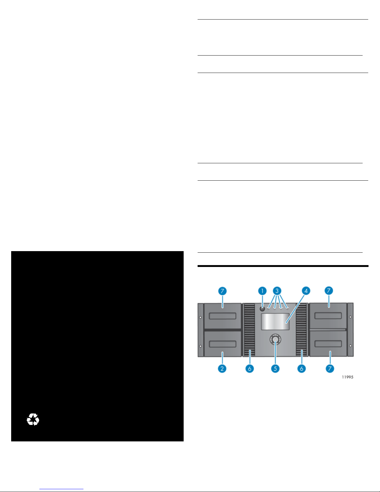
Front panel overview
2. Magazine and mailslot1. Power button
4. LCD screen3. LEDs
6. Air vents5. Control keys
7. Magazine
AL540-96015
Page 1
Page 2

Back panel overview: parallel SCSI
Back panel overview: Fibre Channel
(FC)
1. 68-pin HD parallel SCSI
connectors
9. Pull-out tab containing
product information
2. Fan
4. Tape drive assembly3. Power connector
6. Serial port (Factory use only)5. Ethernet port
8. Magazine release hole7. USB port
10. Tape drive assembly LED
Back panel overview: SAS
9. Pull-out tab containing product
information
Power supply LEDs
2. Fan1. Fibre Channel ports
4. Tape drive assembly3. Power connector
6. Serial port (Factory use only)5. Ethernet port
8. Magazine release hole7. USB port
10. Tape drive assembly LED
9. Pull-out tab containing product
information
2. Fan1. SAS port
4. Tape drive assembly3. Power connector
6. Serial port (Factory use only)5. Ethernet port
8. Magazine release hole7. USB port
10. Tape drive assembly LED
1. Blue
2. Yellow
3. Green
AC power is connected.
Fan failure. The fan is running too slow or is defective.
The power supply is producing good power for the
Library.
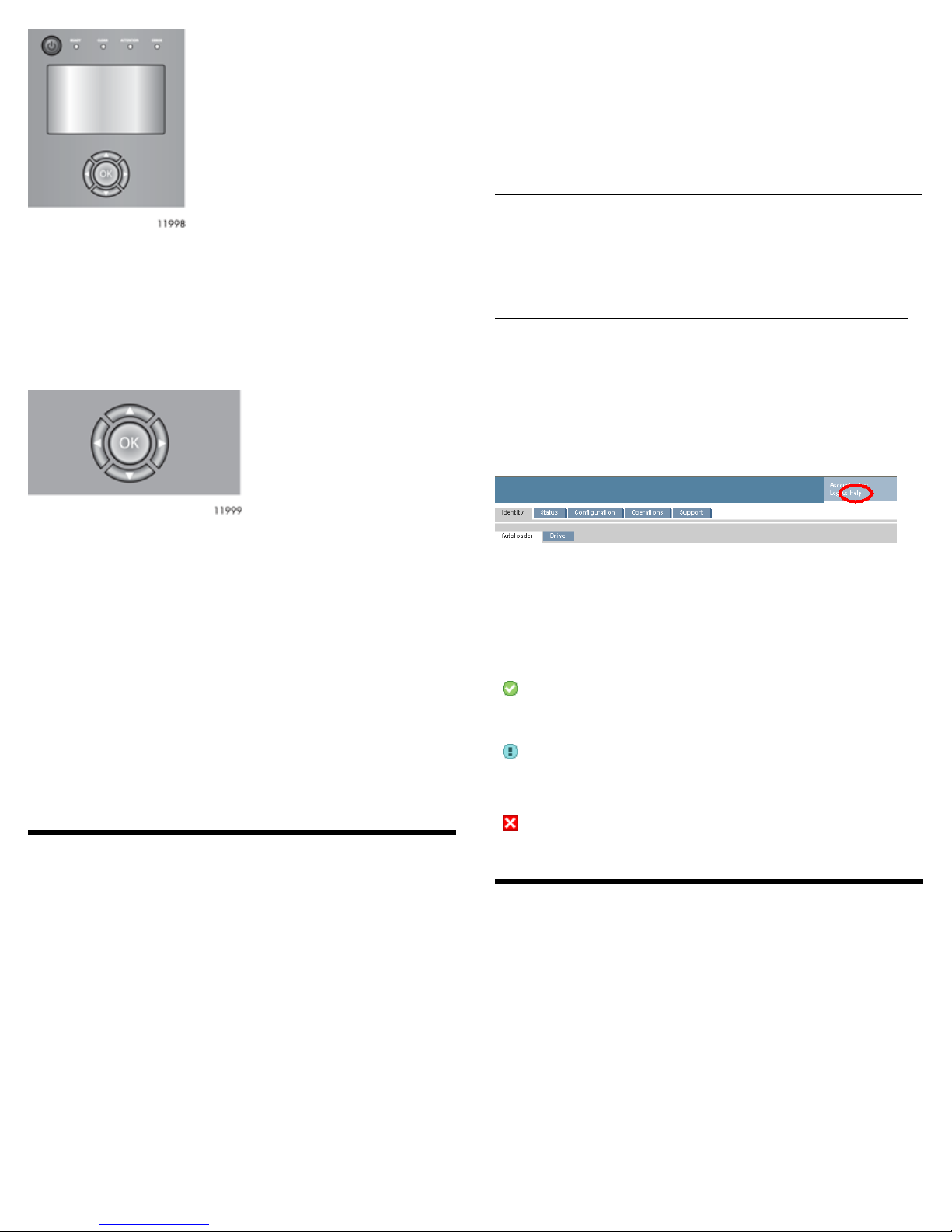
Using the operator control panel (OCP)
The OCP has a power button, four LEDs, five control keys, and an LCD
screen. With the OCP, you can monitor, configure, and operate most
Library functions from the Library front panel.
Page 2
Page 3
See “OCP menu” on page 10 for more information.
Control keys
The OCP displays a menu that lets you access information and execute
commands using the five control keys: Up, Down, Left, Right, and
OK.
To enable the Library RMI, follow the instructions in this installation
process to:
• Connect the Library to your local area network with an Ethernet
cable..
• Configure the network settings of the .
• If you intend to use the administrative functions of the RMI, set the
Administrator password using the OCP.
NOTE:
The Library is shipped without an administrator password. You
must set the administrator password with the OCP before you can
use the RMI administrator functions. Once the administrator
password is set, you can access the RMI by providing the
administrator password on the login screen.
Logging in
Using the OCP, find the Library IP address from the Info > Network
screen. Open any HTML web browser and enter the Library IP address.
Select the account type. For the administrator account, you must also
enter the administrator password. Click Sign In.
LED indicators
The OCP has four LEDs that provide information.
Ready— Green, steady when power is on, blinking with tape drive or
Library robotics activity.
Clean — Amber when a tape drive cleaning operation is recommended.
Attention — Amber if the Library has detected a condition that user
attention is necessary, but that the device can still perform most
operations.
Error— Amber if an unrecoverable tape drive or Library error occurs.
A corresponding error message displays on the LCD screen. User
intervention is required; the device is not capable of performing some
operations.
Using the remote management interface
(RMI)
With the RMI, you can monitor, configure, and operate most Library
functions from a web browser. The only tasks you cannot do from the
RMI are:
When possible, use the RMI as the primary Library interface because
the web interface provides access to additional features, includes online
help, and is easier to use. The only tasks you cannot do from the RMI
are:
• Opening the mailslots.
• Initiating the Wellness test.
• Saving and restoring configuration files, saving support tickets, and
downloading firmware via a USB flash drive.
Once signed in, click Help in the upper right-hand corner for more
information about the fields and information in the RMI.
Status icons
The green Status OK icon indicates that the Library is fully
operational and that no user interaction is required.
The blue exclamation point Status Warning icon indicates
that user attention is necessary, but that the device can still
perform most operations.
The red X Status Error icon indicates that user intervention
is required and that the device is not capable of performing
some operations.
Unpacking the Library
Remove the packaging, accessories, and Library from the box one layer
at a time. Place the Library on a level work surface. Carefully remove
the foam padding from the Library. Save the packaging materials to
move or ship the Library in the future.
Page 3
Page 4

1 Removing and storing the shipping
lock
The shipping lock protects the robotic transport mechanism from
moving during shipment and must be removed and stored before
powering on the Library.
Locate the adhesive tape holding the storage lock at the top of the
Library. Remove the adhesive tape, then remove the storage lock and
store it as shown.
IMPORTANT:
The shipping lock must be removed for the robotics to work
properly. A robot move error is displayed if the shipping lock is not
removed.
3 Installing tape drives
The Library can hold up to two full-height or up to four half-height
drives. If the Library will only have one tape drive, install it in the
bottom drive bay. (Tape drives are numbered from the bottom up.)
Add the new tape drive directly above the currently installed tape
drive. Remove one drive bay cover for a half-height tape drive or two
drive bay covers for a full-height tape drive.
NOTE:
The Library will not operate with a full-height tape drive installed
in the second and third half-height drive bays. Install a full-height
tape drive either in the bottom two drive bays or the top two drive
bays.
2 Installing a rail kit
Install the rail kit using the instructions that shipped with the rail kit.
Install the Library in the rails. To secure the Library to the rails, tighten
the two captive screws in the Library bezel.
Optional: Adding a power supply
With the redundant power supply upgrade kit, the Library will continue
to operate without interruption if either power supply fails.
To install the redundant power supply, remove the cover plate for the
redundant power supply with a #2 Phillips screwdriver. Slide the power
supply into the bay until it is firmly seated. Tighten the three blue
thumbscrews with your fingers to secure the power supply.
Slide the tape drive into the bay until it is firmly seated. Tighten the
blue thumbscrews with your fingers to secure the tape drive.
4a Planning the FC configuration
The FC tape drive has two FC ports. Only one port may be used at a
time, but both ports can be connected for path failover if your
application supports path failover.
Direct connection
You will need a 2 Gb or 4 Gb FC HBA. A 4 Gb HBA is recommended
LTO-4 tape drive for optimum performance.
SAN connection
All switches between the host and the Library must be of the
appropriate type. A 2 Gb switch in the path may result in performance
degradation when backing up highly compressible data to a 4 Gb tape
drive.
Configure zoning on the Fibre switch so only the backup servers can
access the Library.
Page 4
Page 5

NOTE:
See 12 Configuring the FC ports for additional FC configuration
information. See the 2U Tape Library and 4U Tape Libraryuser and
service guide for instructions on changing the FC configuration.
4b Planning the SAS configuration
The server must have a SAS HBA with an external connector.
1. Half-height tape drives with SCSI ID 4
NOTE:
Most SAS RAID controllers do not support Tape Libraries.
WARNING!
Do not connect the Library to a SAS RAID controller unless the
controller is qualified with the Library. The server might not be able
to boot when the Library is connected to a non-supported SAS RAID
controller.
4c Planning the parallel SCSI configuration
If you are unfamiliar with configuring parallel SCSI devices, read the
parallel SCSI configuration information in the 2U Tape Library and 4U
Tape Libraryuser and service guide.
2. Half-height tape drives with SCSI ID 5
5 Changing the SCSI ID
In a parallel SCSI Library, if you need to change the SCSI ID for one or
both of the tape drives, do so before connecting the Library to the host
computer.
1. Attach the power cord to the Library.
2. Power on the Library by pressing the power button on the front
panel.
3. Use the control keys below the LCD screen to highlight
Configuration > Drives > Drive #, where # is the number of the
tape drive whose SCSI ID you need to change. Press the OK key.
4. Press OK to select the highlighted block. Use the Up and Down
control keys to change the SCSI ID. Press OK to select the value.
5. Highlight Save and press OK to save the SCSI ID.
6. Change the SCSI ID of the other tape drive if necessary.
TIP:
The SCSI ID can also be changed from the RMI Configure: Drive
screen once the RMI is configured.
Follow these general guidelines when planning the parallel SCSI
configuration:
• Tape drives are Ultra320 parallel SCSI devices. Only attach one tape
drive per Ultra320 bus. Attaching a tape drive on a lower performance bus may degrade its performance. Do not connect an LTO tape
drive to an SE SCSI bus because it will seriously degrade performance.
• Avoid attaching the Library to the same SCSI bus as a disk drive
or SE device.
• The default SCSI ID of half-height tape drives is 4 or 5, depending
on the location of the tape drive in the Library as shown below.
6 Preparing the host
If necessary, install software, a host bus adapter (HBA), and compatible
drivers in the host computer.
For parallel SCSI and SAS Libraries, ensure that your HBA supports
multiple LUNs. For parallel SCSI devices, verify that multiple LUN
support is enabled for the HBA and operating system.
Power off the host server before attaching new devices.
7a Connecting the Library: FC
Remove the FC port dust cap from Port A. Attach one end of the FC
cable to Port A on the tape drive. Attach the other end of the FC cable
to a switch or HBA.
Page 5
Page 6

7b Connecting the Library: SAS
Ensure that the SAS cable used has enough mini-SAS connectors for
the number of drives installed in the Library.
Otherwise, attach a SCSI cable to the next device on the SCSI bus. Make
sure that the last device on the SCSI bus is properly terminated.
Connect the other tape drives, if applicable.
NOTE:
For optimal performance, a parallel SCSI tape drive should be the
only device on the bus.
8 Powering on the Library
CAUTION:
Mini-SAS connectors are keyed. Do not force a SAS cable's mini-SAS
connector into the tape drive mini-SAS connector because it might
be keyed differently.
CAUTION:
SAS signal rates require clean connections with a minimum number
of connections between the HBA and the Library. Do not use adapters
or converters between the HBA and the Library. For reliable
operation, use a maximum SAS cable length of six meters.
Attach the HBA end of the cable to the SAS HBA. Attach a connector
to each tape drive.
The unused ends of a fanout cable are single channel and not suitable
for use with most disk arrays. Use the other ends to connect tape drives,
or coil and secure them to the rack to minimize stress on the connectors.
Plug one end of the Ethernet cable into the Ethernet port on the back
of the Library. Plug the other end of the cable into an Ethernet LAN
port.
Plug the power cable into the Library from an AC power outlet. Repeat
for the redundant power supply, if installed.
Power on the Library using the power button located on the front panel.
Check the LCD screen to make sure the Library is receiving power.
Power on the host server and all devices you powered off earlier.
9 Configuring the network
Configuring the network enables you to monitor, configure, and control
most Library functions from the remote management interface (RMI).
By default, the Library will request an IP address from a DHCP server.
Optionally, you can configure the Library to use a static IP address.
Once logged into the RMI, you can administer further network changes
through the RMI.
NOTE:
Most IPv4 network configurations are also available through the
OCP.
NOTE:
Each of the tape drives uses one channel and the cable supplied with
the 2U Tape Library or 4U Tape Library maps each of the four
channels from the HBA to one channel on the drive end. You can
plug any of the four drive connectors into any tape drive.
7c Connecting the Library: parallel SCSI
Attach one end of the parallel SCSI cable to one of the connectors on
the tape drive. Attach the other end of the cable to the host bus adapter
(HBA) or to the connector on the previous device on the SCSI bus.
If the tape drive is the last or only device on the SCSI bus, attach a
terminator to the remaining SCSI connector on the tape drive.
The Library supports IPv4 and IPv6 Internet Protocols. By default, the
Library is configured to use IPv4, the most common current version.
You can enable IPv6 or both Internet Protocols from the OCP or RMI,
and then continue configuring IPv6 settings from the RMI.
NOTE:
The Library is shipped without an administrator password. You
must set the administrator password with the OCP before you can
use the RMI administrator functions. Once the administrator
password is set, you can access the RMI by providing the
administrator password on the login screen.
To find the IPv4 IP address obtained via DHCP:
1. From the Home screen, press Next until the display shows
Status/Information. Press Enter.
Page 6
Page 7

2.
Press Next until the display shows Network Information. Press
Enter.
3.
The display shows IPv4 Network Enabled. Press Enter.
4. Press Next until the display shows the IP address.
5. Press Cancel until the display shows the home screen.
To set the IPv4 IP address or enable IPv6:
1. From the Home screen, press Next until the display shows
Configuration. Press Enter.
2.
Press Next until the display shows Configure Network
Settings. Press Enter.
3.
The display shows IPv4 Network Enabled. To change the
setting, press Enter. Press Next until the display shows the desired
setting. Press Enter to accept the new setting.
4.
Press Next until the display shows IPv6 Networking. To enable
IPv6 networking, press Enter. The display shows IPv6 Network
Disabled. To change the setting, press Enter. Press Next until
the display shows the desired setting. Press Enter to accept the
new setting.
1. On the front panel, highlight Configuration > Set Date and Time.
Press OK.
2. Press OK to select the first block that can be edited. Use the Left
and Right control keys to move between digits in the Date and
Time fields. Use the Up and Down control keys to change the
value of the highlighted digit. When the screen shows the desired
value, press OK.
NOTE:
When setting the hours, the time is based on a 24-hour clock. There
is no a.m. or p.m. designation. For example, 1:00 p.m. is 13:00.
NOTE:
The Library time does not automatically adjust for daylight saving
time; you must adjust the time manually through the OCP or RMI.
If IPv4 networking is enabled, you can continue configuring the IPv4
network settings from the OCP:
1. From the Home screen, press Next until the display shows
Configuration. Press Enter.
2.
Press Next until the display shows Configure Network
Settings. Press Enter.
3.
Press Next until the display shows IPv4 Networking. Press
Enter.
4.
Press Next until the display shows DHCP (IPv4) Enabled. To
change the setting, press Enter. Press Next until the screen displays
the desired setting. Press Enter to accept the new setting.
5.
If DHCPv4 is disabled, press Next to display the IP address.
Tochange the IP address, press Enter. Set the new IP address with
the Next and Enter keys.
6. Press Next to display the subnet mask. To change the subnet mask,
press Enter. Set the new subnet mask with the Next and Enter
keys.
7. Press Next to display the gateway address. To change the gateway
address, press Enter. Set the new subnet address with the Next
and Enter keys.
If you enabled IPv6, you must continue configuring IPv6 from the RMI
after setting the administrator password in Step 11. You can find the
IPv6 IP address obtained by the Library from the OCP
Information/Status > Network Information menu item. See
the 2U Tape Library and 4U Tape Library user and service guide included
in the product documentation for additional information on configuring
IPv6.
11 Setting the administrator password
Setting an administrator password provides access to the administrator
functions with the RMI and OCP, and restricts access to administrator
functions to only those who know the administrator password. The
Library comes with a null administrator password, which until set
allows unrestricted access to all administrative functions through the
OCP but not the RMI. Once the administrator password has been set
from the OCP, it can be changed from either the OCP or the RMI. The
administrator password must be exactly eight digits consisting of the
numbers 0 through 9.
To set the administrator password:
1. On the OCP, press Enter.
2.
Press Next until the display shows Configuration. Press Enter.
3. Press Enter to change the administrator password.
4. The first number will flash. Press Next until the first number for
the new password is displayed. Press Enter to accept the number.
The next number flashes. Repeat for each number in the password.
5. Press Cancel twice to move to the top of the menu.
12 Configuring the FC ports
For most situations, leave the FC ports at the default settings of Port
Speed: Automatic and Port Type: Auto Detect. With these settings,
the tape drive will choose the appropriate configuration. See the 2U
Tape Library and 4U Tape Libraryuser and service guide for instructions
on changing the FC configuration.
10 Setting the date and time
This option sets the date and time used by the Library to record events
and should be set during the initial installation process. You can also
set the date and time from the RMI Configure: System screen.
To set the date and time from the OCP:
Page 7
Page 8

13 Labeling tape cartridges
Attaching a bar code label to each tape cartridge enables the Library
and application software to identify the cartridge quickly, thereby
speeding up inventory time. Make it a practice to use bar code labels
on your tape cartridges.
IMPORTANT:
The misuse and misunderstanding of bar code technology can result
in backup and restore failures. To ensure that your bar codes meet
quality standards, always purchase them from an approved supplier
and never print bar code labels yourself.
LTO tape cartridges have a recessed area located on the face of the
cartridge next to the write-protect switch. Use only this recessed area
for attaching the adhesive-backed bar code label. Only apply labels as
designated.
To see the firmware revision of the Library on the front panel:
1. Use the control keys to navigate to Info > Identity > Library.
2. The Library Controller FW Revision field shows the Library
firmware revision.
16 Configuring additional features
The Library has many features to customize for your organization. See
the Addendum included with the product documentation and the 2U
Tape Library and 4U Tape Library user and service guide for more
information about these features and instructions for their configuration.
• Partitioning a Library into logical libraries.
• Configuring IPv6 networking.
• Enabling and configuring SNMP network management.
• Naming the Library.
Slot numbering (without the mailslot
enabled)
To use the mailslot feature, leave the bottom slot in the front of the left
magazine empty. The rest of the slot numbers are adjusted as shown.
14 Loading tape cartridges
You can use the mailslot to import and export tape cartridges. To load
or unload more tape cartridges at a time, you can remove the magazines
and load the cartridges into them. Use the front panel Operations >
Unlock Left Magazines option to release the left magazines. If
requested, provide the administrator password to access the magazines.
Pull both magazines straight out of the front of the Library.
The lower left magazine, which is designated by a white dot on the
lower right corner, has a three-slot mailslot in the front of the magazine.
Leave the three slots in the front of the magazine empty if you plan to
enable the mailslot.
Insert the tape cartridges into the magazines.
Replace the magazines in the Library.
Repeat for the right magazines.
15 Verifying the installation
NOTE:
When the mailslot is enabled, the slots in the lower-left magazine
are numbered as below. All other slots are renumbered.
Verify that the Library has the most up-to-date firmware revision and
upgrade the firmware if necessary. You can upgrade firmware from
the OCP using a USB flash drive or through the RMI.
Page 8
Page 9

Magazine release
When possible, release the magazines from the OCP or RMI. If you
must remove the magazines when the Library is not powered on, 1)
insert a straightened paperclip or small pin about 1.5 cm (0.6 inch) into
the magazine release hole on the back panel, while 2) another person
removes the magazines from that side.
IMPORTANT:
Do not force the pin once you encounter resistance. Doing so can
damage the Library.
TIP:
To see the slot numbering for your Library in its current
configuration, see the RMI Status > Inventory screen.
Ordering media
Mailslot
Enabling the mailslot in the left magazine allows you to insert and
remove tapes without removing the magazine and without the need
for the administrative password. You can open the mailslot from the
front panel or with host software that supports this function. The
mailslot cannot be opened with the RMI.
Use only recommended media to prolong the life of the Library and
tape drives. Various vendors offer appropriate media.
Related documentation
The 2U Tape Library and 4U Tape Library user and service guide includes
additional information about installing, configuring, upgrading, and
operating the Library.
(c) Copyright 2009 Hewlett-Packard Development Company, L.P.
When the mailslot is enabled, the mailslot uses the front three slots of
the lower left magazine and the storage slots are renumbered as shown.
Page 9
Page 10

OCP menu
Page 10
 Loading...