

Page 1
Overland
Storage
NEO® 200s/400s Library
User Guide
April 2012
10400367-001
Page 2

NEO 200s/400s User Guide
©2012 Overland Storage, Inc. All rights reserved.
Overland®, Overland Data®, Overland Storage®, LibraryPro®, LoaderXpress®, Multi-SitePAC®, NEO®, NEO Series®,
PowerLoader
XchangeNOW
GuardianOS™, SnapWrite™, Snap Enterprise Data Replicator™, SnapExpansion™, SnapSAN™, and SnapServer Manager™ are
trademarks of Overland Storage, Inc.
All other brand names or trademarks are the property of their respective owners.
The names of companies and individuals used in examples are fictitious and intended to illustrate the use of the software. Any
resemblance to actual companies or individuals, whether past or present, is coincidental.
PROPRIETARY NOTICE
All information contained in or disclosed by this document is considered proprietary by Overland Storage. By accepting this material
the recipient agrees that this material and the information contained therein are held in confidence and in trust and will not be
used, reproduced in whole or in part, nor its contents revealed to others, except to meet the purpose for which it was delivered. It is
understood that no right is conveyed to reproduce or have reproduced any item herein disclosed without express permission from
Overland Storage.
Overland Storage provides this manual as is, without warranty of any kind, either expressed or implied, including, but not limited
to, the implied warranties of merchantability and fitness for a particular purpose. Overland Storage may make improvements or
changes in the products or programs described in this manual at any time. These changes will be incorporated in new editions of
this publication.
Overland Storage assumes no responsibility for the accuracy, completeness, sufficiency, or usefulness of this manual, nor for any
problem that might arise from the use of the information in this manual.
®
, Protection OS®, REO®, REO 4000®, REO Series®, Snap Care®, SnapServer®, StorAssure®, WebTLC®, and
®
are registered trademarks of Overland Storage, Inc.
Overland Storage, Inc.
9112 Spectrum Center Blvd.
San Diego, CA 92123
U.S.A.
Tel: 1.877.654.3429 (toll-free U.S.)
Tel: +1.858.571.5555, Option 5 (International)
Fax: +1.858.571.0982 (general)
Fax: +1.858.571.3664 (sales)
www.overlandstorage.com
10400367-001 04/2012
©2012 Overland Storage, Inc. W ii
Page 3

Audience and Purpose
Preface
This guide is intended for system and network administrators charged with installing and
maintaining Overland Storage
information on the installation, configuration, security, and maintenance of those libraries.
It assumes you are familiar with basic functions of your computer, Serial Attached SCSI
(SAS), and Fibre Channel (FC), as well as networking concepts and terminology. It also
assumes you are knowledgeable about the Storage Area Network (SAN) to which your NEO
S-series library is being connected.
This product is not intended to be connected directly or indirectly, by any means whatsoever,
to interfaces of public telecommunications networks.
Product Documentation
NEO product documentation and additional literature are available online. Point your
browser to:
http://docs.overlandstorage.com/neo
For additional assistance, search at http://support.overlandstorage.com.
Overland Technical Support
®
NEO 200s/400s libraries on their network. It provides
For help configuring and using your NEO 200s/400s libraries, search at:
http://support.overlandstorage.com/kb
You can email our technical support staff at techsupport@overlandstorage.com or get
additional technical support information on the Contact Us web page:
http://docs.overlandstorage.com/support
For a complete list of support times depending on the type of coverage, visit our website at:
http://docs.overlandstorage.com/care
10400367-001 04/2012 ©2012 Overland Storage, Inc. W iii
Page 4
NEO 200s/400s User Guide
Conventions
This document exercises several alerts and typographical conventions.
Alerts
Typographical Conventions
Convention Description & Usage
IMPORTANT An Important note is a type of note that provides information essential to
the completion of a task or that can impact the product and its function.
CAUTION A Caution contains information that the user needs to know to avoid
damaging or permanently deleting data or causing physical damage to
the hardware or system.
WARNING
ADVERTISSEMENT
A Warning contains information concerning personal safety. Failure to
follow directions in the warning could result in bodily harm or death.
Un Canadien avertissement comme celui-ci contient des informations
relatives à la sécurité personnelle. Ignorer les instructions dans
l'avertissement peut entraîner des lésions corporelles ou la mort.
Convention Description & Usage
Button_name
Ctrl-Alt-r This type of format details the keys you press simultaneously. In this
NOTE A Note indicates neutral or positive information that emphasizes or
Menu Flow
Indicator (>)
Courier Italic A variable for which you must substitute a value
Courier Bold
Information contained in this guide has been reviewed for accuracy, but not for product
warranty because of the various environments, operating systems, or settings involved.
Information and specifications may change without notice.
Software Updates
Words in this special boldface font indicate command buttons found in
the
Web User Interface.
example, hold down the Ctrl and Alt keys and press the r key.
supplements important points of the main text. A note supplies
information that may apply only in special cases, for example, memory
limitations or details that apply to specific program versions.
Words with a greater than sign between them indicate the flow of actions
to accomplish a task. For example,
indicates that you should press the
button, and finally the
Commands you enter in a command-line interface (CLI)
User button to accomplish a task.
Setup > Passwords > User
Setup button, then the Password
The latest release of the NEO 200s/400s firmware can be obtained from the Downloads and
Resources – NEO Series page at the Overland Storage website:
Follow the appropriate instructions to download the latest software file.
For additional assistance, search at http://support.overlandstorage.com/
10400367-001 04/2012
http://docs.overlandstorage.com/neo
©2012 Overland Storage, Inc. W iv
Page 5
NEO 200s/400s User Guide
Finding More Information
Product documentation related to NEO 200s/400s is listed below. The current versions of all
these documents are always available from the Overland Storage NEO Download and
Resources website (http://docs.overlandstorage.com/neo).
Source Location Content
Quick Start Guide Product Packaging
and Web
User Guide eDoc on Web Provides an overview of the configuration,
Online Help Web User
Interface
Electrostatic Discharge Information
A discharge of static electricity can damage static-sensitive devices. Proper packaging and
grounding techniques are necessary precautions to prevent damage. To prevent electrostatic
damage, observe the following precautions:
• Transport products in static-safe containers such as conductive tubes, bags, or boxes.
• Cover the appliance with approved static-dissipating material.
• Use a wrist strap connected to the work surface and properly-grounded tools and
equipment.
• Keep the work area free of non-conductive materials such as foam packing materials.
• Make sure you are always properly grounded when touching a static-sensitive
component or assembly. Avoid touching pins, leads, or circuitry.
Provides complete instructions for installing the
server into a rack and connecting the server to the
network. Also contains links to warranty registration
and information.
maintenance, and troubleshooting of the NEO
200s/400s, and detailed instructions on using the
remote access
Basic troubleshooting information embedded in the
firmware.
Web User Interface.
Safety and Environmental Notices
The sections that follow define each type of safety notice and give examples.
Laser Safety and Compliance
Before using the library, review the following laser safety information.
Class I Laser Product
The library may contain a laser assembly that complies with the performance
standards set by the U.S. Food and Drug Administration for a Class I laser
product. Class I laser products do not emit hazardous laser radiation. The library
has the necessary protective housing and scanning safeguards to ensure that laser
radiation is inaccessible during operation or is within Class I limits. External
safety agencies have reviewed the library and have obtained approvals to the latest
standards as they apply.
10400367-001 04/2012
©2012 Overland Storage, Inc. W v
Page 6
NEO 200s/400s User Guide
Cautions and Regulatory Compliance Statements for NEBS
This library is NEBS certified. This section includes the cautions and regulatory compliance
statements for the Network Equipment-Building System (NEBS) certification from the
Telcordia Electromagnetic Compatibility and Electrical Safety – Generic Criteria for
Network Telecommunications Equipment (A Module of LSSGR, FR-64; TSGR, FR-440; and
NEBSFR, FR-2063) Telcordia Technologies Generic Requirements, GR-1089-CORE, Issue 4,
June 2006.
NEBS Compliance Statements
CAUTION: To comply with the Telcordia GR-1089-CORE standard for electromagnetic
compatibility and safety, for Ethernet RJ-45 ports, use only shielded Ethernet cables that are
grounded on both ends. In a NEBS installation, all Ethernet ports are limited to intra-building wiring.
CAUTION: The intra-building ports of the equipment or subassembly are only suitable for
connection to intra-building or unexposed wiring or cabling. The intra-building ports of the
equipment or subassembly MUST NOT be metallically connected to interfaces that connect to the
OSP or its wiring. These interfaces are designed for use only as intra-building interfaces (Type 2 or
Type 4 ports as described in GR-1089-CORE, Issue 4), and require isolation from the exposed OSP
cabling. The addition of primary protectors is not sufficient protection in order to connect these
interfaces metallically to OSP wiring.
An external Surge Protective Device (SPD) is not required for operating this library.
This product can be installed in a network telecommunication facility or location where the
NEC applies.
Product Recycling and Disposal
This unit contains recyclable materials.
This unit must be recycled or discarded according to applicable local and national
regulations. Overland Storage encourages owners of information technology (IT) equipment
to responsibly recycle their equipment when it is no longer needed.
This paragraph is also translated into Spanish (Español) as follows:
Esta unidad debe reciclarse o desecharse de acuerdo con lo establecido en la normativa
nacional o local aplicable. Overland Storage recomienda a los propietarios de equipos de
tecnología de la información (TI) que reciclen responsablemente sus equipos cuando éstos ya
no les sean útiles.
Notice: This mark applies only to countries within the European Union (EU) and Norway.
10400367-001 04/2012
©2012 Overland Storage, Inc. W vi
Page 7
NEO 200s/400s User Guide
Appliances are labeled in accordance with European Directive 2002/96/EC concerning waste
electrical and electronic equipment (WEEE). The Directive determines the framework for
the return and recycling of used appliances as applicable throughout the European Union.
This label is applied to various products to indicate that the product is not to be thrown
away, but rather reclaimed upon end of life per this Directive.
Remarque: Cette marque s'applique uniquement aux pays de l'Union Européenne et à la
Norvège.
L'etiquette du système respecte la Directive européenne 2002/96/EC en matière de Déchets
des Equipements Electriques et Electroniques (DEEE), qui détermine les dispositions de
retour et de recyclage applicables aux systèmes utilisés à travers l'Union européenne.
Conformément à la directive, ladite étiquette précise que le produit sur lequel elle est
apposée ne doit pas être jeté mais être récupéré en fin de vie.
In accordance with the European WEEE Directive, electrical and electronic equipment
(EEE) is to be collected separately and to be reused, recycled, or recovered at end of life.
Users of EEE with the WEEE marking per Annex IV of the WEEE Directive, as shown
above, must not dispose of end of life EEE as unsorted municipal waste, but use the
collection framework available to customers for the return, recycling, and recovery of WEEE.
Customer participation is important to minimize any potential effects of EEE on the
environment and human health due to the potential presence of hazardous substances in
EEE. For proper collection and treatment, contact your local Overland representative.
10400367-001 04/2012
©2012 Overland Storage, Inc. W vii
Page 8

Preface
Chapter 1 – Product Description
Physical Library ...................................................................................................................................................... 1-1
Front Panel ....................................................................................................................................................... 1-1
Rear Panel ....................................................................................................................................................... 1-3
Bar Code Reader ............................................................................................................................................ 1-5
Networking ............................................................................................................................................................ 1-5
Supported Internet Protocols ........................................................................................................................ 1-5
Simple Network Management Protocol (SNMP) Messaging ..................................................................... 1-5
Network Time Protocol (NTP) ......................................................................................................................... 1-6
Maximum Library Storage Capacity and Data Transfer Rate ................................................................... 1-6
Ultrium Tape Drives ............................................................................................................................................... 1-7
Speed Matching ............................................................................................................................................. 1-7
Channel Calibration ....................................................................................................................................... 1-7
Power Management ...................................................................................................................................... 1-7
Media ..................................................................................................................................................................... 1-8
Contents
Chapter 2 – User Interfaces
Operator Control Panel ....................................................................................................................................... 2-1
Front Panel LEDs ..............................................................................................................................................2-3
Input Modes .................................................................................................................................................... 2-4
Web User Interface ............................................................................................................................................... 2-5
Login ................................................................................................................................................................. 2-6
System Status ................................................................................................................................................... 2-6
Web User Interface Help Pages .................................................................................................................... 2-8
Logging out of the Web User Interface ....................................................................................................... 2-8
Chapter 3 – Installation Planning
Determining Number of Logical Libraries .......................................................................................................... 3-1
Basic Guidelines ..............................................................................................................................................3-1
Library Sharing ................................................................................................................................................. 3-1
Library Partitioning and Element Addressing .....................................................................................................3-1
Configuration of a One-Partition System ..................................................................................................... 3-2
Configuration of a Two-Partition System ...................................................................................................... 3-2
Configuration of a Three-Partition System ...................................................................................................3-3
Configuration of a Four-Partition System ..................................................................................................... 3-3
Using Persistent Binding ........................................................................................................................................ 3-4
Logical Unit Number (LUN) Scanning ................................................................................................................. 3-4
Host Interfaces ......................................................................................................................................................3-4
SAS Interface ................................................................................................................................................... 3-4
10400367-001 04/2012 ©2012 Overland Storage, Inc. W v
Page 9

NEO 200s/400s User Guide
Fibre Channel Interface ................................................................................................................................. 3-4
Chapter 4 – Installation & Configuration
Choosing a Location ............................................................................................................................................ 4-1
Installing in a Rack ................................................................................................................................................4-2
Register to Activate Your Warranty ..............................................................................................................4-2
Remove the Shipping Lock ............................................................................................................................ 4-2
Rack Installation ..............................................................................................................................................4-3
Install Any Add-on Components ................................................................................................................... 4-5
Cable Attachment ......................................................................................................................................... 4-6
Power Cord Attachment ............................................................................................................................... 4-7
Configure Library Settings .................................................................................................................................... 4-8
Using Factory Defaults as Your Configuration ............................................................................................. 4-8
Configuring Your Library – Web User Interface .................................................................................................4-8
Establishing Remote Access to Your Library ................................................................................................4-9
Logging in to the Web User Interface ........................................................................................................ 4-10
Checking Firmware Level ............................................................................................................................ 4-10
Configuring Library Settings ......................................................................................................................... 4-11
Drive Interface Identification and Settings ................................................................................................ 4-13
Configuring Network Settings ...................................................................................................................... 4-13
Configuring User Access .............................................................................................................................. 4-15
Configuring Date and Time Settings ........................................................................................................... 4-16
Configuring Logs and Traces ....................................................................................................................... 4-16
Configuring Email Notifications ................................................................................................................... 4-17
Configuring SMNP Settings .......................................................................................................................... 4-18
Restoring Factory Default Settings .............................................................................................................. 4-18
Logging Out .................................................................................................................................................. 4-18
Configuring Your Library – Operator Control Panel ........................................................................................ 4-19
Logging in to the Operator Control Panel ................................................................................................. 4-19
Configuring Logical Libraries ....................................................................................................................... 4-19
Configuring Library Settings ......................................................................................................................... 4-20
Configuring Drives ........................................................................................................................................ 4-22
Configuring Network Settings ...................................................................................................................... 4-23
Configuring the Access PIN ......................................................................................................................... 4-24
Configuring Save/Restore Settings ............................................................................................................. 4-25
Configuring Date and Time ......................................................................................................................... 4-27
Preparing the Host ..............................................................................................................................................4-27
Verifying the Connection .................................................................................................................................. 4-27
Cartridge Magazines ......................................................................................................................................... 4-27
2U Library Cartridge Magazines .................................................................................................................. 4-28
2U Library Mail Slot (I/O Station) .................................................................................................................. 4-28
4U Library Cartridge Magazines .................................................................................................................. 4-29
4U Library Mail Slots (I/O Station) ................................................................................................................ 4-29
Populating the Library with Data Cartridges ................................................................................................... 4-30
Inserting the Cleaning Cartridge ...................................................................................................................... 4-30
Registering for Support Notification .................................................................................................................. 4-31
Chapter 5 – Operations
Operator Control Panel Navigation ................................................................................................................... 5-1
Operator Control Panel Menus ........................................................................................................................... 5-2
Monitor Menu ..................................................................................................................................................5-2
10400367-001 04/2012
©2012 Overland Storage, Inc. W vi
Page 10

NEO 200s/400s User Guide
Control Menu ..................................................................................................................................................5-7
Configure Menu ..............................................................................................................................................5-8
Service Menu .................................................................................................................................................. 5-8
Web User Interface Menus ................................................................................................................................ 5-11
Monitor Library Menu ................................................................................................................................... 5-11
Manage Library Menu ................................................................................................................................. 5-16
Configure Library Menu ............................................................................................................................... 5-17
Service Library Menu .................................................................................................................................... 5-26
Import and Export Media during Normal Library Operation .........................................................................5-31
Import Media ................................................................................................................................................5-31
Export Media ................................................................................................................................................. 5-32
Configuring Mail Slots and Reserving Slots ...................................................................................................... 5-32
Mail Slot Configuration ................................................................................................................................. 5-32
Reserving Slots ............................................................................................................................................... 5-33
Chapter 6 – Media
Data Cartridges .................................................................................................................................................... 6-2
Cartridge Compatibility ................................................................................................................................. 6-3
Capacity Scaling ............................................................................................................................................ 6-3
Write Once, Read Many (WORM) ...................................................................................................................... 6-3
WORM Media .................................................................................................................................................. 6-3
Data Security on WORM Media .................................................................................................................... 6-3
WORM Media Errors ........................................................................................................................................ 6-4
Requirements for WORM Capability ............................................................................................................ 6-4
Cleaning Cartridge ..............................................................................................................................................6-4
Cartridge Memory Chip (LTO-CM) ..................................................................................................................... 6-4
Bar Code Labels ................................................................................................................................................... 6-5
Guidelines for Using Bar Code Labels .......................................................................................................... 6-6
Write-Protect Switch ............................................................................................................................................. 6-7
Cartridge Care and Handling ............................................................................................................................. 6-7
Provide Training ............................................................................................................................................... 6-7
Ensure Proper Packaging ............................................................................................................................... 6-8
Provide Proper Acclimation and Environmental Conditions .....................................................................6-8
Perform a Thorough Inspection ..................................................................................................................... 6-9
Handle the Cartridge Carefully .................................................................................................................. 6-10
Environmental and Shipping Specifications for Tape Cartridges .................................................................6-10
Disposing of Tape Cartridges ............................................................................................................................ 6-10
Ordering Media Supplies ................................................................................................................................... 6-11
Chapter 7 – Troubleshooting
Troubleshooting Table .......................................................................................................................................... 7-1
Installation Problems ............................................................................................................................................. 7-6
Library Recovery Problem Determination ......................................................................................................... 7-7
Procedures for Isolating CRU Problems .............................................................................................................. 7-7
Isolating a Power Supply Problem ................................................................................................................7-7
Isolating Drive Sled Problems ......................................................................................................................... 7-9
Isolating a Library Controller Card vs. Accessor Enclosure Problem ...................................................... 7-10
Isolating Web User Interface Problems ...................................................................................................... 7-11
Isolating Bar Code Scanner Problems ........................................................................................................ 7-12
Isolating Host Attachment Interface Problems .........................................................................................7-12
Identifying a Suspect Cartridge ........................................................................................................................ 7-12
10400367-001 04/2012
©2012 Overland Storage, Inc. W vii
Page 11

NEO 200s/400s User Guide
Contacting Overland Technical Support ........................................................................................................ 7-13
Chapter 8 – Error Codes
Preparing to Resolve an Error Code ................................................................................................................... 8-1
Error Codes ............................................................................................................................................................8-2
Sub Error Codes .................................................................................................................................................... 8-6
Warning Events ..................................................................................................................................................... 8-9
Chapter 9 – Service Procedures
Removing Cartridges from Magazine Slots ....................................................................................................... 9-1
Releasing the Magazines Manually ................................................................................................................... 9-1
TotalStorage Tape Diagnostic Tool (ITDT) .......................................................................................................... 9-2
Contacting Overland Technical Support .......................................................................................................... 9-3
Appendix A – Specifications
Physical Specifications ........................................................................................................................................ A-1
Electrical Specifications ...................................................................................................................................... A-1
Environmental Specifications ............................................................................................................................. A-1
Operational Specifications ................................................................................................................................. A-2
Product Environment .......................................................................................................................................... A-3
Supported Device Drivers ................................................................................................................................... A-3
Appendix B – Physical Configurations
2U Library Physical Configuration ....................................................................................................................... B-1
4U Library Physical Configuration ....................................................................................................................... B-2
Library Partitioning and Element Addressing .....................................................................................................B-3
Partitioning of 2U Libraries .............................................................................................................................. B-3
Partitioning of 4U Libraries .............................................................................................................................. B-3
SCSI Element Addressing ............................................................................................................................... B-5
Appendix C – TapeAlert Flags
Library Supported TapeAlert Flags .................................................................................................................... C-1
Tape Drive Supported TapeAlert Flags ............................................................................................................. C-3
Master Glossary & Acronym List
Index
10400367-001 04/2012
©2012 Overland Storage, Inc. W viii
Page 12
Chapter 1
Product Description
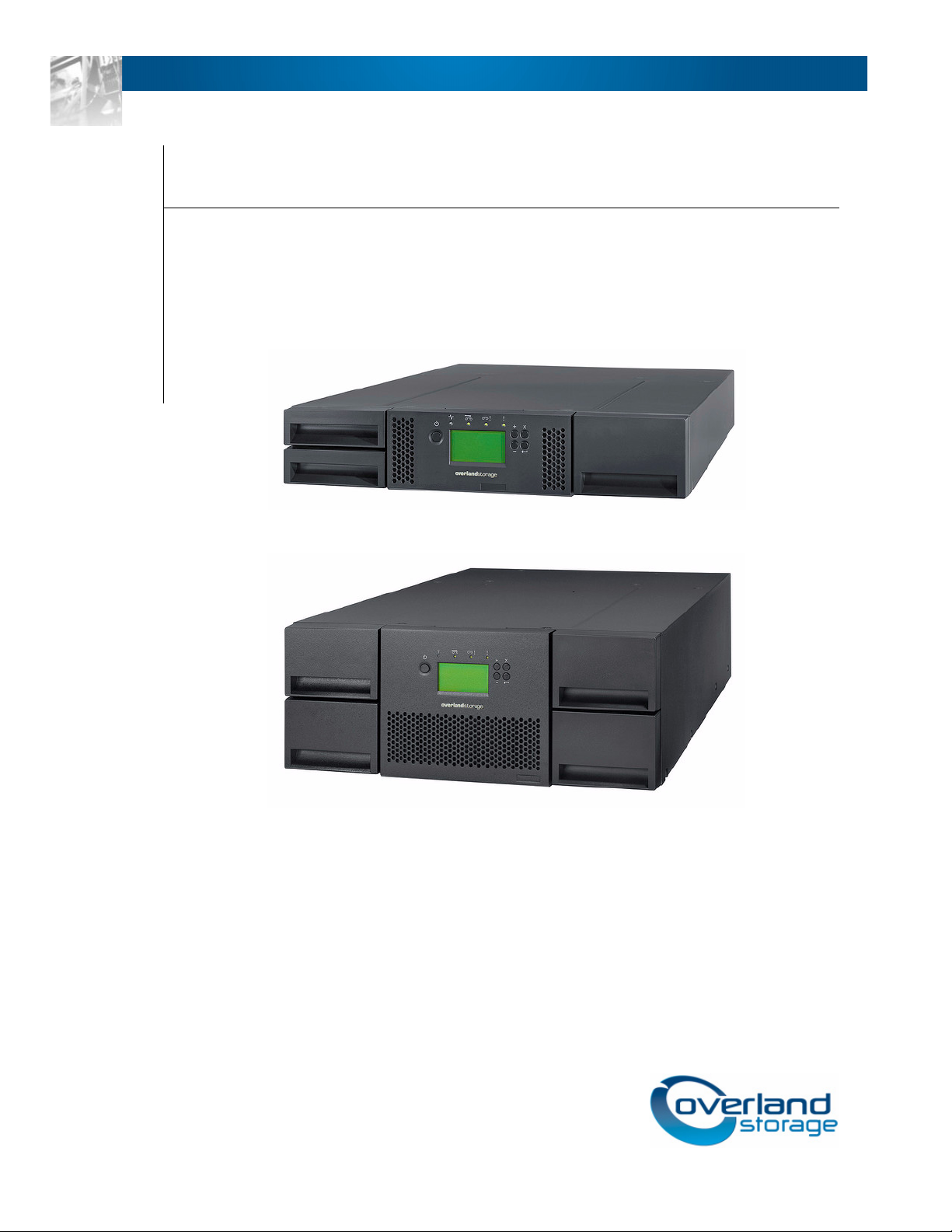
The NEO 200s and NEO 400s tape libraries provide compact, high-capacity, low-cost
solutions for simple, unattended data backup. The 4U library houses up to 48 tape
cartridges (or 45 and an elective 3-tape Mail Slot) in a compact 4U form factor with easy
access to cartridges via four removable magazines. The 2U library houses up to 24 tape
cartridges (or 23 and an elective 1-tape Mail Slot) in a compact 2U form factor with easy
access to cartridges via two removable magazines.
The NEO 200s/400s tape libraries are rack-mountable units that incorporate Ultrium 5
Half-Height or Ultrium 4 Half-Height tape drives. The drives are equipped with a SAS host
adapter interface that has a data transfer rate of up to 6.0 Gbps, or a Fibre Channel
interface.
Topics in Product Description:
• Physical Library
• Networking
• Ultrium Tape Drives
• Media
Physical Library
These sections describe the physical aspects of the libraries.
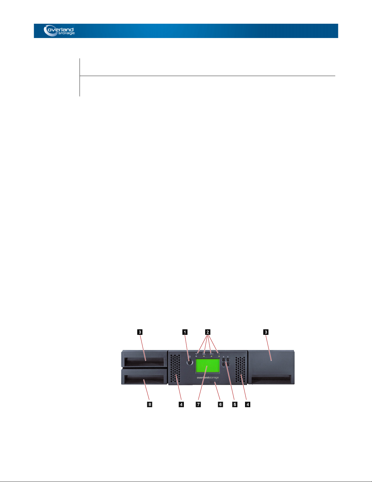
Front Panel
These graphics and table illustrate the front panel components:
10400367-001 04/2012 ©2012 Overland Storage, Inc. W 1-1
Page 13
NEO 200s/400s User Guide Physical Library
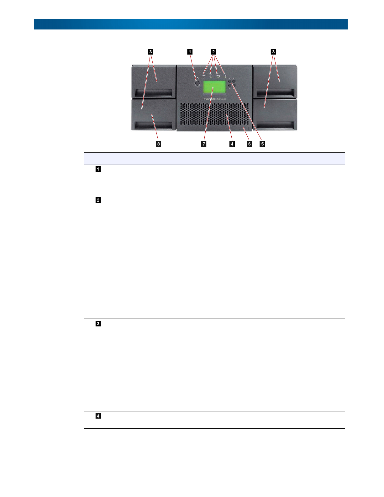
Number Item Description
Power button Pressing this button powers ON the library. Pressing and holding
this button for 4 seconds will power OFF the unit (soft power
down). No power switch or button can be found on the back
panel of the library.
Front panel LEDs (left to
right)
• Ready/Activity (Green LED)
– It is illuminated any time the unit
is powered ON and able to function. It should blink whenever
there is library or drive activity, or when the library is in the
process of powering up.
• Clean Drive (Amber LED)
– It is illuminated when the drive
needs to be cleaned. The LED will be turned OFF after the
drive is cleaned successfully.
• Attention (Amber LED)
– It is illuminated when there has been
a failure that indicates a piece of media is bad, marginal, or
invalid. It will be cleared when all invalid cartridges have been
exported from the library. The amber LED may also be lit
because a power supply or a power supply fan is failing, or a
drive sled is defective, missing, or has been replaced by a
different drive type.
• Error (Amber LED)
– It is illuminated when there is an
unrecoverable library or drive failure. A message is displayed
at the same time on the Operator Control Panel display.
Cartridge magazines • The 2U library contains two cartridge magazines.
• The left magazine can hold up to 12 cartridges (or 11
data cartridges and the elective one-slot Mail Slot).
• The right magazine can hold up to 12 cartridges.
• The 4U library contains four cartridge magazines.
• The upper left magazine can hold up to 12 cartridges.
• The lower left magazine can hold up to 12 cartridges (or 9
data cartridges and the elective three-slot Mail Slot).
• The upper right magazine can hold up to 12 cartridges.
• The lower right magazine can hold up to 12 cartridges.
For more information on magazines, refer to “Cartridge
Magazines” on page 4-27
Air vents These vents help keep the library at a normal operating
temperature.
10400367-001 04/2012 ©2012 Overland Storage, Inc. W 1-2
Page 14
NEO 200s/400s User Guide Physical Library
Number Item Description
Control Key buttons • UP (+) – The upper left button is used to scroll upward through
menu items.
– The lower left button is used to scroll downward
– The upper right button is used to cancel a user
( ) – The lower right button is used to display a sub-
Machine Type, Model
Number, and Serial
Number label
Operator Control Panel
display
Mail Slot
(I/O Station)
• DOWN (-)
through menu items.
• CANCEL (X)
action and return to the previous menu screen.
• SELECT
menu or force an accessor action.
The machine type, model number and serial number of the
library are located on this label. This serial number is the
number that links the library to your warranty.
This screen is a 128 x 64 pixel monochrome graphic display.
The Mail Slot is used to import and export cartridges into and
out of the library.
• The 2U library has an elective 1-tape Mail Slot.
• The 4U library has an elective 3-tape Mail Slot.
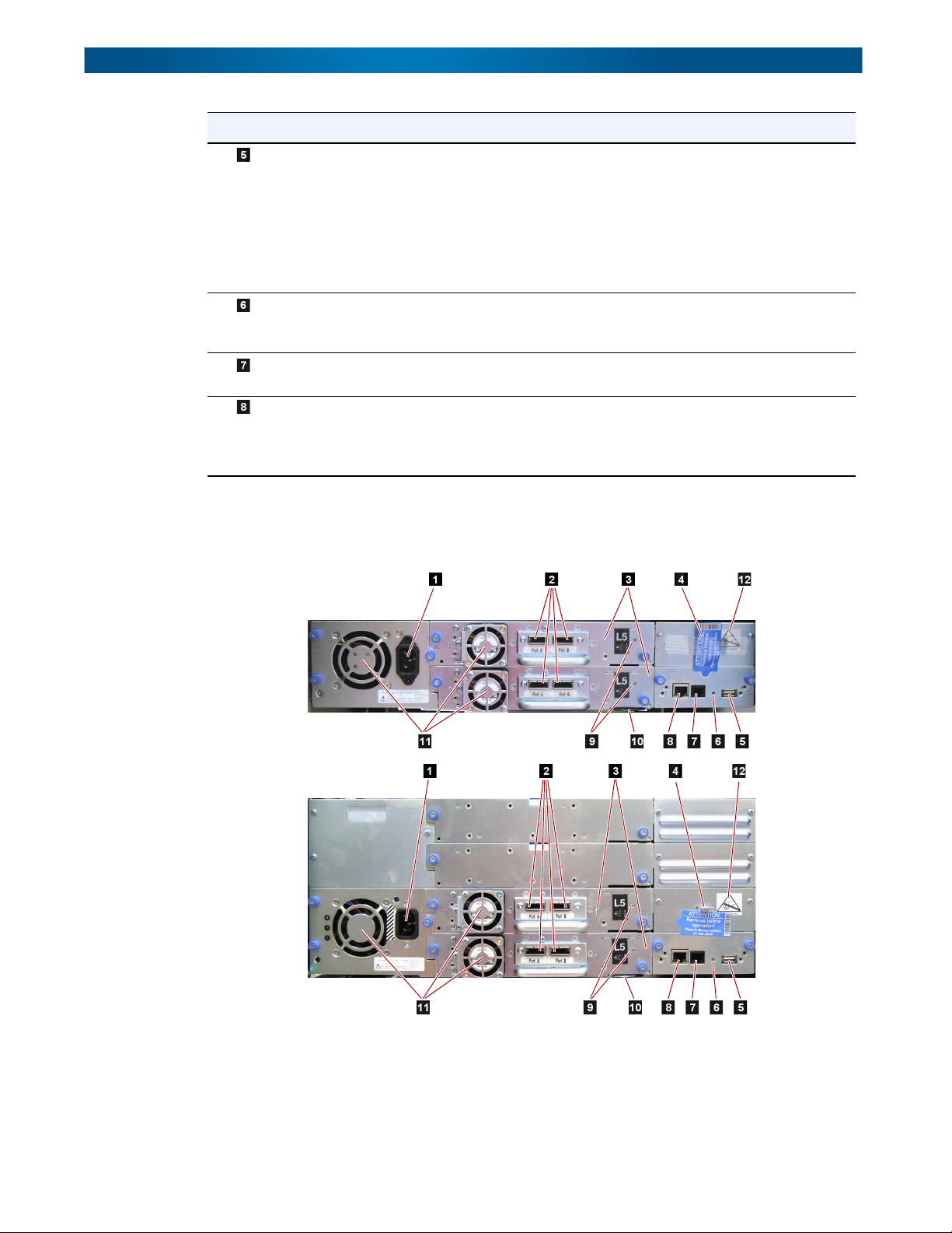
Rear Panel
These graphics and table illustrate the rear panel components:
10400367-001 04/2012 ©2012 Overland Storage, Inc. W 1-3
Page 15
NEO 200s/400s User Guide Physical Library
Number Item Description
Power connectors The libraries require a 110/220 volt AC power connection.
• The 2U library has one power supply.
• The 4U library has a minimum of one power supply, but has the
capability of adding a redundant power supply.
Host interface connectors The library has one or more of the following host interface
connectors on the drive sled:
• SFF-8088 mini-SAS connector
• Fibre Channel connector
Tape drive sled This library supports the Ultrium 4 and Ultrium 5 tape drives. The
tape drive in the library is packaged in a container called a drive
sled. Drive sleds come in a full high or Half-Height configuration.
The drive sled is a customer replaceable unit (CRU), and is hotpluggable, which is designed for easy removal and replacement.
Shipping lock and label
storage location
The shipping lock, which secures the accessor during shipping,
and associated label are stored on the rear panel of the library for
future use. See Removing and Storing the Shipping Lock.
CAUTION: The shipping lock must be removed before
powering ON the library to allow the accessor to
function properly.
USB port Used to save/restore library configuration information on a USB
device.
Library Control Board
(LCC) LED
An LED showing the status of the Library Control Board. The LED
flashing (1 flash per second) is normal operation.
Serial port This port is used to communicate serially with the library using an
RJ-11 connector. For use by Overland service personnel.
Ethernet port This port is used to connect the library to a network.
• 10/100 Link LED
• Description: Green; indicates link integrity
• Flashing: Network synchronization/negotiation
• Steady (On): Good connection
• Off: No connection between NIC and hub
• Activity LED
• Description: Amber; indicates port traffic
• Flashing: Network traffic present
• Steady (On): Heavy network traffic
• Off: No traffic
Tape drive LED This LED indicates the current status of the drive. When the LED
is green, it indicates normal drive activity.
Machine type, Model
number, and Serial
Number pull-out label
The machine type, model number and serial number of the library
are located on this pull-out label. This serial number is the
number that links the library to your warranty.
Fan vents These vents allow air to escape from the power supply and tape
drive sled.
ESD label The Electrostatic Discharge label is a reminder that some of the
components of this library are susceptible to electrostatic
discharge. See the “Preface.”
10400367-001 04/2012 ©2012 Overland Storage, Inc. W 1-4
Page 16

NEO 200s/400s User Guide Networking
Bar Code Reader
The bar code reader is an integral part of the library accessor. The bar code reader reads
each cartridge bar code label that identify the types of cartridge magazines and tape drive
installed in the library and provides inventory feedback to the host application, Operator
Control Panel, and Web User Interface. The library stores the customized inventory data in
memory. Library firmware supports a 6 or 8-character volume serial number (VOLSER) on
the bar code label on the tape cartridge.
Networking
This section covers the network supported features and options.
Supported Internet Protocols
The NEO 200s/400s supports the following Internet protocols:
• IPv4
• IPv6
To learn more about IPv4, visit http://www.iana.org/. To learn more about IPv6, visit
http://www.ipv6.org/.
Simple Network Management Protocol (SNMP) Messaging
Occasionally, the library may encounter a situation that you want to know about, such as
an open magazine or a fault that causes the library to stop. The library provides a standard
TCP/IP protocol called Simple Network Management Protocol (SNMP) to send alerts about
conditions (such as need for operator intervention) over a TCP/IP LAN network to an SNMP
monitoring station. These alerts are called SNMP traps. Using the information supplied in
each SNMP trap, the monitoring station (together with customer-supplied software) can
alert operations personnel of possible problems or operator interventions that occur.
SNMP Traps
SNMP Traps are alerts or status messages that can be collected, monitored and used to
proactively manage attached libraries using SNMP protocol with the SNMP monitoring
stations. In summary, each trap provides the following information:
• Product Identification such as product name, description, manufacturer, model
number, firmware level, and the URL for which the trap is designated.
• Product Status such as the severity of the trap, status (current and previous), and
the time the trap occurred.
• Library State (physical device status) such as identification and status of devices
that are monitored. In the case of the library, it would include enclosure, power
supply, controller, magazine status, drive count, cartridge slot count, and Mail Slot
count. Also included would be certain library statistics, and where appropriate, the
fault FSC (fault symptom code) including the severity and description of that fault.
• Drive Status such as the identification of each drive in the library, firmware level,
serial number, and other address and status information.
• Trap Definitions such as library status change, open magazine, Mail Slot accessed,
hard fault information, drive cleaning requests, excessive retries, and library
returning to normal operations.
10400367-001 04/2012 ©2012 Overland Storage, Inc. W 1-5
Page 17
NEO 200s/400s User Guide Networking
• SNMP MIBs: The library's Management Information Base (MIB) contains units of
information that specifically describe an aspect of the system, such as the system
name, hardware number, or communications configuration. Status and error data is
also gathered by MIBs and sent to one or more IP addresses defined during the SNMP
configuration operation. Download the SNMP MIB file for this library from
http://docs.overlandstorage.com/neo.
SNMP Status Events
This table provides information about SNMP events and the related Trap ID.
Event
Status Change 1 Library status has changed.
Door Open 2 Library door has been opened.
Mail Slot Accessed 3 Library I/O Station has been accessed.
Fault Posted 4 Library has posted a hard fault/error.
Request Drive Clean 5 Drive has requested a clean.
Drive Error 6 Drive has reported an error.
Loader Retries Excessive 7 Library has reported excessive load retries.
Loader OK 8 Library has resumed normal operations.
Account Password Change 9 Account password in the library has changed.
Configuration Change 10 Library or drive configuration has changed.
Library Login 11 Someone has logged into the library via the Web User
Library Logout 12 Someone has logged out of the library via the Web User
Network Time Protocol (NTP)
NTP is an Internet standard protocol that assures accurate synchronization of computer
clock times in a network of computers. Running as a continuous background client program
on a computer, NTP sends periodic time requests to a server, obtaining server time stamps,
and using them to adjust the client's clock.
Trap ID
Definition
Interface.
Interface.
Maximum Library Storage Capacity and Data Transfer Rate
Maximum library storage capacity and maximum data transfer rates are as follows:
Tape Drive Model Host Interface
Ultrium 5 Half-Height drives 8 Gb/s Fibre Channel – single port
6 Gb/s SAS
Ultrium 4 Half-Height V2 drives 8Gb/s Fibre Channel
6GB/s SAS
10400367-001 04/2012 ©2012 Overland Storage, Inc. W 1-6
– dual port
– single port
– dual port
Page 18

NEO 200s/400s User Guide Ultrium Tape Drives
Characteristic 2U Library Specification 4U Library Specification
Maximum storage
capacity
Cartridges
Maximum storage
capacity
Cartridges
Sustained native data
transfer rate
– Ultrium 5 Data
– Ultrium 4 Data
Ultrium Tape Drives
The NEO 200s/400s tape libraries support the Ultrium 4 and Ultrium 5 half-height tape
drives.
Each tape drive in the library is packaged in a container called a drive sled. The drive sled
is a customer replaceable unit (CRU), and is designed for quick removal and replacement of
a tape drive.
Both half-height tape drives either support two SAS SFF-8088 connectors that are
compatible with SAS-1 cables, or one LC Fibre Channel connector.
• 24 data cartridges
•Native: 36 TB
•Compressed: 72 TB
(2:1 compression)
• 24 data cartridges
• Native: 19.2 TB
• Compressed: 38.4 TB
(2:1 compression)
• LTO 5 Half-Height: 140 MB/s
• LTO 4 Half-Height: 120 MB/s
• 48 data cartridges
•Native: 72 TB
• Compressed: 144 TB
(2:1 compression)
• 48 data cartridges
•Native: 38.4 TB
• Compressed: 75.2 TB
(2:1 compression)
NOTE: LTO-4 and LTO-5 SAS and Fibre Channel drives are allowed in the same physical and
logical library but it is not recommended.
Speed Matching
To improve system performance, the Ultrium 4 and Ultrium 5 tape drives use a technique
called speed matching to dynamically adjust its native (uncompressed) data rate to the
slower data rate of the attached server.
Channel Calibration
The channel calibration feature of the Ultrium 4 and Ultrium 5 tape drives customizes each
read/write data channel for optimum performance. The customization enables
compensation for variations in the recording channel transfer function, media
characteristics, and read/write head characteristics.
Power Management
The Ultrium 4 and Ultrium 5 tape drives feature a power management function that
controls the drive's electronics so that part of the electronics completely turn OFF when
circuit functions are not needed for the drive's operation.
10400367-001 04/2012 ©2012 Overland Storage, Inc. W 1-7
Page 19
NEO 200s/400s User Guide Media
Media
The media used by NEO 200s/400s tape libraries are Ultrium Tape Cartridges that provide
up to 1500 GB native capacity (up to 3000 GB with 2:1 hardware data compression) for
Ultrium 5 tape drives and 800 GB native capacity (up to 1600 GB with 2:1 hardware data
compression) for Ultrium 4 tape drives.
LTO Ultrium Data Cartridges
Ultrium
Tape Drive
Ultrium 5 Read/Write Read/Write Read only – –
Ultrium 4 – Read/Write Read/Write Read only –
Ultrium 3 – – Read/Write Read/Write Read only
Ultrium 2 – – – Read/Write Read/Write
Ultrium 1 ––––Read/Write
1500 GB
(Ultrium 5)
800 GB
(Ultrium 4)
400 GB
(Ultrium 3)
200GB
(Ultrium 2)
100GB
(Ultrium 1)
For more detailed information, see Chapter 6, “Media.”
10400367-001 04/2012 ©2012 Overland Storage, Inc. W 1-8
Page 20
Chapter 2
User Interfaces
The library has a local interface (Operator Control Panel), and a remote interface accessed
via a web browser (Web User Interface).
The Operator Control Panel is located on the front of the library and allows users to work
locally on the library. The Web User Interface allows users and administrators to view and
perform some library functions from remote sites.
The Web User Interface is implemented as a Java Applet that runs in a web browser from
any PC on the network. The Java Applet requires that Java 1.5.0 or higher be installed on
your host computer for full functionality, and is best viewed using Internet Explorer 6.0 or
higher. Internet Explorer 7.0 or higher is required for IPv6.
Topics in User Interfaces:
• Operator Control Panel
• Web User Interface
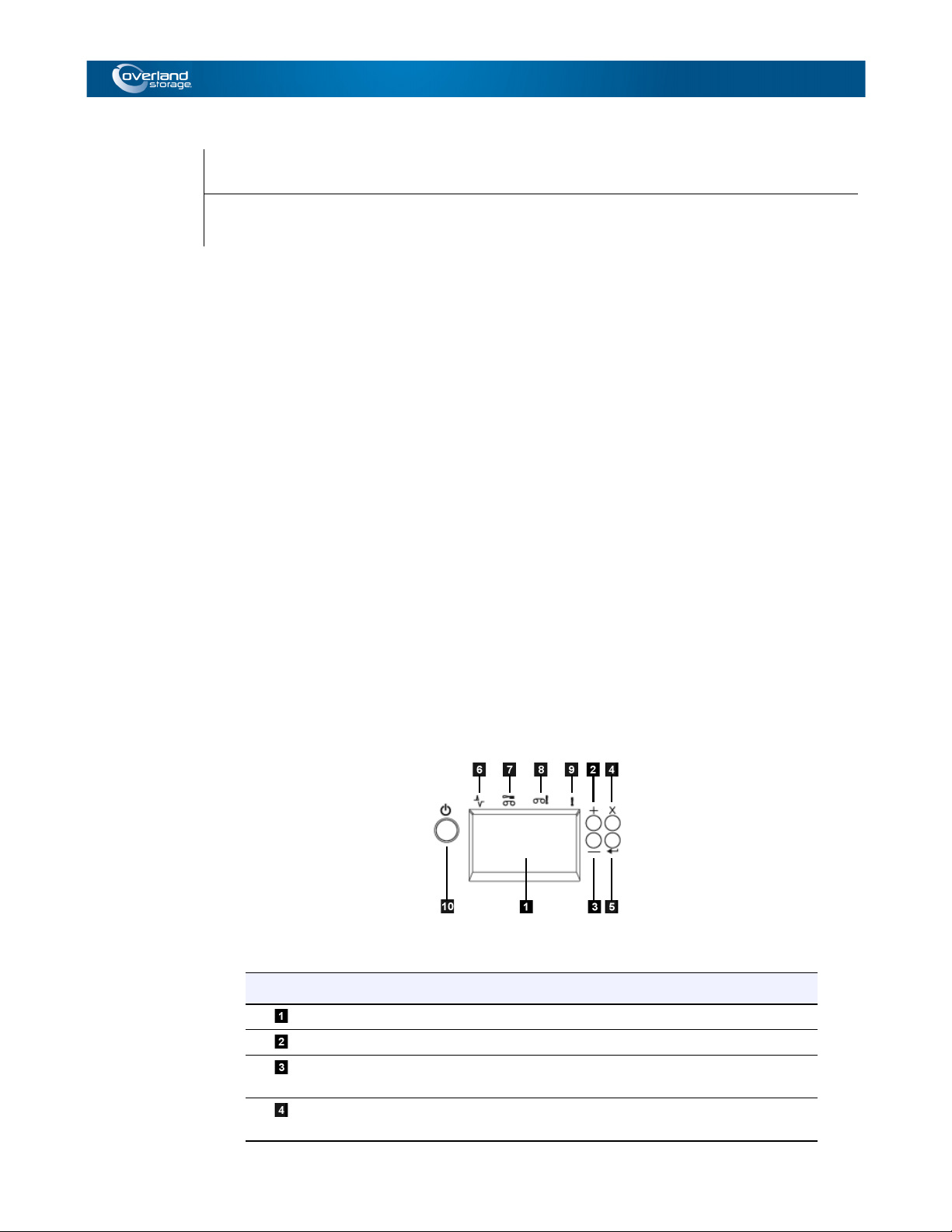
Operator Control Panel
The Operator Control Panel is located on the front bezel of the library. The Operator
Control Panel displays library information and menu commands used to execute library
management functions in response to the Control Keys (buttons) located on the right of the
LCD display.
Operator Control Panel component descriptions:
Number Component Description
LCD display 16-character LCD graphic display
UP (+) Button used to navigate upward (^) through the menu items
DOWN (–) Button used to navigate downward (V) through the menu
CANCEL (X) Button used to cancel a user action and return to the last
items
menu item
10400367-001 04/2012 ©2012 Overland Storage, Inc. W 2-1
Page 21
NEO 200s/400s User Guide Operator Control Panel
Number Component Description
SELECT ( ) Button used to display a submenu or to select a user action
Ready/Activity
LED
Clean Drive LED Amber LED lit when the drive needs cleaning. The LED turns
Attention LED Amber LED lit when a cartridge is bad, marginal, or invalid.
Error LED Amber LED lit when there is an unrecoverable library or drive
Power ON/OFF If the library is OFF, press the button for no more than one
Green LED lit when the unit is powered ON. The LED flashes
when there is any library activity or the library is offline.
OFF after the drive is cleaned successfully.
The LED turns OFF when the media is removed from the
drive. The LED may also be lit when there is a power supply
problem.
failure. The corresponding error message appears on the
LCD display.
second to start the POST process and power the library ON.
If the library is ON, pressing this button for 4 seconds will
initiate a controlled power down of the library (soft landing).
The following operations will take place before the library
shuts down completely:
• The display indicates with an appropriate message that
the shutdown is in progress.
• The library controller finishes all ongoing library and drive
activities.
• The accessor is moved to its home position.
• The library controller switches OFF the power supply's
secondary side.
NOTE: The shutdown process may be aborted by releasing
the button before 4 seconds has passed.
The Operator Control Panel operates in two basic modes:
• User Interaction mode – Mode employed when a user is pushing keys on the
Operator Control Panel.
• System Driven mode – Normal mode of operation where the Operator Control
Panel displays status in response to commands issued from the drive's internal
interface.
When an Operator Control Panel key is pressed and released, the Operator Control Panel
automatically transitions to User Interaction mode. User Interaction mode will continue
until 3 minutes after a user stops pushing keys, or the requested accessor action stops,
whichever is longer, then the Operator Control Panel returns to System Driven mode.
If necessary, the Operator Control Panel will automatically transition to System Driven
mode. When this occurs, the library remembers what the user was doing before the display
mode changed. Therefore the next button pressed only transitions the Operator Control
Panel to the User Interaction mode from the System Driven mode.
Any operational conflict between commands received over the host interface or the Web
User Interface and those entered via the Operator Control Panel are avoided with a
reservation mechanism on a first-come, first-served basis. Operator Control Panel
commands are canceled by an Operator Control Panel logout or timeout.
10400367-001 04/2012 ©2012 Overland Storage, Inc. W 2-2
Page 22
NEO 200s/400s User Guide Operator Control Panel
Library firmware will not allow a user to select an impossible request. Those situations will
include, but are not limited to:
• Moving a cartridge from any source to a position occupied by another cartridge
• Moving a cartridge from an empty cartridge position
• Loading a cartridge from any source to a full drive
• Unloading a cartridge from an empty drive
Any error detected by the library or drive controller and not recoverable through
predetermined firmware algorithms is considered fatal. When an error occurs, an error code
is displayed on the Operator Control Panel display and the error LED is ON. The error code
remains on the Operator Control Panel until a key is pressed, which causes the Operator
Control Panel to return to the Home Screen. Numeric error codes are used for
unrecoverable fatal errors, otherwise text status messages are displayed.
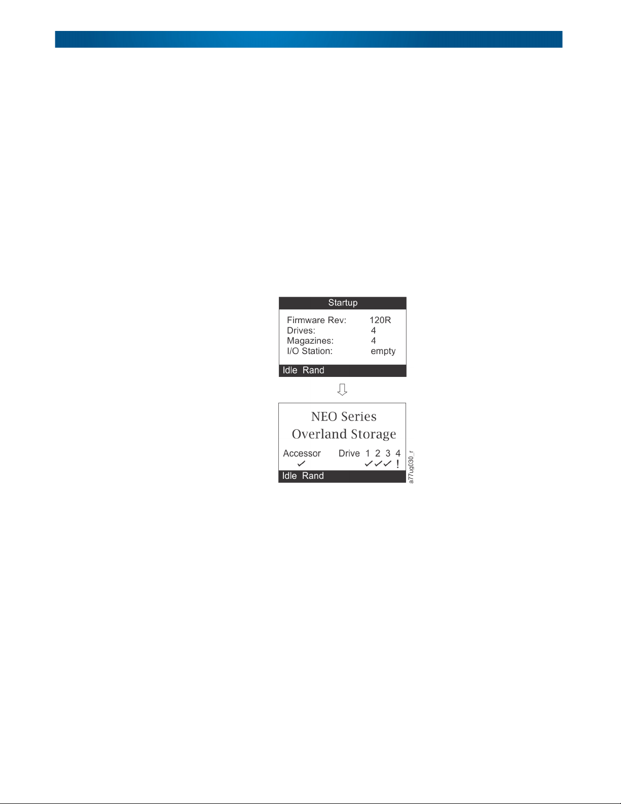
When the library powers ON or resets, it goes through several internally controlled
initialization processes, called the Power-On-Self-Test (POST).When the POST is finished,
the library displays the Startup screen, then the Home screen.
The Startup screen is the first screen that appears after powering ON the library. It
contains the following information:
• Firmware Rev: the current level of library firmware
• Drives: the total number of drives that the library can support
• Magazines: the total number of magazines in the library
• I/O Station: the current status of the Mail Slot
Front Panel LEDs
All LEDs are updated during power ON and reset sequences. Upon power ON or software
reset, the library illuminates all LEDs as soon as POST allows. When initialization starts,
all LEDs are extinguished and the Ready/Activity LED flashes at a rate of approximately
one second per cycle. When the mechanical initialization is complete, the Ready/Activity
LED will stop flashing and be constantly illuminated.
If a library failure occurs, the Ready/Activity LED turns OFF and the Error LED turns ON.
The Operator Control Panel also displays an appropriate error code to help identify the
failure.
The following are additional operational details of LEDs:
10400367-001 04/2012 ©2012 Overland Storage, Inc. W 2-3
Page 23
NEO 200s/400s User Guide Operator Control Panel
• The Ready/Activity LED ( ) is illuminated any time the unit is powered ON and
functional. The Ready/Activity LED blinks whenever there is library or drive activity.
This LED will also blink when the unit is OFFLINE.
• The Clean LED ( ) is illuminated when either a cleaning requested or a cleaning
required flag has been issued by the drive. The LED is turned off after a successful
drive cleaning operation.
• The Attention LED ( ) indicates one of the following conditions.
Problem Action Required
Bad media 1. Go to Monitor > Inventory to locate the defective
cartridge.
2. Move the defective cartridge to the Mail Slot. (Operator
Control Panel:
3. Open the Mail Slot to remove the defective cartridge.
(Operator Control Panel:
Drive sled issues Do one of the following:
•Install a different drive sled.
• Modify or resubmit Logical Library setting (Operator Control
Panel:
Configure > Logical Libraries or Web User
Interface:
• Restore defaults (Operator Control Panel:
Restore Defaults
Library > Restore Defaults
Redundant power supply failed Complete the following steps:
1. Replace the failed power supply.
2. Cycle library power.
Power supply fan failure Replace the power supply.
Control > Move Cartridges).
Control > Open I/O).
Configure Library > Logical Libraries).
Configure >
or Web User Interface: Configure
).
• The Error LED ( ) turns ON when there is an unrecoverable drive or library failure.
Input Modes
There are several ways to enter values in the different menu items. These values are
selectable predefined values, toggle values (for example, ON/OFF) and numerical values
like network addresses.
Selecting Predefined Values
1. To set the predefined values, press the SELECT button to select the menu item.
2. Using the UP and DOWN buttons, select one of the various predefined values for
3. As soon as the Operator Control Panel display shows the correct value, press the
An error message is displayed on the screen and the LED remains ON until the error
state is resolved.
NOTE: From the Operator Control Panel, run Service > Library Verify. If Library Verify runs
without error, the Error LED turns off. If the error persists, recycle the power.
that item.
SELECT key to apply the value.
10400367-001 04/2012 ©2012 Overland Storage, Inc. W 2-4
Page 24

NEO 200s/400s User Guide Web User Interface
Toggling Values
Toggle values are used to switch between two different states like ON and OFF.
1. After navigating to the menu item, press the SELECT key to select the menu item.
2. Using the UP and DOWN keys, select one of the various predefined states for that
item.
3. Press the SELECT key to apply the new state.
Entering Numerical Values
Numerical values are needed for network addresses, password entries, and other
configuration entries.
1. After navigating to the menu item, the current value is displayed and the cursor
highlights the first digit of the value that can be changed.
2. For each digit to be changed in the value:
a. Use UP and DOWN to increment or decrement the digit.
b. Press SELECT to highlight the next editable digit.
3. Press SELECT at the last digit to apply the complete entry (or press CANCEL to
cancel the whole edit process and maintain the original value).
Web User Interface
Many of the same operations performed from the Operator Control Panel can also be
performed remotely using the Web User Interface.
The Web User Interface lets you monitor and control your library from any terminal
connected to your network or through the World Wide Web (WWW). The Web User
Interface hosts a dedicated, protected Internet site that displays a graphical representation
of your library.
For static IP Addresses only: After establishing a connection to the library, open any HTML
browser and enter the IP address of the library. To configure the Web User Interface, you
must first set the IP address using the Operator Control Panel. Refer to “Configuring
Network Settings” on page 4-13 or “Configuring Network Settings” on page 4-23.
The Web User Interface Java Applet requires Java 1.5.0 or higher be installed on your host
computer for full functionality, and is best viewed using Internet Explorer 6.0 or higher.
Internet Explorer 7.0 or higher is required for IPv6. If your computer does not have Java
installed or you need to upgrade your installation, download the latest version of the Java
Runtime Environment (JRE) for your platform from http://www.java.com/ and follow the
instructions provided to enable and configure the Java Runtime Environment for your
browser.
The Web User Interface can also be used to update the library and drive firmware, and to
download error logs, drive dumps, and other library data from the library.
Before the NEO 200s/400s can be managed over a network using the Web User Interface,
you must set up the initial network configuration of the library using the Operator Control
Panel.
10400367-001 04/2012 ©2012 Overland Storage, Inc. W 2-5
Page 25
NEO 200s/400s User Guide Web User Interface
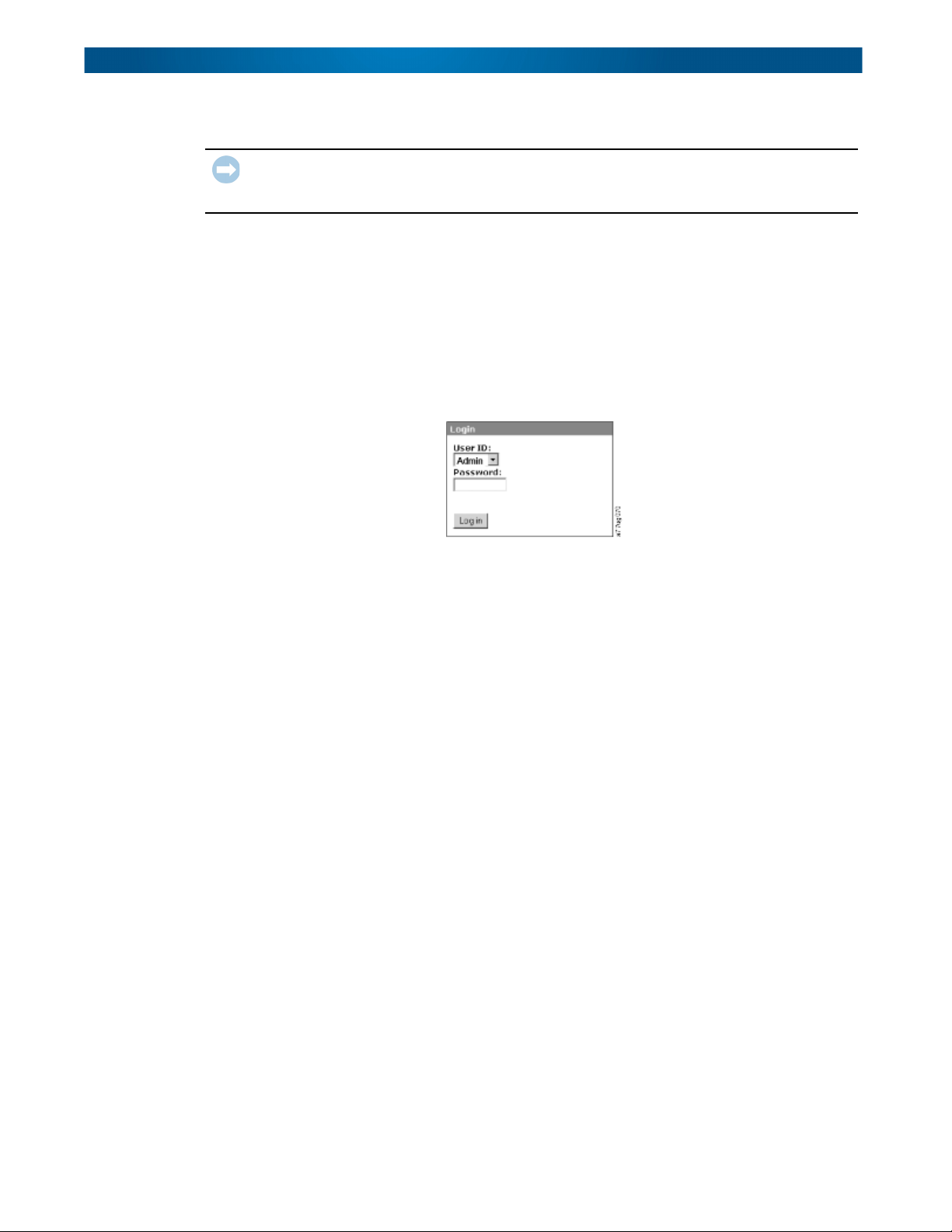
Login
IMPORTANT: Some options of the Web User Interface take the library OFFLINE. This inactive
mode can interfere with host-based application software, causing data loss. Make sure the
library is idle before attempting to perform any remote operations that will take the library OFFLINE.
To login, select the Role type and enter the correct password. There are four levels of access:
• User – Normal user level. The User only has access to Monitor Library menus.
• Superuser – The Superuser has access to the Monitor Library and Manage Library
sections.
• Admin – The Admin user level has access to all menus except those restricted to
Service only.
• Service – The Service personnel user level access to this level is for Overland
Authorized Service personnel only. Service personnel have access to all menus.
Use the default password for logging in as an Admin user is secure.
NOTE: Passwords are case-sensitive.
Each level affects which areas you have access to and what actions you can initiate from
those areas.
For DHCP, use the Operator Control Panel to determine the IP Address assigned to your
library. Navigate to Monitor > Library > Identity. Scroll down to IP Address and make note
of the address. Enter the IP Address in your internet browser address field to access your
library with the Web User Interface.
For IPv4 or Dual Stack IPv4 + IPv6, enter your library's static IP Address using the 0.0.0.0
format (four octets).
For IPv6, enter your library's static IP Address or Router Assigned IP Address using the
following format: http://[0:0:0:0:0:0:0:0]. To determine your Router Assigned IP Address,
navigate to Monitor > Library > Network on the Operator Control Panel. For the IPv6 Router
Assigned Addresses to be displayed on the Operator Control Panel, the Network must be
configured to IPv6 Only and the Stateless Autoconfig on the must be set to ON.
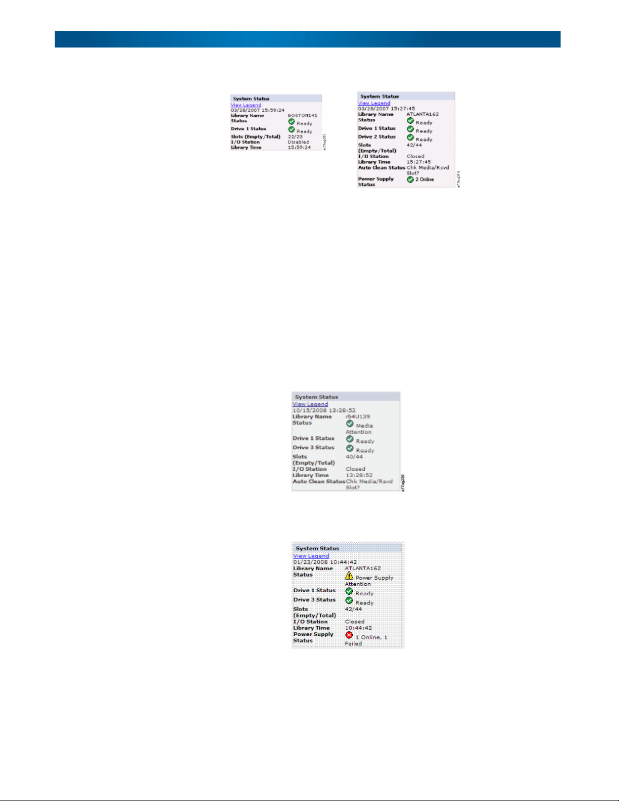
System Status
The System Status screen is always present after login giving current status of the library.
10400367-001 04/2012 ©2012 Overland Storage, Inc. W 2-6
Page 26
NEO 200s/400s User Guide Web User Interface
NEO 200s NEO 400s
Status icons indicate the following conditions.
• The green check mark indicates that the library is fully operational and that no user
intervention is required.
• The yellow exclamation point indicates that user intervention is necessary, but that
the library is still capable of performing operations. This condition can be caused by a
media, library, redundant power supply, power supply fan, or a drive sled problem. To
determine which, view the System Status screen.
• The red X indicates that user intervention is required and that the library is not
capable of performing operations.
• If Auto Clean is enabled and a cleaning cartridge is not present, or if a cleaning
cartridge is present, but not in a reserved slot, Auto Clean status will show Chk
Media/Rsvd Slot? and Status will show a green check mark and the words Media
Attention.
The Power Supply Status will only appear if redundant power is being utilized with a 4U
library. If a redundant power supply fails, the System Status screen appears.
NOTE: The Green LED will be ON on both power supplies. If one Green LEDs is not ON, replace
10400367-001 04/2012 ©2012 Overland Storage, Inc. W 2-7
that power supply.
Page 27

NEO 200s/400s User Guide Web User Interface
Web User Interface Help Pages
Each screen on the Web User Interface has an associated Help page. To access a Help page,
click Help in the upper right corner of the screen. A new web page will open. Using the left
navigation pane, select the desired Help page. To close the Help page, click the red
X in the
upper right corner of the screen.
Logging out of the Web User Interface
To log out of the Web User Interface, click Logout in the upper right corner of the current
screen.
NOTE: If you click the X in the upper right corner of your internet browser window, the screen will
close but you will not be logged out of the Web User Interface.
10400367-001 04/2012 ©2012 Overland Storage, Inc. W 2-8
Page 28

Chapter 3
Installation Planning
Before installing your library, take time to review the following information.
Topics in Installation Planning:
• Determining Number of Logical Libraries
• Library Partitioning and Element Addressing
• Using Persistent Binding
• Logical Unit Number (LUN) Scanning
• Host Interfaces
Determining Number of Logical Libraries
You can partition the library into as many logical libraries as there are drives in the library.
Basic Guidelines
• Each logical library must contain at least one drive.
• A library configuration of exactly one logical library equals the entire physical library.
• The library issues a warning to the user if media is moved across logical libraries.
Library Sharing
The library's default configuration allows a single application to operate the library through
a single control path. Often, it is advantageous to be able to share a single library between
heterogeneous (dissimilar) or homogeneous (similar) applications. Some applications (and
some servers) do not allow for sharing a library between systems. Configurations can be
created that enable the library to process commands from multiple heterogeneous
applications and multiple homogeneous applications.
Configure the library so that it is partitioned into separate logical libraries that
independently communicate with separate applications through separate control paths.
This configuration requires no special capabilities from the server or application.
Library Partitioning and Element Addressing
A 2U or 4U library system containing more than one drive can be configured into separate
logical libraries (create partitions). For the 2U library, one to two partitions are available.
For the 4U library, it is possible to configure one to four partitions. Each library must
contain at least one drive per partition.
10400367-001 04/2012 ©2012 Overland Storage, Inc. W 3-1
Page 29
NEO 200s/400s User Guide Library Partitioning and Element Addressing
Partitioning of 2U Libraries
When two half-height drives are installed in a 2U library, the library firmware supports
partitioning. The first partition contains the first magazine and the first drive (called
Drive 1). The second partition contains the second magazine and the second drive (called
Drive 2). The Mail Slot (if configured as Mail Slot) is shared.
Partitioning of 4U Libraries
When one or more half-height drives are added to a 4U library, the library firmware
supports partitioning. The first half-height drive in the bottom position is called Drive 1.
The half-height drive above it is called Drive 2. And so forth up to four drives.
Mixing of Drives
The libraries support a mix of Ultrium 4 and 5 drives in the same physical library and the
same logical library.
NOTE: While the libraries also support a mix of SAS and Fibre Channel drives in the same physical
library and same logical library, mixing drive interface types in the same logical library is
not recommended.
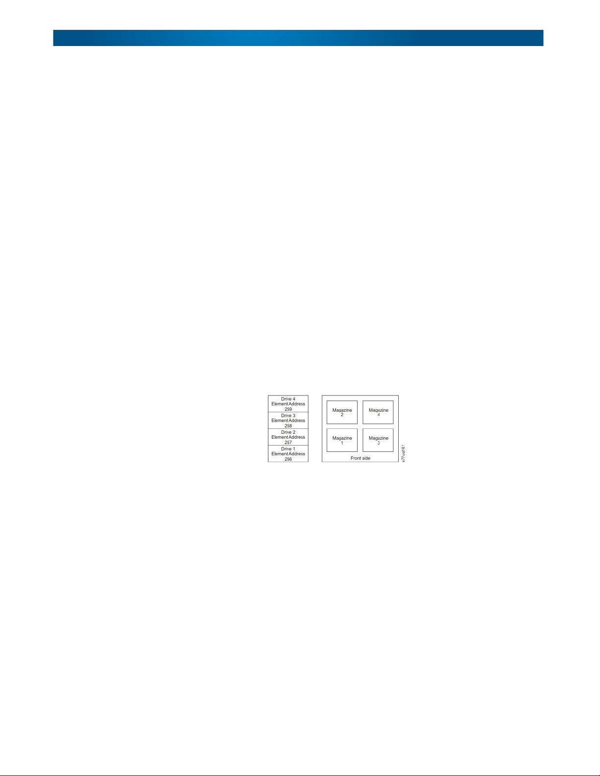
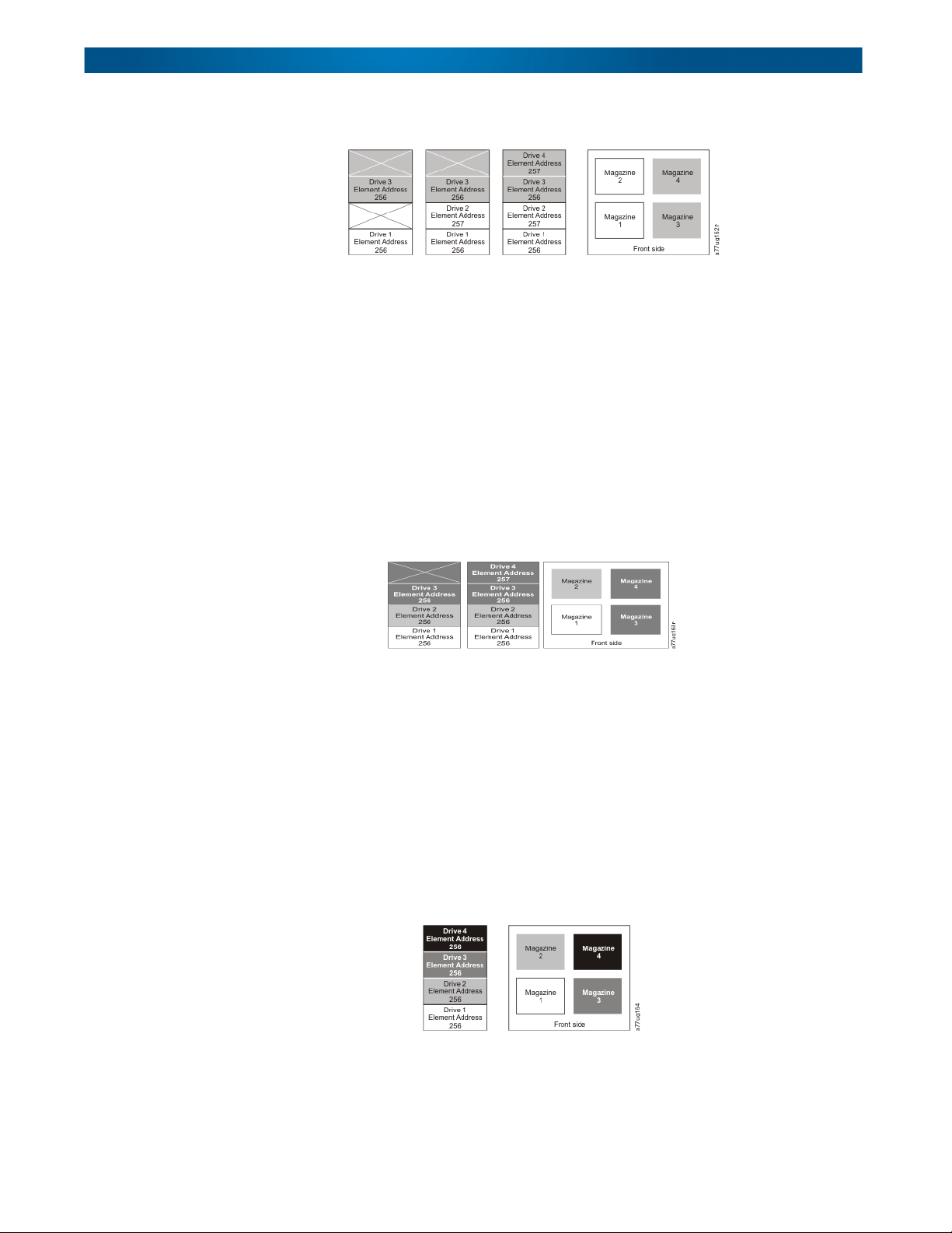
Configuration of a One-Partition System
A single-partition system configured for a 4U library contains any and all drives present in
any drive positions, and all four magazines. When configured with one logical partition, the
Element Address assignments will be as follows for the Data Transfer (Drive) Element
(DTE) and the Storage Elements (STE):
DTE assignments:
STE assignments:
• Logical Library 1: Slot 1 through 23, 4096 (0x1000) through 4118 (0x1016).
Configuration of a Two-Partition System
A two-partition system must have at least two drives installed. One drive must be installed
in either drive position 1 or drive position 2, and another drive must be installed in either
drive position 3 or drive position 4. Partition 1 contains any drives in drive position 1 and
drive position 2. Partition 1 will also contain magazine 1 and magazine 2. Partition 2
contains any drives in drive position 3 and drive position 4. Partition 2 will also contain
magazine 3 and magazine 4.
When configured with two logical partitions, the Element Address assignments will be as
follows:
10400367-001 04/2012 ©2012 Overland Storage, Inc. W 3-2
Page 30
NEO 200s/400s User Guide Library Partitioning and Element Addressing
DTE assignments:
STE assignments:
• Logical Library 1: Slot 1 through slot 21, 4096 (x1000) through 4116 (0x1014)
• Logical Library 2: Slot 22 through slot 45, 4096 (x1000) through 4019 (0x1017)
Configuration of a Three-Partition System
A three-partition system must have at least three drives installed. A drive must be installed
in drive position 1, another drive must be installed in drive position 2, and another drive
must be installed in either drive position 3 or drive position 4. Partition 1 will contain the
first drive and the first magazine. Partition 2 will contain the second drive and the second
magazine. Partition 3 will contain any drives in drive position 3 and drive position 4.
Partition 3 will also contain magazine 3 and magazine 4.
DTE assignments:
STE assignments:
• Logical Library 1: Slot 1 through slot 9, 4096 (x1000) through 4104 (0x1008)
• Logical Library 2: Slot 10 through slot 21, 4096 (x1000) through 4107 (0x100B)
• Logical Library 3: Slot 22 through slot 45, 4096 (x1000) through 4119 (0x1017)
Configuration of a Four-Partition System
A four partition system must have four drives. Each partition contains one drive and one
magazine. When configured with four logical partitions, the Element Address assignments
will be as follows:
DTE assignments:
STE assignments:
• Logical Library 1: Slot 1 through slot 9, 4096 (x1000) through 4104 (0x1008)
• Logical Library 2: Slot 10 through slot 21, 4096 (x1000) through 4107 (0x100B)
• Logical Library 3: Slot 22 through slot 33, 4096 (x1000) through 4107 (0x100B)
10400367-001 04/2012 ©2012 Overland Storage, Inc. W 3-3
Page 31

NEO 200s/400s User Guide Using Persistent Binding
• Logical Library 4: Slot 34 through slot 45, 4096 (x1000) through 4107 (0x100B)
Using Persistent Binding
Persist ent bi nding is an HBA funct ion th at allows a subset of discovered target s to be bound
between a server and device. Consult your HBA user guide for further information.
Logical Unit Number (LUN) Scanning
The library uses a single SCSI or Loop ID per drive and dual LUNs to control the tape drive
(LUN 0) and library accessor (LUN 1). The library requires a Host Bus Adapter (HBA) that
supports LUN scanning. If it is not enabled, your host system will not scan beyond LUN 0
and will fail to discover the library. It will only see the tape drive.
NOTE: Some HBAs, such as RAID controllers, do not support LUN scanning.
Host Interfaces
The 2U library and the 4U library can be attached to servers using the following interfaces:
• Serial Attached SCSI (SAS)
• Fibre Channel (FC)
SAS Interface
A drive sled with a SAS interface can be linked directly to controllers. SAS is a performance
improvement over traditional SCSI because SAS enables multiple devices (up to 128) of
different sizes and types to be connected simultaneously with thinner and longer cables; its
full-duplex signal transmission supports up to 6.0 Gb/s. The SFF-8088 SAS connectors on
the Ultrium 5 tape drives are compatible with SAS-1 or SAS-2 cables. The SFF-8088 SAS
connectors on the Ultrium 4 tape drives are compatible with SAS-1 cables. In addition, all
SAS drives can be hot-plugged.
SAS drives will auto-negotiate speed. There are no configurable topologies thus no feature
switches associated with SAS. The SAS Ultrium 4 half-height drive sleds are single ported
and can only be attached to one host. LAN-free drive sharing is not supported. Ultrium 4
SAS drive sleds use the SFF-8088 connection at the drive sled end and SFF-8088 or SFF8470 at the host adapter end.
Drive Type SAS Support FC Support
Ultrium 4 Half-Height X X
Ultrium 5 Half-Height X X
Fibre Channel Interface
Fibre Channel allows for an active intelligent interconnection scheme, called a Fabric, to
connect devices. Everything between the ports on Fibre Channel is called the Fabric. The
Fabric is most often a switch or series of switches that takes the responsibility for routing.
The library allows the selection of the following Fibre channel port behaviors:
10400367-001 04/2012 ©2012 Overland Storage, Inc. W 3-4
Page 32

NEO 200s/400s User Guide Host Interfaces
• LN Port: (default setting) – an automatic configuration that tries arbitrated loop first,
then switched fabric
• L Port – arbitrated loop
• N Port – point to point protocol in a switched fabric topology
Cables and Speeds
Ultrium 4 and Ultrium 5 Fibre Channel tape drives use LC duplex fiber optics cables.
The maximum distances that the library supports on a Fibre Channel link is determined by
the link speed, the type of fiber (50-micron or 62.5-micron), and the device to which the
library is attached.
If the library attaches to an HBA (Host Bus Adapter), refer to the distances that are
supported by the HBA. If the library attaches to a switch, the supported distances are:
• For a multi-mode 50-micron cable:
• 1-Gbit link speed = up to 500 m (1640 ft.)
• 2-Gbit link speed = up to 300 m (984 ft.)
• 4-Gbit link speed = up to 175 m (574 ft.)
• 8-Gbit link speed = up to 150 m (492 ft.)
• For a multi-mode 62.5-micron cable:
• 1-Gbit link speed = up to 300 m (984 ft.)
• 2-Gbit link speed = up to 90 m (295 ft.)
• 4-Gbit link speed = up to 50 m (164 ft.)
• 8-Gbit link speed = up to 21 m (68 ft.)
NOTE: Minimum distance for both 50 micron and 62.5 micron is 2 m (6 ft.).
Using Zoning to Isolate Devices and Enhance Security
For security reasons, it is important to limit the devices that a server or servers can
recognize or access. Also, some performance configurations and SAN configurations can
result in a device being seen multiple times from the same server. For example, if you have
two HBAs from the same server connected to an Ultrium Tape Drive in the library, the
drive will be detected and appear as two logical devices. That is, there will be two special
files for one physical device. Zoning can address these issues.
Zoning allows you to partition your SAN into logical groupings of devices so that each group
is isolated from the other and can only access the devices in its own group. Two types of
zoning exist: hardware zoning and software zoning. Hardware zoning is based on physical
fabric port number. Software zoning is defined with a World Wide Node Name (WWNN) or
World Wide Port Name (WWPN). While zoning can be reconfigured without causing an
outage, some zoning configurations can become complicated. The advantage of the library's
WWNN implementation is that you can avoid the exposure of introducing zoning errors
because you do not have to change the zoning configuration if a drive needs service or
replacement.
IMPORTANT: It is recommended that tape storage devices be connected on a separate HBA
from disk storage devices to avoid potential configuration incompatibilities.
10400367-001 04/2012 ©2012 Overland Storage, Inc. W 3-5
Page 33

NEO 200s/400s User Guide Host Interfaces
Fibre Channel Host Environment
The library is supported by a wide variety of servers (hosts), operating systems, and
adapters. These attachments can change throughout the product's life cycle. To determine
the latest supported attachments, visit the Overland NEO web site.
Sharing on a Storage Area Network
With Storage Area Network (SAN) components, the possibilities for connecting multiple
systems and multiple drives have increased. Not all software and systems are designed to
share drives. Before you install a drive that would allow two systems to share it, check that
the systems and their software support sharing. If your software does not support sharing,
note that Fibre Channel switches have a zoning capability to form a SAN partition. For
systems that do not cooperate, use zoning to prevent the systems from sharing the same
drive. You can remove zoned partitions as you upgrade software and system levels.
10400367-001 04/2012 ©2012 Overland Storage, Inc. W 3-6
Page 34

Chapter 4
Installation & Configuration
To install and configure a NEO 200s/400s library, perform the procedures in this chapter in
the order they are presented.
Topics in Installation & Configuration:
• Choosing a Location
• Installing in a Rack
• Configure Library Settings
• Configuring Your Library – Web User Interface
• Configuring Your Library – Operator Control Panel
• Preparing the Host
• Verifying the Connection
• Cartridge Magazines
• Populating the Library with Data Cartridges
• Inserting the Cleaning Cartridge
• Registering for Support Notification
Choosing a Location
Choose a location that meets the following criteria:
Criteria Definition
Room Temperature 16 to 32°C (60 to 90°F)
Power Source AC Power Voltage: 100 to 240 Vac. (4.0 to 1.5 A)
NOTE: The 4U library requires two separate power sources to
implement redundant power.
Line Frequency: 50 to 60 Hz
Place the library near an AC outlet. The AC power cord is the
product's main AC disconnect device and must be easily
accessible at all times. Two separate power sources must be
available for redundant power.
Air Quality The library should be placed in an area with minimal sources of
particulate contamination. Avoid areas near frequently used
doors and walkways, stacks of supplies that collect dust, printers,
and smoke-filled rooms. Excessive dust and debris can damage
cartridges and the tape drive.
10400367-001 04/2012 ©2012 Overland Storage, Inc. W 4-1
Page 35

NEO 200s/400s User Guide Installing in a Rack
Enter
Enter
Criteria Definition
Relative Humidity 15 to 80% non-condensing
Clearance • Back: Minimum of 15.4 cm (6 in.)
• Front: Minimum of 30.8 cm (12 in.)
• Sides: Minimum of 5 cm (2 in.)
Rack Requirements Standard 19-inch rack with:
• 2U (88.90 mm/3.5 in.) of clearance for a 2U library
• 4U (177.8 mm/7 in.) of clearance for a 4U library
Installing in a Rack
NOTE: If the temperature in the room where the library will be installed varies by 15° C (30° F)
from the room where the library was stored, allow the library to acclimate to the
surrounding environment for at least 12 hours before unpacking it from the shipping
container.
Register to Activate Your Warranty
It is essential that you activate your warranty. Technical and warranty support are not
available until the warranty is active:
1. Go to http://www.overlandstorage.com/ and select Service
& Support > My Products.
2. At the Site Login, enter your e-mail address and
password, and click GO.
3. Click Register New Product.
4. Fill in the information (including serial number)
and click Submit.
Your warranty certificate will be emailed to you. Follow the instructions included in the
email to complete the registration process.
Remove the Shipping Lock
WARNING: Due to the weight of the appliance, it is recommended that at least two people be
used to lift the unit out of the box to prevent injury.
AVERTISSEMENT: En raison du poids de l'appareil, il est recommande d'utiliser deux personnes au
moins pour soulever l'appareil hors de la boîte pour éviter les blessures.
IMPORTANT: The shipping lock, which prevents the library accessor from moving during
shipment, must be removed before the library is powered ON.
The shipping lock is held in place with a label and is located in the top center of the library.
After the shipping lock is removed, store it on the right side of the back panel for future use.
1. Using two people, remove the library from its box and set it on a secure surface.
10400367-001 04/2012 ©2012 Overland Storage, Inc. W 4-2
Page 36

NEO 200s/400s User Guide Installing in a Rack
2U (3.5 in.)
2. Remove blue securing label ().
3. Lift and remove the shipping lock ().
4. Store the shipping lock and blue label at the top right ( ) of the rear panel of the
library.
Slide the lock into the slot with the bottom of the lock showing below the slot. Press
the label over the flat part of the lock.
Rack Installation
The NEO 200s/400s libraries each come with a rack shelf kit for easy installation and
securing of the library into a 19-inch (EIA-310) rack.
IMPORTANT: Two-post telco-style or other racks less than 29 inches in depth will NOT support
this unit.
Install the Rack Rails
1. Determine the location in your rack for your library to be installed and, using a
pencil, mark the location on each vertical rail in your rack.
NOTE: A 2U library requires 2U (3.5 in.) of rack space. A 4U library requires 4U (7 in.) of rack
space.
10400367-001 04/2012 ©2012 Overland Storage, Inc. W 4-3
Page 37

NEO 200s/400s User Guide Installing in a Rack
Front View Rear View
& Two EIA units (2U)
needed for round
hole and square
hole rail
installation
Wide Gaps within
the EIA unit
Narrow Gaps
between EIA units
2. Ensuring that the flange on each rail points toward each other to form a shelf, secure
one rail to each side of the rack in your chosen rack location:
NOTE: Use the screws for your rack type (labeled for round holes or square holes) and a #2
Phillips screwdriver to install the rails.
a. Extend the rails to fit your particular rack depth.
The two alignment pins go into the first and second holes from the bottom of the
2U space. The extension sections should be at the rear.
b. With the large black screws, secure the front and back of each rail to the rack.
The screw securing the rack goes into the fourth hole from the bottom in the front
and the middle hole in the rear.
NOTE: The rails must be fastened with the bottom of the each rail parallel to floor and at the
same level.
Attach the Rail Brackets
1. Using the Torx wrench included in your shipment, remove the two screws ( ) noted
from both sides of the library.
Screw locations on the 4U library are similar.
10400367-001 04/2012 ©2012 Overland Storage, Inc. W 4-4
Page 38

NEO 200s/400s User Guide Installing in a Rack
M3 x 4
Previously Removed Screw
M3 x 6a with
“Donut”
“Donut”
2. Install the library rack anchor “donuts” ( ) on each side of your library using the M3
x 6 counter-sunk screws included in the rack kit.
3. Install the library mounting brackets ( ) as shown on each side of the 2U library
using the screw that was removed from your library and an additional M3 x 4
counter-sunk screw included in the rack kit.
The 4U rack anchors and mounting brackets are similar.
Insert the Library in Rack
WARNING: It is recommended that a mechanical lifter (or at least two people) be used to
raise and align the unit to prevent injury during installation. Use care when inserting or
removing a unit into or out of a rack to prevent the accidental tipping of the rack, causing damage
or personal injury.
AVERTISSEMENT: Afin d’éviter des blessures pendant l’installation, il est recommande d’utiliser un
monte-charge (ou au moins deux personnes) pour élever ou aligner l’appareil. Faites attention
lorsque vous insérez ou retirez l’appareil d’un support, pour empêcher le déversement accidentel
de la crémaillère causant des dommages et des blessures.
1. Using the mechanical lifter, position the library in front of the rack, aligned with the
rails.
2. Slide the library onto the rails until the mounting brackets are up against the
vertical rack rails.
The “donuts” on the side of the library should be under the side bump-out slots at the
rear of the rails.
3. Secure it to the rack with the captive screws.
Install Any Add-on Components
The NEO 200s/400s libraries are expandable and accept add-on components to enhance
10400367-001 04/2012 ©2012 Overland Storage, Inc. W 4-5
performance:
Page 39

NEO 200s/400s User Guide Installing in a Rack
- AC Power Socket
- SAS HBA Ports
- Ethernet Port
- Serial Port
- USB Connection
NEO 200s Library
NEO 400s Library
• Additional tape drives can be installed in the empty bays. On the NEO 400s, always install the
drives from the bottom up.
• Redundant (second) power supply is available for the NEO 400s.
Once the library is secure in the rack, the additional items should then be installed before
hooking up the system. Follow the instructions enclosed with each component.
Cable Attachment
CAUTION: It is recommended that you shut down and turn OFF the associated server. Turn
OFF all attached devices. Remove the power cables from the server and all attached
accessories. Failure to remove the power cords from these devices before connecting the host
interface cable could result in damage to the library.
All cabling, power connections, and cooling are located on the NEO rear panel.
10400367-001 04/2012 ©2012 Overland Storage, Inc. W 4-6
1. Attach one end of the host interface cable to the library:
• For a SAS connected library, attach one end of the SAS cable to Port A (left) SAS HBA ( ) on
the drive.
• For a Fibre Channel (FC) library, attach one end of the fibre cable to Port 0 (left) connector on
the drive (not shown).
2. Attach the other end of the host interface cable as follows:
• For a SAS library, connect the host interface cable to the host HBA, using a direct SFF-8088
connection, or an interposer as required. Unused SAS connectors do not need termination.
• For a Fibre Channel library, connect the fibre cable to the host or to a switch. If an SC-to-LC
interposer is required, refer to Installing a Fibre Channel Interposer.
Page 40

NEO 200s/400s User Guide Installing in a Rack
3. Plug the network Ethernet (management) cable into the Ethernet port on the
back panel of the library. If the Ethernet connection is directly attached to a server or
laptop, a crossover Ethernet cable may be required.
NOTE: It is the customer's responsibility to supply the crossover cable if one is required.
Installing a Fibre Channel Interposer
To install the FC interposer:
1. Connect the host SC fibre cable to the matching side of the interposer.
2. Connect the drive LC fibre side of the interposer to the drive/library.
Power Cord Attachment
WARNING: This device has more than one power cord. Disconnect ALL power supply cords
before servicing.
AVERTISSEMENT: Cet appareil a plus d’une cordon d’alimentation. Débranchez TOUTES les cordons
d’alimentation avant l’entretien.
1. Remove the protective label from the power receptacle on your library.
2. Plug one end of each power cord into each power supply connector on the back panel
of the library.
3. Plug the other end of each power cord into the nearest properly grounded power
outlet. Use separate power sources for each power supply for redundant power.
4. Turn ON the library using the Power button.
Check the Operator Control Panel display to make sure the library is receiving power.
If it is not, check the power connections and your power source. During the Power-On
Self Test (POST), all four LEDs are illuminated briefly, followed by a flashing Ready
LED. When the initialization sequence is complete, the Home screen is displayed.
10400367-001 04/2012 ©2012 Overland Storage, Inc. W 4-7
Page 41

NEO 200s/400s User Guide Configure Library Settings
Configure Library Settings
The library can be configured using the Web User Interface and/or the Operator Control
Panel. The recommended method for configuring your library is using the Web User
Interface. See “Configuring Your Library – Web User Interface” on page 4-8 and
“Configuring Your Library – Operator Control Panel” on page 4-19.
For complete detailed information on all of the functions available on the library using both
the Operator Control Panel and the Web User Interface, see Chapter 5, “Operations.”
Using Factory Defaults as Your Configuration
The table below shows the main default library settings. If you wish to use the defaults, no
other changes need to be made before using your library.
Item Default Setting
Logical Libraries 1
Active Slots Maximum
I/O Slots Enabled
DHCP Enabled
Internet Protocol IPv4 Only
Bar Code Label Length 8
Library Mode Random
Auto Clean Disabled
IPv6 Stateless Autoconfig Enabled
For a full list of factory defaults, see “Configuring Save/Restore Settings” on page 4-25.
Configuring Your Library – Web User Interface
If you choose to use the Web User Interface to configure your library, first enter your library
network settings using the Operator Panel (see “Configuring Network Settings” on
page 4-23).
NOTE: To access the Web User Interface, be sure Java 1.5.0 or higher is installed on your host
computer. Download the latest version of the Java Runtime Environment (JRE) for your
platform from http://www.java.com/.
Topics in Configuring Your Library – Web User Interface:
• Establishing Remote Access to Your Library
• Logging in to the Web User Interface
• Checking Firmware Level
• Configuring Library Settings
• Drive Interface Identification and Settings
• Configuring Network Settings
• Configuring User Access
10400367-001 04/2012 ©2012 Overland Storage, Inc. W 4-8
Page 42

NEO 200s/400s User Guide Configuring Your Library – Web User Interface
• Configuring Date and Time Settings
• Configuring Logs and Traces
• Configuring Email Notifications
• Configuring SMNP Settings
• Restoring Factory Default Settings
• Logging Out
Establishing Remote Access to Your Library
Static library network settings must be entered using the Operator Control Panel before
the library can be accessed remotely using the Web User Interface. If your system is
serviced by DHCP (Dynamic Host Configuration Protocol) server, the network parameters
will be automatically set. Once remote access has been established, you can complete the
configuration of your library using the Web User Interface.
1. Using the Operator Control Panel, at the Home screen, select the Configure menu.
2. Go to Network > IP STACK and select the Internet Protocol.
3. If you select IPv6 protocol, the Configure Network menu will include options for
Stateless Autoconfig and Prefix length.
• Select the Stateless Autoconfig option desired.
• Select the Prefix Length.
4. If desired, select DHCP as your library network setting:
a. Select the DHCP field.
b. Press the DOWN button to select ON.
c. Press the SELECT button to apply your selection.
Skip to Step 7.
5. Press the DOWN button to select a static IP Address.
For IPv4, enter only an IPv4 address. For IPv6, enter only an IPv6 address. For both
IPv4 & IPv6, enter an IPv4 address and an IPv6 address.
a. Press the SELECT button to highlight the IP Address field.
b. Press the UP or DOWN button to select the digits in the first octet of the
IP Address, and press SELECT.
c. Repeat Step b for the remaining octets.
d. Press the SELECT button to apply your entries.
6. Repeat Step 5 for each of the following:
• Netmask
• Gateway
7. Press the DOWN button to select Ethernet and change the setting.
8. Highlight SAVE and press the SELECT button to apply your new configuration.
If changes were made to the Network settings, a pop-up menu will display the option
to reboot the library or cancel the reboot. If you select CANCEL in the pop-up menu,
you will need to power cycle the library for the network changes to be applied.
NOTE: Instead of SAVE, you can select CANCEL to cancel all of your entries and return to the
Configure menu.
10400367-001 04/2012 ©2012 Overland Storage, Inc. W 4-9
Page 43

NEO 200s/400s User Guide Configuring Your Library – Web User Interface
secure
Logging in to the Web User Interface
To log in to the Web User Interface:
1. On your host computer, open an Internet browser.
2. In the browser address field, enter your library's IP Address.
• For DHCP and/or Stateless Autoconfig, use the Operator Control Panel to
determine the IP Address assigned to your library. Navigate to Monitor > Library
> Network. Scroll down to the library address information and make note of the
address. Enter the IP Address in your internet browser address field to access
your library with the Web User Interface. The library address information may
include one or more of the following address types:
• IP Address (IPv4 static or DHCP)
• Static IPv6 Address
• Link Local IPv6 Address
• Assigned IPv6 address (DHCP or Stateless Autoconfig)
• For IPv4, enter your library's IP Address using the 0.0.0.0 format (four octets).
• For IPv6, enter your library's IP Address using the following format:
http://[0:0:0:0:0:0:0:0].
• For Dual Stack IPv4 + IPv6, enter your library's IP Address for either IPv4 or
IPv6.
3. When the login screen appears, select admin for a User ID and enter secure (or your
new password) for a Password.
IMPORTANT: For security purposes, Overland recommends that you change the
default password.
Checking Firmware Level
It is important to run the latest level of firmware. To ensure that you are running the latest
levels of library firmware, drive firmware, and SNMP MIB (Management Information
Base) file, complete this procedure:
1. Verify the SNMP MIB file currently installed on your SNMP server.
2. Verify the levels of library and drive firmware currently installed on your library by
completing the following steps:
a. Expand Monitor Library in the left navigation pane of the Web User Interface.
b. Click Library Identity and make note of the library firmware revision.
c. Click Drive Identity and make note of the drive firmware revision.
d. Log out of the Web User Interface.
10400367-001 04/2012 ©2012 Overland Storage, Inc. W 4-10
Page 44

NEO 200s/400s User Guide Configuring Your Library – Web User Interface
3. Download the latest library firmware, drive firmware, and SNMP MIB (Management
Information Base) file from the Overland NEO website.
a. Go to http://docs.overlandstorage.com/neo.
b. Compare the firmware level available on the web to those that you made note of
in Step 1.
• If you are running the latest levels of library and drive firmware, proceed to
Step 5.
• If you are not running the latest levels of library and drive firmware,
download the firmware that needs to be updated to your library host (Step 4).
4. If necessary, update library and drive firmware on your library:
a. Go to http://docs.overlandstorage.com/neo.
b. On the page, locate the latest firmware updates.
c. Click the firmware link and follow the instructions to download the file.
Do this for both library and drive firmware, if necessary.
5. Install the MIB file on your SNMP server. Refer to your server application
documentation for instructions.
Update the library firmware before normal operation starts. Refer to the Technical Bulletin
located with firmware on installation instructions.
Configuring Library Settings
Use the following procedures to configure either the logical or physical library settings.
NOTE: If your library contains only one drive or logical library, both general and specific settings
will be combined into one table.
General Library Settings
1. Expand Configure Library in the left navigation pane of the Web User Interface.
2. Click General and enter the following:
• Library Name – Enter a name for your library.
• Library Mode (select one of the following per logical library):
• Random: In random mode, the library allows the server's (host's) application
software to select any data cartridge in any order.
• Sequential: In sequential mode, the library's firmware predefines the
selection of the cartridges. After initialization, the firmware causes the library
to select the first available cartridge found (counting from the Mail Slots
through the last slot in your library) for loading into the drive.
NOTE: If a Logical Library in Sequential Mode contains more than one drive, only the first
drive in the Logical Library will be utilized.
• Autoload: Sequential mode with autoload mode ON loads the first available
cartridge (slot with the lowest numerical value that contains a cartridge)
automatically if the library powers ON with an empty drive.
• Loop: Sequential mode with loop mode ON loads the cartridge in the lowest
numerical slot after the cartridge in the highest numerical slot has been filled
and sent back to its home slot. This allows endless backup operations without
user interaction.
10400367-001 04/2012 ©2012 Overland Storage, Inc. W 4-11
Page 45

NEO 200s/400s User Guide Configuring Your Library – Web User Interface
NEO 200s NEO 400s
• Active Slots – Select the number of active slots you would like to assign in your
library. This item will affect the number of Res. (Reserved) Slots in your library.
For more information refer to “Configuring Mail Slots and Reserving Slots” on
page 5-32.
NOTE: Slots can be reserved so that they are invisible to the host. It may be necessary to
reserve slots in order to match the number of available slots to the ISV software
licensing. Slots will be reserved starting with the highest element address. If your
library does not have a dedicated cleaning cartridge slot, and you desire to enable
Auto Clean, you must designate a reserved slot which can be used to hold the
cleaning cartridge.
• I/O Station Enabled – If checked, the Mail Slots are enabled. If not, the first
three slots in a 4U library or the first slot in a 2U library are configured as normal
storage. See “Configure Library: General” on page 5-18.
• Auto Clean Enabled – Automatically cleans drive when drive requests cleaning
and cleaning cartridge is present in a reserved slot. All cleaning cartridges must
have CLN as part of the bar code. The Universal Cleaning Cartridge has the bar
code label CLNUxxLx.
• Bar Code Label Length Reported to Host – Choose between 6 and 8. With 6,
the first six characters of the cartridge VOLSER (Volume Serial Numbers) will be
reported to the host. With 8, All characters in the VOLSER (first six characters
plus the two character media type identifier) will be reported to the host. For more
information on bar code labels, see Bar Code Label.
3. Click one of the following:
• Refresh – Click this button to update the current screen.
• Apply Selections – Click this button to submit the changes made to the screen.
Logical Library Settings (Partitions)
One cartridge magazine cannot be assigned to two logical libraries. If you partition a multidrive library, each of the magazines must be assigned to a logical library on a magazine
boundary. The entire magazine must be part of one logical library only.
NOTE: If you have a 2U library with two drives, you have the capability to have two logical libraries
(partitions).
In a fully populated 4U library with four half-height drives and four logical libraries,
resource assignments are as follows:
• Logical Library 1 will contain Drive 1 and the lower left cartridge magazine.
• Logical Library 2 will contain Drive 2 and the upper left cartridge magazine.
10400367-001 04/2012 ©2012 Overland Storage, Inc. W 4-12
Page 46

NEO 200s/400s User Guide Configuring Your Library – Web User Interface
• Logical Library 3 will contain Drive 3 and the lower right cartridge magazine.
• Logical Library 4 will contain Drive 4 and the upper right cartridge magazine.
NOTE: For more information about various configurations, see “Library Partitioning and Element
Addressing” on page 3-1.
The Mail Slot and slots reserved for cleaning cartridges, if any, are shared among all logical
libraries.
To configure the library access mode settings for the logical library:
1. Click Configure Library > Logical Libraries in the left navigation pane.
2. Select the number of logical libraries you would like to create in your library.
3. Click Submit to create the logical libraries.
Drive Interface Identification and Settings
1. Click Configure Library > Drives in the left navigation pane.
2. Select the desired settings for each drive listed (either SAS or Fibre Channel).
NOTE: If you have a Fiber Channel Drive connected to an AS/400 Host, direct attached to the
Fiber HBA, set the Port Type to L-Port.
3. Click one of the following:
• Refresh – to update the current screen
• Submit – to apply the changes made to the screen
Configuring Network Settings
This page shows the current network configuration of the library and allows modification to
the configuration. When a change is requested, a pop-up box confirms the request.
1. Click Configure Library > Network in the left navigation pane, to display the Network
page.
10400367-001 04/2012 ©2012 Overland Storage, Inc. W 4-13
Page 47

NEO 200s/400s User Guide Configuring Your Library – Web User Interface
IMPORTANT: Do not click the Submit button until all changes have been made to the
Network page. Once the Submit button has been clicked, no other changes can be
made until after the library has applied the current changes. After the Submit button has
been clicked, depending on the changes made, you will either be disconnected and need
to login again or reboot the library. Clicking the Refresh button will refresh the page and any
changes made will not be retained.
2. Choose your general network settings:
• Select a Protocol Stack – Choose IPv4 only, IPv6 only, or Dual Stack IPv4 &
IPv6.
If you choose Dual Stack IPv4 & IPv6, you must be prepared to enter both IPv4
and IPv6 IP addresses. The sections below will gray out depending on the choices
made here.
• Enter the Host Name.
• Enter the Domain Name.
• DNS Primary – Enter the IP address of your primary DNS server.
• DNS Secondary – Enter the IP address of your secondary DNS server.
• Enable SSL for Web – If you desire to have SSL (Secure Sockets Layer) enabled,
place a check in this box.
NOTE: If you get a security certificate alert when logging in to the Web User Interface, you
can install the certificate or allow an exception (depending on the internet browser
you are using). SSL is enabled when the URL begins with https:// and some
browsers will show a lock.
• Ethernet Settings – Ethernet Settings choices are: Auto (the default), 10
Mbit/Half, 10 Mbit/Full, 100 Mbit/Half, 100 Mbit/Full.
3. Enter IPv4 settings (if applicable).
• Enable DHCP – Click this item ON to have the IP Address of your library
automatically set by the DHCP server.
• Static Address – Enter the assigned IPv4 address. The format of an IPv4 IP
address is a 32-bit numeric address written as four numbers separated by periods.
10400367-001 04/2012 ©2012 Overland Storage, Inc. W 4-14
Page 48

NEO 200s/400s User Guide Configuring Your Library – Web User Interface
• Network Mask – Enter the assigned IPv4 Network Mask.
• Gateway address – Enter the assigned IPv4 Gateway address. This address
allows access outside the local network.
4. Enter IPv6 settings (if applicable).
• Enable DHCP – Click this item ON to have the IP Address of your library
automatically set by the DHCP server.
• Enable Stateless Auto Config – Click this item ON to have the IP Address of
your library automatically set by the network router.
• Static Address – Enter the assigned IPv6 address. The format of an IPv6 IP
address is a 128-bit numeric address written as 8 groups of four numbers
separated by colons.
• Prefix length – The default prefix length is set to 64, but can be set to any length,
depending upon the address used.
• Gateway address – Enter the assigned IPv6 Gateway address. This address
allows access outside the local network.
5. Click one of the following:
• Refresh – to cancel the changes made to the screen.
• Submit – to apply the changes made to the screen.
NOTE: Depending on the changes made, you will either be disconnected and need to login
again, or reboot the library. If a reboot is required, a Warning message will appear after
the Submit button is clicked. The library must be rebooted or the changes will not take
place.
Configuring User Access
The User Access page is only accessible to the Admin and Service login. Access is denied to
User and Superuser logins.
• The Admin login has access to all library functions except Service Library > Advance
Diagnostics.
• The Service login has access to all library functions including Service Library >
Advance Diagnostics.
To configure access:
1. Click Configure Library > User Access in the left navigation pane.
2. Check the Disable Superuser box to disable the Superuser role for this library.
Check the Disable User box to disable the User role for this library. Uncheck these
boxes to allow these roles access to your library.
3. Choose a Role.
10400367-001 04/2012 ©2012 Overland Storage, Inc. W 4-15
Page 49

NEO 200s/400s User Guide Configuring Your Library – Web User Interface
NOTE: Admin can select User, Superuser, and Admin roles. Service can select User,
Superuser, Admin, and Service roles.
• User (if enabled)
• Superuser (if enabled)
• Admin
• Service
NOTE: Only one password can be set for each Role.
4. Enter the New Password (up to 10 alphanumeric characters).
5. In Repeat Password, enter the new password again.
6. In Support Name, enter the name of the person that will be able to offer the user
help with the library.
NOTE: Only one support person can be configured for the entire tape library. The support
person may or may not be one of the user, superuser, or admin account holders.
7. In Support Phone, enter the phone number of the person that will be able to offer
the user help with the library.
8. In Support Email, enter the email address of the person that will be able to offer the
user help with the library.
9. Click one of the following:
• Refresh – to cancel the changes made to the screen.
• Submit – to apply the changes made to the screen.
Configuring Date and Time Settings
1. Click Configure Library > Date & Time in the left navigation pane.
2. Enter the current Time using the HH:MM:SS 24-hour format.
3. Enter the current Date using the MMDDYYYY format.
4. Click one of the following:
• Refresh – to cancel the changes made to the screen.
• Submit – to apply the changes made to the screen.
Configuring Logs and Traces
NOTE: This function is not available on the Operator Control Panel.
1. Click Configure Library > Logs & Traces in the left navigation pane.
10400367-001 04/2012 ©2012 Overland Storage, Inc. W 4-16
Page 50

NEO 200s/400s User Guide Configuring Your Library – Web User Interface
2. For Error Log Mode, select Continuous so all information for logs and traces will be
captured.
3. Trace Level and Trace Filter options can be changed by Service personnel only.
4. Click one of the following:
• Refresh – to cancel the changes made to the screen.
• Submit – to apply the changes made to the screen.
Configuring Email Notifications
NOTE: This function is not available on the Operator Control Panel.
Use this menu item to set up email notification of library errors and warnings.
1. Click Configure Library > Email Notification in the left navigation pane.
2. If you would like to be notified when an error occurs, select Notify Errors.
3. If you would like to be notified when a warning occurs, select Notify Warnings.
4. In To Email Address, enter the email address to which the information will be sent.
5. In SMTP Server Address (IPv4 or IPv6), enter the IP Address of the SMTP server
associated with the email address.
6. Enter the Domain Name for your library. This field cannot be blank when using
event notification.
NOTE: If you attempt to enter a blank value for the Domain Name, a warning message will
appear. It will say If you are using Event Notification then a value is required for the
Domain Name.
7. Click one of the following:
• Refresh – to cancel the changes made to the screen.
• Submit – to apply the changes made to the screen.
10400367-001 04/2012 ©2012 Overland Storage, Inc. W 4-17
Page 51

NEO 200s/400s User Guide Configuring Your Library – Web User Interface
Configuring SMNP Settings
This page shows the current SNMP configuration of the library and allows modification to
the configuration. When a change is requested, a pop-up box checks to confirm the changes.
1. Click SNMP in the left navigation pane, to display the SNMP page.
2. Enter SNMP settings:
• Enabled – Check this box to have SNMP traps sent to a SNMP Management
consoles.
• Target 1-IP Address – If SNMP traps are enabled, enter an IP address where
SNMP traps are to be sent.
• Target 2-IP Address – Enter an optional 2nd IP address where SNMP traps are
to be sent, or leave as 0.0.0.0.
• Target 3-IP Address – Enter an optional 3rd IP address where SNMP traps are
to be sent, or leave as 0.0.0.0.
• Version – The library offers three versions of the SNMP protocol; v1, v2 and v3.
Select a version for each Target IP Address.
• Community Name – An SNMP community name is a text string that acts as a
password to authenticate messages sent between the SNMP remote management
application and the library. Enter your preferred name, or leave as public.
• Audit Logging – If SNMP is enabled and Audit Logging is enabled, the library
will send SNMP traps to an SNMP Management consoles when the library or tape
drive configuration has changed.
NOTE: This option is only available if the library firmware is 9.00 or higher, and the latest
library MIB file has been added to the SNMP Management console.
3. Click one of the following:
• Refresh – to cancel the changes made to the screen.
• Submit – to apply the changes made to the screen.
Restoring Factory Default Settings
If you would like to erase your current configuration and restore factory default settings, do
so by selecting Restore Factory Defaults in the Configure Library > Save/Restore menu. See
the factory default settings are listed in “Configuring Save/Restore Settings” on page 4-25.
Logging Out
To log out of the Web User Interface, click Logout in the upper right corner of the current
screen.
10400367-001 04/2012 ©2012 Overland Storage, Inc. W 4-18
Page 52

NEO 200s/400s User Guide Configuring Your Library – Operator Control Panel
NEO 400s Only
NOTE: If you click the X in the upper right corner of your internet browser window, you will not log
out of the Web User Interface.
Configuring Your Library – Operator Control Panel
To configure your library using the Operator Panel, complete these procedures.
Topics in Configuring Your Library – Operator Control Panel:
• Logging in to the Operator Control Panel
• Configuring Logical Libraries
• Configuring Library Settings
• Configuring Drives
• Configuring Network Settings
• Configuring the Access PIN
• Configuring Save/Restore Settings
• Configuring Date and Time
Logging in to the Operator Control Panel
To change the default network settings using the Operator Control Panel, log in using the
following procedure:
1. When the library is initialized, press the SELECT key to move to the Password
screen.
2. Enter 0000, the default PIN. The top menu screen appears.
3. When finished using the Operator Control Panel, press CANCEL to return to the top
menu screen.
4. When finished, press the DOWN key to select Logout, and press SELECT.
Configuring Logical Libraries
Use this menu item to select the number of logical libraries.
NOTE: The Currently Configured–x section shows the number of logical libraries currently
configured.
10400367-001 04/2012 ©2012 Overland Storage, Inc. W 4-19
Page 53

NEO 200s/400s User Guide Configuring Your Library – Operator Control Panel
NOTE: The maximum number of Logical Libraries in a 2U is two. This menu is only available on
libraries with two or more drives.
Configuring Library Settings
The following library configuration items are in this menu:
• Mode options:
• Random – In random mode, the library allows the server's (host's) application
software to select any data cartridge in any order.
• Sequential – In sequential mode, the library's firmware predefines the selection
of the cartridges. After initialization, the firmware causes the library to select the
first available cartridge found (counting from the Mail Slots through slot 23) for
loading into the drive.
IMPORTANT: If a Logical Library in Sequential Mode contains more than one
drive, only the first drive in the Logical Library will be utilized.
• Autoload – Sequential mode with autoload mode ON loads the first available
cartridge (slot with the lowest numerical value that contains a cartridge)
automatically if the library powers ON with an empty drive.
• Loop – Sequential mode with loop mode ON loads the cartridge in the lowest
numerical slot after the cartridge in the highest numerical slot has been filled
and sent back to its home slot. This allows endless backup operations without
user interaction.
10400367-001 04/2012 ©2012 Overland Storage, Inc. W 4-20
Page 54

NEO 200s/400s User Guide Configuring Your Library – Operator Control Panel
• Starting Sequential Mode – If the Autoload option is set to ON (Configure >
Library Settings > Autoload), the accessor will load the first cartridge
(cartridge located in the slot with the lowest numeric value) found in the
storage inventory area into the drive upon power ON of the library. If the
library powers on with a cartridge already in the drive, sequential mode will
start with that cartridge unless the host issues a rewind and unload command
to the drive. In that case, the next cartridge in sequence will be loaded into the
drive.
If the Autoload Option if OFF, sequential mode must be started by selecting
the Move Cartridges option (Control > Move Cartridges) to load the first
cartridge (or any cartridge) into the drive. Whatever cartridge is loaded into
the drive, that is where the sequence starts from. For example, if a cartridge
from the fifth lowest numeric storage slot containing a cartridge is loaded
using the Move Cartridges option, after the host issues a rewind/unload
command, the next cartridge loaded will be the cartridge from the next higher
numeric slot. Cartridges need not be in contiguous slots.
If the Loop option is set to ON (Configure > Library Settings > > Loop), when
the last cartridge (cartridge in the highest numeric slot) is unloaded and
placed back into storage, the accessor will immediately start over again
loading the first cartridge into the drive.
• Stopping Sequential Mode – To stop sequential mode, use the Move
Cartridges option from the Control menu (Control > Move Cartridges) to
unload the drive. the next sequential cartridge will NOT be loaded. To restart
sequential mode, use the same Control menu command to load a cartridge.
The loading sequence will resume from that numeric slot in the cartridge
inventory.
• Active Slots – the number of active slots in each logical library.
NOTE: Slots can be reserved so that they are invisible to the host. It may be necessary to set
the number of Active Slots to match the number of slots that are available to the ISV
software. Reserved slots are created by reducing the number of active slots.
• Auto Clean – Use this menu item to enable the Auto Clean function. All cleaning
cartridges must have CLNxxxLx as part of the bar code. With Auto Clean disabled, the
cleaning tape can be stored in any data slot if you wish to manually clean the drives.
This is not recommended. With Auto Clean disabled, the cleaning tape can be stored
in any data slot if it was put there under Backup Application control. In other words,
the Backup Application is controlling the cleaning of the tape drives and the cleaning
tape would be imported into this library under its control.
NOTE: The universal cleaning cartridge has a bar code CLNUxxLx. This cleaning cartridge is
used to clean all LTO generation tape drives.
For Auto Clean to function, the following criteria must be met:
• A storage slot must be reserved (*Res*) for the cleaning cartridge by reducing the
active slot count by one.
• A cleaning cartridge (CLNxxxLx) must be placed or moved into the reserved slot.
• Auto Clean must be enabled.
NOTE: Cleaning cartridges must be replaced after 50 cleanings. The Web User Interface
inventory screen will show the number of times the media has been loaded, not the
number of cleaning sessions remaining. Subtract this number from 50 to determine
the number of cleanings remaining.
10400367-001 04/2012 ©2012 Overland Storage, Inc. W 4-21
Page 55

NEO 200s/400s User Guide Configuring Your Library – Operator Control Panel
• I/O Stations enabled – The Mail Slots can be enabled (the default), or disabled so
the stations can be utilized as storage slots.
• Host Label Length – The Host Label Length is related to the Bar Code Labels
appearing on the media being used. The default value is 8, but 6 can also be chosen.
Configuring Drives
The following items are in this menu:
• Drive Interface – use this to assign a Port Speed, Port Type, and Loop ID to a Fibre
Channel drive. SAS drives do not require user configuration. For more information on
drive interfaces, refer to “Host Interfaces” on page 3-4.
• Control Paths – use this to enable the drive as a control path drive. Each logical
library must have a control path drive.
10400367-001 04/2012 ©2012 Overland Storage, Inc. W 4-22
Page 56

NEO 200s/400s User Guide Configuring Your Library – Operator Control Panel
Configuring Network Settings
Use these menu items to change the current network settings which allow you to access the
library remotely via a web browser.
• IP Stack – Choose IPv4 only, IPv6 only, or IPv4 & IPv6.
• IPv6 Only and Dual Stack IPv4 & IPv6 – Choose Enable Stateless Auto Config
Address (Web User Interface) or Stateless Autoconfig (Operator Control Panel) if
assigned IPv6 IP addresses are desired. To view the assigned IPv6 addresses after
enabling Stateless Auto Config Address, do the following:
Operator Control Panel (IPv6 Only): Monitor > Library > Network
NOTE: If you choose Dual Stack IPv4 & IPv6, you must be prepared to enter both IPv4 and
IPv6 IP addresses.
• DHCP – (Dynamic Host Configuration Protocol) If this is enabled, your library host
will negotiate the connection with the library. If DHCP is disabled, the following
information is necessary to establish the remote access.
• IP Address – the IP address of the library
• Netmask – the Network Mask address of the library
• IP Stack – the IP Stack manages static IP addresses
• Stateless Autoconfig – allows IPv6 hosts to be configured automatically when
connected to a routed IPv6 network
• Prefix length – the length of the IP address prefix
10400367-001 04/2012 ©2012 Overland Storage, Inc. W 4-23
Page 57

NEO 200s/400s User Guide Configuring Your Library – Operator Control Panel
• Static IPv6 address – a static IPv6 address that has been assigned to the library
• Link Local IPv6 address – an IPv6 address having link-only scope that can be used
to reach neighboring nodes attached to the same link
• Assigned IPv6 address – an IPv6 address assigned by a router
• Gateway – the Gateway address of the library
• Ethernet – the current speed setting of the Ethernet interface
• DNS Server 1 – the first DNS server address
• DNS Server 2 – the second DNS server address
NOTE: If a host and domain name are entered instead of an address, the IPv4 or IPv6 address will
be resolved from the DNS using that name. That address will be stored in the library rather
than the name. Therefore, if the address changes, the name or a new address will have to
be entered.
Configuring the Access PIN
Use this menu item to enable/disable, set or change the Access PIN (personal identification
number) which is used to restrict access to the Control, Configure, and Service menus.
NOTE: Record the Access PIN and store this in a secure location for future reference. Library
configuration files, saved with the Save Library Config menu, do not include the Access
PIN.
1. Navigate to Configure > Set Access PIN.
2. Press the SELECT button to highlight the first digit of the 4-digit Access PIN.
3. Use the UP and DOWN buttons to select each digit.
4. Press the SELECT button to move to the next digit.
5. Repeat these steps for repeating the Access PIN.
6. After entering the final digit, press the DOWN button and select one of the following:
• Save – to apply your settings.
• Cancel – to delete your settings.
10400367-001 04/2012 ©2012 Overland Storage, Inc. W 4-24
Page 58

NEO 200s/400s User Guide Configuring Your Library – Operator Control Panel
In the following figure, menus with the pound sign (#) are the only menus accessible when
the Access PIN is enabled, but entered incorrectly or before it is entered. To gain access to
all menus, disable the Access PIN or enter the correct PIN number when requested.
Configuring Save/Restore Settings
Use this menu item to restore a saved configuration or the factory default settings.
• Restore Passwords – This menu item restores the factory default RMU Admin user
access password.
• Restore All – This menu item restores all factory default settings.
• Restore Library Config – This menu item restores your saved library configuration
from a USB device. If you have more than one saved configuration file (.dbb) on your
USB device, press Select, then use the up and down keys to move between the
different files. When the correct configuration file is displayed, press Select again.
• Save Library Config – This menu item saves your library configuration to a USB
device.
NOTE: Ensure the USB device is formatted for FAT12, FAT16, or FAT32 and does not use
autorun files.
10400367-001 04/2012 ©2012 Overland Storage, Inc. W 4-25
Page 59

NEO 200s/400s User Guide Configuring Your Library – Operator Control Panel
Configuration files saved with one version of library firmware may not be compatible with
other versions of firmware. It is recommended to save a configuration file each time the
library firmware is upgraded. Restore the library using a configuration file that was saved
with the same version of firmware currently installed in the library.
CAUTION: Restoring factory defaults will wipe out all the previous configuration data.
Restored Item Default Setting Comments
Auto Clean Disabled
Logical Libraries 1
Active Slots Maximum number of slots
in library minus Mail Slots
2U library has one Mail Slot and the 4U library
has three Mail Slots.
Mail Slots (I/O Station) Enabled 2U library has one Mail Slot and the 4U library
has three Mail Slots.
Ethernet Setting Auto
DHCP Enabled NOTE: DNS server addresses, if available, will
be automatically assigned. If the DHCP
server does not find any DNS server, the
DNS fields will be set to 0.0.0.0.
Network IP Mode IPv4 Only
Bar Code Label Length
8
Reported to Host
SNMP Disabled
Email Notifications Disabled
User Access Restore from Operator Control Panel or Web
User Interface
Admin secure (default)
Library Mode Random
Library Name (Blank)
Host Name (Depends on MAC Address)
Logs & Traces Error Log
Continuous
Mode
OCP Access PIN Disabled If OCP Access PIN has been enabled the default
PIN is
0000.
NOTE: The initial Factory Default setting is
disabled. If the OCP Access PIN setting
is changed, executing Restore Defaults
will not change the setting.
SSL for Web Disabled
Drives
Power Power On (All drives)
Control Path Drive Drive 1 only
Speed Auto FC Drives (all)
Topology LN-Port FC Drives (all)
IPv6 Stateless Autoconfig Enabled
10400367-001 04/2012 ©2012 Overland Storage, Inc. W 4-26
Page 60

NEO 200s/400s User Guide Preparing the Host
In some cases, (such as Library Mode), the entry of one option precludes any other options
from being selected. In such cases, the details of the non-applicable options are not shown.
Configuring Date and Time
Use this menu item to set the current date and time in your library.
Preparing the Host
Follow these general guidelines:
• Make sure that your backup application supports the SAS or Fibre Channel Host Bus
Adapter (HBA).
• If the host server is connected to a network, check with the system administrator
before turning host power OFF.
Verifying the Connection
1. Confirm that the host server operating system recognized the library. In Microsoft
Windows XP, Windows Server 2003, or in Windows 2000 you can verify this by going
to: Settings > Control Panel > System > Hardware > Device Manager > Tape Drive
and/or Medium Changer.
2. When the host server is powered ON, after the host server detects the drives and
library, install the software and/or drivers that are compatible with the library.
Backup software packages may require additional software or licensing to
communicate with the library.
Cartridge Magazines
The library has removable magazines. Magazine access is password protected. For safety
reasons, the accessor motion is stopped when a magazine is removed.
The magazines can be released using the Operator Control Panel or the Web User
Interface. In case the Operator Control Panel or Web User Interface initiated process has
failed or the library no longer has power, a manual emergency release is available.
NOTE: To manually release a magazine, see “Releasing the Magazines Manually” on page 9-1.
This manual process should only be used if the magazine cannot be released using the
Operator Control Panel or the Web User Interface.
10400367-001 04/2012 ©2012 Overland Storage, Inc. W 4-27
Page 61

NEO 200s/400s User Guide Cartridge Magazines
2U Library Cartridge Magazines
The 2U library has two cartridge magazines. The left cartridge magazine has eleven storage
slots and houses the elective one-slot Mail Slot. The right magazine has twelve storage
slots. For information about element addressing and slot numbering, see Appendix B,
“Physical Configurations.”
2U library left magazine:
2U library right magazine:
2U Library Mail Slot (I/O Station)
The Mail Slot in a 2U library is part of the left magazine. To open the Mail Slot, select
Control > Open I/O Station. The Mail Slot will pop open. To close the Mail Slot, gently push
it back into the left magazine.
Mail Slot in the left magazine:
10400367-001 04/2012 ©2012 Overland Storage, Inc. W 4-28
Page 62

NEO 200s/400s User Guide Cartridge Magazines
4U Library Cartridge Magazines
The 4U library has four cartridge magazines, two on each side. The upper-left magazine has
twelve storage slots. The lower-left magazine has nine storage slots and houses the elective
3-cartridge Mail Slot. The upper-right and lower-right magazines each have twelve storage
slots. For information on element addressing and slot numbering, see Appendix B,
“Physical Configurations.”
4U library left magazines:
4U library right magazines:
4U Library Mail Slots (I/O Station)
The Mail Slots in a 4U library are part of the lower left magazine. To open the Mail Slots,
select Control > Open I/O Station. The Mail Slots will pop open. To close the Mail Slots,
gently push it back into the lower left magazine.
There are finger holes ( ) on the back side of the Mail Slots that allow the user to push the
cartridges out of the Mail Slots.
10400367-001 04/2012 ©2012 Overland Storage, Inc. W 4-29
Page 63

NEO 200s/400s User Guide Populating the Library with Data Cartridges
Populating the Library with Data Cartridges
NOTE: Cartridges placed in the library must be labeled with the correct bar code labels. For
additional information, see Chapter 6, “Media.”
For information on working with the cartridge magazines, see “Cartridge Magazines” on
page 4-27.
1. Properly label the data cartridges.
2. Unlock the cartridge magazines.
• Using the Operator Control Panel: Control > Magazines, select Left or Right.
• Using the Web User Interface: Manage Library > Release Magazine, select Left or
Right.
NOTE: The magazines will relock after 15 seconds if they have not been removed.
3. Remove the selected magazines from the library.
4. Insert cartridges in the magazines.
Do not store cartridges in the Mail Slot or in the reserved (*Res*) cleaning cartridge
slot. For information on determining slot locations, see Appendix B, “Physical
Configurations.”
5. Put magazines back into the library.
The library will automatically start up and perform an inventory check.
Inserting the Cleaning Cartridge
NOTE: Cleaning cartridges placed in the library must be labeled with the correct bar code labels.
For additional information, see Chapter 6, “Media.”
The following criteria must be followed for Auto Clean to function:
1. A storage slot must be reserved (*Res*).
Reserving a slot is accomplished by reducing the Active Slot count in any particular
logical library. A reserved slot (or slots) is always the last slot in the last magazine of
any particular logical library. A cleaning cartridge that is in a reserved slot is
available to any logical library drive even if the reserved slot is not in that particular
logical library. If the library contains multiple logical libraries, typically, the last
logical library is chosen to be the reserved slot containing the cleaning cartridge. As
with a library with a single logical library, this slot is the last physical slot in the
library (top right magazine, uppermost rear slot).
2. The Auto Clean function must be Enabled.
• At the Operator Control Panel, select Configure > Library Settings > Auto Clean:
Enabled
• At the Web User Interface, select Configure Library > General and check the Auto
Clean Enabled box.
NOTE: Enabling Auto Clean without first reserving a slot for the cleaning cartridge will result in
a message reminding you to reserve a slot and load a cleaning cartridge.
3. To install a cleaning cartridge in the 2U or 4U library:
10400367-001 04/2012 ©2012 Overland Storage, Inc. W 4-30
Page 64

NEO 200s/400s User Guide Registering for Support Notification
a. Properly label the cleaning cartridge (CLNxxxLx).
b. Place the cleaning cartridge in the library using the same procedure described in
“Populating the Library with Data Cartridges” on page 4-30. Ensure the cleaning
cartridge is placed in a reserved slot (*Res*).
c. If the cleaning cartridge is not in a reserved slot, use the Operator Control
Panel: Control > Move Cartridge or the Web User Interface: Manage Library >
Move Media to move the cleaning cartridge into the reserved slot.
4. Replace the cleaning cartridge, if needed.
• A cleaning cartridge must be replaced after 50 uses. To determine the number of
cleaning uses remaining, in the Web User Interface, select Monitor Library >
Inventory.
• Click the plus sign (+) located under that magazine presentation to expand the
detail of resident cartridges.
• Cleaning cartridges are labeled as CLNxxxLx. Observe the information displayed
for the slots containing a cleaning cartridge. The number of Media Loads
represent how many times the cleaning cartridge has been used. The number 50,
minus that Media Load number represents the number of uses remaining.
Registering for Support Notification
Support Notification registration provides email notification when new firmware levels
have been updated and are available for download and installation. Refer to Step 1 of the
NEO 200s/400s Library Quick Start Guide for the registration process.
IMPORTANT: Library firmware and tape drive firmware are verified and released together.
When updating to the latest firmware, verify that all installed components such as the tape
drive and library are at the latest levels noted on the Support website. Mixing different levels of
library and tape drive firmware is not supported and may cause unpredictable results.
Overland Storage recommends that you update library and drive firmware when new levels
become available. For instructions on updating library and drive firmware, see the
Technical Bulletin available with the firmware on the Support website.
You are now ready to use your library.
10400367-001 04/2012 ©2012 Overland Storage, Inc. W 4-31
Page 65

Chapter 5
To install and configure a NEO 200s/400s library, perform the procedures in this chapter in
the order they are presented.
Topics in Operations:
• Operator Control Panel Navigation
• Operator Control Panel Menus
• Web User Interface Menus
• Import and Export Media during Normal Library Operation
• Configuring Mail Slots and Reserving Slots
Operator Control Panel Navigation
The four Control Keys (buttons) on the front of a NEO S-series library enable the user to
navigate through the library settings and make changes as needed to configure the library.
Operations
Operator Control Panel components:
Number Component Description
UP (+) Button used to navigate upward (^) through the menu items.
DOWN (–) Button used to navigate downward (v) through the menu
items.
CANCEL (X) Button used to cancel a user action and return to the last
menu item.
SELECT (
Press the UP ( ) or DOWN ( ) buttons to enter Interaction Mode. The Main Selection
Menu appears. The Main Selection screen shows Monitor, Control, Configure, and Service.
Scroll to your selection, then press the SELECT ( ) button. The sub-menu for the selected
menu item appears.
10400367-001 04/2012 ©2012 Overland Storage, Inc. W 5-1
) Button used to display a submenu or to select a user action.
Page 66

NEO 200s/400s User Guide Operator Control Panel Menus
Main Menu
Submenus
First
Page
Second
Page
Use the UP ( ) or DOWN ( ) and SELECT ( ) buttons to scroll until you get to the
area/screen to be configured.
Use the CANCEL ( ) button to move back up through the menu selections.
Operator Control Panel Menus
The Operator Control Panel main menu is made up of the following items:
• Monitor Menu
• Control Menu
• Configure Menu
• Service Menu
The table below shows each main menu item and the associated sub menu items.
NOTE: Depending on the version of library firmware, there may be differences between the Menu
Tree description in this document and the OCP Menu Tree on your library.
Monitor Menu
The Monitor menu contains information about the following sub menu items:
• Library
• Drive
• Inventory
10400367-001 04/2012 ©2012 Overland Storage, Inc. W 5-2
Page 67

NEO 200s/400s User Guide Operator Control Panel Menus
Monitor: Library
This menu item displays current library information and settings.
Under Monitor > Library are the following items:
• Status
• Identity
• Error Log
• Network
Under Monitor > Library > Status are the following items:
• Status – current status of the library
• Act. Cart – the serial number of the cartridge currently active in the library
• On Time – the amount of time the library has been powered ON
• Slots Empty – the number of empty slots in the library/total number of active slots
in the library
• Cycles – the total number of cartridge moves carried out by the library accessor
• I/O Station – indicates whether the Mail Slot is open or closed
• Date/Time – gives the current date and time set in the library
Under Monitor > Library > Identity are the following items:
• Serial Number – the serial number of the library
• Version – the current level of library firmware installed
• Vendor ID – IBM
10400367-001 04/2012 ©2012 Overland Storage, Inc. W 5-3
Page 68

NEO 200s/400s User Guide Operator Control Panel Menus
• Product ID – library inquiry string
• Active Slots – number of active slots in each logical library
• WWNN – World Wide Node Name of the library
• Library Mode – current library mode (Random or Sequential)
Under Monitor > Library > Error Log, you will have a list of errors logged by the library. The
errors will be displayed beginning with the most recent error.
Under Monitor > Library > Network are the following items:
• IP Stack – the internet protocol currently being used by the library
• DHCP (Dynamic Host Configuration Protocol) – records whether DHCP is ON or
OFF
• IP Addresses – the internet addresses of the library
• Netmask – the Network Mask Address of the library
• Gateway – the Gateway Address of the library
• Ethernet – the speed of the Ethernet interface
• Stateless Auto Configuration – indicates whether or not stateless auto
configuration is enabled
• Prefix Length – the length of the IP Address prefix
• Static IPv6 Address – the static IPv6 address of the library
• Link Local IPv6 Address – local link-only IPv6 address of the library
• Router Assigned IPv6 Address – IPv6 address(es) discovered by the network
router
10400367-001 04/2012 ©2012 Overland Storage, Inc. W 5-4
Page 69

NEO 200s/400s User Guide Operator Control Panel Menus
Monitor: Drive
This menu item displays drive information and settings.
Under Status > Drive (n) are the following items:
• Status – the current status of the drive
• Activity – the current action being performed by the drive
• Source – the serial number of the cartridge currently in the drive
• Topology – the topology chosen for a fibre library (see “Fibre Channel Interface” on
page 3-4)
• Speed – indicates the speed of the fibre channel (fibre library)
• Link – indicates the status of the fibre channel (fibre library)
• Hashed Address – an address calculated from the WWID
Under Identity > Drive (n) are the following items:
• Firmware Rev – the current level of drive firmware
• Vendor ID – Overland
• Product ID – drive inquiry string
• Serial Number – the drive serial number
• WWNN – the fibre channel drive's World Wide Node Name
• Topology – the topology chosen for the fibre channel drive
• Speed – indicates the speed of the fibre channel tape drive
• Loop ID – unique identifier assigned to a fibre channel tape drive
10400367-001 04/2012 ©2012 Overland Storage, Inc. W 5-5
Page 70

NEO 200s/400s User Guide Operator Control Panel Menus
NEO 400sNEO 200s
• PID – port identification (SAS only)
Monitor: Inventory
This menu item displays the current library inventory options. These are the options of a
4U library:
NOTE: 2U library has a single magazine on the left and right sides.
Under Magazines, select a magazine to see a graphical representation of the cartridges in
the magazine. Slots containing cartridges are highlighted.
The black boxes are inventoried cartridges. Press the UP (+) and DOWN (–) buttons to
scroll. Mail Slots can be changed to storage slots if needed. See “Configuring Mail Slots and
Reserving Slots” on page 5-32.
NOTE: Left magazine of a 2U Library has a 1-slot Mail Slot (I/O Station) while the bottom-left
magazine of a 4U library has a 3-slot Mail Slot (I/O Station).
Press SELECT (
) to display all empty slots and cartridge serial numbers in the associated
magazine as a list.
Magazine slot number
Cartridge volume serial number or
10400367-001 04/2012 ©2012 Overland Storage, Inc. W 5-6
(meaning no cartridge currently in the slot)
Media type (generation of cartridge)
Empty
Page 71

NEO 200s/400s User Guide Operator Control Panel Menus
Control Menu
The Control Menu contains the following items:
• Open I/O Station (Mail Slot)
• Move Cartridges
• Magazine
• Re-Inventory
Control: Open I/O Station (Mail Slot)
Use this menu item to open the Mail Slot.
NOTE: After closing the Mail Slot, you must wait for the library to complete its inventory before
proceeding with normal library operations.
Control: Move Cartridges
Use this menu item to move cartridges in the library.
To move a cartridge from point A to point B, you must make the following choices:
• Source Type – Drive, Mail Slot, or magazine. Only the source types that contain
cartridges will be listed.
• Source – The choices start with the choice made in the preceding item and then
advances through all available choices.
NOTE: If the Attention LED is ON due to a suspect cartridge, that cartridge will be identified by
an exclamation point (!) when scrolling through the source cartridges.
• Volume Serial – The bar code number of the cartridge
• Destination Type – The destination Drive, Mail Slot, or magazine
• Destination – The choices start with the choice made in the preceding item and then
advances through all available choices.
Control: Magazine
Use this menu item to unlock the cartridge magazines.
10400367-001 04/2012 ©2012 Overland Storage, Inc. W 5-7
Page 72

NEO 200s/400s User Guide Operator Control Panel Menus
Choose Left or Right to unlock the corresponding cartridge magazines. The magazines can
now be removed from the library by gently pulling each magazine out of the library. To
replace a magazine, insert the back of the magazine into the front of the library and gently
push the magazine into the library. The magazine will lock when inserted into the library.
NOTE: After inserting the magazines into the library, you must wait for the library to complete its
inventory before proceeding with normal library operations.
If the magazines are not pulled out of the library within 15 seconds after they are unlocked,
the command will cancel and you will have to repeat the process to unlock the magazines.
Control: Re-Inventory
Use this menu item to initiate a scan of the cartridges currently in the library.
NOTE: It may take up to five minutes to complete the library inventory.
Configure Menu
If you choose to use the Operator Control Panel for configuring your library, go to
“Configuring Your Library – Operator Control Panel” on page 4-19 for information on
configuring the following items:
• Logical Libraries
• Library Settings
• Drives
• Network
• Set Access PIN
• Set Date and Time
Service Menu
IMPORTANT: These options are for use only by Authorized Overland Technical Support
representatives.
The 2U/4U library is always online, except for when the user enters the Service Library
area. A warning message appears stating that the library should be taken offline from the
host before performing any Service functions. It is up to the operator to ensure that it is
10400367-001 04/2012 ©2012 Overland Storage, Inc. W 5-8
Page 73

NEO 200s/400s User Guide Operator Control Panel Menus
taken offline by phoning the host operator or other means of communication. Before
performing any service functions, ensure the host is not performing any data writing or
retrieval.
The Service Menu contains the following items:
• Library Verify – an overall library diagnostic
• Run Tests – other library diagnostics
• Service – diagnostics and procedures for servicing the drive
• Display Contrast – setting the display from light to dark
• Telnet Service Port – technical support use only
Service: Library Verify
This is an overall diagnostic that exercises all library components. To run the Library
Verify test, complete the following procedure.
1. On the Operator Control Panel, navigate to Service > Library Verify and start
diagnostic.
a. Push SELECT to highlight the drive field. Use UP and DOWN to select the drive.
Push SELECT to complete the selection.
b. Push DOWN to highlight Run.
c. Push SELECT to execute Library Verify.
2. When prompted by the Operator Control Panel display and the Mail Slot opens, insert
a blank or scratch data cartridge.
3. Close the Mail Slot by pushing it back into the library.
4. While the test is running, the Operator Control Panel will display library status.
• If the test PASSES, resume normal library operations.
• If the test FAILS, an error code will be displayed. Make note of the error, then
refer to Chapter 7, “Troubleshooting.”
5. When prompted by the Operator Control Panel display and the Mail Slot opens,
remove the cartridge used in the test.
6. Close the Mail Slot by pushing it back into the library.
7. Use UP and DOWN to highlight Cancel. Press SELECT to exit Library Verify.
Service: Run Tests
The following library diagnostics are available in this menu:
10400367-001 04/2012 ©2012 Overland Storage, Inc. W 5-9
Page 74

NEO 200s/400s User Guide Operator Control Panel Menus
• System Test – this test exercises library components by moving customer data
cartridges from slots to drives and back to slots. No data is written or read from the
customer tapes. To run this test successfully, the library must contain at least one
data cartridge for every drive present in the library.
• Slot to Slot Test – The Slot To Slot test moves each resident data cartridge from one
slot to another, for each test cycle requested. When completing the Slot To Slot test,
you need to inventory your library before placing it back online, since this test
scrambles the cartridge slot locations.
NOTE: After running the System Test or the Slot to Slot Test, the library will need to be re-
inventoried.
Service: Service (Drives)
The following drive diagnostics and service procedures are available in this menu:
• Clean Drive – The accessor takes the cleaning cartridge from the previously
reserved slot (*Res*) and inserts it into the drive. After the cleaning is complete, the
accessor removes the cleaning cartridge from the drive and returns it to the reserved
slot.
• Drive Tests – Includes Power On Self Test (POST), Wrap Test, Normal Read/Write
Test, Head Test, and Media Test.
NOTE: The Operator Control Panel will display Wrap Test for libraries containing Fibre
Channel tape drives. Wrap A Test and Wrap B Test will be displayed for libraries
containing SAS tape drives. Run only Wrap A Test on SAS half-height tape drives as
they only have one SAS port.
• Drive Power – use this item to turn drive power ON and OFF.
To run the Drive Tests:
1. Navigate to the desired test (Service > Service > Drive Tests). Choose the drive if
more than one is installed.
2. If required by the instructions displayed on the Operator Control Panel, insert a
blank or scratch cartridge into the Mail Slot when requested. All wrap tests
require a wrap tool to perform the diagnostic.
3. Follow the instructions to execute the test.
• If the test PASSES, resume normal library operations.
• If the test FAILS, an error will be displayed. Make note of the error, then refer to
“Isolating Drive Sled Problems” on page 7-9.
4. Remove the cartridge from the Mail Slot, if needed, then close the Mail Slot.
5. Press CANCEL (X) to exit the screen.
10400367-001 04/2012 ©2012 Overland Storage, Inc. W 5-10
Page 75

NEO 200s/400s User Guide Web User Interface Menus
Service: Display Contrast
The display contrast settings (1 through 10 with 1 being the brightest) are available in this
menu. Use the UP and DOWN buttons to select a new setting.
Service: Telnet Service Port
The Telnet Service Port menu item is to be used under the direction of the Overland
Storage Support Center.
Web User Interface Menus
NOTE: Depending on the version of library firmware, there may be differences between the Menu
description in this document and the web user interface menus on your library.
The following menus are available on the Web User Interface:
Main Menu Sub-Menus
Monitor Library Menu • Library Identity
• Drives Identity
• Library Status
Manage Library Menu •Move Media
• Perform Inventory
Configure Library Menu • General
• Logical Libraries
•Drives
•Network
Service Library Menu •Clean Drive
• Advanced Diagnostics
(for Service Personnel
only)
•View Logs
• View Drive Logs
• Drives Status
•Inventory
• Release Magazine
• User Access
•Date & Time
•Logs & Traces
• Email Notification
•SNMP
• Save/Restore
• Save Drive Dump
• Perform Diagnostics
•Key Path Diagnostics
• Upgrade Firmware
•Reboot
Monitor Library Menu
The Monitor Library menu contains the following sub-menu items.
• Monitor Library: Library Identity
• Monitor Library: Drive Identity
• Monitor Library: Library Status
• Monitor Library: Drive Status
10400367-001 04/2012 ©2012 Overland Storage, Inc. W 5-11
Page 76

NEO 200s/400s User Guide Web User Interface Menus
• Monitor Library: Inventory
Monitor Library: Library Identity
This page provides access to the static information about the library. No changes can be
made from this page.
NOTE: This view is correct for a library with multiple logical partitions. The Library Identify screen
will be different for a library with a single logical partition.
The following table lists all available elements on the Library Identity page. An X indicates
that the element displays the item for the specified library type.
Menu Item Description 2U 4U
Serial Number This is the unique identification number assigned by the
manufacturer.
Product ID This is the SCSI inquiry string of the library X X
Currently Installed Library
Firmware
Boot Code Firmware
Revision
Bar Code Reader This is the version of bar code reader in the library. X X
IPv4 Address This is the Internet Protocol v4 Address assigned to your
Link local IPv6 address This is the local IPv6 address assigned to your library. X X
IPv6 static assigned
address
Router discovery IPv6
address
MAC Address This is the machine's access code assigned to your library. X X
WWide Node Name This is the Worldwide Node Name assigned to your library. X X
Logical Library x Library
Mode
This is the current level of firmware installed on the library. To
ensure you are running the latest version of firmware, visit
http://docs.overlandstorage.com/neo. For information on
updating your firmware, refer to “Service Library: Upgrade
Firmware” on page 5-29.
This is the level of boot code firmware currently installed on
the library. Boot code is the firmware that allows the library to
begin initialization when it is powered ON.
library.
This is your library's IPv6 static assigned address. X X
This is the IPv6 router discovery address assigned to your
library.
The Extended Logical Libraries Information table displays
information about the logical libraries currently assigned in
your library. For each logical library in your library, either
Random or Sequential Loop Autoload will be displayed.
X X
X X
X X
X X
X X
X X
10400367-001 04/2012 ©2012 Overland Storage, Inc. W 5-12
Page 77

NEO 200s/400s User Guide Web User Interface Menus
Monitor Library: Drive Identity
This page provides the following detailed information about the drive. No changes can be
made from this page. The displayed information will vary depending on the library model
and drive type (SAS or Fibre Channel).
The following table lists all available elements on the Drive Identity page. An X indicates
that the element displays for the specified drive type.
Menu Item Description Fibre SAS
Vendor ID This identifies the manufacturer of the tape drive. X X
Product ID This is the SCSI inquiry string of the tape drive. X X
Serial Number This is the unique identification number of the tape drive that was
X X
assigned by the manufacturer.
Firmware Revision This is the current level of firmware installed on the drive. To ensure
X X
you are running the latest version of firmware, visit
http://docs.overlandstorage.com/neo. For information on updating
your firmware, refer to “Service Library: Upgrade Firmware” on
page 5-29.
Element Address This is the unique identifier assigned to the drive that allows the host
X X
to recognize and communicate with the drive.
Control Path Drive If the drive communicates all messages from the host to the library,
X X
then it is considered the control path drive. If the drive is the control
path drive, this element displays Yes. If not, this elem ent d isplays No.
All drives in a logical library may be a control path drive.
Data Compression If the drive is compressing data, this element displays Yes. If not, this
X X
element displays No.
Interface Type This identifies the drive host interface. X X
Node Name This is the Worldwide node Name assigned to a Fibre drive. X
Worldwide ID This is the Worldwide ID assigned to a SAS drive. (Ports A and B) X
Port A This provides information about Port A. X
Port Name This is the name assigned to a Fibre channel port that is enabled. X
Topology This is the type of connection to the host. X
FC-AL Loop ID This is the Fibre Channel-Arbitrated Loop ID of the drive. X
10400367-001 04/2012 ©2012 Overland Storage, Inc. W 5-13
Page 78

NEO 200s/400s User Guide Web User Interface Menus
Menu Item Description Fibre SAS
Speed This is the current speed setting of the drive. Choices are Auto
(where the drive will automatically negotiate the speed of the drive to
match that of the server), 1Gb/s, 2Gb/s or 4 Gb/s.
Port B This provides information about Port B. X
X
Monitor Library: Library Status
This page displays the dynamic information about the library, such as the current status of
the components. No changes can be made from this page.
The following table lists all available elements on the Library Identity page. An X indicates
that the element displays for the specified library type.
Menu Item Description 2U 4U
Status Library status is displayed using icons with text. A check mark with the
Ready indicates the library is functioning properly. An
word
exclamation point with the word
function, but is experiencing a problems. An X with the word
indicates the library is not functioning because of a serious problem.
Cartridge in Transport This identifies a cartridge that is currently being moved by the
accessor.
Number of Moves This is the number of times the accessor has moved a cartridge from
Point A to Point B (for example, from a storage slot to a drive).
Total Power On Time This is the total amount of time that the library has been powered ON. X X
Accessor Status This is the current status of the accessor. X X
None is displayed if no cartridge is being moved.
Caution indicates the library can
Error
X X
X X
X X
10400367-001 04/2012 ©2012 Overland Storage, Inc. W 5-14
Page 79

NEO 200s/400s User Guide Web User Interface Menus
Menu Item Description 2U 4U
Left Magazine This displays whether the left magazine is Present or Not Present. X
Right Magazine This displays whether the right magazine is
1. Left Magazine This displays whether the lower left magazine is
Present
1. Right Magazine This displays whether the lower right magazine is
.
Present or Not Present. X
Present or Not
Present or Not
Present.
2. Left Magazine This displays whether the upper left magazine is
Present
2. Right Magazine This displays whether the upper right magazine is
Present
.
.
Present or Not
Present or Not
Monitor Library: Drive Status
This page provides the following detailed dynamic information about the drive in the
library. No changes can be made from this page. The displayed information will vary
depending on the library model and drive type (SAS or Fibre Channel).
X
X
X
X
The following table lists all available elements on the Drive Status page. An X indicates
that the element displays for the specified drive type.
Menu Item Description Fibre SAS
Status This is the current status of the drive. A check mark indicates that
the drive is operating properly. An exclamation point indicates that
the drive is operating but has a problem. An X indicates that the
drive is not operational because of a serious problem.
Cartridge in Drive This is the serial number of the cartridge currently in the drive. If
the drive does not contain a cartridge,
Drive Error Code If the drive has generated an error code, it is displayed here. If the
drive has not generated an error,
Cooling Fan Active This displays whether the drive's cooling fan is ON (checked) or OFF. X X
Drive Activity This indicates whether or not the drive is operating. X X
Port A Status This indicates whether Port A is logged on or out. X
10400367-001 04/2012 ©2012 Overland Storage, Inc. W 5-15
None is displayed.
No Error will be displayed.
X X
X X
X X
Page 80

NEO 200s/400s User Guide Web User Interface Menus
NEO 400sNEO 200s
Menu Item Description Fibre SAS
Port B Status This indicates whether Port B is logged on or out. X
Port Name This is the name assigned to the Port on the drive. X
Speed This is the current speed setting of the drive. Choices are Auto
(where the drive will automatically negotiate the speed of the drive
to match that of the server), 1Gb/s, 2Gb/s, 4Gb/s, or 8GB/s.
Topology This is the type of connection to the host. N-Port ID X
Hashed SAS Address The Hashed SAS address is a value which is calculated from the
WWID for use on the SAS interface
FC-AL Loop ID This is the loop position number if the drive is in an arbitrated loop
configuration.
X X
X
Monitor Library: Inventory
This page provides detailed information about the tape inventory in the library. A summary
of each magazine is shown. To get detailed information about the cartridges that reside in a
magazine, click the + button. This will expand the display for the magazine. To determine
whether a cartridge is encrypted, refer to the Comments column in the Cartridge Details
screen.
X
Manage Library Menu
The Manage Library menu contains the following sub-menu items.
• Manage Library: Move Media
• Manage Library: Perform Inventory
• Manage Library: Release Magazine
10400367-001 04/2012 ©2012 Overland Storage, Inc. W 5-16
Page 81

NEO 200s/400s User Guide Web User Interface Menus
Manage Library: Move Media
This page allows the user to move cartridges within the library. The source and destination
are selected and then the MOVE button in the center of the screen is clicked to activate the
move.
The following elements appear in the Source and Destination screens.
• Element – In the Source screen, this identifies the library element that contains a
cartridge. In the Destination screen, this identifies the library element that is empty
and can receive a cartridge.
• Volume Serial – In the Source screen, this element displays the bar code number of
the cartridge. In the Destination screen, this element contains no information.
Manage Library: Perform Inventory
This page allows the library to be re-scanned to determine the current media inventory.
Manage Library: Release Magazine
This page allows the user to release the right or left magazine from the library.
NOTE: To manually release a magazine, see Releasing the Magazines Manually. However, this
manual process should only be used if the magazine cannot be released using the
Operator Control Panel or the Web User Interface.
Configure Library Menu
The Configure Library menu contains the following submenu items:
• Configure Library: General
• Configure Library: Logical Libraries
• Configure Library: Drives
• Configure Library: Network
• Configure Library: User Access
• Configure Library: Date & Time
10400367-001 04/2012 ©2012 Overland Storage, Inc. W 5-17
Page 82

NEO 200s/400s User Guide Web User Interface Menus
• Configure Library: Logs & Traces
• Configure Library: Email Notification
• Configure Library: SNMP
• Configure Library: Save/Restore
Configure Library: General
This page allows you to make changes to general library configuration elements. As
changes are made, they will only be applied after the Apply Selections or the Submit button
is selected. After making the selection, a warning page will inform you of the impact of the
proposed change. In some cases a pop-up screen will ask for confirmation. Many changes
will also require a library reboot.
This table shows the general page elements:
Menu Item Description 2U 4U
Library Name Enter the name of the library. X X
I/O Station Enabled
(Mail Slot)
Auto Clean Enabled Auto Clean defaults to Disabled. For Auto Clean to function,
Bar Code Label Length
Reported To Host
The Mail Slot defaults to enabled. Choosing disabled (no
check mark) adds one more storage slot to the 2U library,
and 3 more storage slots to the 4U library. When the Mail
Slot is disabled, removing or adding media to the library
must be performed by releasing the left and/or right
magazines.
a cleaning cartridge (CLNxxxLx) must be resident in a
reserved library slot and Auto Clean must be enabled
(turned on).
NOTE: If Auto Clean is enabled, and a cleaning cartridge is
not resident in a reserved slot, the Auto Clean
Status field in the web System Status screen will
post a
Chk Media/Rsvd Slot message.
The default bar code label length is 8, but can be set to 6.
The bar code label length is a reported length. This setting
will cause the host computer to only see the first 6
characters of the label or all 8 characters. This setting does
not affect the bar code label that is shown on any of the
library user interfaces (always shows all 8 characters).
X X
X
X X
10400367-001 04/2012 ©2012 Overland Storage, Inc. W 5-18
Page 83

NEO 200s/400s User Guide Web User Interface Menus
This table covers the specific page elements:
Menu Item Description 2U 4U
Library Mode Choices are Random and Sequential. If you choose
Sequential, you may also activate Autoload and/or Loop. If
there is more than one logical library, there is a Library
Mode entry for each logical library.
NOTE: If a Logical Library in Sequential Mode contains
more than one drive, only the first drive in the
Logical Library will be utilized.
Active Slots It may be necessary to modify the number of active slots to
agree with the number of slots allowed by your host
software. To modify the number of active slots in your
library, click the drop down list and select the number of
slots you want active in your library. Also, the Auto Clean
function requires the cleaning cartridge to be in a
reserved slot. Reserved slots are created by reducing the
number of active slots.
X X
X X
Configure Library: Logical Libraries
To partition your multi-drive library, select the number of logical libraries you would like to
create in your library, then click Submit.
One cartridge magazine cannot be assigned to two logical libraries. If you partition a multidrive library, each of the magazines must be assigned to a logical library on a magazine
boundary. The entire magazine must be part of one logical library only. In a fully populated
4U library with four logical libraries, resource assignments will be as follows:
• Logical Library 1 will contain Drive 1 and the lower-left cartridge magazines.
• Logical Library 2 will contain Drive 2 and the upper-left cartridge magazines.
• Logical Library 3 will contain Drive 3 and the lower-right cartridge magazine.
• Logical Library 4 will contain Drive 4 and the upper-right cartridge magazine.
The Mail Slot and the reserved slot are shared among all logical libraries.
NOTE: When reducing the number of drives in your library, update the Logical Library
configuration. This will remove the Attention LED on the front panel and the exclamation
mark on the Home screen indicating that a drive is missing.
Updating the Logical Library configuration will also update the drive element addressing
and drive numbering. See “Configure Library: Save/Restore” on page 5-25.
10400367-001 04/2012 ©2012 Overland Storage, Inc. W 5-19
Page 84

NEO 200s/400s User Guide Web User Interface Menus
NEO 200s
NEO 400s
Configure Library: Drives
This page allows you to modify the current ID assigned to a Fibre Channel drive.
This page allows any drive in the library to be powered off by de-selecting the check mark in
the Power On box. The displayed information will vary depending on the library model and
drive type (SAS or Fibre Channel).
This table lists all available elements on this page. An X indicates that the element displays
for the specified drive type.
Menu Item Description Fibre SAS
Power On For each drive, click in the box to power ON the selected drive. X X
Control Path The control path drive communicates messages from the host to
X X
the library. Select this option for each drive that you want to be a
control path drive. At least one drive in each logical library must
be designated as a control path drive.
*
Port A
Configuration:
Speed For each Fibre Channel drive, click the drop down list and select
X
Automatic, 1Gb/s, 2Gb/s, 4 Gb/s, or 8 Gb/s. Selecting Automatic
will allow library speed to automatically negotiate to the current
server speed.
Topology For each Fibre Channel drive, click LN-Port, L-Port, or N-Port. X
FC-AL Loop ID This is the loop position number if the drive is in an arbitrated
X
loop configuration.
* Port B Configuration is not used in this library.
Configure Library: Network
This page shows the current network configuration of the library and allows modification to
the configuration. When a change is requested, a pop-up box checks confirms the request.
10400367-001 04/2012 ©2012 Overland Storage, Inc. W 5-20
Page 85

NEO 200s/400s User Guide Web User Interface Menus
1. Click Network in the left navigation pane to display the Network page.
IMPORTANT: Do not click the Submit button until all changes have been made to the
Network page. Once the Submit button has been clicked, no other changes can be
made until after the library has applied the current changes. After the Submit button has
been clicked, depending on the changes made, you will either be disconnected and need
to login again or reboot the library. Clicking the Refresh button will refresh the page and any
changes made will not be retained.
2. Choose the Network settings:
• Protocol Stack – Choose IPv4 only, IPv6 only, or Dual Stack IPv4 & IPv6.
If you choose Dual Stack IPv4 & IPv6, you must be prepared to enter both IPv4
and IPv6 IP addresses. The sections below will gray out depending on the choices
made here.
• Host Name.
• Domain Name.
• DNS Primary – Enter the IP address of your primary DNS server.
• DNS Secondary – Enter the IP address of your secondary DNS server.
• Enable SSL for Web – If you desire to have SSL (Secure Sockets Layer) enabled,
place a check in this box.
NOTE: If you get a security certificate alert when logging in to the Web User Interface, you
can install the certificate or allow an exception (depending on the internet browser
you are using). SSL is enabled when the URL begins with https:// and some
browsers will show a lock.
Ethernet Settings – Ethernet Settings choices are: Auto (the default), 10 Mbit/Half, 10
Mbit/Full, 100 Mbit/Half, 100 Mbit/Full.
3. Enter IPv4 settings (if applicable):
• Enable DHCP – Click this item ON to have the IP Address of your library
automatically set by the DHCP server.
• Static Address – Enter the assigned IPv4 address. The format of an IPv4 IP
address is a 32-bit numeric address written as four numbers separated by periods.
10400367-001 04/2012 ©2012 Overland Storage, Inc. W 5-21
Page 86

NEO 200s/400s User Guide Web User Interface Menus
• Network Mask – Enter the assigned IPv4 Network Mask.
• Gateway Address – Enter the assigned IPv4 Gateway address. This address
allows access outside the local network.
4. Enter IPv6 settings (if applicable).
• Enable DHCP – Click this item ON to have the IP Address of your library
automatically set by the DHCP server.
• Enable Stateless Auto Config – Click this item ON to have the IP Address of
your library automatically set by the network router.
• Static Address – Enter the assigned IPv6 address. The format of an IPv6 IP
address is a 128-bit numeric address written as 8 groups of four numbers
separated by colons.
• Prefix Length – The default prefix length is set to 64, but can be set to any
length, depending upon the address used.
• Gateway Address – Enter the assigned IPv6 Gateway address. This address
allows access outside the local network.
5. Click one of the following:
• Refresh – to cancel the changes made to the screen.
• Submit – to apply the changes made to the screen.
NOTE: Depending on the changes made, you will either be disconnected and need to login again,
or reboot the library. If a reboot is required, a Warning message appears after the Submit
button is clicked.
Configure Library: User Access
This page allows the user to add and modify user accounts. See “Login” on page 2-6 for
information on user types.
The Configure Library: User Access page is only accessible to the Admin and Service login.
Access is denied to User and Superuser logins.
• The Admin login has access to all library functions except Service Library > Advance
Diagnostics.
• The Service login has access to all library functions including Service Library >
Advance Diagnostics.
The following elements are displayed on the User Access page:
10400367-001 04/2012 ©2012 Overland Storage, Inc. W 5-22
Page 87

NEO 200s/400s User Guide Web User Interface Menus
• Role – The name associated with the chosen Access Level.
Admin can select User, Superuser, and Admin roles. Service can select User,
Superuser, Admin, and Service roles.
Check the Disable Superuser checkbox if you do not want Superuser to be listed on
the Role drop-down list (prohibits Superuser login). Check the Disable User checkbox
if you do not want User to be listed on the Role drop-down list (i.e. prohibits User
login). Uncheck the checkbox(es) to allow Superuser or User login.
• New Password – The password must be a maximum of ten characters.
• Repeat Password – Enter the New Password again.
• Support Name – The name of the individual within your company to contact for Web
User Interface or library support.
Only one support person can be configured for the entire tape library. The support
person may or may not be one of the user, superuser, or admin account holders.
• Support Phone – The phone number of the individual within your company to
contact for Web User Interface or library support.
• Support Email – The email address of the individual within your company to
contact for Web User Interface or library support.
Click one of the following:
• Refresh – to cancel the changes made to the screen.
• Submit – to apply the changes made to the screen.
Configure Library: Date & Time
This page allows the user to set the time and date, and how it will be displayed.
• Time (24H) – Using a 24-hour format, enter the current hour, minutes, and seconds.
• Date – Enter the current month, day, and year.
Click one of the following:
• Refresh – to cancel the changes made to the screen.
• Submit – to apply the changes made to the screen.
Configure Library: Logs & Traces
This page allows service personnel to set the Error Log Mode to Continuous or to Stop trace
at first error.
10400367-001 04/2012 ©2012 Overland Storage, Inc. W 5-23
Page 88

NEO 200s/400s User Guide Web User Interface Menus
It is recommended that you select Continuous for the Error Log Mode so that all
information for logs and traces will be captured.
Click one of the following:
• Refresh – to cancel the changes made to the screen.
• Submit – to apply the changes made to the screen.
NOTE: The trace level and trace filter selection options are only changeable by Service personnel.
Configure Library: Email Notification
This page allows the user to enter information for email notification. When set up correctly,
Email Notification allows the library to send an email to a designated individual when the
library is experiencing a problem.
The following elements are displayed on the Email Notification page.
• Notify Errors – Select this item to be notified of library errors via email.
• Notify Warnings – Select this item to be notified of library warnings via email.
• To Email Address – Enter the email address of the individual you would like to
receive the errors and/or warnings.
• SMTP Server Address (IPv4 or IPv6) – Enter the address of the email server of the
individual you would like to receive the errors and/or warnings. This can be an IPv4
or IPv6 address, or a host name and domain. If a host name and domain is listed, the
IPv4 or IPv6 address will be resolved from the DNS using that name, and the address
will be stored rather than the name. If the address changes, a new name or a new
address will need to be entered.
• Domain Name – Enter the Domain Name for your library. This field cannot be blank
when using email notification.
NOTE: If you attempt to enter a blank value for the Domain Name, a warning message
appears that says if you are using Email Notification, then a value is required for the
Domain Name.
Click one of the following:
10400367-001 04/2012 ©2012 Overland Storage, Inc. W 5-24
Page 89

NEO 200s/400s User Guide Web User Interface Menus
• Refresh – to cancel the changes made to the screen.
• Submit – to apply the changes made to the screen.
Configure Library: SNMP
This page shows the current SNMP configuration of the library and allows modification to
the configuration. When a change is requested, a pop-up box checks to confirm the changes.
1. Click SNMP in the left navigation pane, to display the SNMP page.
2. Enter SNMP settings.
NOTE: For more information on SNMP, refer to “Simple Network Management Protocol
(SNMP) Messaging” on page 1-5.
• Enabled – Check this box to have SNMP traps sent to a SNMP Management
consoles.
• Target 1-IP Address – If SNMP traps are enabled, enter an IP address where
SNMP traps are to be sent.
• Target 2-IP Address – Enter an optional 2nd IP address where SNMP traps are
to be sent, or leave as 0.0.0.0.
• Target 3-IP Address – Enter an optional 3rd IP address where SNMP traps are
to be sent, or leave as 0.0.0.0.
• Version – The library offers three versions of the SNMP protocol; v1, v2 and v3.
Select a version for each Target IP Address.
• Community Name – An SNMP community name is a text string that acts as a
password to authenticate messages sent between the SNMP remote management
application and the library. Enter your preferred name, or leave as public.
• Audit Logging – If SNMP is enabled and Audit Logging is enabled, the library
will send SNMP traps to an SNMP Management consoles when the library or tape
drive configuration has changed.
NOTE: This option is only available if the library firmware is 9.00 or higher, and the latest
library MIB file has been added to the SNMP Management console.
Click one of the following:
• Refresh – to cancel the changes made to the screen.
• Submit – to apply the changes made to the screen.
Configure Library: Save/Restore
This page allows the library configuration to be reset to the factory defaults.
10400367-001 04/2012 ©2012 Overland Storage, Inc. W 5-25
Page 90

NEO 200s/400s User Guide Web User Interface Menus
For information on factory default settings, see “Configure Library: Save/Restore” on
page 5-25.
CAUTION: Be aware that when you restore your library to factory defaults, all configuration
data in the library will be lost and will need to be reestablished. Feature Activation Keys will
be retained.
NOTE: Configuration files saved with one version of library firmware may not be compatible with
other versions of firmware. It is recommended to save a configuration file each time the
library firmware is upgraded. Restore the library using a configuration file that was saved
with the same version of firmware currently installed in the library.
Since the Web User Interface can be accessed remotely, its implementation will
save/restore the configuration data to/from a file on the host site. When entering commands
on the OCP, the unit is accessed directly. For this reason the OCP implementation will
save/restore the configuration data to/from a USB memory stick that is inserted into the
USB connector on the library controller.
Service Library Menu
IMPORTANT: Some Service Library functions will post a warning message stating that the
library should be taken offline from the host before performing any Service functions. It is up
to the operator to ensure that it is taken offline at the host. Before performing any service
functions, ensure the host is not performing any data writing or retrieval.
The Service Library menu contains the following submenu items:
• Service Library: Clean Drive
• Service Library: Advanced Diagnostics (for Service Personnel Only)
• Service Library: View Logs
• Service Library: View Drive Logs
• Service Library: Save Drive Dump
• Service Library: Perform Diagnostics
• Service Library: Upgrade Firmware
• Service Library: Reboot
Service Library: Clean Drive
If the library is not configured for Auto Clean, this page allows the user to manually clean
the tape drive.
A drive cleaning should only be performed after the library/drive has posted a status
message indicating Cleaning Required.
To manually perform a drive cleaning, perform the following steps:
1. Select a cleaning cartridge listed in the Slot # field.
2. Select a drive listed in the Drive field.
3. Click the Clean button.
10400367-001 04/2012 ©2012 Overland Storage, Inc. W 5-26
Page 91

NEO 200s/400s User Guide Web User Interface Menus
Drives that do not require a cleaning are labeled with No Cleaning Required.
If there is no cleaning cartridge in the library, the Clean button can not be selected and
the Slot # will display N.A.
NOTE: If the library is configured for Auto Clean, and a cleaning cartridge is resident in a reserved
slot, the library will automatically load the drive with a cleaning cartridge. The drive will
perform a cleaning and the library will return the cleaning cartridge to the reserved slot. If
Auto Clean is enabled and a cleaning cartridge is not present in a reserved slot, Auto Clean
status on the Web User Interface Status screen will show Chk Media/Rsvd Slot.
Service Library: Advanced Diagnostics (for Service Personnel Only)
This menu is for use by Overland Storage Authorized Service Personnel only.
Service Library: View Logs
This page allows the library logs to be viewed after entering the following:
• Log Type:
• Error Trace – Logs all the error messages.
• Informational Trace – Logs all the informational messages created as the
library operates.
• Warning Trace – Logs all warning messages created by the library. Warning
messages will not stop a library's operation but does remind the user of issues that
may become a problem. Example: Invalid Media.
• Configuration Change Trace – Logs any configuration changes made, such as
changing/adding partitions.
• Standard Trace – Logs all library operations.
10400367-001 04/2012 ©2012 Overland Storage, Inc. W 5-27
Page 92

NEO 200s/400s User Guide Web User Interface Menus
NOTE: Ensure that all the pop-up facilities on the web browser are set to enable pop-up
boxes to appear. For example, on Microsoft Internet Explorer, under Tools, ensure
that the Pop-up Blocker is turned OFF and Internet Options > Security > Custom
Level > Downloads > Automatic Prompting for file Downloads and File Downloads
are both Enabled.
• Total Number of Entries – Number of entries in a specified trace/log.
• Start Entry – Where you start viewing the log (default = 1).
• Number of Entries per Page – Limits the number of entries on a page.
• View Button – Select to display the output to the screen.
• Clear Log Button – Clears the log you are viewing.
• Dump Log Button – Dumps the log you are viewing.
• Save Service Dump Button – Creates a DPA (Dump All) log output that can be
viewed or saved to a file.
If the number of logs entries exceeds the number of entries per page, <Prev | Next> appears
on the page. Click Prev or Next to index through the log entries. The Next button will not be
displayed if the log has more fewer entries than the # of entries per page setting. After
clicking Next on the first page, Prev is displayed. Upon reaching the last page, the Next is no
longer shown. If the log entries fit on a single page the buttons do not appear.
Service Library: View Drive Logs
This page allows the drive logs to be viewed after selecting the following:
• Log Type
• Error – Logs drive error code information.
• SCSI – Logs ASC/ASCQ and FSC information.
• Additional Sense Code (ASC)
• Additional Sense Code Qualifier (ASCQ)
• Fault Symptom Code (FSC)
Service Library: Save Drive Dump
This menu item allows a drive dump to be saved to the host computer.
Select the drive. Then click Save Drive Dump. Once the Save Drive Dump button is clicked,
the user will have the option of saving the drive dump to their hard drive. The progress
status for the drive dump is shown on the System Status screen to the right of the main
Web User Interface screen.
10400367-001 04/2012 ©2012 Overland Storage, Inc. W 5-28
Page 93

NEO 200s/400s User Guide Web User Interface Menus
NOTE: Ensure that all the pop-up facilities on the web browser are set to enable pop-up boxes to
appear. For example on the Microsoft Internet Explorer, under Tools, ensure that the Popup Blocker is turned OFF and Internet Options > Security > Custom Level > Downloads >
Automatic Prompting for file Downloads and File Downloads are both Enabled.
Once saved on the hard drive, it can be emailed to Tech Support for analysis, if needed.
NOTE: The dump may take as long as 20 minutes to complete. The System Status portion of the
screen shows Drive Dump in Progress with the number of kilobytes transferred.
Service Library: Perform Diagnostics
NOTE: When running the System Test, the library must contain at least the same number of data
cartridges as there are drives in that library. For example, if your library has 4 drives
installed, you must have 4 or more data cartridges in the library prior to the start of the
test. If there are fewer data cartridges than drives in the library, an error message Slot
Empty will occur, and the test will not complete successfully. The media type must be
compatible with the drive type. Otherwise, an error message Incompatible Media will
occur and the test will fail.
This page provides the system administrator with general tests to verify the usability and
reliability of the library.
• The System Test uses resident data cartridges to test the load and unload capability
of the drives, and ensure that the library mechanics are working satisfactorily. No
data will be written to the cartridges and the cartridges will be returned to their
normal slot location.
• The Slot To Slot test will move each resident data cartridge from one slot to another,
for each test cycle requested. When completing the Slot To Slot test, you need to
inventory your library before placing it back online, since this test scrambles the
cartridge slot locations.
The user selects the number of test cycles before starting the test from the EXECUTE
button. To cancel the test before it completes the cycles, select the STOP button.
NOTE: The Web User Interface System Status screen will indicate progress and completion of the
activity.
The first field can be modified to set the number of cycles. The second field displays the
cycles completed.
Service Library: Upgrade Firmware
NOTE: Library firmware and tape drive firmware are verified and released together. When
updating to the latest firmware, verify that all installed tape drives and the library are at the
latest levels. Mixing different levels of library and tape drive firmware is not supported and
may cause unpredictable results.
10400367-001 04/2012 ©2012 Overland Storage, Inc. W 5-29
Page 94

NEO 200s/400s User Guide Web User Interface Menus
This page displays the current library and drive firmware versions. Firmware can be
downloaded to the host then uploaded to the drive or library by using this page.
Click Browse to choose the firmware file you have downloaded from the Overland NEO
web site (the web site is http://docs.overlandstorage.com/neo) for the library or drive you
want to update. (You can update only one device at a time). Be sure you choose the correct
firmware for the library or drive type. Click the Update button to initiate the file transfer
and firmware update.
NOTE: During the update no host drive action is possible. The drive update takes approximately
five minutes. The system status panel (in the right of the browser window) will change from
Update to Ready when done.
If incompatible firmware is transferred to the library or drive the Update function will
terminate with a message indicating incompatible firmware.
To ensure that the drive is being updated with the correct firmware refer to the drive
identification information provided in the Upgrade Library Firmware banner. Ensure the
drive firmware is for the correct drive type (such as Half-Height), correct protocol (such as
SAS or Fibre Channel) and correct version (V2). Drive code for V2 drives is not compatible
with drives that are not V2.
V2 Drive Firmware Compatibility:
• ULT3580-HH4 drives
• Firmware for the LTO4 HH drive is not compatible with the LTO4 HH V2 drive
• Firmware for the LTO4 HH V2 drive is not compatible with the LTO4 HH drive
10400367-001 04/2012 ©2012 Overland Storage, Inc. W 5-30
Page 95

NEO 200s/400s User Guide Import and Export Media during Normal Library Operation
• ULT3580-HH5 drives
• The latest firmware for the LTO5 HH drive is compatible with all LTO5 HH
drives. Upgrade the drive with the latest firmware if the drive Update function
terminates with a message indicating incompatible firmware.
Service Library: Reboot
CAUTION: Some options of the Web User Interface take the library OFFLINE. This inactive
mode can interfere with host-based application software, causing data loss. Ensure that the
library is idle before attempting to perform any remote operations that will take the library OFFLINE.
This page is used to perform a library reboot.
There is a default time delay when the Web User Interface page refreshes itself. This time
should be sufficient to reload the page. However, during a reboot, the connection to the
library may be lost. If the connection is lost, the user will have to reload the page manually.
Click the Reboot button to initiate the reboot.
Import and Export Media during Normal Library Operation
Import Media
Data cartridges can be inserted and taken out of a magazine while the library is in
operation. If the library contains an Mail Slot, and you wish to import media, follow these
steps:
1. From the OCP Main Menu, select Control > Open I/O Station.
The Mail Slot will unlock itself.
2. Pull out the magazine and insert a data cartridges into the Mail Slot.
• On a 2U library, only one cartridge can be inserted at a time.
• On the 4U library, three cartridges can be inserted at one time.
3. Close the door of the Mail Slot.
The library will automatically start an inventory. The cartridges in the Mail Slot will
be counted but unassigned until they are moved into storage slots.
4. From the OCP Main Menu, select Control > Move Cartridges and move the data
cartridges into the desired data slots.
See “Control: Move Cartridges” on page 5-7 or “Manage Library: Move Media” on
page 5-17 for more information.
If the library is not configured for an Mail Slot (all slots are assigned to storage), and you
wish to import media, you need to release a magazine and insert the cartridges manually
following these steps:
1. From the OCP Main Menu, select Control > Magazine.
2. Choose the desired magazine to unlock/remove.
3. Pull out the magazine and insert a data cartridges into the empty slots.
10400367-001 04/2012 ©2012 Overland Storage, Inc. W 5-31
Page 96

NEO 200s/400s User Guide Configuring Mail Slots and Reserving Slots
4. Push the magazine back into the library.
The library will automatically start an inventory.
5. To move cartridges in the magazine once they are inserted, from the OCP Main Menu,
select Control > Move Cartridges and move the data cartridges into the desired slots.
See “Control: Move Cartridges” on page 5-7 or “Manage Library: Move Media” on
page 5-17 for more information.
NOTE: If you run a library configuration backup program on your host computer, use the program
to run an audit of the library after new cartridges have been added to update the backup
program.
Export Media
To remove cartridges from your library using your Mail Slot, follow these steps:
1. From the OCP Main Menu, select Control > Move Cartridges and move the data
cartridges into the Mail Slot.
See “Control: Move Cartridges” on page 5-7 or “Manage Library: Move Media” on
page 5-17 for more information.
2. From the OCP Main Menu, select Control > Open I/O Station.
The Mail Slot will unlock itself
3. Pull out the magazine and take the data cartridges out of the Mail Slot.
4. Push the magazine back into the library.
The library will automatically start an inventory of the Mail Slot.
If the library is not configured for an Mail Slot (all slots are assigned to storage), and wish
to export media, you need to release a magazine and take out the cartridges manually
following these steps:
1. From the OCP Main Menu, select Control > Magazine.
2. Choose the magazine you wish to unlock/remove.
3. Pull out the magazine and remove the desired data cartridges.
4. Push the magazine back into the library.
The library will automatically start an inventory.
NOTE: If you run a library configuration backup program on your host computer, use the
program to run an audit of the library after cartridges have been removed to update
the backup program.
Configuring Mail Slots and Reserving Slots
Mail Slot Configuration
NEO 200s libraries have one slot for an Mail Slot, while NEO 400s libraries have three slots
assigned as an Mail Slot. These slots can be configured as storage if needed.
To configure the Mail Slot using the Web User Interface, follow these steps:
1. Go to Configure Library > General.
10400367-001 04/2012 ©2012 Overland Storage, Inc. W 5-32
Page 97

NEO 200s/400s User Guide Configuring Mail Slots and Reserving Slots
2. To enable the Mail Slot, place a check mark in the I/O Station Enabled box.
If it is checked as enabled, the first three physical slots in the lower left magazine in
a 4U library are configured as Mail Slots. For the 2U library, the first physical slot in
the left magazine is configured as a Mail Slot. If the I/O Station Enabled box is not
checked, the magazine slots are configured as normal tape storage.
Reserving Slots
Reserving a slot is accomplished by reducing the Active Slot count in any particular logical
library. Slots are reserved beginning with the last available slot in the last magazine of the
library. A cleaning cartridge in a reserved slot is available to any logical library drive even
if the reserved slot is not in that logical library. Typically, if the library contains multiple
logical libraries, the last logical library is chosen for the reserved slot containing the
cleaning cartridge. As with a library with a single logical library, this slot is the last
physical slot in the library (top right magazine, uppermost rear slot).
NOTE: Configure the required number of reserved slots prior to enabling Auto Clean.
To reserve slots in your library, go to the “Configuring Library Settings” on page 4-20 for
the Operator Control Panel or the “Configuring Library Settings” on page 4-11 for the Web
User Interface to get directions on reducing the Active slot count.
10400367-001 04/2012 ©2012 Overland Storage, Inc. W 5-33
Page 98

Chapter 6
Media
This figure shows the LTO Ultrium 1500 GB Data Cartridge and its components used as
media in the NEO S-series libraries:
LTO Cartridge Memory Write-protect Switch
Cartridge Door Label Area
Leader Pin Insertion Guide
NOTE: The same components are on all the other LTO Ultrium Data Cartridges.
The cartridge door (
the drive. The tape is attached to a leader pin ( ), behind the door. When the cartridge is
inserted into the drive, a threading mechanism pulls the pin (and tape) out of the cartridge,
across the drive head, and onto a non-removable take-up reel. The head can then read or
write data from or to the tape.
The write-protect switch ( ) prevents data from being written to the tape cartridge. For
more information, see “Write-Protect Switch” on page 6-7.
The label area ( ) provides a location to place a label. For more information, see “Bar Code
Labels” on page 6-5.
The insertion guide ( ) is a large, notched area that prevents the cartridge from being
inserted incorrectly.
Topics in Media:
• Data Cartridges
• Write Once, Read Many (WORM)
• Cleaning Cartridge
• Cartridge Memory Chip (LTO-CM)
) protects the tape from contamination when the cartridge is out of
10400367-001 04/2012 ©2012 Overland Storage, Inc. W 6-1
Page 99

NEO 200s/400s User Guide Data Cartridges
• Bar Code Labels
• Write-Protect Switch
• Cartridge Care and Handling
• Environmental and Shipping Specifications for Tape Cartridges
• Disposing of Tape Cartridges
• Ordering Media Supplies
Data Cartridges
When processing tape in the cartridges, Ultrium Tape Drives use a linear, serpentine
recording format. The native data capacity and recording format of Ultrium data cartridges
is as follows:
Type Native Data Capacity Recording Format
Ultrium 5 1500 GB
(3000 GB at 2:1 compression)
Ultrium 4 800 GB
(1600 GB at 2:1 compression)
Ultrium 3 400 GB
(800 GB at 2:1 compression)
Ultrium 2 200 GB
(400 GB at 2:1 compression)
Ultrium 1 100 GB
(200 GB at 2:1 compression)
Reads and writes data on 1280 tracks, sixteen
tracks at a time
Reads and writes data on 896 tracks, sixteen
tracks at a time.
Reads and writes data on 704 tracks, sixteen
tracks at a time
Reads and writes data on 512 tracks, eight
tracks at a time
Reads and writes data on 384 tracks, eight
tracks at a time
The first set of tracks (sixteen for Ultrium 5, 4 and 3) is written from near the beginning of
the tape to near the end of the tape. The head then repositions to the next set of tracks for
the return pass. This process continues until all tracks are written and the cartridge is full,
or until all data is written.
This table lists the Nominal Cartridge Life: Load/Unload Cycles:
Type Load/Unload Cycles
Ultrium 5 20,000 (20k)
Ultrium 4 20,000 (20k)
Ultrium 3 20,000 (20k)
Ultrium 2 10,000 (10k)
Ultrium 1 5000 (5k)
All generations contain 1/2-inch, dual-coat, metal-particle tape.
10400367-001 04/2012 ©2012 Overland Storage, Inc. W 6-2
Page 100

NEO 200s/400s User Guide Write Once, Read Many (WORM)
Cartridge Compatibility
This table shows Ultrium data and cleaning cartridge compatibility with Ultrium tape
drive:
LTO Ultrium Data Cartridges
Ultrium
Tape Drive
Ultrium 5 Read/Write Read/Write Read only – –
Ultrium 4 – Read/Write Read/Write Read only –
Ultrium 3 – – Read/Write Read/Write Read only
Ultrium 2 – – – Read/Write Read/Write
Ultrium 1 ––––Read/Write
NOTE: The NEO 200s/400s tape libraries support only the Ultrium 4 and Ultrium 5 tape drives.
1500 GB
(Ultrium 5)
800 GB
(Ultrium 4)
Capacity Scaling
To control the capacity of the cartridge (for example, to obtain a faster seek time) issue the
SCSI command SET CAPACITY.
Write Once, Read Many (WORM)
Certain records retention and data security applications require a Write Once, Read Many
(WORM) method for storing data on tape. The LTO Ultrium generation 5, 4, and 3 drives
enable WORM support when a WORM tape cartridge is loaded into the drive.
400 GB
(Ultrium 3)
200GB
(Ultrium 2)
100GB
(Ultrium 1)
WORM Media
Because standard read/write media are incompatible with the WORM feature, a specially
formatted WORM tape cartridge is required.
Each WORM cartridge has a unique, worldwide cartridge identifier (WWCID), which
comprises the unique CM chip serial number and the unique tape media serial number. See
“Ordering Media Supplies” on page 6-11 for information on how to choose and purchase the
appropriate WORM tape cartridges for your library.
Data Security on WORM Media
Certain built-in security measures help ensure that the data written on a WORM cartridge
does not become compromised, for example:
• The format of an Ultrium 5 1500 GB, Ultrium 4 800 GB, or Ultrium 3 400 GB WORM
Tape Cartridge is unlike that of standard read/write media. This unique format
prevents a drive that lacks WORM-capable firmware from writing on a WORM tape
cartridge.
• When the drive senses a WORM cartridge, the firmware prohibits the changing or
altering of user data already written on the tape. The firmware keeps track of the last
appendable point on the tape.
10400367-001 04/2012 ©2012 Overland Storage, Inc. W 6-3
 Loading...