

Page 1
V
I
A
-
0
0
7
3
c
V
I
A
-
0
0
7
3
b
12345678
12 4 7356
NEO Series
®
Router V.I.A.™ Card Spare
Installation Instructions
Overview & Notes
IMPORTANT: Overland Storage requires that all NEO
Series parts be removed and replaced by an Overland
Storage authorized service provider. Improper installation may
result in damage which voids existing warranties.
The NEO SERIES internal Router card is a special
purpose Virtual Interface Architecture (V.I.A.) device for
use with a Library Partition Option (LPO) card or in the
Master module of a scaled NEO SERIES system.
This document describes how to install a Router card in an
Overland NEO SERIES Library.
WARNING: The GUI touch screen does not completely
shut off NEO SERIES system power. To reduce the risk
of electric shock or damage, unplug both power cords.
Unpacking the Spare
Carefully unpack and verify that you have all the parts:
• Router card
• These instructions
Electrostatic Discharge Information
A discharge of static electricity can damage micro-circuitry
or static-sensitive devices. To help prevent electrostatic
damage, observe the following precautions:
• Transport and store items in static-safe containers.
• Keep electrostatic-sensitive parts in their containers.
• Use properly-grounded tools.
• Make sure you are always properly grounded.
• Keep the work area free of non-conductive materials.
• Avoid touching pins, leads, or circuitry.
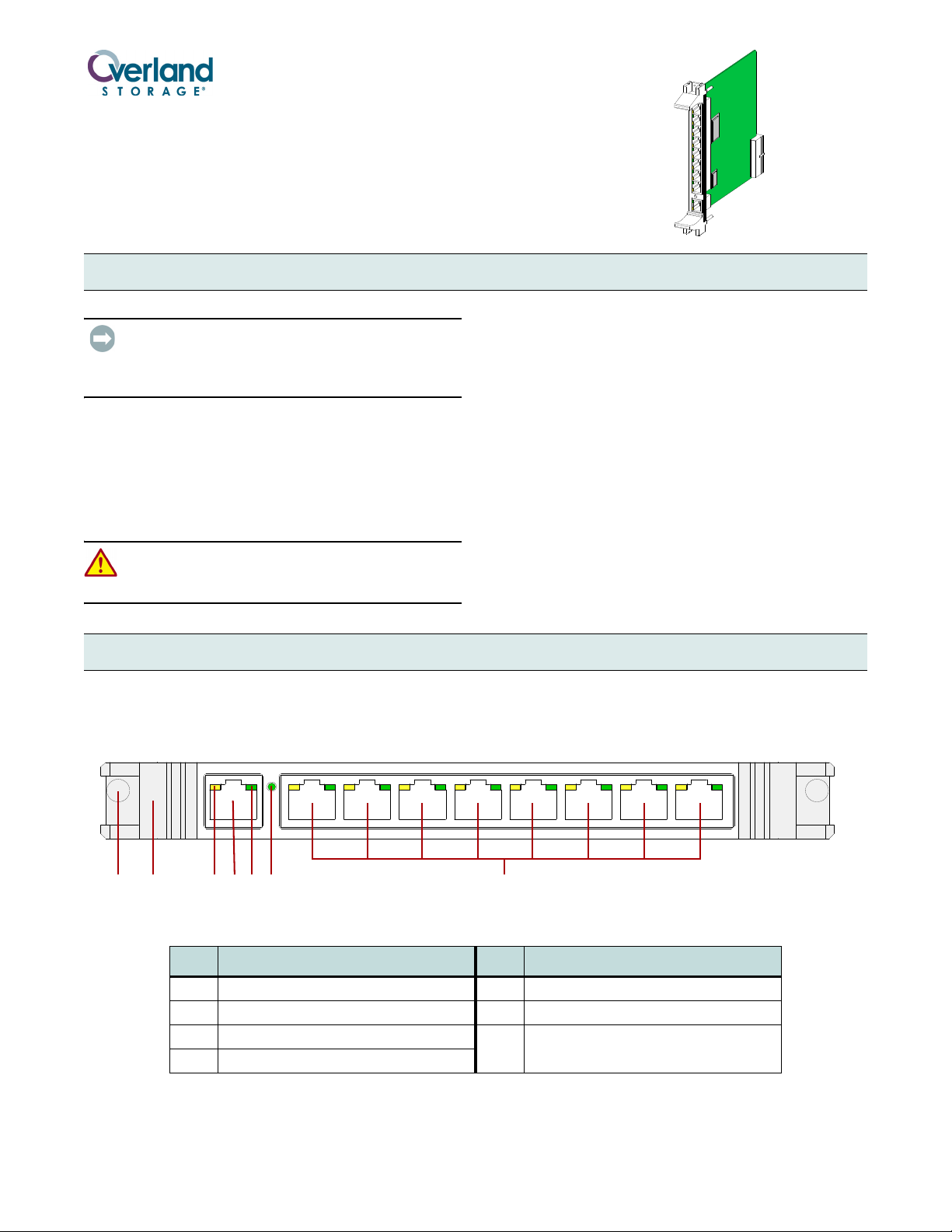
Router Card Layout
The V.I.A. Router card (Figure 1) is a special purpose
device designed to provide a communication interface for a
NEO SERIES Library when in a Master/Slave
Figure 1. Router Card
Item Description Item Description
1 Screw 5 Network LED (Green) – All Ports
2 Card Handle 6 100 BaseT Speed Indicator (Green)
3 Activity LED (Amber) – All Ports 7 Eight Ethernet Ports, Labeled 1 – 8,
4 WAN Port
configuration (such as partitioned or multi-module). To the
external network, it functions as an endpoint device, not a
network router or switch.
with Activity and Network LEDs
Part Number 10400136-102 05/2008 ©2007-2008 Overland Storage, Inc. Page 1 of 4
Page 2
Router Card Installation
N
E
O
-
8
0
4
9
c
V
I
A
-
0
0
7
6
NEO 8000
V
I
A
-
0
0
7
5
NEO 2000
NEO 4000
Follow these steps to install the NEO Series Router card.
CAUTION: For the NEO 8000, the Router card is
designed to function only in the Primary (lower) card
cage and does not work in the Secondary (upper) card
cage. For the NEO 4000, it must go in the upper card
cage. In all models, the far right slot is reserved for the
Library Controller card.
1. At the front panel, power down the library.
2. Remove and retain the power cords.
For the NEO 8000, also set the library circuit
breakers to OFF (“O”).
3. Remove one of the V.I.A. option bay filler plates by
unscrewing the upper and lower retaining screws.
Keep the filler plate for future use.
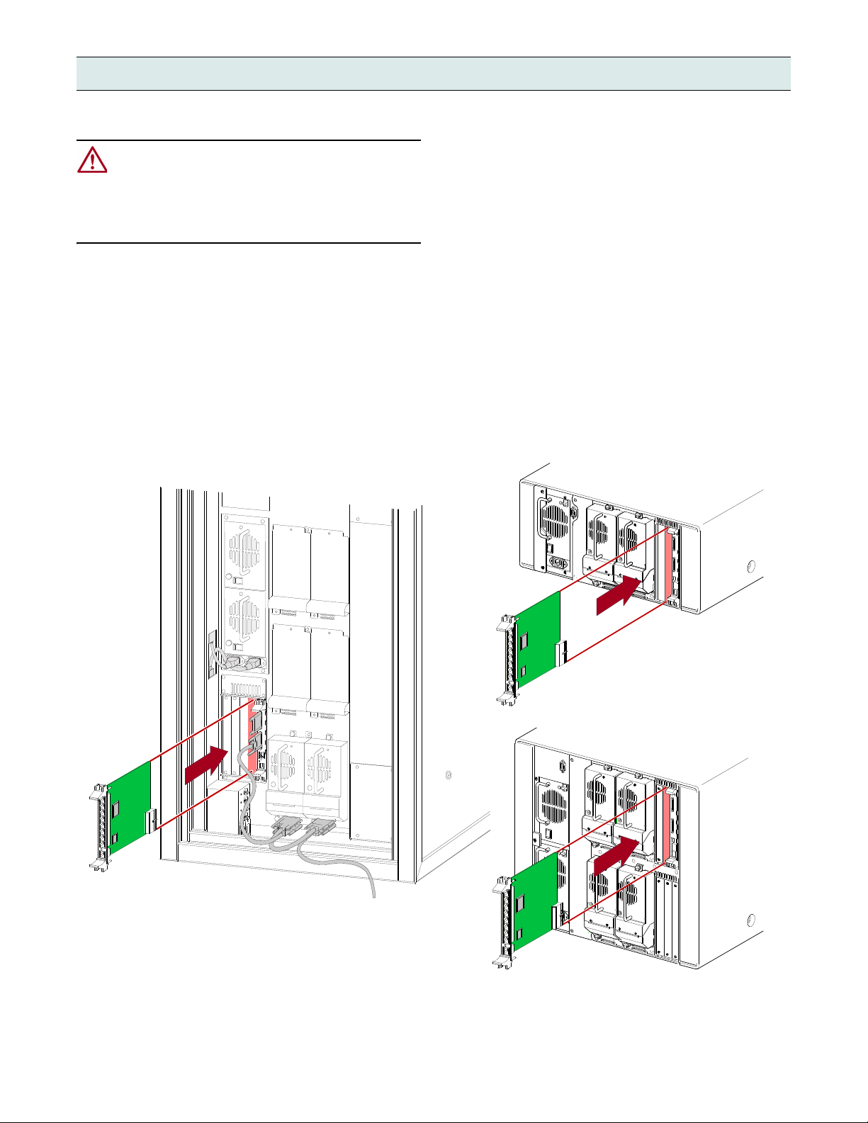
4. Carefully insert the Router card into the upper and
lower guide rails of the option bay and the rear plug at
the bottom. Slide the card into the bay (Figure 2).
Resistance will be felt when the Router card begins to
mate with the library backplane.
5. Using the card handles, apply just enough force to seat
the card snugly into the library backplane to ensure
proper connectivity.
6. Tighten the hold-down screws on the card.
7. Connect the cables for your desired configuration.
See Figure 3 on page 3. Also refer to the user guide that
came with your library.
NOTE: Use the supplied cables to connect to the Library
Controller card and either the LPO card or Slave module.
8. Reattach the power cords and, on the NEO 8000, set
the library circuit breakers to ON (“|”).
The library should power up normally.
Part Number 10400136-102 05/2008 ©2007-2008 Overland Storage, Inc. Page 2 of 4
Figure 2. Inserting the Router Card into a NEO SERIES Library
Page 3

Router Card Configuration
N
E
O
-
8
0
5
1
Ter mina tor
Partition 1 (P1)
PØP1
Partition Ø (PØ)
Ter mina tor
Host 1
Host 2
Primary (Lower)
Card Cage
PC Running
Neo8000Center
Library Controller
Internal Router
Partition Controller
Drive 1Drive 2
Drive 3Drive 4
Numerous cabling configurations are available dependent
on number of drives and hosts. Shown below is an example
of the recommended cable configurations for two partitions
on a NEO 8000 with four drives and two hosts.
NOTE: The same principles apply to NEO 2000 and NEO
4000. The NEO 2000 and NEO 4000 models use NeoCenter
software.
When there is two different operating systems, such as a
mix of Solaris and Win2K servers, a NEO 8000 can be
partitioned into two virtual libraries (Figure 3) to accept
backup commands from the two different systems. The
following example has two drives allocated to each
partition.
Since the Library Controller card acts as the initial
partition (PØ), only one LPO card is needed to create the
second partition (P1). A router card is needed to provide
communication between the LPO card and the robotics via
the Library Controller card.
1. Connect two drives to Partition Ø (PØ).
2. Connect two drives to Partition 1 (P1).
Part Number 10400136-102 05/2008 ©2007-2008 Overland Storage, Inc. Page 3 of 4
Figure 3. Network Layout for a NEO 8000 with 4 Drives Configured as 2 Partitions and 2 Hosts
a. Connect Drive 2 to one of the SCSI ports on the
Library Controller card.
b. Connect Drive 1 to the other SCSI port on Drive 2.
c. Connect a terminator to the other SCSI port on
Drive 1.
a. Connect Drive 4 to one of the SCSI ports on the
Partition Controller card.
b. Connect Drive 3 to the other SCSI port on Drive 4.
c. Connect a terminator to the other SCSI port on
Drive 3.
3. Connect the NEO 8000 to the Host networks.
a. Connect the remaining SCSI port on the Library
Controller (PØ) to Host 1.
b. Connect the remaining SCSI port on the Partition
Controller (P1) to Host 2.
Page 4

4. Connect the partitions to the internal Router card.
a. Connect the RJ-45 connection on the Library
Controller (PØ) to the Router.
b. Connect the RJ-45 connection on the Partition
Controller (P1) to the Router.
5. Connect the NEO 8000 to the Host computer with
Neo8000Center software.
a. Connect the RJ-11 end of the RJ-11 to DB-9 cable to
the RS-232 socket on the Library Controller card.
b. Connect the DB-9 adaptor to a COM port on the
Host computer with Neo8000Center software.
NOTE:
Be sure to connect directly to the Host computer
with the Neo8000Center software and NOT the network.
6. If desired, connect the WAN port on the Router to the
WAN/LAN.
7. Power up the NEO 8000.
8. Using Neo8000Center, configure the partitions.
Refer to the NEO 8000 User Guide for details.
You can get additional technical support on the Internet at http://support.overlandstorage.com, or call
Additional Help
1-877-654-3429 (toll-free U.S. & Canada), +44 (0) 118-9898050 (Europe), or +1 (858) 571-5555 Option 5 (International).
Part Number 10400136-102 05/2008 ©2007-2008 Overland Storage, Inc. Page 4 of 4
 Loading...