

Page 1
Quick Start Guide
ARCvault 48
TM
This document describes how to unpack and install an
ARCvault 48 library into a standard RETMA 19" rack. The
library has a 4U form factor.
Each unit comes with a Rack Kit and an Accessory Kit
containing these items:
• Read Me First document
• Power cord
• Bar code labels
• Magazine Release Tool
• Documentation CD with a PDF of the user guide
• This ARCvault 48 Quick Start Guide
For SCSI drive models, the Accessory Kit also includes:
• LVD SCSI cable, 2m (6.5 ft.)
• SCSI terminator
Before unpacking the unit, ensure that the area is free
from conditions that cause electrostatic discharge (ESD).
First Things First—Activate Your Warranty!
Before installing your new unit, it is essential that you
activate your ARCvault warranty. Technical and warranty
support are not available until this is done.
All that is required is for you to register your unit at the
Overland Technical Support website.
1. Go to the Overland Technical Support website at:
http://support.overlandstorage.com/
2. Using the MEMBER LOGIN E-mail and Password
fields, log in to the site.
NOTE: If you are not yet a member,
click the SIGN UP NOW button and
follow the instructions to become a
member. It’s free!
3. Under MY PRODUCTS, click Add
or Register a New Product and
follow the on-screen instructions.
Unpacking the ARCvault Unit
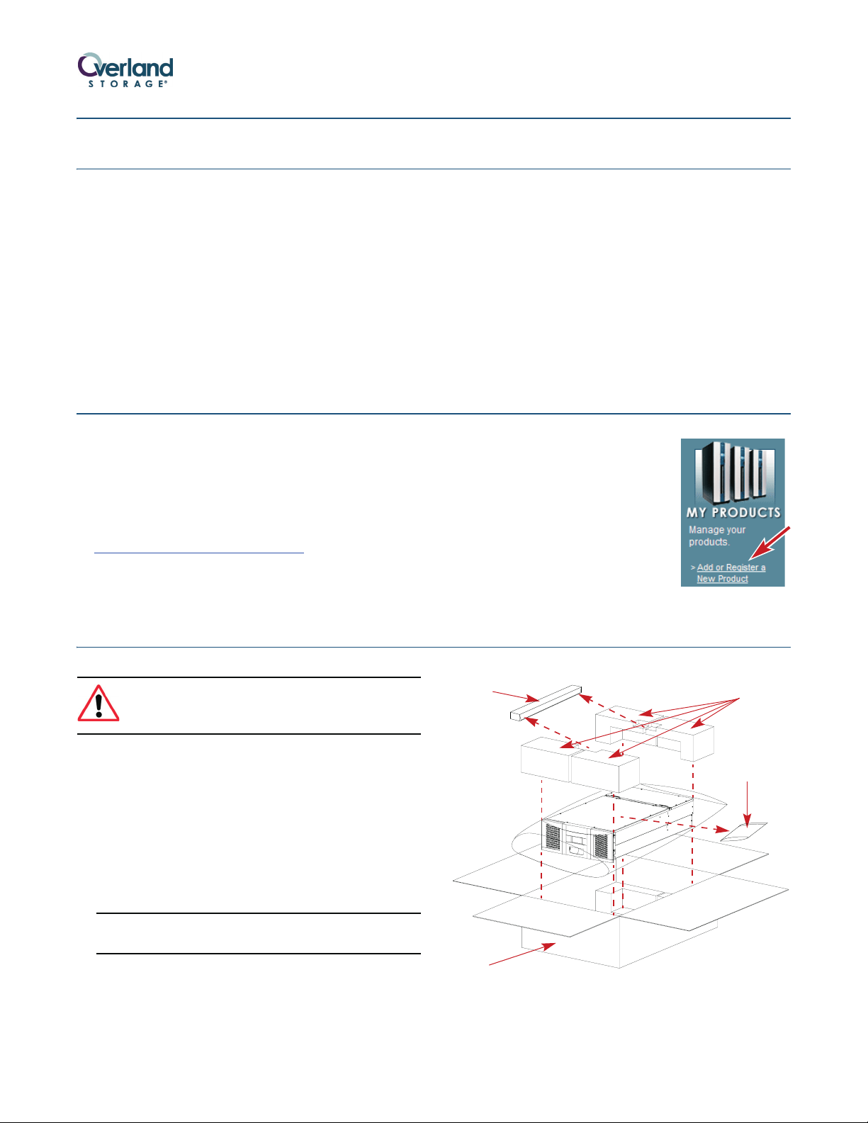
WARNING: Due to the weight of the unit, it is
recommended that at least two people be used to
lift the unit out of the box to prevent injury.
1. Open the top of the box (Figure 1) and remove both the
Rack Kit box and Accessory Kit bag.
2. Remove the top caps.
3. Lift the ARCvault out and set it on a secure surface.
4. Remove the ESD bag from the library.
5. Using the enclosed Important Unpacking Instructions,
remove the screws and well nuts underneath and the
shuttle bracket inside.
CAUTION: The screws and bracket hold the robotics in place
for shipment and MUST be removed before operating.
6. Place all packaging components in the box.
7. Save the box in case you ever need to ship the unit.
Rack Kit
Carton
Figure 1. Unpacking an ARCvault 48
Top Caps
Accessory
Kit
6
2
1
0
C
R
A
Part Number 10400007-101 04/2007 ©2007 Overland Storage, Inc. W Page 1 of 4
Page 2

Installing the Rack Kit
A
R
C
0
0
9
6
Every ARCvault 48 comes with a tray-style Rack Kit that
allows you to easily install and remove the unit without
having to engage side rails. The Rack Kit includes all
mounting hardware.
WARNING: It is recommended that a mechanical
lifter (or at least two people) be used to raise and
align the unit to prevent injury during installation.
WARNING: Use care when inserting or removing an
ARCvault unit into or out of a rack to prevent the
accidental tipping of the unit causing damage or
personal injury.
1. Locate and mark the holes for the rails and retaining
screws:
a. Starting with the right front flange, at the bottom
of the rack (or from the top of a previously mounted
component), locate the first set (Figure 2) of three
holes with equal gaps of 5/8 inch (1.6cm).
Retaining Screw
Hole Mark
Right
Front Flange
4U
b. Move the rear bracket so that the PEM studs are
in different slots (Figure 3) based on the rack size.
• For a 36" rack, use the two front slots.
• For a 30" rack, use the two center slots.
• For a 24" rack, use the two rear slots.
Adjust Rear Bracket to Fit
Front
PEM Studs and Lock Nuts
Figure 3. Outside Rail Adjustment for 30” Rack
c. Loosely replace the retained washers and screws.
d. Repeat Steps a–c for the left rail.
4. Using the eight SEMS screws and four bar nuts
provided, attach the rails (Figure 4) inside the flanges:
NOTE: To ensure proper alignment, the bar nut corner
notches must face outside, away from the rail.
a. Attach the right rail inside the marked locations
(Figure 4) of the right front and right rear flanges.
b. Tighten the adjustment nuts.
c. Repeat Steps a–b for the left rail.
Rear Flanges
3
6
0
0
C
R
A
Retaining Screw
Hole Mark
Top Rail
Hole Mark
Bottom Rail
Hole Mark
9
5
0
0
C
R
A
First
Hole
Set
5/8" (1.6cm)
1/2" (1.3cm)
5/8" (1.6cm)
5/8" (1.6cm)
Figure 2. Holes Used for Attaching Rack Kit Rails
b. Mark the top and bottom holes of the set for the
rail screws.
c. Mark the second and eighth holes above the set
for the retaining screws.
d. Repeat Steps a–c for the left side.
2. Repeat Step 1 for the rear holes.
CAUTION: Be sure rear holes are horizontally in line with the
front holes to assure the unit remains level.
3. Adjust the rail rear brackets to fit the rail inside the
rack flanges:
a. Remove and retain the two adjustment nuts and
washers on the right rail.
Front Flanges
Clip Nuts
Bar Nut
Rail Adjustment Nuts
Figure 4. Attaching the Rack Kit Rails
5. Attach four clip-nuts to the holes marked on the
front rack flanges for the retaining thumbscrews.
6. Lift the ARCvault unit and gently slide it into the
rack until the front panel touches the rack.
7. Tighten the four retaining thumbscrews behind the
doors to secure the unit to the rack.
-
Part Number 10400007-101 04/2007 ©2007 Overland Storage, Inc. W Page 2 of 4
Page 3

ARCvault Overview
Tape cartridges are loaded using the tape magazines
provided. The ARCvault 48 has four magazines, two on
each side. As a safety feature, the magazine doors must be
shut before the internal robotics can function.
Open Door
Tape Cartridge Magazines
Retaining Thumbscrews Operator Control Panel
Figure 5. ARCvault Front Panel
All cabling and power connections, along with the unit’s
power switch, are located on the rear panel (Figure 6). On
a SCSI configuration, the top two SCSI ports connect to
Drive 1 and the bottom two ports connect to Drive 2.
There are two ways to interface with an ARCvault unit—
the Operator Control Panel (OCP) touch screen on the
front panel (Figure 5) or Remote Management Utility
(RMU) accessed via a web browser using the default IP
address of 10.0.0.1.
Door Handle
7
3
0
0
C
R
A
Ventilation Slots
Access to the tape drive bay is available through the tape
drive cover assemblies. Connections are available for
Ethernet and serial cabling. All unit cooling exhaust is
handled through the rear panel.
SCSI Ports
Lower Drive Bay Cover
Thumbscrews
Figure 6. ARCvault Rear Panel (SCSI Configuration)
Attaching Cables
You are ready to connect the unit to your host system. For
additional information, see the ARCvault 48 User Guide.
SCSI Drives - Single Host
The default SCSI configuration is two half-height drives.
System Exhaust FanTap e Driv e Cover
Power Switch
AC Receptacle
9
0
0
0
C
R
A
Ethernet Port Serial Port
1. Connect the LVD SCSI cable to the top SCSI port and
the other end to your system.
2. Attach the SCSI jumper cable between the second
and third ports (Drives 1 and 2).
3. Attach the SCSI terminator to the fourth SCSI port.
Part Number 10400007-101 04/2007 ©2007 Overland Storage, Inc. W Page 3 of 4
Page 4

4. Plug a network connection into the Ethernet port.
5. Plug the power cord into the AC receptacle and the
other end into a power source.
FC Drive - Single Host
The default FC configuration is one full-height drive.
1. Connect your Fibre Channel cabling to either of the
FC ports and the other end to your system (Figure 7).
2. Plug the network connection into the Ethernet port.
3. Plug the power cord into the AC receptacle and the
other end into a power source.
Getting Started
FC Port A FC Port B
Figure 7. FC Drive Cover Assembly
6
3
1
0
C
R
A
Use the following general information to operate the OCP:
• Rectangles are usually buttons. Press to activate them.
• Arrow buttons allow you to scroll through the options.
• Press Back/Cancel to return to a previous screen.
Initial Setup
To get your ARCvault 48 ready for everyday use, follow
these first time use procedures.
1. Tap the OCP touch screen to power on the unit.
Wait about 5 minutes for Power-On Self-Test (POST) to
complete and the Default (Figure 8) screen to display.
Figure 8. Default OCP Screens
2. For a SCSI unit, change the SCSI ID numbers if they
need to be different than the default settings of 1 and 2:
a. Press Setup > Edit Opts > SCSI/FC > OK (at going
offline message).
b. Press the Drv 1 Bus ID data field on the right.
c. Press the New data field.
d. Using the pop-up keyboard, enter the new SCSI
ID number and press OK.
e. Press Save and then press OK to confirm.
f. Repeat Steps Steps a–e for the other drive.
g. Press Back three times.
3. Load the tape media into the magazines:
CAUTION: Keep a loaded magazine level. Tilting the
magazine can result in the tapes falling out and possibly
being damaged. Also, don’t hold a magazine by just the
handle; use both hands to support it.
a. At the Default screen, press Media > Mag Access >
OK (at going offline message) > Unlock All.
b. Open doors, remove magazines, load tape
cartridges, reinsert magazines into the same bays,
and close doors.
Each magazine relocks automatically.
NOTE: If you did not remove all ARCvault 48 magazines,
you must press Relock All before continuing.
c. Press Back once.
Wait while the unit inventories the magazines.
d. Press Back again to return to Default screen.
Additional Information
Your system is now ready for use. For more options,
including the creation of partitions, refer to the ARCvault
48 User Guide found on the ARCvault Documentation CD
in the Accessory Kit.
You can get additional technical support on the Internet at http://support.overlandstorage.com,
Additional Help
or call 1-877-654-3429 (toll-free U.S. & Canada), +44 (0) 118-9898050 (Europe), or
All information contained in or disclosed by this document is considered proprietary by Overland Storage. By accepting this material, the recipient agrees that this material and the information contained therein are
held in confidence and in trust and will not be used, reproduced in whole or in part, nor its contents revealed to others, except to meet the purpose for which it was delivered. It is understood that no right is conveyed
to reproduce or have reproduc ed any item herein disclosed without express permission from Overland Storage. Overland St orage provides this document as is, without warranty of any kind, either expressed or
implied, including, but not limited to, the implied warranties of merchantability and fitness for a particular purpose. Overland Storage may make improvements or changes in the product(s) or program(s) described
in this document at any time. These changes will be incorporated in new editions of this publication.
Overland Storage assumes no responsibility for the accuracy, completeness, sufficiency, or usefulness of this document, nor for any problem that might arise from the use of the information in this document.
Part Number 10400007-101 04/2007 ©2007 Overland Storage, Inc. W Page 4 of 4
+1 (858) 571-5555 Option 5 (International).
 Loading...