

Page 1
Quick Start Guide
(E-Mail) (Password)
A
Rack Kit &
End Cap
ESD
Bag
End Cap
CAUTION: Shuttle Bracket & Bottom
Screws MUST be Removed!
Accessory Kit
ARCvault®12 & 24
This document describes how to unpack and install either
an ARCvault 12 loader or ARCvault 24 library into a
standard RETMA 19" rack using only 2U of space. The
units come with either SCSI, Fibre Channel (FC), or SAS
drives installed.
Each unit comes with the tray-style Rack Kit and an
Accessory Kit containing these items:
• Read Me First document
• Power cord
• Bar code labels
• Magazine Release Tool
• Serial cable (for Service use only)
• Documentation CD with a PDF of the user guide
• This quick start guide
For SCSI drive models, the Accessory Kit also includes:
• LVD SCSI cable, 2m (6.5 ft.)
• SCSI terminator
For SAS drive models, the kit also includes:
• SAS cable, 3m (9.75 ft.)
Before unpacking the unit, ensure that the area is free
from conditions that cause electrostatic discharge (ESD).
First Things First—Activate Your Warranty!
Before installing your new unit, it is essential that you
activate your ARCvault warranty. Technical and warranty
support are not available until this is done:
1. Go to the Overland Technical Support website at:
http://support.overlandstorage.com/
2. Using the MEMBER LOGIN, log in to the site.
NOTE: If you are not yet a member, click the New member?
link (Figure 1) and follow the instructions. It’s free!
3. From the menu on the left, select My Products > Add
or Register a Product, and follow the on-screen
instructions.
Figure 1. Login and Sign-up Links
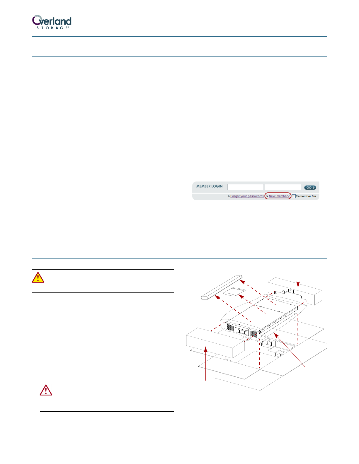
Unpacking the ARCvault Unit
WARNING: Due to the weight of the unit, it is
recommended that at least two people be used to lift
the unit out of the box to prevent injury.
Both the ARCvault 12 and ARCvault 24 come packaged in
the same type of container.
1. Open the top of the box (Figure 2) and lift off the top
end caps.
2. Remove the Rack Kit and Accessory Kit.
3. Lift the ARCvault out and set it on a secure surface.
4. Remove the ESD bag.
5. Using the enclosed Important Unpacking Instructions,
remove both the screws and well-nuts underneath
and the shuttle bracket inside the front left door.
CAUTION: The screws and bracket hold the robotics
in place for shipment and MUST be removed before
operating. Refer to the Important Unpacking
Instructions for details.
6. Place all the packaging components inside the box and
save the box in case you ever need to ship the unit.
Part Number 10400006-106 06/2008 ©2006-2008 Overland Storage, Inc. Page 1 of 4
Figure 2. Unpacking an ARCvault
Page 2
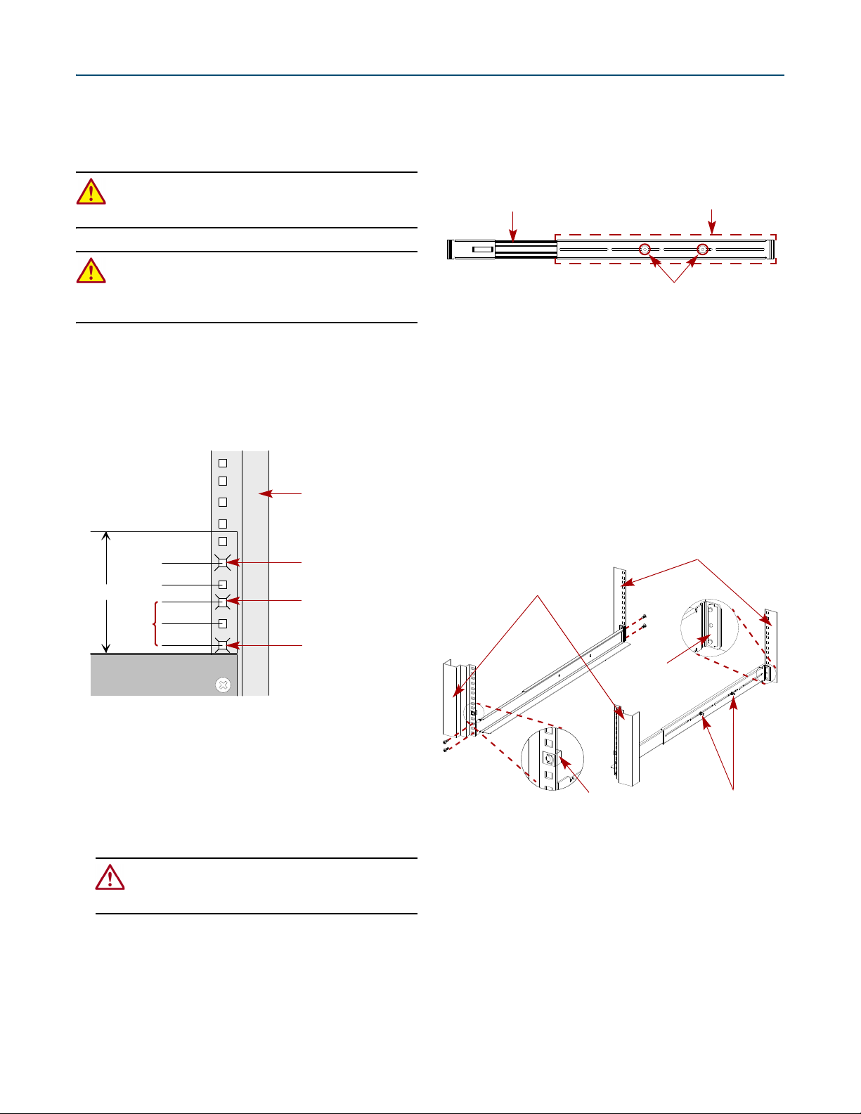
Installing the Rack Kit
1/2" (1.3cm)
5/8" (1.6cm)
2U
A
R
C
-
0
0
3
0
5/8" (1.6cm)
5/8" (1.6cm)
First
Hole
Set
Retaining Screw
Top Rai l
Hole Mark
Bottom Rail
Hole Mark
Hole Mark
Right Front Flange
A
R
C
-
0
0
6
3
Adjust Rear Bracket to Fit
PEM Studs and Lock Nuts
Front Bracket & Rail Assembly
A
R
C
-
0
0
9
4
Front Flanges
Rear Flanges
Adjustment Nuts
Bar Nut
Clip Nut
Every ARCvault comes with a tray-style rack kit that
allows you to easily install and remove the unit without
having to engage side rails. The rack kit includes all
mounting hardware.
WARNING: It is recommended that a mechanical lifter
(or at least two people) be used to raise and align the
unit to prevent injury during installation.
WARNING: Use care when inserting or removing an
ARCvault unit into or out of a rack to prevent the
accidental tipping of the unit causing damage or
personal injury.
1. Locate and mark the holes for the rails and retaining
screws.
a. Starting with the right front flange at the bottom
of the rack (or from the top of a previously mounted
component), locate the first set (Figure 3) of three
holes with equal gaps of 5/8 inch (1.6cm).
b. Move the rear bracket so that the two PEM studs
are in different slots (Figure 4).
• For a 36" rack, use the two front slots.
• For a 30" rack, use the two center slots.
• For a 24" rack, use the two rear slots.
Figure 4. Outside Rail Adjustment
c. Loosely replace the retained washers and screws.
d. Repeat Steps a–c for the left rail.
4. Using the eight screws and four bar nuts provided,
attach the rails (Figure 5) inside the flanges:
NOTE: To ensure proper alignment, the bar nut corner
notches must face outside, away from the rail (Figure 5).
a. Attach the right rail inside the marked locations
(Figure 5) of the right front and right rear flanges.
b. Tighten the adjustment nuts.
c. Repeat Steps a–b for the left rail.
Figure 3. Holes Used for Attaching Rails
b. Mark the top and bottom holes of the set for the
rail screws.
c. Mark the second hole above the set for the
retaining screw.
d. Repeat Steps a–c for the left side.
2. Repeat Step 1 for the rear holes.
CAUTION: Be sure that the rear holes are
horizontally in line with the front holes. This assures
that the unit is level so that it can operate properly.
3. Adjust the rail rear brackets to fit the rail inside the
rack flanges.
a. Remove and retain the two adjustment nuts and
washers on the right rail.
Part Number 10400006-106 06/2008 ©2006-2008 Overland Storage, Inc. Page 2 of 4
Figure 5. Attaching Outside Rails
5. Attach two clip-nuts to the holes marked on the front
rack flanges for the retaining thumbscrews.
6. Lift the ARCvault unit and gently slide it into the
rack until the front panel touches the rack.
7. Tighten the two retaining thumbscrews behind the
doors to secure the unit to the rack.
Page 3

ARCvault Overview
A
R
C
-
0
0
2
3
Retaining ThumbscrewOperator Control Panel
Tape Cartridge Magazine Door Handle
Ventilation Slots Open Door
A
R
C
-
0
1
7
6
SCSI Ports
AC Receptacle
Ethernet
USB (Non-Implemented)
Serial
Power Switch
Thumbscrews
System Exhaust FanTap e Dr ive Cove r
Tape cartridges are loaded using the tape magazines
provided. The ARCvault 12 has one magazine on the right
side while the ARCvault 24 has two magazines, one on
each side. As a safety feature, the magazine doors must be
shut before the internal robotics can function.
There are two ways to interface with an ARCvault unit—
using the Operator Control Panel (OCP) touch screen on
the front panel or by accessing the unit’s Remote
Management Utility (RMU) via a web browser.
Figure 6. ARCvault Front Panel
The OCP on the front panel (Figure 6) provides an easy
way to directly communicate with the unit and make
changes that are related to the use and movement of
physical media.
The RMU provides remote access to additional features,
functions, and options. It provides information in greater
detail than what is found on the OCP.
IMPORTANT: The default RMU IP address for logging on is
10.0.0.1.
All cabling and power connections, along with the unit’s
power switch, are located on the rear panel (Figure 7).
Access to the tape drive bay is available through the tape
drive cover assembly by loosening just two thumbscrews
Figure 7. ARCvault Rear Panel (with SCSI Drive Cover Assembly)
Attaching Cables
You are ready to connect the unit to your host system. For
additional information, see the ARCvault 12 & 24 User
Guide.
IMPORTANT: To function at its maximum rate, each SCSI
tape drive must be on a separate SCSI bus.
1. Connect the appropriate cables for the drive type used:
allowing easy upgrading or replacement of a drive.
Connections are available for Ethernet and serial cabling.
All unit cooling exhaust is handled through the rear panel.
•SCSI Drive – Connect the LVD SCSI cable to the
top SCSI port and your system, and attach SCSI
terminator to the bottom SCSI port (Figure 7).
•FC Drive – Connect your Fibre Channel cabling
to either of the FC ports and the other end to your
system (Figure 8 on page 4).
•SAS Drive – Connect the SAS cable to the SAS port
on the drive cover and the other end to your system
(Figure 8 on page 4).
Part Number 10400006-106 06/2008 ©2006-2008 Overland Storage, Inc. Page 3 of 4
Page 4

Figure 8. FC and SAS Drive Cover Assemblies
A
R
C
-
0
1
8
6
SAS
A
R
C
-
0
1
3
6
Fibre Channel (ARCvault 24 only)
FC Port A FC Port B
2. Plug a network connection into the Ethernet port. 3. Plug the power cord into the AC receptacle and the
other end into a power source.
Getting Started
Use the following information to operate the OCP:
• Rectangles with text usually represent buttons on the
OCP screen. Press inside a rectangle to activate it.
• Arrow buttons allow you to scroll through the options.
The end or beginning of the list has only one arrow.
• Pressing the Back or Cancel button on secondary
screens returns you to the previous screen.
Initial Setup
To get your ARCvault unit ready for everyday use, follow
these first time use procedures.
1. Tap the OCP touch screen to power on the unit.
Wait 2–3 minutes for Power-On Self-Test (POST) to
complete and the Default (Figure 9) screen to be
displayed.
Figure 9. Default OCP Screens
2. If necessary, change the unit’s SCSI ID (only if it needs
to be different than the default setting of 1).
a. Press Setup > Edit Opts > SCSI/FC (pressing OK
at the going offline message).
b. Press the Drv 1 Bus ID data field on the right.
c. Press the New data field.
d. Using the pop-up keyboard, enter the new ID
number and press OK.
e. Press Save and then press OK to confirm.
f. When the screen resets, press Back three times.
3. Load the tape media using the magazines.
CAUTION: Keep a loaded magazine level. Tilting the
magazine can result in the tapes falling out. Also,
don’t hold a magazine by just the handle; use both
hands to support it.
a. Press Media > Mag Access > Unlock All (pressing
OK at the going offline message).
b. Remove the right magazine, insert any tape
cartridges, and reinsert the magazine.
The magazine relocks automatically.
c. For an ARCvault 24, repeat Step b for the left
magazine.
NOTE:
If you did not remove both ARCvault 24 magazines,
you must press Relock All before continuing.
d. Press Back.
Wait while the unit inventories the magazines.
e. Press Back again to return to the Default screen.
Additional Information
Your system is now ready for use. Refer to the user guide
for your ARCvault model found on the ARCvault
Documentation CD for more options including:
• Changing the default Static IP address of 10.0.0.1 to a
different address or DHCP.
• Setting or changing passwords.
• Moving media within the unit.
• Configuring other features and options.
Additional Help
You can get additional technical support on the Internet at http://support.overlandstorage.com, or call
1-877-654-3429 (toll-free U.S. & Canada), +44 (0) 118-9898050 (Europe), or +1 (858) 571-5555 Option 5 (International).
Part Number 10400006-106 06/2008 ©2006-2008 Overland Storage, Inc. Page 4 of 4
 Loading...