

Page 1

ARCvault
Series
Autoloader/Library
™
Service Manual
Part Number 10400025-101
October 2006
Page 2

Proprietary Notice
All information contained in or disclosed by this document is considered proprietary by Overland Storage. By
accepting this material, the recipient agrees that this material and the information contained therein are held
in confidence and in trust and will not be used, reproduced in whole or in part, nor its contents revealed to
others, except to meet the purpose for which it was delivered. It is understood that no right is conveyed to
reproduce or have reproduced any item herein disclosed without express permission from Overland Storage.
Overland Storage provides this manual as is, without warranty of any kind, either expressed or implied,
including, but not limited to, the implied warranties of merchantability and fitness for a particular purpose.
Overland Storage may make improvements or changes in the products or programs described in this manual at
any time. These changes will be incorporated in new editions of this publication.
Overland Storage assumes no responsibility for the accuracy, completeness, sufficiency, or usefulness of this
manual, nor for any problem that might arise from the use of the information in this manual.
Overland products are covered by one or more of the following patents registered with the USPTO: 5,870,245; 6,328,766; 6,353,581; 6,496,325.
Overland®, Overland Storage®, XchangeNOW®, VR2®, WebTLC®, PowerLoader®, LoaderXpress®, NEO SERIES®, and REO SERIES® are registered trademarks of
Overland Storage, Inc. Simply iSCSI™, Simply Protected™, Simply Protected Storage™, SnapWrite™, ULTAMUS™, ULTAMUS SERIES™, ULTAMUS PRO™,
ULTAMUS RAID™, REO™, NEO™, ARCvault™, ARCvault SERIES™, Protection OS™, Multi-SitePAC™, NDMP PAC™, CompliancePAC™, VTLPac™, and
D2D2T™ are trademarks of Overland Storage, Inc.
© 2006 Overland Storage, Inc. All rights reserved.
Worldwide Headquarters Overland Storage, Inc.
4820 Overland Avenue
San Diego, CA 92123
Toll Free: (800) 729-8725
Tel: (858) 571-5555
Fax: (858) 571-0982
Sales Tel: (858) 571-5555
Fax: (858) 571-3664
E-mail: sales@overlandstorage.com
http://www.overlandstorage.com
Technical Support Tel: (858) 571-5555
Fax: (858) 495-4202
Toll Free: (877) 654-3429
International: 001 (858) 571-5555 x5
E-mail: techsupport@overlandstorage.com
http://support.overlandstorage.com
Overland Storage, EMEA Overland House, Ashville Way
Wokingham, Berkshire
RG41 2PL, England
Tel: +44 (0) 118-9898000
Fax: +44 (0) 118-9891897
http://www.overlandstorage.com
ii Part Number 10400025-101 10/2006
Page 3
About this Manual
This service manual provides detailed information necessary for upgrading or repairing an
Overland Storage ARCvault Series™ autoloader or library. It is designed to be used only by
Overland-authorized service technicians.
Product Documentation
ARCvault product documentation and additional literature are available online at
http://www.overlandstorage.com.
Conventions
This service manual exercises several typographical conventions to help explain how to use the
ARCvault.
Convention Description & Usage
Boldface Words in boldface indicate items to select such as menu items or command
Ctrl-Alt-r This type of format details the keys you press simultaneously. In this example, hold
NOTE A Note indicates neutral or positive information that emphasizes or supplements
IMPORTANT An Important note is a type of note that provides information essential to the
CAUTION A Caution contains information that the user needs to know to avoid damaging or
WARNING A Warning contains information essential to people’s safety. It advises
buttons.
down the Ctrl and Alt keys and press the r key.
important points of the main text. A note supplies information that may apply only
in special cases—for example, memory limitations or details that apply to specific
versions of a program.
completion of a task or that can impact the product and its function.
permanently deleting data or causing physical damage to the hardware or system.
users that failure to take or avoid a specific action could result in
physical harm to the user or hardware.
Firmware Updates
The latest release of the ARCvault firmware can be obtained from the Overland Storage FTP
site.
1. Point your browser to ftp://ftp.overlandstorage.com/Firmware/ARCvault/.
2. Open the ARCvault folder.
3. Download the latest firmware file labeled ARCvault_nnnn.bin (where “nnnn” represents the
latest version number).
For additional assistance, search at http://support.overlandstorage.com/.
10400025-101 10/2006 iii
Page 4

Electrostatic Discharge Information
A discharge of static electricity can damage static-sensitive devices. Proper packaging and
grounding techniques are necessary precautions to prevent damage. To prevent electrostatic
discharge (ESD) damage, observe the following precautions:
• Transport products in static-safe containers such as conductive tubes, bags, or boxes.
• Keep electrostatic-sensitive parts in their containers until they arrive at static-free stations.
• Cover the loader or library with approved static-dissipating material.
• Use an ESD wrist strap connected to the work surface and grounded tools and equipment.
• Keep the work area free of non-conductive materials such as foam packing materials.
• Make sure you are always properly grounded when touching a static-sensitive component or
assembly.
• Avoid touching pins, leads, or circuitry.
Overland Technical Support
For assistance configuring and using your ARCvault, search for help at:
http://support.overlandstorage.com/
Our Overland Storage Technical Support staff is also available to assist you by phone at:
1 (877) 654-3429 (Toll-free and active only in US and Canada)
001 (858) 571-5555 x5 (Worldwide)
They are available on normal business days, 6 AM through 5 PM (PT), excluding Overland
holidays. At all other times we will respond to technical support calls within 4 hours.
Technical support for our European customers is available as well from our United Kingdom
office at:
+44 (0) 118-9898050
9:00 AM to 5:00 PM (GMT)
Monday through Friday
You can e-mail our technical support staff at techsupport@overlandstorage.com.
iv 10400025-101 10/2006
Page 5

Table of Contents
Section 1 - General Information
1.1 Safety ....................................................................................................................................................... 1-1
1.2 General Description ............................................................................................................................... 1-2
1.3 Version Control ....................................................................................................................................... 1-2
1.4 ARCvault Models Covered ................................................................................................................... 1-2
1.5 Specifications ......................................................................................................................................... 1-3
1.5.1 Physical Specifications ................................................................................................................. 1-3
1.5.2 Technical Information .................................................................................................................. 1-4
1.5.3 Reliability and Safety .................................................................................................................... 1-4
1.5.4 Temperature, Humidity and Altitude .......................................................................................... 1-5
1.5.5 Shock ............................................................................................................................................. 1-5
1.5.6 Vibration ........................................................................................................................................ 1-6
1.5.7 Electromagnetic Emissions .......................................................................................................... 1-7
Section 2 - System Overview
2.1 Installation ............................................................................................................................................... 2-1
2.1.1 Shipping Tie-Down Wire ............................................................................................................... 2-1
2.1.1.1 Tie-Down Removal .............................................................................................................. 2-1
2.1.1.2 Tie-Down Reinstallation for Shipment ................................................................................ 2-2
2.1.2 Rack Considerations .................................................................................................................... 2-3
2.1.2.1 Installing an ARCvault Library ............................................................................................ 2-3
2.1.2.2 Removing ARCvault Library for Service ............................................................................ 2-6
2.2 Attaching Cables ................................................................................................................................... 2-6
2.3 Power Management ............................................................................................................................. 2-7
2.3.1 Power-On Process ........................................................................................................................ 2-7
2.3.2 Power-Off Process ........................................................................................................................ 2-8
2.4 Interfaces ................................................................................................................................................ 2-8
2.4.1 Operator Control Panel ............................................................................................................... 2-8
2.4.1.1 ARCvault OCP Software Maps .......................................................................................... 2-9
2.4.2 Remote Management Utility ..................................................................................................... 2-10
2.4.2.1 ARCvault RMU Software Map .......................................................................................... 2-11
2.5 Password Protection ............................................................................................................................ 2-12
2.6 Tape Magazines ................................................................................................................................... 2-13
2.6.1 Slot Management ...................................................................................................................... 2-13
2.6.2 I/E Element .................................................................................................................................. 2-15
2.6.2.1 Single-Slot I/E Element ....................................................................................................... 2-15
2.6.2.2 Full-Magazine I/E Element ................................................................................................ 2-16
Section 3 - Troubleshooting and FSCs
3.1 Possible Problems ................................................................................................................................... 3-1
3.1.1 Sample Screens ............................................................................................................................ 3-1
3.2 Error Recovery ........................................................................................................................................ 3-1
3.2.1 FSC/ERP Cross-Reference Table ................................................................................................. 3-2
3.2.2 Error Recovery Procedures .......................................................................................................... 3-7
3.3 Tape Drive Removal ............................................................................................................................ 3-16
3.4 Touch Screen Overrides ...................................................................................................................... 3-17
3.4.1 Touch Screen Forced Recalibration .........................................................................................3-18
3.4.2 Touch Screen Contrast Reset .................................................................................................... 3-18
Section 4 - Adding or Replacing Components
4.1 Replacing a Tape Drive ........................................................................................................................ 4-1
4.1.1 Remove the Drive Assembly ....................................................................................................... 4-1
4.1.2 Replace Full-Height Drive ............................................................................................................ 4-2
Part Number 10400025-101 10/2006 v
Page 6

Table of Contents
4.2 Replacing Drive Cover Assembly ......................................................................................................... 4-4
4.3 Replacing A Media Magazine ............................................................................................................. 4-4
4.4 Exchanging a Chassis ............................................................................................................................ 4-5
4.5 Adding a Second Drive to an ARCvault 24 ........................................................................................ 4-8
4.1.3 Replace Half-Height Drive ........................................................................................................... 4-2
4.1.4 Reinstall the Drive ......................................................................................................................... 4-3
4.2.1 Remove Old Assembly ................................................................................................................. 4-4
4.2.2 Install New Assembly .................................................................................................................... 4-4
4.4.1 Removing the Old Chassis ........................................................................................................... 4-5
4.4.1.1 Removing Magazines ......................................................................................................... 4-6
4.4.1.2 Removing the Unit from Rack ............................................................................................ 4-6
4.4.1.3 Removing Drive Assembly .................................................................................................. 4-7
4.4.2 Incorporating the New Chassis ................................................................................................... 4-7
4.4.2.1 Install Drive Assembly .......................................................................................................... 4-7
4.4.2.2 Reattach Drive Cover ......................................................................................................... 4-7
4.4.2.3 Reinstall Unit in Rack ........................................................................................................... 4-8
4.4.3 Reconfiguring the Unit ................................................................................................................. 4-8
4.5.1 Preparing the Unit ......................................................................................................................... 4-8
4.5.1.1 Removing the Unit from Rack ............................................................................................ 4-8
4.5.1.2 Removing Drive Assembly .................................................................................................. 4-8
4.5.2 Installing the New Drive ............................................................................................................... 4-9
4.5.3 Reinstalling the Drive Assembly ................................................................................................. 4-10
Section 5 - Firmware Update
5.1 Using a Local FTP Server ........................................................................................................................ 5-1
5.2 Using a Remote FTP Server .................................................................................................................... 5-1
Index
vi Part Number 10400025-101 10/2006
Page 7

List of Figures
Section 1 - General Information
Figure 1-1: ARCvault 24 Library ..................................................................................................1-1
Section 2 - System Overview
Figure 2-1: Location of Robotics Tie-Down Wire Underneath Library .................................... 2-1
Figure 2-2: Tie-Down Removal.................................................................................................... 2-2
Figure 2-3: Tie-Down Hole Locations (Top View)...................................................................... 2-3
Figure 2-4: Tie-Down in Place ..................................................................................................... 2-3
Figure 2-5: Holes Used for Attaching Rails................................................................................. 2-4
Figure 2-6: Outside Rail Adjustment for 30" Rack ..................................................................... 2-4
Figure 2-7: Attaching Outside Rails............................................................................................ 2-5
Figure 2-8: Tighten Retaining Screws to Rack........................................................................... 2-5
Figure 2-9: ARCvault Rear Connections and Power Switch ................................................... 2-6
Figure 2-10: ARCvault Basic Cabling......................................................................................... 2-7
Figure 2-11: Power-On Points...................................................................................................... 2-7
Figure 2-12: POST Startup Logo Screen ..................................................................................... 2-8
Figure 2-13: OCP Default Screen ............................................................................................... 2-8
Figure 2-14: ARCvault 12 OCP Software Map .......................................................................... 2-9
Figure 2-15: ARCvault 24 OCP Software Map ........................................................................ 2-10
Figure 2-16: ARCvault 12 RMU Software Map ........................................................................ 2-11
Figure 2-17: ARCvault 24 RMU Software Map ........................................................................ 2-12
Figure 2-18: ARCvault 12 Normal Slot Numbering ................................................................. 2-13
Figure 2-19: ARCvault 24 Normal Slot Numbering ................................................................. 2-14
Figure 2-20: Slot Numbering with Single-Slot I/E Element ...................................................... 2-14
Figure 2-21: Slot Numbering with Full-Magazine I/E Element ................................................ 2-14
Figure 2-22: I/E Element Magazine Location.......................................................................... 2-15
Figure 2-23: Removing Single-Slot I/E Element........................................................................ 2-16
Figure 2-24: Single-Slot I/E Element With Tape........................................................................ 2-16
Section 3 - Troubleshooting and FSCs
Figure 3-1: Sample OCP Error Message Screen ....................................................................... 3-1
Figure 3-2: Sample RMU Error Message in Library Health Table.............................................. 3-1
Figure 3-3: General Troubleshooting Procedure ...................................................................... 3-2
Figure 3-4: Error Recovery Procedure 1—Defective Chassis .................................................. 3-8
Figure 3-5: Error Recovery Procedure 2—Defective Chassis or Drive .................................... 3-9
Figure 3-6: Error Recovery Procedure 3—User Configuration Error ...................................... 3-10
Figure 3-7: Error Recovery Procedure 4—User Operation Error ............................................ 3-10
Figure 3-8: Error Recovery Procedure 5—System or Application Error................................. 3-11
Figure 3-9: Error Recovery Procedure 6—Defective Media or Chassis................................ 3-12
Figure 3-10: Error Recovery Procedure 7—Defective Media, Chassis, or Drive .................. 3-13
Figure 3-11: Error Recovery Procedure 8—Defective Media or Drive ................................. 3-14
Figure 3-12: ERP Chassis vs. Tape Drive ERP ............................................................................ 3-15
Figure 3-13: Level 3 Escalation ERP .......................................................................................... 3-16
Figure 3-14: ARCvault Drive Access ........................................................................................ 3-17
Figure 3-15: Drive Cover SCSI and Fan Cables ...................................................................... 3-17
Section 4 - Adding or Replacing Components
Figure 4-1: ARCvault Rear Panel................................................................................................ 4-1
Figure 4-2: Drive Cover SCSI and Fan Cables .......................................................................... 4-2
Figure 4-3: Reattaching the Brackets to a Full-Height Drive................................................... 4-2
Figure 4-4: Removing an ARCvault Half-Height Drive ............................................................. 4-3
Figure 4-5: Drive Cover Assembly .............................................................................................. 4-4
Figure 4-6: Left and Right Media Magazines............................................................................ 4-5
Part Number 10400025-101 10/2006 vii
Page 8

List of Figures
Figure 4-7: ARCvault 24 Components to be Removed .......................................................... 4-6
Figure 4-8: Retaining Screw Location........................................................................................ 4-7
Figure 4-9: Remove Air Dam.......................................................................................................4-9
Figure 4-10: Adding a Second Half-Height Drive..................................................................... 4-9
Figure 4-11: Attaching the Serial Y-Cable............................................................................... 4-10
viii Part Number 10400025-101 10/2006
Page 9

List of Tables
Section 1 - General Information
Table 1-1: Service Manual Released Versions.......................................................................... 1-2
Section 2 - System Overview
Table 2-1: ARCvault OCP Security Levels ............................................................................... 2-13
Section 3 - Troubleshooting and FSCs
Table 3-1: FSC/ERP Cross-Reference ......................................................................................... 3-3
Table 3-2: Error Recovery Procedures ....................................................................................... 3-7
Part Number 10400025-101 10/2006 ix
Page 10

List of Tables
x Part Number 10400025-101 10/2006
Page 11
1
SECTION
General Information
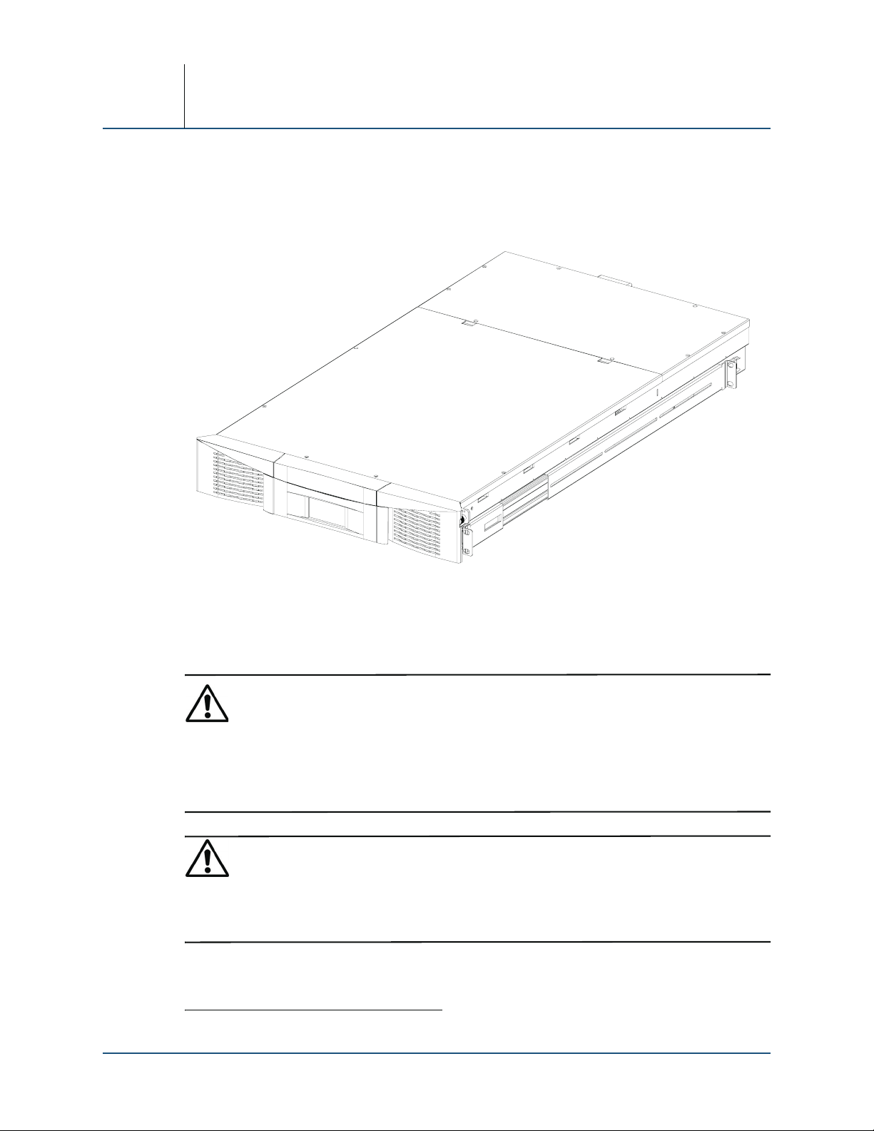
This section provides introductory information about the ARCvault Series 2U (Figure 1-1) tape
archive units—ARCvault 12 Loader1 and ARCvault 24 Library. Included are performance
specifications and characteristics, power requirements, available configurations, and list of
recommended tools and test equipment.
1
1
0
0
C
R
A
1.1 Safety
Observe the following warnings while servicing this system:
Figure 1-1: ARCvault 24 Library
WARNING: The power supplies in your tape archive may produce high voltages and energy
hazards, which can cause bodily harm. Only trained service technicians are authorized to
remove the covers and access any of the components inside the unit.
Die Stromversorgungen Ihres Computers oder Speichersystems erzeugen lebensgefährliche
Hochspannung. Computerabdeckungen dürfen nur von autorisierten Servicetechnikern entfernt
werden, der Zugang zu den Komponenten im Innern des Computers ist ausschließlich
autorisierten Servicetechnikern vorbehalten.
WARNING: Due to the weight of the unit, it is recommended that at least two people be used to
lift the unit out of the box to prevent injury.
Wegen des großen Gewichts der Einheit ist es empfehlenswert, dass beim Herausheben aus
dem Verpackungskarton mindestens zwei Personen beteiligt sind, um somit köperlichen
Verletzungen vorzubeugen.
1 Unless otherwise noted, the ARCvault 12 Loader is included for all generic references to an ARCvault library.
10400025-101 10/2006 1–1
Page 12
Section 1
WARNING: It is recommended that a mechanical lifter (or at least two people) be used to raise
and align the library to prevent injury during the installation into the rack.
Es wird empfohlen, dass zum Anheben und Ausrichten der Library ein mechanisches
Hebegerät (oder ein Minimum von zwei Personen) eingesetzt wird, um körperlichen
Verletzungen bei der Installation ins Rack vorzubeugen.
WARNING: Neither the touch screen nor the power switch completely shuts off power to the
library. To reduce the risk of electrical shock or damage to the equipment, unplug the power
cord.
Die Library lässt sich weder durch die Bedienung des Tastbildschirms, noch des
Betriebsschalters völlig ausschalten. Stecken Sie das Netzkabel aus, um das Risiko eines
elektrischen Schlags zu vermeiden.
Library maintenance may involve exposure to electrical shock or possible damage to the unit.
Before servicing the library, be aware of possible hazards and take necessary precautions. Refer
to the product documentation for additional notes, cautions, and other alerts.
1.2 General Description
The ARCvault loaders and libraries deliver tape backup and archive capabilities to small- and
mid-size IT environments that need to effortlessly protect large amounts of data. The combination
of high capacity and simplicity make the ARCvault family ideal for organizations looking to
implement both disk and tape for superior data protection.
1.3 Version Control
The table below shows the different versions of this service manual. This version is the last
version shown in the table:
Table 1-1: Service Manual Released Versions
Version Number Date Released Changes from Previous Version
10400025-101_A October 30, 2006 Initial Release for ARCvault firmware version 1.57.
1.4 ARCvault Models Covered
• ARCvault 12 Loader with full-height LTO3 SCSI tape drive (OV-ARC101003)
• ARCvault 12 Loader with half-height LTO2 SCSI tape drive (OV-ARC101001)
• ARCvault 24 Library with full-height LTO3 SCSI tape drive (OV-ARC101004)
• ARCvault 24 Library with half-height LTO2 SCSI tape drive (OV-ARC101002)
1–2 10400025-101 10/2006
Page 13

1.5 Specifications
1.5.1 Physical Specifications
Library Configuration
Maximum number of tape cartridges • 12 (ARCvault 12)
Number of media magazines • 1 (ARCvault 12)
Slots per magazine 12
Number of Drives 1 full-height or half-height drive (upgradable to 2
Number of I/E Element Slots
Capacity
Native capacity TB (LTO-3 / LTO-2) 4.8 / 2.4 (ARCvault 12)
Max. compressed
Performance
Native / Compressed† LTO-2 transfer rate (GB/hr) 86.4 / 172.8
Native / Compressed
Dual half-height drives
Native / Compressed
Interfaces
SCSI HD 68
Ethernet RJ-45
Serial RJ-11
LCD Touch Screen
Dimensions 2.5” x 1.25” (6.4cm x 3.2cm)
Type Pressure-sensitive blue and light-gray screen
Resolution 128 x 64 pixels @ 50 dpi
Physical Dimensions
Dimensions (H x W x D) 3.475 x 18.9 x 34.25 in. (8.6 x 48.3 x 87.0 cm)
Weight Empty 43 lbs (20kg)
Base Configuration Shipping Weight 45 lbs (21kg)
Fully Configured Weight with Maximum Number
of Magazines and Drives (No Cartridges)
*. ARCvault 24 only.
†. Assumes compression ratio of 2:1. Actual performance may vary with the application.
*
†
storage TB (LTO-3 / LTO-2)
†
LTO-2 transfer rate (GB /hr)
†
LTO-3 transfer rate (GB/hr) 216 / 432
General Information
•24 (ARCvault 24)
•2 (ARCvault 24)
half-height drives in the ARCvault 24)
0, 1, or 12, depending on configuration
9.6 /4.8 (ARCvault 24)
9.6 /4.8 (ARCvault 12)
19.2 / 9.6 (ARCvault 24)
172.8 / 345.6
• ARCvault 12: 52 lbs. (23.5kg)
• ARCvault 24: 57.5 lbs. (26kg)
10400025-101 10/2006 1–3
Page 14

Section 1
1.5.2 Technical Information
Operational Specifications
Mount time Less than 60 seconds, estimated
Dismount time (excluding rewinding) Less than 60 seconds, estimated
Inventory time (full including tape drives) Less than 3 minutes
Rewind time (maximum / average) 98 / 49 sec
Power Consumption
Idle State 80 Watts / 223 BTUs / 288 KJ
Average Running State 80 Watts / 223 BTUs / 288 KJ
Peak Power 165 Watts / 563 BTUs / 594 KJ
Voltage
Input Voltage, Low
Input Voltage, High
Input Frequency 50-60 Hz
AC Power Input One IEC320-C14 type rear-panel receptacle
BTU Heat Load
Maximum, one drive 69.0 BTU/hour
Maximum, two drives
*. The low voltage nominal will be 110 VAC and the high voltage nominal will be 220 VAC.
†. Based on 3.415179 BTU/watt.
‡. ARCvault 24 only.
*
*
†
‡
100-120 VAC ±10%
200-240 VAC ±10%
96.9 BTU/hour
1.5.3 Reliability and Safety
Reliability
Mean time between failures (MTBF) More than 250,000 hours
Maximum swaps before failure (MSBF) More than 1,000,000 cartridge swaps
Design life 7 years
Mean time to repair (MTTR) Less than 30 minutes
Safety Standards
NRTL - US IEC60950-1, Standard for Safety of Information
NRTL - Canada CAN/CSA-C22.2 No. 950, Standard for Safety of
CE Marking (European Union) Low Voltage Directive, 72/23/EEC, European Union
TÜV GS Mark (Germany) EN60950, (IEC950) Standard for Safety of
Technology Equipment
Information Technology Equipment
Information Technology Equipment, 3
rd
addition
1–4 10400025-101 10/2006
Page 15

1.5.4 Temperature, Humidity and Altitude
Operating
Dry Bulb Temperature -10°C to 40°C
Temperature Gradient 1°C / min. (across the range)
Temperature Shock 15°C (over 2 min.)
Wet Bulb Temperature 26°C
Relative Humidity 15% to 85% (noncondensing)
Humidity Gradient 10% / hr.
Power On—No Tape Loaded (Unpacked—72 hours)
Dry Bulb Temperature 0°C to 50°C
Temperature Gradient 15°C / hr. (across the range)
Temperature Shock 15°C (over 2 min.)
Wet Bulb Temperature 30°C
Relative Humidity 10% to 95% (noncondensing)
Humidity Gradient 10% / hr.
Non-Operating—Long Term (Packed or Unpacked)
Dry Bulb Temperature -40°C to 60°C
Temperature Gradient 20°C / hr. (across the range)
Temperature Shock 15°C (over 2 min.)
Wet Bulb Temperature 30°C
Relative Humidity 5% to 95% (noncondensing)
Humidity Gradient 10% / hr.
Transit—Short Term (Packed 7 Days)
Dry Bulb Temperature -40°C to 60°C
Temperature Gradient 25°C / hr. (across the range)
Temperature Shock 15°C (over 2 min.)
Wet Bulb Temperature 30°C
Relative Humidity 5% to 95% (noncondensing)
Humidity Gradient 10% / hr.
General Information
1.5.5 Shock
Operating (Within Spec—No Damage)
Peak Acceleration 31 Gs ±5%
Duration 2.6ms
Wave Shape 1/2 sine pulses
Application X,Y,Z axes
Non-Operating, with Tape Cartridges Removed (Unpacked—No Damage)
Peak Acceleration 71 Gs ±5%
Duration 2ms
Wave Shape 1/2 sine pulses
10400025-101 10/2006 1–5
Page 16

Section 1
1.5.6 Vibration
Application X,Y,Z axes
Transit/Storage (Packed—No Damage)
Peak Acceleration 30 Gs
Duration 30ms
Wave Shape 1/2 sine pulses
Application X,Y,Z axes
Physical Drop Test (Packed—No Damage)
Drop Test Distance 30 in.
Application Per TAPPI T802om-91
Operating Sine Test (Within Spec—No Damage)
Frequency Range 5–500–5Hz
Amplitude 0.1 inch, double amplitude, 0.25 G
Dwell and Duration 15 min. for a total of 1.5 hours
Wave shape Sinusoidal, 1 octave/min.
Application X,Y,Z axes, 2 sweeps per axis
Operating Random Test (Within Spec—No Damage)
Frequency Range 5–500Hz
Profile Level 0.27 GRMS
Duration 30 min. per axis
Random Tests Per ASTM D3580
Application X,Y,Z axes
Non-Operating Sine Test (Unpacked—No Damage)
Frequency Range 5–1000–5Hz
Amplitude 0.1 inch, double amplitude, 1.0 G
Dwell and Duration 15 min. for a total of 1.5 hours
Wave shape Sinusoidal, 1 octave/min.
Application X,Y,Z axes, 2 sweeps per axis
Non-Operating Random Test (Unpacked—No Damage)
Frequency Range 5–250Hz
Profile Level 1.54 GRMS
Duration 30 min. per axis
Random Tests Per ASTM D3580
Application X,Y,Z axes
Truck Transit Test (Packed—No Damage)
Frequency Range 5–200Hz
Profile Level 1.146 GRMS
Duration 30 min. per axis
Random Tests Per ASTM D4728-95
Application X,Y,Z axes
1–6 10400025-101 10/2006
Page 17

Air Transit Test (Packed—No Damage)
Frequency Range 5–300Hz
Profile Level 1.146 GRMS
Duration 30 min. per axis
Random Tests Per ASTM D4728-95
Application X,Y,Z axes
1.5.7 Electromagnetic Emissions
Agency Standards
FCC US Std. 47 CFR, Part 15 Rules, Class A. Notation on
Industry Canada (ICES) Industry Canada Rules, ICES-003, Class A. Notation
CE Marking (European Union) EMC Directive, 89/336/EEC Laws, relating to
VCCI (Japan) Class A per CISPR 22, Japan. VCCI statement on
BSMI (Taiwan) CNS: 13438, Taiwan. Class A
General Information
Product
on product
electromagnetic compatibility, European Union
EN55022, Standard, RFI limits, Information
Technology Equipment, Class A EN55024,
Information Technology Equipment, Immunity.
product
10400025-101 10/2006 1–7
Page 18

Section 1
1–8 10400025-101 10/2006
Page 19
2
SECTION
System Overview
2.1 Installation
WARNING: Due to the weight of the unit, it is recommended that at least two people be used to
lift the unit to prevent injury.
2.1.1 Shipping Tie-Down Wire
CAUTION: A tie-down wire holds the shuttle and robotics in place for shipment and MUST be removed before
operating the unit. Failure to remove this tie-down will result in damage to the internal robotics and
catastrophic failure of the unit.
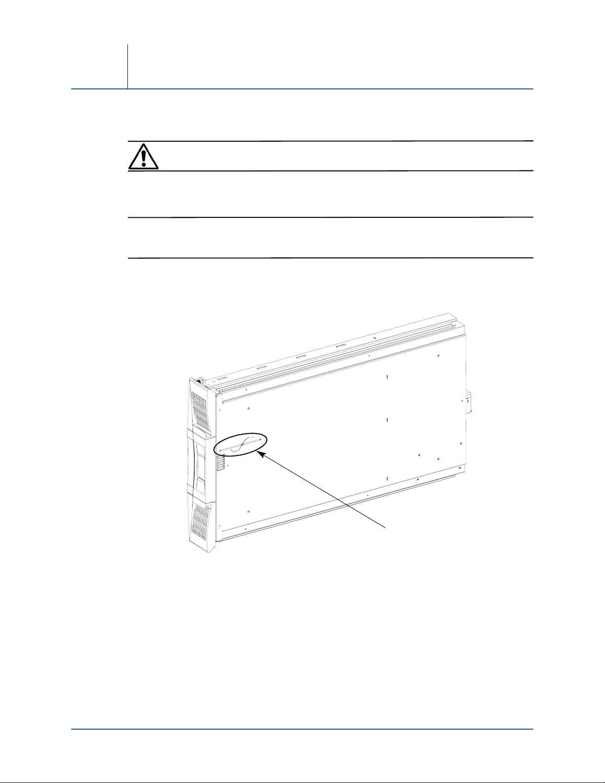
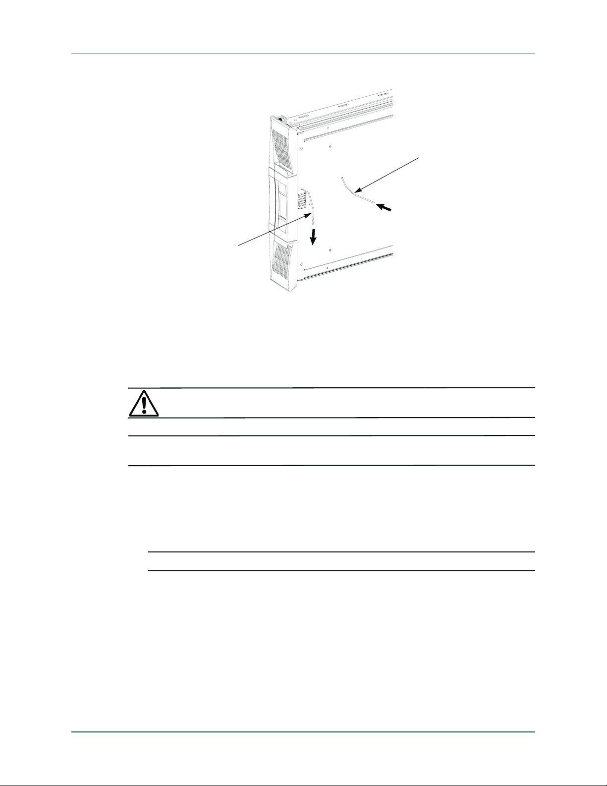
2.1.1.1 Tie-Down Removal
1. Turn the library on its side (Figure 2-1).
8
4
0
0
C
R
A
Robotics Tie-Down
(Must Be Removed)
Figure 2-1: Location of Robotics Tie-Down Wire Underneath Library
2. Untwist the tie-down wire underneath near the front center.
3. At the wire end closest to the center of the unit, push (Figure 2-2) part of the wire up into
the unit.
10400025-101 10/2006 2–1
Page 20
Section 2
Push In
7
5
Pull Out
0
0
C
R
A
Figure 2-2: Tie-Down Removal
4. Using the wire end closest to the front, gently pull the wire out.
If necessary, feed the other wire end up into the unit as you pull out the front end.
5. Save the tie-down wire in case you ever need to ship the unit.
2.1.1.2 Tie-Down Reinstallation for Shipment
WARNING: To reduce the risk of electric shock or damage to equipment, disconnect the power
by unplugging the power cord.
CAUTION: Do NOT turn the library upside down onto its top or allow the front bezel to contact the table if on
its side.
1. Remove and retain the six screws from the front top cover of the empty chassis.
2. Lift the front edge of the cover and pull it slightly forward to release the tabs in the rear. Set
the cover aside.
3. Verify that the shuttle is in the Home position (facing the bottom front slot of the right
magazine).
IMPORTANT: If the shuttle is not in the Home position, contact Overland Technical Support.
4. Position the library so there is space underneath the front 8 inches (20cm) of the unit.
This allows room for the tie-down to exit the chassis and be twisted together.
5. Insert one end of the saved tie-down into the front tie-down hole and the other end into the
rear tie-down hole (Figure 2-3).
Route the tie-down wire between the black motor cable and the body of the shuttle.
2–2 10400025-101 10/2006
Page 21

System Overview
Tie-Down
Holes
Shuttle
Top
Motor Cable
Figure 2-3: Tie-Down Hole Locations (Top View)
6. From the bottom, pull both ends of the tie-down wire simultaneously until tight, and then twist
them together (Figure 2-4).
8
4
0
0
C
R
A
Figure 2-4: Tie-Down in Place
7. Using the six retained screws, reattach the front top cover.
2.1.2 Rack Considerations
An ARCvault library comes with the inside slide rails attached to the unit. The provided rail kit is
used to attach the outside rails to the rack to support the unit. This rail kit is not intended to be
used on a threaded rack.
WARNING: It is recommended that a mechanical lifter (or at least two people) be used to raise,
align, and lower the unit to prevent injury during the installation into or removal from the rack.
2.1.2.1 Installing an ARCvault Library
1. Locate and mark the holes for the outside rails and retaining screws.
a. Starting with the right front flange at the bottom of the rack (or from the top of a
previously mounted component), locate the first set (Figure 2-5) of three holes with equal
gaps of 5/8 inch (1.6cm).
10400025-101 10/2006 2–3
Page 22

Section 2
Right Front Flange
Retaining Screw
Hole Mark
5/8" (1.6cm)
2U
First
Hole
Set
1/2" (1.3cm)
5/8" (1.6cm)
5/8" (1.6cm)
0
3
0
0
C
R
A
Top Rail
Hole Mark
Bottom Rail
Hole Mark
Figure 2-5: Holes Used for Attaching Rails
b. Mark the top and bottom holes of the set for the rail screws.
c. Mark the second hole above the set for the retaining screw.
d. Repeat Steps a–c for the left side.
2. Repeat Step 1 for the rear holes.
CAUTION: Be sure rear holes are horizontally in line with the front holes to assure the unit remains
level.
3. Adjust the rear mounting bracket to fit inside the rack flanges.
a. Remove and retain the two adjustment nuts and washers on the right outside rail.
b. Move the rear bracket so that the two PEM studs are in different slots (Figure 2-6).
• Use the two rear slots for a 24" deep rack.
• Use the two center slots for a 30" deep rack.
• Use the two front slots for a 36" deep rack.
Front Bracket & Rail Assembly
Adjust Rear Bracket to Fit
3
6
0
0
C
R
A
PEM Studs & Lock Nuts
Figure 2-6: Outside Rail Adjustment for 30" Rack
c. Loosely replace the retained washers and screws.
d. Repeat Steps a–c for the left rail.
4. Using the eight SEMS screws and four bar nuts provided, attach the rails inside the flanges
(Figure 2-7).
NOTE: To ensure proper alignment, the bar nut corner notches must face away from the rail.
a. Attach the right outside rail inside the marked locations (Figure 2-7) of the right front
and right rear flanges.
b. Tighten the rail adjustment nuts on the outside edge of the rail.
c. Repeat Steps a–b for the left outside rail.
2–4 10400025-101 10/2006
Page 23

Front Flanges
System Overview
Rear Flanges
Bar Nut
2
6
0
0
C
R
A
Adjustment Nuts
Clip Nut
Figure 2-7: Attaching Outside Rails
5. Attach two clip-nuts to the retaining screws holes on the front rack flanges.
6. Move the slides all the way forward to assist with the installation of the unit.
7. Lift the ARCvault unit and, aligning the inner rails into the outer rails on the rack, gently
slide it into the rack until the rail stops engage. Release the rail stops and continue sliding
the unit into the rack until the front panel touches the front flanges.
NOTE: Early models require a tool (such as a screwdriver) to release the safety catches.
8. Tighten the two retaining screws behind the doors (Figure 2-8) to secure the unit.
Retaining Screw
Figure 2-8: Tighten Retaining Screws to Rack
9. Attach all network cables and power cords (see “Attaching Cables” on page 2-6).
10400025-101 10/2006 2–5
Page 24

Section 2
2.1.2.2 Removing ARCvault Library for Service
1. Power off the unit and remove the power cord.
See “Power-Off Process” on page 2-8 for details.
2. Label and remove all wiring and cables in the rear.
3. Loosen the two retaining screws in the hinge area inside the doors.
4. Close the doors and grasp the unit by the metal bracket behind the door hinges.
CAUTION: Do not pull on the doors as this can damage or break them.
5. Gently pull the unit a few inches out of the rack to expose the case.
6. Grasp the library case and slide the ARCvault unit outward until the rail stops engage.
7. Press the safety catches on each rail to release them.
NOTE: Early models require a tool (such as a screwdriver) to release the safety catches.
8. Using two people or a mechanical lifter, carefully slide the unit the rest of the way out and set
it on a secure surface.
2.2 Attaching Cables
All the cables that connect the ARCvault unit to your host system and power source are located at
the rear of the library (Figure 2-9).
Drive Cover
SCSI Ports
Ethernet Serial
USB (not implemented)
AC ReceptaclePower Switch
Figure 2-9. ARCvault Rear Connections and Power Switch
An ARCvault library comes with a single tape drive already installed and ready to be connected to
the network (Figure 2-10).
NOTE: ARCvault 24 units that come configured with one half-height drive can accommodate a second
half-height drive (available separately). The external cabling is the same as a single drive library.
8
0
0
0
C
R
A
2–6 10400025-101 10/2006
Page 25

SCSI Cable
Power Cord
System Overview
5
7
0
0
C
R
A
1. Connect the LVD SCSI cable to one of the SCSI ports and the other end to your system.
2. Attach the SCSI terminator to the remaining open SCSI port.
3. Plug the host network connection into the Ethernet port.
4. Plug the power cord into the AC receptacle and the other end into a power source.
2.3 Power Management
WARNING: Neither the touch screen nor the power switch completely shuts off power to the unit.
To reduce the risk of electrical shock or damage to the equipment, remove the power cord.
While powering on the unit, holding the rear Power button more than 10 seconds will put the unit
into a maintenance mode. To exit the maintenance mode, recycle the power normally.
SCSI Terminator
Ethernet
Figure 2-10: ARCvault Basic Cabling
Front: Tap Here Rear: Press Here
2
2
0
0
C
R
A
8
0
0
0
C
R
A
Figure 2-11: Power-On Points
2.3.1 Power-On Process
1. Verify the power cord is plugged in.
2. Start the power-on process (Figure 2-11).
• From the front, tap the OCP.
• From the rear, press and release the Power switch.
10400025-101 10/2006 2–7
Page 26

Section 2
3. The POST process begins and displays the Startup screen (Figure 2-12).
Figure 2-12: POST Startup Logo Screen
NOTE: You can press the Continue button on the Startup screen to view the Default screen. However,
the ARCvault will not allow any changes to its settings until POST completes.
After approximately 50 seconds, the unit automatically displays the Default menu screen
(Figure 2-13).
After approximately 3 minutes, when the unit has completed its POST (including an inventory
of cartridges), it is ready for use.
2.3.2 Power-Off Process
At the OCP, press Power > Power Off to have the library perform a controlled shutdown.
Alternately, pressing and holding the Power button on the rear panel for 4 seconds shuts off power
without parking the shuttle and completing tasks.
2.4 Interfaces
There are two ways to interact with an ARCvault library: the Operator Control Panel (OCP) and
the Remote Management Utility (RMU).
2.4.1 Operator Control Panel
The OCP touch screen provides an easy way to make common configuration changes and control
access to the media. The following is a basic list of operational procedures and general instructions
for using the OCP touch screen.
• Virtual buttons are represented on the screen as rectangles with labels such as “Status.” Press
inside the rectangle to activate the button’s feature or submenu.
• A keyboard or set of option buttons is automatically displayed when numbers need to be
entered or specific selections are required.
• If more options are available than can fit on the screen, arrow buttons are displayed on the
bottom so you can scroll through the options. Only one arrow is shown when you reach the end
or beginning of the list.
Figure 2-13: OCP Default Screen
NOTE: The Status screen, Help screen, and all message screens use scroll bar arrows on the right side
in place of the Up/Down arrows.
2–8 10400025-101 10/2006
Page 27

System Overview
• A Back or Cancel button is always available on the bottom right of all secondary or lower
screens to return you to the previous screen.
• When the library is powered off but still plugged in, the OCP glows blue. Tapping the OCP
starts the power on cycle.
2.4.1.1 ARCvault OCP Software Maps
Figure 2-14: ARCvault 12 OCP Software Map
10400025-101 10/2006 2–9
Page 28

Section 2
Figure 2-15: ARCvault 24 OCP Software Map
2.4.2 Remote Management Utility
The ARCvault RMU is an interface built into the ARCvault library and provides remote access to
and configuration of the library through an Ethernet port. It hosts a dedicated, protected Internet
site that can be accessed by a web browser using the IP address assigned to the ARCvault unit. This
is accomplished either from a PC connected to your network or via the World Wide Web using the
default HTTP port 80.
NOTE: If connecting a laptop directly to the unit to access the RMU site, use a crossover Ethernet cable
plugged into the Ethernet port at the rear of the unit.
2–10 10400025-101 10/2006
Page 29

System Overview
The RMU default Login page uses Java-based encrypted HTTP authentication that encrypts the
password sent to the unit. The RMU firmware uses standard HTML-based pages that are served to
a web browser. The pages consist of two frames—a top navigational frame and a lower data frame.
2.4.2.1 ARCvault RMU Software Map
Figure 2-16: ARCvault 12 RMU Software Map
10400025-101 10/2006 2–11
Page 30

Section 2
Figure 2-17: ARCvault 24 RMU Software Map
2.5 Password Protection
For added protection, the library lets you assign different levels of security using passwords:
• The OCP touch screen has User and Service security using 4-digit numeric passwords.
• The RMU offers Operator and Administrator security using 12-digit alphanumeric characters.
The default Administrator password is “2” while the default Operator password is “1.”
• An additional level of security is built in to both interfaces for factory technicians.
2–12 10400025-101 10/2006
Page 31

System Overview
Table 2-1 shows the different OCP security levels, the access point that prompts for a password,
and the scope of access.
Table 2-1: ARCvault OCP Security Levels
Typ e Level Controls this Access Description
User 1 • Power > Power Off Library
• Power > Reboot Library
• Mag Access
•Move Media
Service 2 • Edit Opts > Library
•Edit Opts > Passwords
•Edit Opts > SCSI/FC
• Edit Opts > Network
•Utilities > Service
•Utilities > Diagnostics
Factory 4 • Utilities > Factory Factory technician use only.
NOTE: Each security type controls a specific group of OCP options. For example, adding a User password
does NOT protect Service-level options. However, a higher level of security permits access to all
lower-level functions, such as Service-level security allows access to all User-level functions.
Controls access to the power, media magazines,
and the movement of the media inside the unit.
Controls access to most of the utilities and the
editing of options.
2.6 Tape Magazines
To help manage the tape media, the cartridges are stored in 12-slot magazines that are removable.
This provides an easy way to exchange tapes and can also double as off-site storage unit.
2.6.1 Slot Management
To help manage the tape cartridge inventory, the individual slots of the magazines are numbered.
The number sequencing is from the bottom to the top, front to back. When a I/E Element is
configured, those slots are numbered separately.
The ARCvault 12 has one magazine located on the right side. Figure 2-18 shows the slot numbering
sequence for the magazine.
Right Magazine
Figure 2-18. ARCvault 12 Normal Slot Numbering
6312 9
11 8 5 2
10 7 4 1
Handle
0
2
0
0
C
R
A
10400025-101 10/2006 2–13
Page 32

Section 2
In the ARCvault 24, when no I/E Element is enabled (Figure 2-19), the slot numbering starts in the
left magazine and continues with the right magazine.
91236
25811
Left Magazine
14710
Handle
Handle
18 1524 21
Right Magazine
23 20 17 14
22 19 16 13
0
2
0
0
C
R
A
Figure 2-19: ARCvault 24 Normal Slot Numbering
When a single-slot I/E Element is enabled on an ARCvault 24, the first slot is used for it and labeled
“ie.” This causes the regular slot numbering to start from the second slot, making it slot 1 (Figure 2-
20).
81125
Left Magazine
Handle
0
2
0
0
C
R
A
Handle
Right Magazine
14710
ie 3 6 9
I/E Element
17 1423 20
22 19 16 13
21 18 15 12
Figure 2-20: Slot Numbering with Single-Slot I/E Element
With the entire left magazine configured as a I/E Element, the slots are numbered 1–12 and the
magazine name changes from “Left Mag” to “I/E Mag” (Figure 2-21). The regular slot numbering
(Slot 1) starts with the first slot of the right magazine.
91236
25811
I/E Element
(Entire Left Mag.)
14710
Handle
Handle
6312 9
Right Magazine
(Normal Slots)
11 8 5 2
10 7 4 1
Figure 2-21: Slot Numbering with Full-Magazine I/E Element
0
2
0
0
C
R
A
2–14 10400025-101 10/2006
Page 33

System Overview
2.6.2 I/E Element
The ARCvault 24 is configurable so that you can add or remove tape cartridges without stopping
the library using the I/E Element. This feature is available only on the left magazine. There are two
variations:
• Single-Slot I/E Element – in this default configuration, only the bottom front slot of the left
magazine is used as a I/E Element.
• Full-Magazine I/E Element – the entire left magazine is used as a I/E Element.
NOTE: Opening the left door immediately deactivates the robotics so that the I/E Element can be
removed. When the door is shut again, the library immediately reinventories the I/E Element
(either the single slot or all 12 slots depending on the configuration) before continuing.
2.6.2.1 Single-Slot I/E Element
Configuring your ARCvault to have a single-slot I/E Element provides a maximum benefit with a
minimum impact on operations since only one slot is dedicated to that purpose. The single-slot
I/E Element can be removed by pressing both release tabs together and pulling the handle
(Figure 2-22).
I/E Element Magazine Release Tabs Standard Magazine
Figure 2-22: I/E Element Magazine Location
CAUTION: When removing a single-slot I/E Element with a tape cartridge in it, be careful to keep the slot tray
level. Tilting the I/E Element can result in the tape falling out and possibly being damaged.
4
2
0
0
C
R
A
10400025-101 10/2006 2–15
Page 34

Section 2
The bottom front slot and handle that form the single-slot I/E Element assembly is removed
(Figure 2-23). The remainder of the magazine (11 slots) stays in the library.
4
0
0
0
C
R
A
3
0
0
0
C
R
A
Figure 2-23: Removing Single-Slot I/E Element
Once the I/E Element is out of the unit, media can be removed or inserted (Figure 2-24).
Tape Ca r t ridg e
Front
Handle
2
0
0
0
C
R
A
I/E Element
Figure 2-24: Single-Slot I/E Element With Tape
2.6.2.2 Full-Magazine I/E Element
In this configuration, the entire left magazine is dedicated as an I/E Element, allowing 12
cartridges to be exchanged without stopping the library. This is useful when backing up large
amounts of data requiring numerous tapes to be exchanged before job completion.
CAUTION: Keep a loaded magazine level. Tilting the magazine can result in the tapes falling out and possibly
being damaged. Also, don’t hold a magazine by just the handle; use both hands to support it.
Once unlocked, a full-magazine I/E Element is removed by just pulling the magazine handle. The
release tabs are not used.
2–16 10400025-101 10/2006
Page 35

3
SECTION
Troubleshooting and FSCs
This section provides some troubleshooting information and a list of Fault Symptom Codes (FSCs)
for the ARCvault library that may be displayed when there is a possible malfunction. A descriptive
message and instructions for clearing the fault accompany each FSC.
3.1 Possible Problems
An incorrect installation or configuration can cause platform problems. In such a case, the library
appears to be operating normally, but data can not be interchanged. An error code may be displayed
on the OCP touch screen. To resolve an error caused by this type of problem, check your installation
and configuration setup. Refer to your user guide for information on how to correctly install and
configure the library.
General drive errors usually result from a miscommunication between the library and tape drive, or
a mechanical malfunction within the library.
Both platform problems and general drive errors display an FSC and an error message on the OCP
touch screen and the RMU Library Health Status table. Use the FSC to determine a recovery
procedure or report errors to your service provider.
3.1.1 Sample Screens
When a malfunction occurs, an error message is displayed on the OCP touch screen:
Use the arrow buttons on the right to scroll down to see all the message.
The same information is available in the RMU. Click the Status tab and choose the Library Health
option to view the following table:
3.2 Error Recovery
To simplify the error recovery process, follow this General Troubleshooting procedure (Figure 3-3)
using the table and Error Recovery Procedure (ERP) flowcharts to troubleshoot the problem.
Figure 3-1: Sample OCP Error Message Screen
Figure 3-2: Sample RMU Error Message in Library Health Table
10400025-101 10/2006 3–1
Page 36

Section 3
Using the Fault Code Table, note
number of the Err or Recovery
Procedure (ERP).
ERP = 1?
Yes
No
ERP = 2?
Yes
No
ERP = 3?
Yes
No
ERP = 4?
Yes
Customer repor ts either a backup application failed or a
Fault Symptom Code (FSC) is being displayed .
ERP = 1
Yes
FSC listed in
Fault Code Table?
No
Yes
START
FSC listed in
ERP=2
Fault Code Table?
No
ERP=3
New FSC
Found
Note fault code and error
message. Retrieve library trace.
Attempt to run standalone
cartridge-cycle and dr ive -cycle
diagnostics on library.
No
Passed?
Yes
Attempt to run read/write tests to
tape drive with known good
media.
No
ERP = 5?
No
ERP = 6?
No
ERP = 7?
No
ERP=8
ERP=4
Yes
ERP=5
Yes
ERP=6
Yes
ERP=7
Figure 3-3: General Troubleshooting Procedure
3.2.1 FSC/ERP Cross-Reference Table
Table 3-1 lists the possible FSCs and accompanying messages and descriptions. Use the listed
ERP number to determine the correct procedure to use for resolving the problem:
Drive
R&R
Level 3
Escalation
No
Passed?
Yes
Verify system and application is at
appropriate r evision levels and
has no defective hardware or
No
cabling .
Problem
Resolved?
Yes
(Resume normal operation)
END
3–2 10400025-101 10/2006
Page 37

Troubleshooting and FSCs
Table 3-1: FSC/ERP Cross-Reference
FSC Message ERP Description
101 “Serial Port Initialization Error” 1 The serial port controller on the library controller
card failed to initialize during POST.
306 “NVRAM Update Error” 1 The Non-Volatile RAM did not update during POST.
402 “Non-Volatile Configuration Save
Error”
404 “Drive Configuration Error Full-
height drive Is incorrectly cabled.”
405 “Drive Initialization Error” 2 The tape drive did not initialize correctly during
501 “Bar Code Reader Not Detected” 1 The bar code reader was not detected during POST.
901 “OS Critical Error” 1 The library firmware encountered a critical internal
902 “Network Catastrophic Error” 1 The RMU firmware encountered a critical internal
0A01 “Invalid Ethernet (MAC) Address” 1 An invalid MAC address was encountered when the
0A02 “Invalid IP Subnet Mask
(255.255.255.255)”
0C01 “Exception Error” or
“Firmware Exception”
1001 “SCSI Firmware Error” 1 The library SCSI firmware encountered a critical
1011 “SCSI Initialization Error.
None of the attached drives have
ADI Bridging Enabled.”
2001 “Invalid Control Command” 1 The library control firmware detected an invalid
2004 “Loader Not Ready” 1 The library control firmware detected that the
2008 “Illegal Move” 1 The library control firmware detected an illegal
2009 “Door Open” 4 The library door/switch is open and all robotics
200F “Drive Media Removal Prevented” 5 A host move medium command was attempted but
2010 “Control Firmware Error” 1 The library control firmware detected a critical
20b0 “Unknown exchange for the async
message”
3000 “Motor Fault Condition, see trace
for details”
1 The Non-Volatile RAM configuration did not save
correctly during POST.
2 The library detected that the wrong serial cable is
connected to the full height drive.
POST.
error.
error during network initialization.
library was initializing the RMU ethernet port.
3 An invalid IP subnet was detected when initializing
the RMU ethernet configuration.
1 The library firmware encountered a critical internal
error.
internal error.
2 The library SCSI firmware was not able to initialize
because an ADI-enabled drive was not detected.
internal command.
loader hardware was not ready.
move attempted by an internal process.
operations are suspended until this condition is
cleared.
the library detected that the drive is in a prevent
medium removal state from the host.
internal error.
1 The library interprocess communications firmware
detected a critical internal error.
1 A motor fault condition was detected and the
library trace file is required for additional error
detail.
10400025-101 10/2006 3–3
Page 38

Section 3
Table 3-1: FSC/ERP Cross-Reference
FSC Message ERP Description
3002 “Picker Tach Errors” 1 The library picker motor has reported excessive
tach errors.
3011 “Bin Fetch Failure” 6 The library failed to fetch a cartridge from a slot
and all retries were exhausted.
3012 “Bin Stow Failure” 6 The library failed to stow a cartridge to a slot and all
retries were exhausted.
3013 “Drive Fetch Failure” 7 The library failed to fetch a cartridge from a drive
and all retries were exhausted.
3014 “Drive Stow Failure” 7 The library failed to stow a cartridge to a drive and
all retries were exhausted.
3016 “Drive Status Failure” 2 The library was not able to get status from the drive
serial (ADI) interface during the normal status
check.
301B “Drive Communication Error” 2 The library was not able to communicate with the
drive ADI.
301C “Drive Get General Status Fail” 2 The drive did not return the general status packet
over the ADI.
301E “Drive Unload Fail” 8 The drive did not successfully unload a cartridge
when the library issued the eject command over
the ADI.
3020 “Undefined Config” 2 The library firmware detected an invalid
configuration during a diagnostic operation. This
error usually indicates an internal hardware
problem.
3035 “Drive Unload Prevented” 5 The library was unable to eject the cartridge from
the drive to scan its barcode during an inventory
because the drive is in a prevent media removal
state. The prevent media removal state is set by a
host SCSI command to the drive.
3041 “Loader Received Invalid Cmd” 1 The library loader firmware process detected an
invalid internal command.
3045 “Loader Invalid Drive Number in
Cmd”
3051 “No Cartridges In Library” 4 A cartridge cycle diagnostic was attempted with no
3052 “Too Many Cartridges” 4 A cartridge cycle diagnostic was attempted with no
3053 “Need 3 Cartridges Minimum” 4 A drive cycle diagnostic was attempted with too few
3054 “Need 1 Drive Minimum” 4 A drive cycle diagnostic was attempted but no
3055 “Memory Allocation Error” 1 The library firmware detected an internal memory
305b “Diag Fetch, Drive not loaded” 6 The drive cycle diagnostic attempted to fetch a
1 The library loader firmware process detected an
invalid drive number in an internal command.
media in the library.
empty slots in the library.
cartridges in the library.
drives were detected.
allocation error.
cartridge from the drive and detected the drive in
an unexpected not loaded state.
3–4 10400025-101 10/2006
Page 39

Troubleshooting and FSCs
Table 3-1: FSC/ERP Cross-Reference
FSC Message ERP Description
305f “Invalid bin number” 1 During cartridge cycle or drive cycle diagnostics,
the library firmware detected an invalid slot
selection. This condition indicates a diagnostic
firmware error.
3060 “Cart blocking vertical” 6 The library detected an unexpected cartridge
ejected from the drive when the shuttle is not in
front of the drive. This condition prevents the
vertical robotics movement and requires manual
intervention.
3061 “Unable to Complete Homing
Algorithm”
3074 “Drive Eject Failed” 7 The library issued an eject command over the ADI
3075 “Drive Eject Failed” 7 The library issued an eject command over the ADI
3078 “Diag get drive status failed” 2 The library diagnostic firmware failed to get ADI
3079 “Diag get drive status failed” 2 The library diagnostic firmware failed to get ADI
3082 “Drive Stow Fail, Media Returned to
Source”
3083 “Drive Stow Fail, Media Remains in
Drive”
3084 “Unsupported Drive for Requested
Operation”
308F “No Retry Fault on Fetch/Stow” 1 A robotics fetch stow operation failed and no retry
30b0 “Mail Slot Load/Unload Error” 6 The library was unable to fetch/stow the import/
3100 “Picker Jammed” 7 The library detected a jam condition with the picker
3101 “Picker Overtraveled Stall” 7 The library detected an unexpected overtravel
3102 “Flex cable failure” 1 The library was unable to extend the picker due to a
3115 “Picker Retraction Jam” 7 The library was unable to retract the picker motor
3200 “Shuttle Jammed” 7 The library shuttle motor was stalled/jammed
3305 “Cart sense switch failed” 6 The library did not detect the cartridge sense
6 The library could not complete the vertical homing
algorithm. This usually indicates an obstruction
(such as, a cartridge in the bottom of the chassis or
other impediment).
and drive 1 did not successfully eject.
and drive 2 did not successfully eject.
status from drive 1.
status from drive 2.
7 The library was unable to successfully stow a
cartridge to the drive so the cartridge was returned
to the originating slot.
7 The library was unable to successfully stow a
cartridge to the drive but the cartridge was left in
the drive.
2 The library detected an unsupported drive (usually
a hardware error).
was possible.
export slot.
motor.
condition when moving the picker motor to a
position (stall was expected).
possible flex cable fracture.
and a jam condition was detected.
during a shuttle move operation.
switch in the shuttle assembly.
10400025-101 10/2006 3–5
Page 40

Section 3
Table 3-1: FSC/ERP Cross-Reference
FSC Message ERP Description
3306 “Cart stuck halfway in shuttle” 6 The library firmware detected a cartridge stuck
halfway in the shuttle - an unrecoverable hardware
condition.
3500 “Vertical Elevator Jammed” 6 The library vertical motor was stalled/jammed
during a vertical move operation.
5015 “Expired Cleaning Cart” 9 The library detected an expired cleaning cartridge
as reported by a drive.
5016 “Not a Cleaning Cart” 9 A clean operation was attempted through the
library menu but the drive reported that it was not a
cleaning cartridge.
503B “Move Command Fail” 9 A library (menu mode) cartridge move operation
failed.
503C “Clean Operation Timeout” 9 A library (menu mode) clean operation failed.
70nn “OCP Control errors” 1 All of these fault codes (7001-70ff) should be
considered library internal firmware errors related
to OCP firmware errors.
8001 “Cartridge load recovery failed.” 8 The drive failed to successfully load the cartridge at
the completion of a library stow-to-drive operation.
8003 “Drive Load did not Complete.” 8 The library stowed a cartridge to the drive but the
drive did not successfully complete the load
operation in the timeout period.
8009 “Drive Load Error” 8 The drive reported a cartridge load error through
the ADI.
800A “Expired Cleaning Cartridge” 9 The drive reported an expired cleaning cartridge
error through the ADI.
800B NEED INFO????
800C “Invalid Cleaning Cartridge” 9 The drive reported an invalid cleaning cartridge
error through the ADI.
800D “Defective Media” 6 The media in the tape drive cannot be used.
8020 “Firmware update failed” 5 Drive firmware update using RMU failed. Retry
update procedure.
A00n “SMX error” 1 All of these fault codes (A001-A0nn) should be
considered library internal firmware problems
related to interprocess task communication errors.
C0nn “RMU Firmware errors” 1 All of these fault codes (C001-C0nn) should be
considered library internal firmware problems
related to RMU firmware failures.
3–6 10400025-101 10/2006
Page 41

3.2.2 Error Recovery Procedures
Use the following 10 troubleshooting ERP flowcharts to diagnose the problem that caused the
FSC. Table 3-2 lists ERP codes and the possible problem area. This list includes only those
procedures that can be safely performed by an end user.
Table 3-2: Error Recovery Procedures
ERP # Possible Problem Area
1 Defective chassis
2 Defective chassis or drive
3 User configuration error
4 User operation error
5 System or application error
6 Defective media or chassis
7 Defective media, chassis, or drive
8 Defective media or drive
Troubleshooting and FSCs
10400025-101 10/2006 3–7
Page 42

Section 3
ERP = 1
Reboot the library and retry the
operation that produced the FSC.
New FSC
Found
New FSC
displayed ?
1. Turn off power to the library.
2. Wait 5 seconds .
3. Power up the library.
4. Retry the operation that
produced the fault code.
New FSC
displayed ?
Chassis
FSC
Same FSC
FSC
Same FSC
R&R
No FSC
No FSC
END
(Resume normal operation)
Figure 3-4: Error Recovery Procedure 1—Defective Chassis
3–8 10400025-101 10/2006
Page 43

ERP=2
Reboot the library and retry the
operation that produced the FSC.
Troubleshooting and FSCs
New FSC
Found
New FSC
displayed ?
1. Turn off power to the library.
2. Wait 5 seconds .
3. Power up the library.
4. Retry the operation that
produced the fault code.
New FSC
displayed ?
Chassis/
Drive R&R
FSC
Same FSC
FSC
Same FSC
No FSC
No FSC
END
(Resume normal operation)
Figure 3-5: Error Recovery Procedure 2—Defective Chassis or Drive
10400025-101 10/2006 3–9
Page 44

Section 3
ERP=3
Instruct the customer on the
correct value to enter for their
librar y configuration.
FSC
displayed ?
Yes
No
Chassis
(Resume normal operation)
END
Figure 3-6: Error Recovery Procedure 3—User Configuration Error
ERP=4
Correct the condition indicated by
the fault code and retry the
operation.
R&R
FSC
displayed ?
Yes
No
Chassis
(Resume normal operation)
END
Figure 3-7: Error Recovery Procedure 4—User Operation Error
3–10 10400025-101 10/2006
R&R
Page 45

ERP=5
Verify that the system, drivers,
and backup application are
supported configurations running
at the current version, then retry
the operation.
Troubleshooting and FSCs
FSC
displayed ?
Yes
No
Level 3
(Resume normal operation)
END
Figure 3-8: Error Recovery Procedure 5—System or Application Error
Escalation
10400025-101 10/2006 3–11
Page 46

Section 3
ERP= 6
Reboot the library to attempt to
clear the fault condition.
New FSC
New FSC
FSC
displayed ?
Same FSC
No FSC
Select a different piece of media
and retry the move operation.
FSC
displayed ?
Same FSC
No FSC
Remove the defective
media from the library.
New FSC
Found
(Resume normal operation)
END
Chassis
R&R
Figure 3-9: Error Recovery Procedure 6—Defective Media or Chassis
3–12 10400025-101 10/2006
Page 47

ERP=7
Reboot the library to attempt to
clear the fault condition.
Troubleshooting and FSCs
New FSC
New FSC
FSC
displayed?
Same FSC
No FSC
Select a different piece of media
and retry the fetch/stow
operation.
FSC
displayed?
Same FSC
No FSC
Remove the defective
media from the library.
Chassis /
Drive R&R
Try the move operation to/
from a different drive or slot.
Was the operation
successful ?
New FSC
Found
(Resume normal operation)
END
Chassis
R&R
Drive
R&R
Figure 3-10: Error Recovery Procedure 7—Defective Media, Chassis, or Drive
10400025-101 10/2006 3–13
Page 48

Section 3
ERP=8
Reboot the library to attempt to
clear the fault condition.
New FSC
New FSC
FSC
displayed ?
No FSC
Retry the drive fetch/stow
operation with a different
piece of media.
FSC
displayed ?
No FSC
Remove the defective
media from the library.
Same FSC
Same FSC
New FSC
Found
(Resume normal operation)
END
Drive R&R
Figure 3-11: Error Recovery Procedure 8—Defective Media or Drive
3–14 10400025-101 10/2006
Page 49

Chassis/
Drive R&R
Remove the suspected tape drive
assembly from the library and
inspect for visible damage.
Troubleshooting and FSCs
Damaged?
No
Dual Drives?
No
Inspect the chassis assembly
interconnect cabling for visible
damage.
Damaged?
No
Yes
Yes
Yes
Swap drives to check
drive vs. position.
Retry the operation.
Replace tape drive
assembly .
Yes
Problem
with same physical
drive?
No
Replace chassis
assembly .
Replace both chassis assembly
and tape drive assembly.
(Resume normal operation)
END
Figure 3-12: ERP Chassis vs. Tape Drive ERP
10400025-101 10/2006 3–15
Page 50

Section 3
Level 3
Escalat ion
Save a Library Trace at
the point of failure. Save all
system informat ion, version
information, system logs , and
application logs .
Notify technical support
and wait for patch.
3.3 Tape Drive Removal
While troubleshooting the library, it may become necessary to remove the tape drive assembly for
examination. Follow this procedure to correctly and safely remove the assembly:
1. At the OCP, press Power > Power Off Library to power down the unit.
2. After the unit has shut down, remove the power cord.
3. At the rear, remove the LVD SCSI cable and terminator from the drive cover SCSI ports
(Figure 3-14).
Apply librar y or system patch .
No
Problem
resolved?
Yes
(Resume normal operation)
Figure 3-13: Level 3 Escalation ERP
END
3–16 10400025-101 10/2006
Page 51

Troubleshooting and FSCs
Drive Cover
Thumbscrews
SCSI Ports
Power Switch
Ethernet
AC Receptacle
Figure 3-14: ARCvault Drive Access
4. Loosen the two thumbscrews on the sides of the drive cover.
5. Remove the drive cover.
a. Gently pull the drive cover out and hold it approximately 2 inches (5cm) below the unit
(Figure 3-15).
b. Unplug the fan wiring from the fan connector.
c. Unplug the SCSI cable from the drives.
d. Set the drive cover aside.
SCSI Cable
Power Cables
Serial Cable
Left Guide
8
0
0
0
C
R
A
Right Guide
Drive Cover
Figure 3-15: Drive Cover SCSI and Fan Cables
6. Unplug the power and serial cables from the drives and position them off to the right.
7. Grasp the guide grips and slide the drive assembly out of the unit.
Reverse the process to reinstall the tape drive assembly.
3.4 Touch Screen Overrides
If calibration or contrast problems exist with the OCP touch screen, it may not be possible to make
changes using the OCP. However, there are overrides that can address these issues.
Fan Cable
Connector
8
2
0
0
C
R
A
10400025-101 10/2006 3–17
Page 52

Section 3
3.4.1 Touch Screen Forced Recalibration
1. Cycle the unit’s power.
2. At the startup screen, press
the following sequence:
a. Upper right corner
b. Lower left corner
c. Upper left corner
d. Lower right corner
3. Following the on-screen
instructions, press the boxed X at the lower left of the screen, and then press the boxed X at
the upper right.
The screen should now be recalibrated and ready to use.
3.4.2 Touch Screen Contrast Reset
1. Cycle the unit’s power.
2. At the startup screen, press
the following sequence:
a. Upper right corner
b. Lower right corner
c. Upper right corner
d. Upper left corner
The screen is returned to the default
setting of 32. Use Setup > Utilities > Diagnostics > Screen Calib to make any changes.
c a
db
d a/c
b
3–18 10400025-101 10/2006
Page 53

4
SECTION
Adding or Replacing Components
There are four components in the ARCvault library that are replaceable:
• Tape Drive
• Drive Cover Assembly (with exhaust fan)
• Media Magazine
• Chassis
Also, in ARCvault 24 libraries with a half-height drive, one component can be added:
• Second half-height drive
4.1 Replacing a Tape Drive
Should the need arise, it is easy to remove and replace an ARCvault tape drive.
WARNING: Neither the touch screen nor the power switch completely shuts off power to the unit.
To reduce the risk of electrical shock or damage to the equipment, remove the power cord.
4.1.1 Remove the Drive Assembly
1. At the OCP, press Power > Power Off Library to power down the unit.
2. After the unit has shut down, remove the power cord.
3. At the rear, remove the LVD SCSI cable and terminator from the drive cover SCSI ports
(Figure 4-1).
Thumbscrews
Drive Cover
4. Loosen the two thumbscrews on the sides of the drive cover.
5. Remove the drive cover.
a. Gently pull the drive cover out and hold it approximately 2 inches (5cm) below the unit
(Figure 4-2).
b. Unplug the fan wiring from the fan connector.
c. Unplug the SCSI cable from the drives.
d. Set the drive cover aside.
SCSI Ports
Figure 4-1: ARCvault Rear Panel
Power Switch
Ethernet
AC Receptacle
8
0
0
0
C
R
A
10400025-101 10/2006 4–1
Page 54

Section 4
Serial Cable
Right Guide
Drive Cover
Figure 4-2: Drive Cover SCSI and Fan Cables
6. Unplug the power and serial cables from the drives and position them off to the right.
7. Grasp the guide grips and slide the drive assembly out of the unit.
4.1.2 Replace Full-Height Drive
SCSI Cable
Power Cables
Left Guide
Fan Cable
Connector
8
2
0
0
C
R
A
NOTE: To replace a half-height drive, go to “Replace Half-Height Drive” on page 4-2.
1. Remove the four screws that secure the old drive to the drive assembly guides.
2. Position the guides on each side of the new drive (Figure 4-3).
Figure 4-3: Reattaching the Brackets to a Full-Height Drive
3. Using the new M3x6mm screws, attach the guides to the new drive.
4.1.3 Replace Half-Height Drive
1. For an ARCvault 24 library configured with dual half-height drives, determine the drive
to be replaced.
The top drive is always the lower-numbered drive.
2. Remove the four screws that secure the half-height drive being replaced to the guides
(Figure 4-4).
8
1
0
0
C
R
A
4–2 10400025-101 10/2006
Page 55

Adding or Replacing Components
3. Slide the old drive out of the guides leaving the other drive or air dam in place.
If necessary, loosen the screws on the other drive or air dam.
4. Slide the new drive into the guides.
5. Using the new M3x6mm screws, attach the drive to the guides.
Left GuideRight GuideDrive Front
6
1
0
0
C
R
A
Screws
(Located in Slots)
Air Dam
Figure 4-4: Removing an ARCvault Half-Height Drive
4.1.4 Reinstall the Drive
1. With the wiring positioned off to the right, slide the drive and guides assembly back into
the drive bay.
2. Reattach the power and serial cables to the drives.
IMPORTANT: For dual half-height drives, you must attach the black serial cable to the top drive
and the white serial cable to the bottom drive.
3. Holding the drive cover below the drive opening, reattach the SCSI cable to one or both of
the drives.
4. Plug in the fan connector.
5. Reseat the drive cover and tighten the two thumbscrews.
Be sure all drive wiring is secure in the space behind the drive assembly and not caught
between the drive cover and the unit.
6. Reinstall the LVD SCSI cable and terminator to the drive cover.
7. Plug in the power cord and power on the unit.
8. Check the OCP Status to verify that the unit recognizes the new drive.
10400025-101 10/2006 4–3
Page 56

Section 4
4.2 Replacing Drive Cover Assembly
The drive cover assembly includes the exhaust fan (Figure 4-5). Should the fan or wiring fail,
replace the entire assembly.
Figure 4-5: Drive Cover Assembly
3
1
0
0
C
R
A
4.2.1 Remove Old Assembly
1. At the OCP, press Power > Power Off Library to power down the unit.
2. After the unit has shut down, remove the power cord.
3. At the rear, remove the LVD SCSI cable and terminator.
4. Loosen the two thumbscrews on the sides of the drive cover.
5. Remove the drive cover assembly.
a. Gently pull the assembly out and hold it approximately 2 inches (5cm) below the unit.
b. Unplug the fan wiring from the fan connector.
c. Unplug the SCSI cable from the drives.
d. Set aside the old assembly.
4.2.2 Install New Assembly
1. Holding the new drive cover assembly below the drive bay opening, connect the SCSI cable
to the back of the drives and plug in the fan wiring.
IMPORTANT: Be sure all drive wiring is secure in the space behind the drive assembly and not
caught between the drive cover and the unit when reseating the cover.
2. Seat the assembly in the drive bay opening and tighten the two thumbscrews.
3. Reinstall the LVD SCSI cable and terminator.
4. Plug in the power cord and power on the unit.
5. Check the fan to verify it is working.
4.3 Replacing A Media Magazine
Should it become necessary to replace a media magazine, a replacement magazine can be ordered
separately.
4–4 10400025-101 10/2006
Page 57

Adding or Replacing Components
5
Left
Figure 4-6: Left and Right Media Magazines
CAUTION: Keep a loaded magazine level. Tilting the magazine can result in the tapes falling out and
possibly being damaged. Also, don’t hold a magazine by just the handle; use both hands to support it.
1. At the OCP Default screen, press Media > Mag Access.
Wait for the robotics to come to a complete stop.
2. Press the unlock button for the magazine being replaced.
3. Open the door and carefully remove the magazine.
4. If necessary, transfer any cartridges to the new magazine.
5. Carefully slide the new magazine into the library until it latches.
6. Close the door.
7. If necessary, repeat Steps 2–6 for the other magazine.
8. Press Back once.
Wait while the library automatically inventories the magazine.
9. Press Back again to return to the Default screen.
0
0
0
C
R
A
Right
6
0
0
0
C
R
A
4.4 Exchanging a Chassis
When a problem cannot be isolated to a replaceable part such as a drive, the entire chassis is
swapped out to quickly fix the problem.
4.4.1 Removing the Old Chassis
To replace a chassis, you must remove the drive assembly and the media magazines (Figure 4-7).
10400025-101 10/2006 4–5
Page 58

Section 4
Magazines
Drive Assembly
Figure 4-7: ARCvault 24 Components to be Removed
4.4.1.1 Removing Magazines
CAUTION: Keep a loaded magazine level. Tilting the magazine can result in the tapes falling out and
possibly being damaged. Also, don’t hold a magazine by just the handle; use both hands to support it.
2
1
0
0
C
R
A
1. Press Operations > Mag Access > Unlock All.
2. Open the right door and remove the right magazine.
3. For an ARCvault 24, open the left door and remove the left magazine.
4.4.1.2 Removing the Unit from Rack
WARNING: It is recommended that a mechanical lifter (or at least two people) be used to
prevent injury during the removal from and the reinsertion into the rack.
1. Power down the unit.
2. After the unit has shut down, at the rear (Figure 4-1), remove these items:
• Power cord
• LVD SCSI cable
• SCSI terminator
• All management port cables.
3. At the front, open the doors and loosen the retaining screws inside (Figure 4-8).
4–6 10400025-101 10/2006
Page 59

Adding or Replacing Components
Retaining Screw
Figure 4-8: Retaining Screw Location
4. Remove the ARCvault unit from the rack and place it on a secure, flat surface.
NOTE: Early models require a tool (such as a screwdriver) to release the safety catches.
4.4.1.3 Removing Drive Assembly
1. Loosen the two thumbscrews on the drive cover.
2. Remove the drive cover (Figure 4-2).
a. Gently pull the drive cover out and hold it down about 2 inches (5cm) below the unit.
b. Unplug the fan wiring from the fan connector.
c. Unplug the SCSI cable from the drives.
d. Set the drive cover aside.
3. Unplug the drive power cables and position them off to the right.
4. Disconnect the serial jumper cable from the serial connector.
Leave the serial jumper cable attached to the drive assembly and move the other cables off to
the right.
5. Grasp the guide grips and slide the drive assembly out of the unit.
4.4.2 Incorporating the New Chassis
4.4.2.1 Install Drive Assembly
1. Swap out the chassis assemblies.
2. Loosen the two thumbscrews on the new drive cover and set it aside.
3. Slide the drive assembly into the new chassis.
4. Plug the power cables into the backs of the drives.
5. Attach the serial jumper cable from the drive assembly to the serial connector.
4.4.2.2 Reattach Drive Cover
1. Holding the drive cover below the drive bay opening, reconnect the SCSI cable and the fan
wiring.
2. Reseat the drive cover and tighten the thumbscrews.
10400025-101 10/2006 4–7
Page 60

Section 4
IMPORTANT: Be sure all wiring is secure in the space behind the drive assembly and not caught
between it and the drive cover assembly when reseating the drive cover.
4.4.2.3 Reinstall Unit in Rack
1. Reinstall the ARCvault unit into the rails in the rack.
2. At the front, open the doors and tighten the retaining screws to the rack.
3. Reinsert the media magazines and close the doors.
4. At the rear of the unit, reconnect the LVD SCSI cable, SCSI terminator, and any
management cables.
5. Plug in the power cord and power on the unit.
4.4.3 Reconfiguring the Unit
1. If the old unit was an ARCvault 12, use these steps to reconfigure the new unit the same
way.
a. Login to the unit using RMU.
b. Go to Setup > Library.
c. Set Number of Enabled Slots = 12.
d. Click Functions > Reboot Library.
2. Log back into RMU > Setup and make any changes necessary to configure the new unit like
the old one, rebooting as necessary.
4.5 Adding a Second Drive to an ARCvault 24
If an ARCvault 24 Library came with a half-height drive installed, a second half-height drive can
be added using the Overland Half-Height Tape Drive Add-On kit.
4.5.1 Preparing the Unit
Remove the unit from the rack and set it on an ESD-free surface to access the drive assembly.
4.5.1.1 Removing the Unit from Rack
WARNING: It is recommended that a mechanical lifter (or at least two people) be used to
prevent injury during the removal from and the reinsertion into the rack.
1. Power down the unit.
2. After the unit has shut down, at the rear (Figure 4-1), remove these items:
• Power cord
• LVD SCSI cable
• SCSI terminator
• All management port cables.
3. At the front, open the doors and loosen the retaining screws inside (Figure 4-8).
4. Remove the ARCvault unit from the rack and place it on a secure, flat surface.
NOTE: Early models require a tool (such as a screwdriver) to release the safety catches.
4.5.1.2 Removing Drive Assembly
1. Loosen the two thumbscrews on the drive cover.
4–8 10400025-101 10/2006
Page 61

2. Remove the drive cover (Figure 4-2).
a. Gently pull the drive cover out and hold it down about 2 inches (5cm) below the unit.
b. Unplug the fan wiring from the fan connector.
c. Unplug the SCSI cable from the drives.
d. Set the drive cover aside.
3. Unplug the drive power cables and position them off to the right.
4. Disconnect the serial jumper cable from the serial connector.
Leave the serial jumper cable attached to the drive assembly and move the other cables off to
the right.
5. Grasp the guide grips and slide the drive assembly out of the unit.
4.5.2 Installing the New Drive
1. Check the jumper pins on the new drive and the existing drive to confirm they are both at
the default settings (ON-off-off-off-ON-ON).
2. Remove the air dam located between the drive guides where the new drive is going.
Adding or Replacing Components
Screw
(Hidden)
6
1
0
0
C
R
A
Screw
Air Dam
Figure 4-9: Remove Air Dam
3. Slide the new drive into the assembly (Figure 4-10) and attach it with four new screws.
Original Drive
l
a
i
r
e
S
C
S
I
S
Drive Guides
r
e
w
o
P
1
3
0
0
C
R
A
New Drive
Jumper Pins
Figure 4-10: Adding a Second Half-Height Drive
If necessary, temporarily loosen the other drive screws to release the guide pressure.
10400025-101 10/2006 4–9
Page 62

Section 4
4.5.3 Reinstalling the Drive Assembly
CAUTION: You MUST connect the BLACK serial cable to the TOP drive and the WHITE serial cable to the
BOTTOM drive for the unit to operate correctly.
1. With the wiring positioned off to the right, slide the drive assembly back into the proper
bay.
2. Attach the serial Y-cable to the rear of the drives (Figure 4-11).
• Attach the black part to the top drive.
• Attach the white part to the bottom drive.
Black to Top Drive
Serial Y-Cable
3
4
0
0
C
R
A
Serial Cable
White to Bottom Drive
Figure 4-11: Attaching the Serial Y-Cable
3. Attach the power cables to the drives.
4. Holding the drive cover below the opening, connect the SCSI cable and the fan wiring.
5. Reseat the drive cover and tighten the thumbscrews.
6. Reconnect the SCSI cable and terminator to the drive cover.
7. Plug in the power cord and power on the unit.
8. Check the Status to see if the unit recognizes the new drive.
4–10 10400025-101 10/2006
Page 63

5
SECTION
Firmware Update
When using FTP to update the firmware, use one of the following two procedures.
5.1 Using a Local FTP Server
1. Download the latest firmware from the Overland website to a local computer.
2. Using either an FTP software program or a web browser, access the Upload folder located
at the IP address of the ARCvault unit.
For example, in Internet Explorer, type “ftp://www.xxx.yyy.zzz/upload/” for the URL.
NOTE: Currently, only Internet Explorer is able to be used with ARCvault since Mozilla-based browsers
can only download from FTP sites, not upload.
3. At the login screen, enter “wtlc” for the User Name and “1” for the Password.
NOTE: If you have already changed the User password, enter the new password.
4. Copy the firmware BIN file to the Upload folder.
This can also be accomplished in IE by dragging and dropping the file icon onto the Upload
browser page.
5. Launch and log into RMU.
6. Click the Function button on the Tool Bar.
7. In the Update Library Firmware Using FTP area, verify that the default Local FTP Server
is selected and click Start The Update.
8. At the MaintenancePostData screen, click the firmware file name.
Both the web page and front touch screen show the progress of the upgrade. Wait
approximately 2 minutes while the CRC is verified, the BIN file is installed, and the CRC id
reverified.
9. Upon completion of the update, the library automatically reboots. Wait until the POST process
completes before relogging onto the system.
NOTE: If the update fails, an error message is displayed. Refer to Section 3, “Troubleshooting and
FSCs” for information about the error.
5.2 Using a Remote FTP Server
1. Launch RMU by typing “http://” followed by the IP address of the ARCvault unit in a browser.
2. At the login screen, enter “2” for the Administrator password.
NOTE: If you have already changed the Administrator password, enter the new password here.
3. Click the Setup button.
4. Click the Remote FTP Config button.
5. Verify that these remote server settings are correct:
• Remote FTP Server Address
• Remote FTP Server User ID
• Remote FTP Server Password
• Remote FTP Server Initial Directory
6. Verify that RMU has access through the network firewall.
7. Click the Function button.
10400025-101 10/2006 5–1
Page 64

Section 5
8. In the Update Library Firmware Using FTP area, verify that the Remote FTP Server is
selected and click Start The Update.
Both the web page and front touch screen show the progress of the upgrade. Wait
approximately 2 minutes while the CRC is verified, the BIN file is installed, and the CRC is
reverified.
9. Upon completion of the update, the library automatically reboots. Wait until the POST
process completes before relogging onto the system.
NOTE: If the update fails, an error message is displayed. Refer to Section 3, “Troubleshooting and
FSCs” for information about the error.
5–2 10400025-101 10/2006
Page 65

Index
A
adding a second drive............................................ 4-8
agency standards
ARCvault software maps
................................................... 1-7
...................................... 2-8
B
BTU heat load ....................................................... 1-4
C
chassis replacement .............................................. 4-5
conventions ........................................................... i-iii
customer support
................................................... i-iv
D
drive assembly removal ...................................... 3-16
drive cover assembly replacement ....................... 4-4
drive replacement
.................................................. 4-1
E
electrostatic discharge information...................... i-iv
ERP numbers ........................................................ 3-2
ERP procedures
Error Recovery Procedure..................................... 3-1
exhaust fan replacement....................................... 4-4
..................................................... 3-7
O
OCP touch screen
displaying errors
overview
software maps
Overland Technical Support ................................ i-iv
........................................................... 2-8
............................................. 3-1
................................................. 2-9
P
passwords ............................................................ 2-12
power on/off
........................................................... 2-7
R
rail kit .................................................................... 2-3
rail slot configuration ........................................... 2-4
remote management
removal from rack................................................. 2-6
replacement procedures
drive cover assembly
exhaust fan ...................................................... 4-4
media magazine .............................................. 4-4
tape drive
retaining screws ............................................. 2-5, 4-6
RMU
overview
software maps ............................................... 2-11
......................................................... 4-1
......................................................... 2-10
........................................... 2-10
....................................... 4-4
F
Fault Symptom Codes........................................... 3-1
full-magazine I/E Element.................................. 2-16
G
general description................................................ 1-2
German warnings
.................................................. 1-1
I
I/E Element.......................................................... 2-15
M
manual version...................................................... 1-2
media magazines
I/E Element
replacement
slot numbering
.................................................... 2-15
..................................................... 4-4
............................................... 2-13
S
safety standards.................................................... 1-4
security levels
shuttle
Home position.................................................. 2-2
tie-down wire
single-slot I/E Element
slot numbering .................................................... 2-13
specifications
...................................................... 2-12
................................................... 2-1
....................................... 2-15
......................................................... 1-3
T
tape drive replacement ......................................... 4-1
technical support
tie-down wire
reinstallation
removal
touch screen contrast reset
touch screen recalibration
typographic conventions
................................................... i-iv
................................................... 2-2
............................................................ 2-1
................................. 3-18
.................................. 3-18
....................................... i-iii
W
warnings ................................................................ 1-1
Part Number 10400025-101 10/2006 IX– 1
Page 66

Index
IX– 2 Part Number 10400025-101 10/2006
 Loading...