

Overland Storage AIT-LP2L119T/RB, AIT-LP2L219T/RB, AIT-LP3L119T/RB, AIT-LP3L219T/RB User & Installation Manual
Page 1
Page 2

Proprietary Notice
All information contained in or disclosed by this document is considered proprietary by
Overland Storage. By accepting this material the recipient agrees that this material and the
information contained therein are held in confidence and in trust and will not be used,
reproduced in whole or in part, nor its contents revealed to others, except to meet the
purpose for which it was delivered. It is understood that no right is conveyed to reproduce
or have reproduced any item herein disclosed without express permission from Overland
Storage.
Overland Storage provides this manual as is, without warranty of any kind, either
expressed or implied, including, but not limited to, the implied warranties of merchantability and fitness for a particular purpose. Overland Storage may make improvements or
changes in the product(s) or programs described in this manual at any time. These changes
will be incorporated in new editions of this publication.
Overland Storage assumes no responsibility for the accuracy, completeness, sufficiency, or
usefulness of this manual, nor for any problem that might arise from the use of the information in this manual
.
Worldwide
Headquarters
Sales
Technical Support
Overland Storage,
EMEA
Overland Storage, Inc.
4820 Overland Avenue
San Diego, CA 92123
Toll Free: (800) 729-8725
Tel: (858) 571-5555
Fax: (858) 571-3664
Tel: (858) 571-5555
Fax: (858) 571-3664
E-mail: sales@overlandstorage.com
www.overlanddata.com
Tel: (858) 571-5555
Fax: (858) 571-3664
E-mail: techsupport@overlandstorage.com
Overland House, Ashville Way
Wokingham, Berkshire
RG41 2PL, England
Tel: +44 (0) 118-9898000
Fax: +44 (0) 118-9891897
www.overlandstorage.com
Page 3

Preface
Purpose of This Manual
This manual provides step-by-step installation instructions, and information required for
ongoing use and maintenance of the PowerLoader tape drive system by Overland Storage,
Inc. This manual is written for the installer and user of this equipment.
Organization
The following information is contained in this manual:
Chapter 1: Introduction - Provides an introduction to the PowerLoader™
Storage
, along with a brief description of the benefits, features and tape
capacities, drives and also lists the models covered in this manual.
Chapter 2: Installation - Presents step-by-step procedures for unpacking and installing the
PowerLoader™ interface connections and a description of the PowerLoader™
configuration options.
Chapter 3: Operation - Describes front panel operations for the PowerLoader™, along with
inserting and removing tape cartridges, and tape requirements.
Chapter 4: Maintenance - Describes procedures for using and storing the cleaning
cartridge with the PowerLoader™, required slot location, along with running the
cleaning cartridge from the front panel, and the Auto Clean mode.
Chapter 5: Troubleshooting - Provides problem diagnosis, error recovery procedures, and
Fault Symptom Codes to aid in troubleshooting potential error conditions with
PowerLoader™
Appendix A: Specifications - Contains
information.
Appendix B: Spares & Accessories- Contains a list of PowerLoader™ spare parts and
accessories.
Index:
Index
- Provides a quick reference to useful features and information
about the PowerLoader.
units
.
PowerLoader specifications
and EMI compliance
by Overland
t
-i
Page 4

-ii
u
Page 5

Table of Contents
Introduction ................................................................................................ 1-1
Models ....................................................................................................... 1-1
Chapter 1 - Introduction
Mail Slot .................................................................................................... 1-2
SCSI Interface ............................................................................................ 1-2
Multi-Server Data Sharing .................................................................. 1-3
Configurations ..................................................................................... 1-3
SCSI Bus Performance Considerations ..................................................... 1-3
Drives .................................................................................................. 1-3
Data Transfer Rate .............................................................................. 1-3
Internal Cabling Configuration ........................................................... 1-4
Bus Length Limitations ....................................................................... 1-4
Physical Configuration ........................................................................ 1-4
Shuttle Lockdown Mechanism ............................................................ 1-4
Features ............................................................................................... 1-5
Figure 1–1 PowerLoader™ Front View......................................... 1-5
Control Panel ....................................................................................... 1-5
Display ................................................................................................ 1-5
Power Supply ...................................................................................... 1-5
Tape Cartridge Magazine .................................................................... 1-6
Figure 1–2 Cartridge Magazine..................................................... 1-6
Integral Fan Cooling ............................................................................ 1-6
Robotics ............................................................................................... 1-6
Bar Code Reader ................................................................................. 1-6
Advanced Design Features ........................................................................ 1-7
Buffer .................................................................................................. 1-7
Compression ........................................................................................ 1-7
Capacity ............................................................................................... 1-8
Media Life ........................................................................................... 1-8
Unpacking .................................................................................................. 2-1
Releasing the Lockdown Mechanism ........................................................ 2-1
Figure 2–1 Lockdown Screw .......................................................... 2-1
Chapter 2 - Installation
To Release the Lockdown Mechanism ............................................... 2-3
Figure 2–2 Releasing the Lockdown Screw................................... 2-3
To Lock the Lockdown Mechanism .................................................... 2-3
Figure 2–3 Locking the Lockdown Screw...................................... 2-4
Setting Up the Desktop Model ................................................................... 2-4
iii
Page 6

T
ABLE OF CONTENTS (CONT’D
Setting Up the Rack Mount Model ............................................................ 2-4
Remove Tabletop Cover ...................................................................... 2-5
Install Top Cover ................................................................................. 2-6
Install The Rack Slides ........................................................................ 2-7
Install the Panel Extensions ................................................................. 2-8
Installing Unit Into a Rack .................................................................. 2-9
Attach the AC Power Cord ................................................................ 2-12
Attaching Cables To SCSI Connectors ............................................. 2-13
Interface Cable Specifications ........................................................... 2-14
Configuring the PowerLoader™ ....................................................... 2-14
Configuration Example: Setting the SCSI ID ................................... 2-15
Configuring Multi-Module Systems ........................................................ 2-17
Master Module .................................................................................. 2-17
Slave Module ..................................................................................... 2-18
Setting Up Reserved Slots ....................................................................... 2-20
Reserved Slot Numbering ................................................................. 2-20
)
Precaution ....................................................................................... 2-4
Figure 2–4 Removing Desktop Cover............................................ 2-5
Figure 2–5 Installing the Top Cover ............................................. 2-6
Figure 2–6 Rack Slide Parts .......................................................... 2-7
Figure 2–7 Attaching Rack Slides ................................................. 2-8
Figure 2–8 Panel Extension Attachment ...................................... 2-8
Figure 2–9 Locking Tab ................................................................. 2-9
Figure 2–10 Sliding Module In Rack........................................... 2-10
Figure 2–11 Module In Rack........................................................ 2-11
Figure 2–12 Connectors, SCSI Terminator & Cables................. 2-13
Figure 2–13 Primary Default Screen .......................................... 2-15
Figure 2–14 Secondary Default Screen....................................... 2-15
Figure 2–15 Main Menu............................................................... 2-16
Figure 2–16 Configure Submenu................................................. 2-16
Figure 2–17 SCSI Options Submenu........................................... 2-16
Figure 2–18 SCSI Options Submenu........................................... 2-17
Configuring The Master Module: ................................................. 2-17
Figure 2–19 Main Menu............................................................... 2-17
Figure 2–20 Configure Submenu................................................. 2-18
Figure 2–21 Library Options Menu............................................. 2-18
Configuring The Slave Module .................................................... 2-18
Figure 2–22 Main Menu............................................................... 2-19
Figure 2–23 Configure Submenu................................................. 2-19
Figure 2–24 Library Options Submenu ...................................... 2-19
Figure 2–25 Library Options Submenu (Slave Address) ........... 2-20
Figure 2–26 Reserved Slot Numbering ....................................... 2-21
Reserving Slots ............................................................................. 2-21
Figure 2–27 Main Menu............................................................... 2-21
iv
Page 7

T
ABLE OF CONTENTS (CONT’D
Figure 2–28 Configure Submenu................................................. 2-22
Figure 2–29 Library Options Submenu ...................................... 2-22
Figure 2–30 Reserved Slots Submenu......................................... 2-22
Configuration Options Description .......................................................... 2-22
SCSI Options ..................................................................................... 2-22
Library Options ............................................................................ 2-24
Barcode Options ........................................................................... 2-25
Set Element Base .......................................................................... 2-25
Set Serial Number ......................................................................... 2-25
Set Default .................................................................................... 2-25
Table 2-1 PowerLoader™ SCSI Options ...................................... 2-25
Table 2-2 PowerLoader Library Options ...................................... 2-26
Table 2-3 PowerLoader Barcode Options ..................................... 2-27
Table 2-4 PowerLoader Set Element Base Options ...................... 2-27
Table 2-5 PowerLoader Set Serial Number Option ...................... 2-27
Table 2-6 PowerLoader Set Default Option.................................. 2-27
Front Panel ................................................................................................. 3-1
Figure 3–1 PowerLoader™ Front Panel ....................................... 3-1
Power Switch ....................................................................................... 3-1
Buttons and Indicators ......................................................................... 3-1
)
Chapter 3 - Operation
Figure 3–2 Buttons & Indicators................................................... 3-2
Buttons ............................................................................................ 3-2
LED Indicators ............................................................................... 3-3
Front Panel & Media Locks ................................................................ 3-4
Startup Display Messages ............................................................... 3-5
Power-On Self Test Screen ............................................................ 3-5
Power-On Self Test (POST) Screen ............................................... 3-5
Figure 3–3 POST Screen................................................................ 3-5
Initialization Screens ...................................................................... 3-6
Figure 3–4 Initialization Screen.................................................... 3-6
Default Screen ................................................................................ 3-6
Figure 3–5 Default Screens............................................................ 3-6
Fault Screen .................................................................................... 3-7
Figure 3–6 Fault Screen................................................................. 3-7
Using PowerLoader™ Menus .................................................................... 3-8
Figure 3–7 PowerLoader™ Menu.................................................. 3-8
Using the Status Mode ........................................................................ 3-8
Figure 3–8 Status Menu................................................................. 3-8
Exiting the Status Mode ................................................................. 3-9
Exploring the Status Mode ............................................................. 3-9
Library Status ................................................................................. 3-9
v
Page 8

T
ABLE OF CONTENTS (CONT’D
Using the Menu Mode ....................................................................... 3-12
Load/Unload Menu ........................................................................... 3-13
Remove Magazine Menu .................................................................. 3-13
Maintenance Menu ............................................................................ 3-13
Configure Menu ................................................................................ 3-13
Security Menu ................................................................................... 3-14
Loading and Unloading ..................................................................... 3-15
Inserting and Removing Cartridges ................................................... 3-18
Removing the Magazine .................................................................... 3-18
Inserting Cartridges into the Magazine ............................................. 3-19
Inserting the Magazine ...................................................................... 3-19
Using the Mail Slot ........................................................................... 3-20
Tape Cartridge Requirements ............................................................ 3-20
)
Figure 3–9 Library Status Menu................................................... 3-9
Drive Status .................................................................................. 3-10
Figure 3–10 Status Menu............................................................. 3-10
Figure 3–11 Drive Status Menu .................................................. 3-10
Map Information Screen ............................................................... 3-11
Figure 3–12 Map Info Submenu .................................................. 3-11
Figure 3–13 Main Menu............................................................... 3-12
Figure 3–14 Panel Locked Screen ............................................... 3-12
Figure 3–15 Code Entry Submenu .............................................. 3-12
Exiting The Menu Mode .............................................................. 3-12
Navigating In Menu Structure ...................................................... 3-13
Figure 3–16 Security Menu.......................................................... 3-14
Figure 3–17 Code Select Submenu.............................................. 3-14
Figure 3–18 Code Accept Submenu............................................. 3-14
Figure 3–19 Panel Locked Screen ............................................... 3-15
Figure 3–20 Code Entry Submenu .............................................. 3-15
Figure 3–21 Code Validate Submenu.......................................... 3-15
Figure 3–22 Default Screen ......................................................... 3-15
Figure 3–23 Main Menu............................................................... 3-16
Figure 3–24 Load/Unload Initial Screen..................................... 3-16
Initial Screen - From Line ............................................................ 3-16
Initial Screen - To Line ................................................................. 3-16
Scroll List - To Line ..................................................................... 3-16
Figure 3–25 Load/Unload From Entry Screen............................ 3-17
Figure 3–26 Load/Unload To Entry Screen ................................ 3-17
Figure 3–27 Load/Unload To Entry Screen ................................ 3-17
Figure 3–28 Load/Unload In Progress Screen ............................ 3-17
Figure 3–29 Magazine In Place ................................................... 3-18
Figure 3–30 Tape Magazine With Cartridges Installed............. 3-19
Figure 3–31 Mail Slot Location ................................................... 3-20
Handling and Storing .................................................................... 3-20
vi
Page 9

Write Protecting Cartridges .......................................................... 3-20
Figure 3–32 Tape Cartridge Write Protection Switch................ 3-21
Barcode Labels .................................................................................. 3-22
Figure 3–33 Barcode Label .......................................................... 3-22
Introduction ................................................................................................ 4-1
Running A Cleaning Cartridge .................................................................. 4-1
Automatically ...................................................................................... 4-1
Chapter 4 - Maintenance
Running A Cleaning Cartridge Using Auto Clean ......................... 4-2
Manually .............................................................................................. 4-2
Running A Cleaning Cartridge Manually ....................................... 4-2
Figure 4–1 Main Menu................................................................... 4-2
Figure 4–2 Maintenance Submenu ............................................... 4-2
Figure 4–3 Cleaning Submenu ...................................................... 4-3
Figure 4–4 Cleaning Confirmation Screen.................................... 4-3
Figure 4–5 Cleaning In Progress Screen....................................... 4-3
Removing the Cleaning Cartridge ....................................................... 4-3
Using the Demo Submenu ................................................................... 4-4
Pausing Demo 1 .............................................................................. 4-4
Stopping Demo 1 ............................................................................ 4-4
Introduction ................................................................................................ 5-1
Platform Problems ..................................................................................... 5-1
General Drive Errors .................................................................................. 5-1
Error Recovery ........................................................................................... 5-1
T
ABLE OF CONTENTS (CONT’D
)
Chapter 5 - Troubleshooting
Figure 5–1 Troubleshooting Flow Chart ....................................... 5-2
Error Recovery Procedures (ERP) ...................................................... 5-2
Table 5-1 Error Recovery Procedures ............................................. 5-2
Fault Symptom Codes (FSC) .............................................................. 5-3
Table 5-2 Fault System Codes......................................................... 5-4
Specifications 1
Table A-1 Operational Performance .............................................. A-1
Table A-2 Reliability (Drives)........................................................ A-1
Table A-3 Reliability (Library Robotics)....................................... A-2
Table A-4 Power............................................................................. A-2
Table A-5 Mechanical .................................................................... A-2
Table A-6 Environmental ............................................................... A-3
Acoustic Emissions ............................................................................ A-4
Safety ............................................................................................. A-4
Table A-7 Acoustic......................................................................... A-4
Table A-8 Regulatory Agency Certifications................................. A-4
vii
Page 10

T
ABLE OF CONTENTS (CONT’D
)
Installation Considerations ................................................................. A-4
Rack Mounting .............................................................................. A-4
Input Supply .................................................................................. A-4
Grounding ...................................................................................... A-5
Electromagnetic Emissions ................................................................ A-5
Notice ............................................................................................ A-5
Industry Canada ............................................................................. A-5
Industrie Canada ............................................................................ A-5
FCC Notice .................................................................................... A-5
Japanese Voluntary Control Council for Interference (VCCI ....... A-5
Spares and Accessories 1
Table B-1 PowerLoader™ Spares and Accessories ........................B-1
Index 1
1
viii
Page 11

List of Figures
Chapter 1 - Introduction
Figure 1–1 PowerLoader™ Front View.......................................................... 1-5
Figure 1–2 Cartridge Magazine ...................................................................... 1-6
Figure 2–1 Lockdown Screw............................................................................ 2-1
Chapter 2 - Installation
Figure 2–2 Releasing the Lockdown Screw.................................................... 2-3
Figure 2–3 Locking the Lockdown Screw....................................................... 2-4
Figure 2–4 Removing Desktop Cover ............................................................. 2-5
Figure 2–5 Installing the Top Cover............................................................... 2-6
Figure 2–6 Rack Slide Parts............................................................................ 2-7
Figure 2–7 Attaching Rack Slides................................................................... 2-8
Figure 2–8 Panel Extension Attachment ....................................................... 2-8
Figure 2–9 Locking Tab................................................................................... 2-9
Figure 2–10 Sliding Module In Rack ............................................................ 2-10
Figure 2–11 Module In Rack ......................................................................... 2-11
Figure 2–12 Connectors, SCSI Terminator & Cables.................................. 2-13
Figure 2–13 Primary Default Screen............................................................ 2-15
Figure 2–14 Secondary Default Screen ........................................................ 2-15
Figure 2–15 Main Menu ................................................................................ 2-16
Figure 2–16 Configure Submenu.................................................................. 2-16
Figure 2–17 SCSI Options Submenu............................................................ 2-16
Figure 2–18 SCSI Options Submenu............................................................ 2-17
Figure 2–19 Main Menu ................................................................................ 2-17
Figure 2–20 Configure Submenu.................................................................. 2-18
Figure 2–21 Library Options Menu .............................................................. 2-18
Figure 2–22 Main Menu ................................................................................ 2-19
Figure 2–23 Configure Submenu.................................................................. 2-19
Figure 2–24 Library Options Submenu........................................................ 2-19
Figure 2–25 Library Options Submenu (Slave Address)............................. 2-20
Figure 2–26 Reserved Slot Numbering......................................................... 2-21
Figure 2–27 Main Menu ................................................................................ 2-21
Figure 2–28 Configure Submenu.................................................................. 2-22
Figure 2–29 Library Options Submenu........................................................ 2-22
Figure 2–30 Reserved Slots Submenu .......................................................... 2-22
Figure 3–1 PowerLoader™ Front Panel......................................................... 3-1
Chapter 3 - Operation
Figure 3–2 Buttons & Indicators .................................................................... 3-2
Figure 3–3 POST Screen ................................................................................. 3-5
ix
Page 12

L
IST OF FIGURES (CONT’D
Figure 3–4 Initialization Screen ..................................................................... 3-6
Figure 3–5 Default Screens............................................................................. 3-6
Figure 3–6 Fault Screen.................................................................................. 3-7
Figure 3–7 PowerLoader™ Menu ................................................................... 3-8
Figure 3–8 Status Menu.................................................................................. 3-8
Figure 3–9 Library Status Menu .................................................................... 3-9
Figure 3–10 Status Menu.............................................................................. 3-10
Figure 3–11 Drive Status Menu.................................................................... 3-10
Figure 3–12 Map Info Submenu ................................................................... 3-11
Figure 3–13 Main Menu ................................................................................ 3-12
Figure 3–14 Panel Locked Screen................................................................. 3-12
Figure 3–15 Code Entry Submenu................................................................ 3-12
Figure 3–16 Security Menu........................................................................... 3-14
Figure 3–17 Code Select Submenu ............................................................... 3-14
Figure 3–18 Code Accept Submenu .............................................................. 3-14
Figure 3–19 Panel Locked Screen................................................................. 3-15
Figure 3–20 Code Entry Submenu................................................................ 3-15
Figure 3–21 Code Validate Submenu ........................................................... 3-15
Figure 3–22 Default Screen........................................................................... 3-15
Figure 3–23 Main Menu ................................................................................ 3-16
Figure 3–24 Load/Unload Initial Screen ...................................................... 3-16
Figure 3–25 Load/Unload From Entry Screen............................................. 3-17
Figure 3–26 Load/Unload To Entry Screen.................................................. 3-17
Figure 3–27 Load/Unload To Entry Screen.................................................. 3-17
Figure 3–28 Load/Unload In Progress Screen.............................................. 3-17
Figure 3–29 Magazine In Place..................................................................... 3-18
Figure 3–30 Tape Magazine With Cartridges Installed .............................. 3-19
Figure 3–31 Mail Slot Location..................................................................... 3-20
Figure 3–32 Tape Cartridge Write Protection Switch ................................. 3-21
Figure 3–33 Barcode Label............................................................................ 3-22
)
Chapter 4 - Maintenance
Figure 4–1 Main Menu .................................................................................... 4-2
Figure 4–2 Maintenance Submenu................................................................. 4-2
Figure 4–3 Cleaning Submenu........................................................................ 4-3
Figure 4–4 Cleaning Confirmation Screen..................................................... 4-3
Figure 4–5 Cleaning In Progress Screen ........................................................ 4-3
Chapter 5 - Troubleshooting
Figure 5–1 Troubleshooting Flow Chart ........................................................ 5-2
Specifications 1
Spares and Accessories 1
x
Page 13

L
IST OF FIGURES (CONT’D
)
xi
Page 14

L
IST OF FIGURES (CONT’D
)
xii
Page 15

List of Tables
Installation
Table 2-1. PowerLoader™ SCSI Options..................................................... 2-25
Table 2-2. PowerLoader Library Options .................................................... 2-26
Table 2-3. PowerLoader Barcode Options ................................................... 2-27
Table 2-4. PowerLoader Set Element Base Options ................................... 2-27
Table 2-5. PowerLoader Set Serial Number Option ................................... 2-27
Table 2-6. PowerLoader Set Default Option................................................ 2-27
Troubleshooting
Table 5-1. Error Recovery Procedures ........................................................... 5-2
Table 5-2. Fault System Codes....................................................................... 5-4
Specifications 1
Table A-1. Operational Performance ............................................................. A-1
Table A-2. Reliability (Drives)........................................................................ A-1
Table A-3. Reliability (Library Robotics)....................................................... A-2
Table A-4. Power ............................................................................................. A-2
Table A-5. Mechanical .................................................................................... A-2
Table A-6. Environmental .............................................................................. A-3
Table A-7. Acoustic ......................................................................................... A-4
Table A-8. Regulatory Agency Certifications ................................................ A-4
Spares and Accessories 1
Table B-1. PowerLoader™ Spares and Accessories ...................................... B-1
xiii
Page 16

L
IST OF TABLES (CONT’D
)
xiv
Page 17
Chapter 1:
Introduction
Introduction
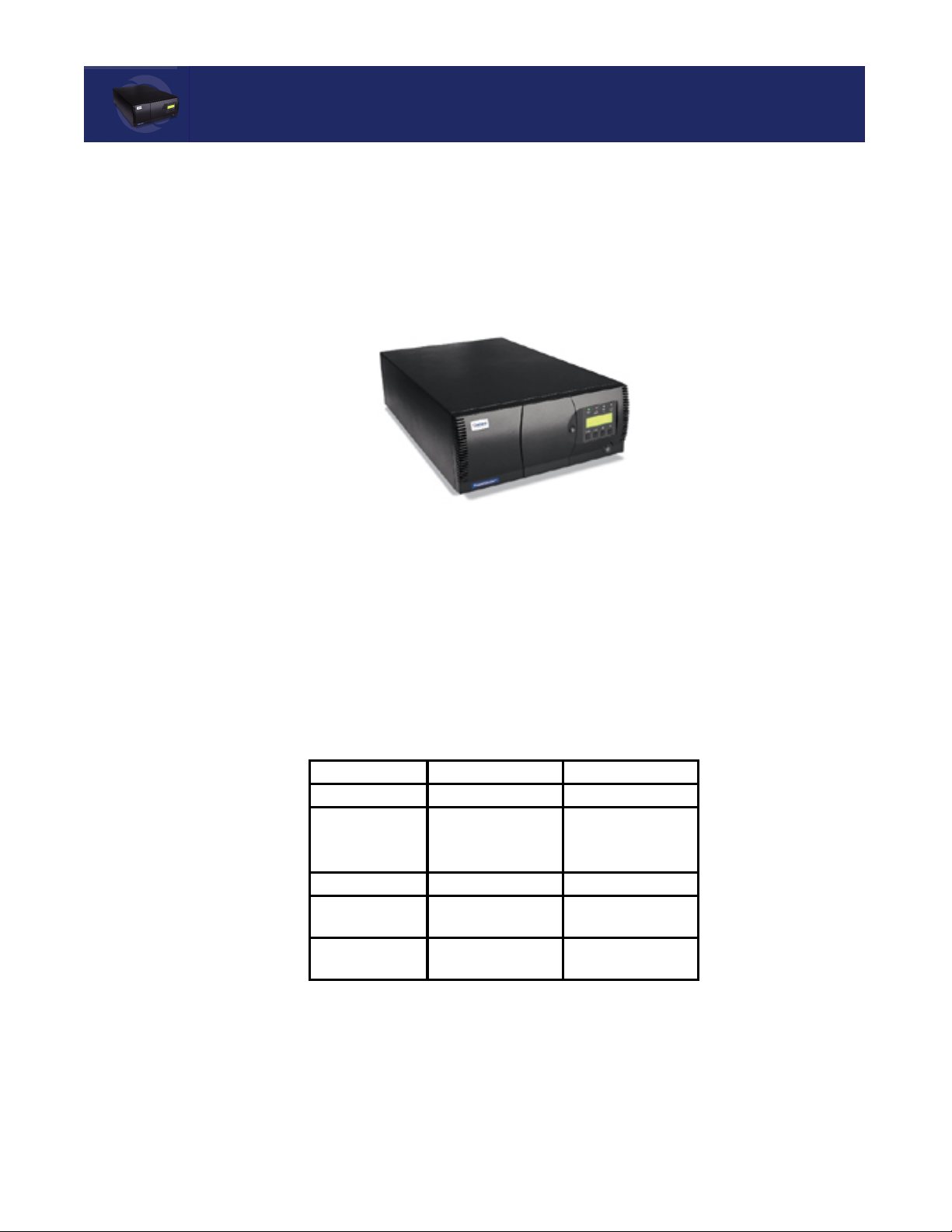
Your PowerLoader™ is a tape library system combining Advanced Intelligent Tape™ (AIT)
drive technology with advanced robotics. Designed for high duty-cycle online and near
online applications, such as hierarchical storage management, it is a superior performer in
high-volume backup and archival service.
Figure 1-1. PowerLoader
The PowerLoader™ can be equipped with one or two tape drives, and has a 19-slot tape
cartridge magazine, with a mail slot.
Models
PowerLoader™ features and model configurations are listed in Table 1- 1 and Table 1-2.
Table 1-1 PowerLoader™ Features
Component AIT-2 Tape Drive AIT-3 Tape Drive
Scalability From 1 to 9 modules From 1 to 9 modules
Media Slots 19 + 1 Mail Slot
Up to 171 + 9 Mail
Slots with 9 modules.
SCSI Interface HVD, LVD/SE LVD/SE
Number of Drives 1 or 2 Sony SDX-500
LVD AIT- 2 drives
Tape Cartridges
(8mm)
50 GB native 100 GB native
19 + 1 Mail Slot
Up to 171 + 9 Mail
Slots with 9 modules.
1 or 2 Sony SDX-700
LVD AIT-3 drives
Introduction t
1-1
Page 18

M
AIL SLOT
Mail Slot
Table 1-1 PowerLoader™ Features
Component AIT-2 Tape Drive AIT-3 Tape Drive
Mounting Tabletop (or
Rackmount with
conversion kit)
Table 1-2 PowerLoader™ Models
Model Number Configuration
AIT-LP2L119T/RB
AIT-LP2L219T/RB
AIT-LP3L119T/RB
AIT-LP3L219T/RB
1 Drive, AIT 2, Tabletop/Rackmount, LVD/SE SCSI
2 Drive, AIT 2, Tabletop/Rackmount, LVD/SE SCSI
1 Drive, AIT 3, Tabletop/Rackmount, LVD/SE SCSI
2 Drive, AIT 3, Tabletop/Rackmount, LVD/SE SCSI
Tabletop (or
Rackmount with
conversion kit)
If your host software permits, you can use the front slot in the magazine (the first slot you see
when you open the door) as a mail slot for inserting or removing a single cartridge without
interrupting host operations in progress. The mail slot is implemented using the SCSI
Import/Export commands.
SCSI Interface
The PowerLoader™ unit presents the following to the host:
•
A single SCSI medium changer device with a single SCSI Medium Transport element
•
A number of SCSI Storage elements equal to the total number of cartridge magazine
slots
•
A single SCSI Import/Export element
•
A number of SCSI Data Transfer elements equal to the total number of drives in the
system.
Multi-Server Data Sharing
A host computer with a SCSI controller connected to a bus is a SCSI Initiator. The
PowerLoader™ is a SCSI Target. SCSI rules permit multiple Initiators on a single bus.
Therefore, with the proper host software, it is possible to connect multiple hosts to a single
PowerLoader™ over a single SCSI bus. This allows multiple hosts to operate the library
robotics, loading and unloading cartridges as each host requires.
1-2
u Introduction
Page 19

SCSI BUS P
In a system with many drives, it may be desirable to use multiple SCSI buses for the drives so
the data transfer rate of the drives is not limited by bus bandwidth. Individual drives can be
connected to separate hosts. Using special software, one of the hosts can act as a master server,
processing all robotics commands and permitting several hosts to share a common database.
ERFORMANCE CONSIDERATIONS
Configurations
The PowerLoader™ standard SCSI interface is:
•
Fast/Wide Low Voltage Differential (LVD)/Single-Ended (S/E)
The PowerLoader™ uses high-density 68-pin D-series connectors. For more information see
SCSI Interfaces in Chapter 2.
SCSI Bus Performance Considerations
Drives
With a standard Fast/Wide SCSI interface, each drive offers a sustained native data transfer
rate of 6 MB/sec. (AIT-2) or 12 MB/sec. (AIT-3). In a two-drive module, the total native rate is
twice these rates. The rates for compressed data are the native rates multiplied by the
compression factor, which depends on file content, but averages approximately 2:1.
Data Transfer Rate
The data transfer rate of the PowerLoader™ depends on the type of AIT drive, the number of
drives, and on how many drives are connected to the SCSI bus. The robotics impose minimal
loading on the bus.
•
AIT-2 Ultra/Wide @ 40 MB/sec. (burst)
•
AIT-2 Sustained @ 6 MB/sec. (native) / 12 MB (compressed)
•
AIT-3 Ultra/Wide @ 80 MB/sec. (burst)
•
AIT-3 Sustained @ 12 MB/sec. (native) / 24 MB (compressed)
Each AIT-2 drive has a maximum sustained rate up to 12 MB/sec. with compressed data. Each
AIT-3 drive has a maximum sustained rate up to 24 MB/sec. with compressed data. As a result,
the transfer rate of a two-drive module occupies the full bandwidth of the bus. The maximum
performance of the system is degraded by sharing a SCSI bus among more than two drives.
Internal Cabling Configuration
Each SCSI bus in the PowerLoader™ System is wired separately. The library robotics and
Drive 1 share one bus; Drive 2 is connected to a separate SCSI bus. SCSI jumper cables are
available to allow the drives and robotics of a module to be daisy-chained to a single SCSI bus.
For more detailed information, see SCSI Interfaces in Chapter 2.
Introduction t 1-3
Page 20

SCSI BUS P
ERFORMANCE CONSIDERATIONS
Bus Length Limitations
If all devices and host adapter are LVD, length is 12 meters (1.5 meters in SE mode).
For customers using HVD, the high voltage differential Fast/Wide SCSI bus may be up
to 25 meters in length, including cabling within the modules.
Physical Configuration
PowerLoader™ comes configured as a tabletop or rack-mount model. The tabletop model can be
later converted for rack-mount usage. To convert a tabletop PowerLoader™ to a rack-mount
model, order the Overland Tabletop to Rackmount Conversion Kit (Part Number 106070-001).
Shuttle Lockdown Mechanism
Overland Data has installed a shuttle lockdown mechanism as a precautionary safety
mechanism to prevent damage to the PowerLoader™ during shipment from the factory. The
mechanism is a spring-loaded screw in the back of the PowerLoader™ that secures the shuttle
to a bracket.
You must release the shuttle lockdown mechanism before powering up the unit or it will
not operate. See the procedure in Chapter 2.
1-4
u Introduction
Page 21
SCSI BUS P
ERFORMANCE CONSIDERATIONS
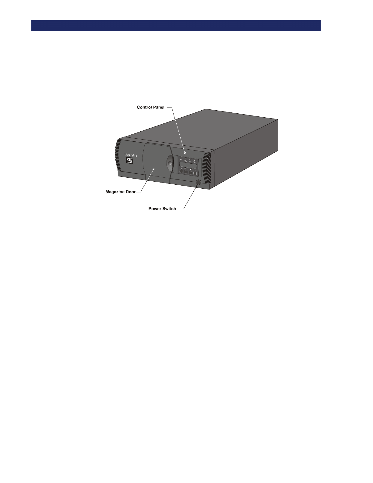
Features
This section describes and illustrates some of the external features of the PowerLoader™ by
Overland Data, Inc, including the control panel, power supply, tape cartridge magazine and
rear ports and connectors.
LP-0009
Figure 1–1. PowerLoader™ Front View
Control Panel
The control panel features a 4-line by 20-character backlit liquid crystal display, four LED
indicators and four buttons. The buttons enable the operator to navigate through the menu
structure to select and display operating modes, device status, diagnostic and maintenance
functions, device history and error statistics, and system configuration. The control panel is
described in detail in Chapter 3.
Display
The backlit 4-line by 20-character control panel display provides a highly intelligible
presentation of drive and loader status, menu choices and error messages. The scrolling feature
greatly expands the amount of information available to the operator.
Power Supply
The AC Power switch is located on the front panel of the module. The auto ranging power
supply adjusts automatically to either of two operating voltage ranges. The ranges are 100-120
VAC and 200-240 VAC. The power supply is capable of operating at 50 or 60 Hz without any
adjustment or modification. AC power is supplied to the power supply by a single IECcompatible socket, which can be connected to any properly grounded outlet.
Introduction t 1-5
Page 22
SCSI BUS P
ERFORMANCE CONSIDERATIONS
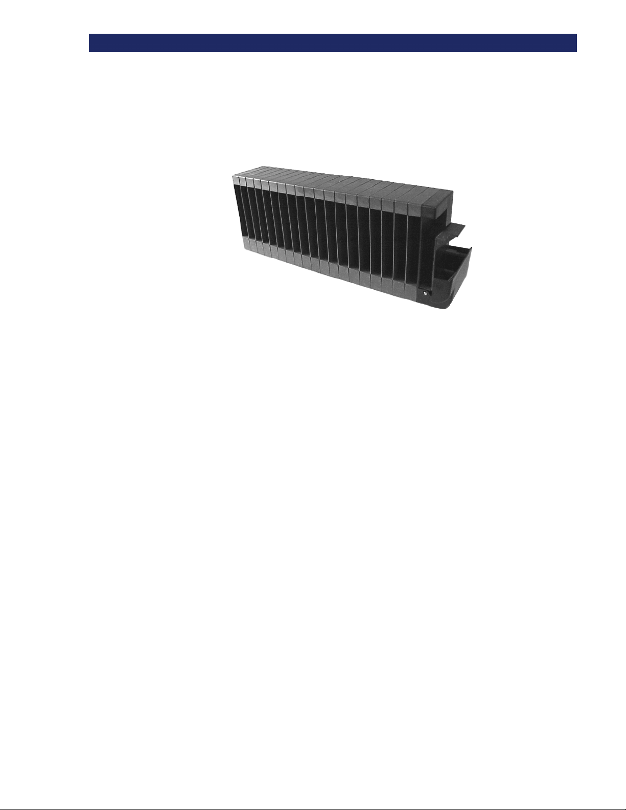
Tape Cartridge Magazine
The rugged polymer magazine, Figure 1–2 fits into an extruded track, which assures precise
positioning for the library robotics.
LP-0010
Figure 1–2. Cartridge Magazine
The front slot in the magazine is a Mail Slot, used to add or remove cartridges without
interrupting library operation. You can remove the magazine through the front door, but it is
protected from tampering in either of two ways:
•
An electronic combination lock, operated from the control panel
•
The host issuing a SCSI Prevent/Allow Medium Removal command.
For more information on inserting and removing the magazine, see Chapter 3.
Integral Fan Cooling
Each AIT drive contains a thermostat-controlled fan. In addition, a fan is mounted inside the
PowerLoader™ to prevent critical parts from overheating.
Robotics
The PowerLoader™ features Overland Data's Mainframe-Class™ Library Robotics. These
advanced robotics can load any of the cartridges stored in the magazine into any of the tape
drives.
Bar Code Reader
A standard barcode reader is mounted on the cartridge shuttle. It reads barcode labels attached
to each cartridge, and maintains the barcode data in memory as part of the library System Map.
1-6
u Introduction
Page 23

Advanced Design Features
Embedded Diagnostics
The PowerLoader™ provides three levels of embedded diagnostics:
1) Power-On Self Test (POST) - Performs various verification tests on the system's
configuration, host interface and device control functions, as well as memory tests when you
power on the unit.
2) User Diagnostics - Allow you to display and change configuration options. Select from front
panel.
3) CE Diagnostics - Advanced diagnostics used by Customer Engineers for servicing the
PowerLoader™. Select from front panel.
For more information on user diagnostics, see Chapter 2.
Error Checking
The drives used in the PowerLoader™ use read while write data checking and error-correction
code (ECC) technology such as is used in audio CD, DVD and laser discs.
A
DVANCED DESIGN FEATURES
Buffer
Drives are equipped with the following buffer size:
AIT-2: 10MB
AIT-3: 18 MB
Compression
The drives used in the PowerLoader™ use the Adaptive Lossless Data Compression (ALDC)
data compression algorithm developed by IBM.
Introduction t 1-7
Page 24

A
DVANCED DESIGN FEATURES
Capacity
The PowerLoader™, with its 19-cartridge magazine, offers formatted capacities as shown in
Table 1-3.
Table 1-3 Capacity
Model Native Capacity
per Cartridge
AIT-2 36 GB on
SDX236C media
50 GB on
SDX250C media
AIT-3 100 GB on
SDX3-100C media
Per Cartridge
Compressed
(2:1)
72 GB
100 GB
200 GB 3800 GB
Full Magazine
Compressed
(2:1)
1,368 GB
1,900 GB
Media Life
The media used in the PowerLoader™ is rated by the media manufacturer at over 30,000 endto-end passes, and a shelf life of at least 30 years.
.
1-8
u Introduction
Page 25

Chapter 2:
Chapter 2 Installation
This chapter describes installing the PowerLoader™ by Overland Data, Inc, including:
• Unpacking
• Releasing the Lockdown Mechanism
• Setting up the Desktop Model
• Setting up the Rackmount Model
• Setting up Cables and Interfaces
• Configuration
Unpacking
Installation
Follow the directions in the shipping container to unpack the PowerLoader™ and place it
in the desired physical location. Save the packing materials for reuse in case you need to
ship it.
Releasing the Lockdown Mechanism
Release the lockdown mechanism on the PowerLoader™, using the Lockdown Screw on
the back (lower right) of the unit, (Figure 2–1 and Figure 2–2).
Figure 2–1. Lockdown Screw
Installation t
2-1
Page 26

R
ELEASING THE LOCKDOWN MECHANISM
Lockdown
Screw
2-2
u Installation
Page 27

R
ELEASING THE LOCKDOWN MECHANISM
To Release the Lockdown Mechanism
You should release the Lockdown Mechanism before powering up the PowerLoader™.
1) Make sure that the power cord is disconnected from line power.
2) If necessary, reposition the unit for easier access to the back panel.
3) Turn the spring-loaded lockdown screw on the back counter-clockwise.
The screw pops out and the lockdown mechanism releases from the shuttle.
4) Turn the power on.
Tu rn
Lockdown
Screw
Countercloc
kwise to
release the
Figure 2–2. Releasing the Lockdown Screw
To Lock the Lockdown Mechanism
To lock the lockdown mechanism, do the following:
1) Park the shuttle assembly:
a. From the Main Menu, select Maintenance Menu / Park.
The shuttle assembly moves to the park position, bringing the threaded hole into
alignment with the lockdown screw.
2) Turn off the unit.
3) Disconnect the power cord from line power.
4) If necessary, reposition the unit for easier access to the back panel.
5) Push in the spring-loaded lockdown screw on the back and turn it clockwise.
This secures the shuttle to a bracket and locks it in place.
Installation t 2-3
Page 28

S
ETTING UP THE DESKTOP MODEL
Setting Up the Desktop Model
Tur n
Lockdown
Screw
Figure 2–3. Locking the Lockdown Screw
The PowerLoader™ desktop model requires no mechanical assembly for mounting. Place the
unit on a desk, table, server top, or other stable, horizontal surface. Make sure the cooling
grilles at the rear of the unit are not obstructed. Allow two inches of clearance behind the rear
panel.
Setting Up the Rack Mount Model
To convert a tabletop PowerLoader™ to a rack mount model, order the Overland Tabletop to
Rackmount Conversion Kit (Part Number 106070-001).
If your PowerLoader™ is already rack-mount configured, See “Installing Unit Into a Rack”.
Precaution
If you do mount the PowerLoader™ in a rack, be sure to take the following precaution:
CAUTION: TO PREVENT TIPPING, NEVER SLIDE MODULES OUT
OF THE RACK SO THAT MORE THAN 57 LB. OR 20% OF THE TOTAL
RACK WEIGHT IS EXTENDED AT ANY TIME
VORSICH: BITTE BEACHTEN, DAß WENN DIE LAUFWERSCHIENEN AUSGEZOGEN SIND, EINE
ZUSÄTZLICHE LAST VON MEHRALS 20% DES GESTALLGEWICHTES (225 KG), DIE STABILITÄT DES
GESTALLS GEFÄHRDED.
2-4
u Installation
Page 29
S
ETTING UP THE RACK MOUNT MODEL
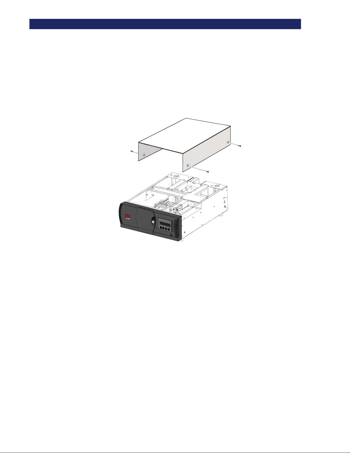
Remove Tabletop Cover
Before installing the tabletop PowerLoader™ module in a rack it must be converted for use,
using the Rack Mount Adapter Kit. First remove the tabletop cover Figure 2–4).
1) Remove the four screws (M4 x 8mm) that attach the cover to the sides of the unit.
2) Slide the cover toward the rear until clear of the unit.
3) Save the hardware for re-use.
R
e
a
d
y
U
s
e
C
l
e
a
n
e
r
D
i
r
v
e
F
a
u
L
o
l
t
a
d
e
r
F
a
u
l
t
E
s
c
p
a
e
n
E
te
r
LP-0005
Figure 2–4. Removing Desktop Cover
Installation t 2-5
Page 30
S
ETTING UP THE RACK MOUNT MODEL
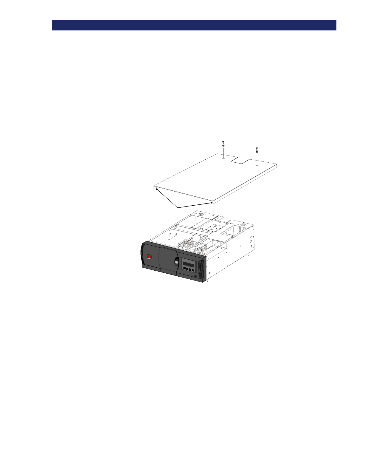
Install Top Cover
With the tabletop cover removed, install a sheet metal top cover that protects the
PowerLoader™ interior components when mounted in a rack (Figure 2–5).
1) Place the top cover over the PowerLoader™ chassis top with each side flange to the outside of
the chassis.
2) Slide the cover forward until it is flush with the front panel.
3) Fasten the cover with two screws (4M x 8mm).
4) Remove the four rubber feet on the bottom of the PowerLoader™.
Slide Flanges
Side Flanges
Figure 2–5. Installing the Top Cover
R
e
a
y
d
U
s
e
C
l
e
a
n
e
r
D
r
i
v
e
F
a
u
l
t
L
o
a
d
r
e
F
a
u
t
l
s
E
c
e
p
a
n
E
e
t
r
LP-0011
2-6
u Installation
Page 31

S
ETTING UP THE RACK MOUNT MODEL
Install The Rack Slides
After you've attached the top cover, attach rack slides to both sides of the module using the
procedure outlined below. Attach each inner slide of the rack slide assembly to the module
enclosure first. Fasten each outer slide to the rack mount cabinet later.
The left and right slides are alike, so there is no risk of confusing the parts on reassembly.
1) Figure 2–6 identifies the parts of the rack slide assembly.
Inner Slide
(attached to module)
Inner Slide Lock
Intermmediat e
Slide
Outer Slide
10-32 Screws
(Low Profile)
Lock Tab
Mounting
Bracket
LP-0013
10-32 Screws
Nut
Plates
Figure 2–6. Rack Slide Parts
2) Pull the outer slide toward the rear, along with the intermediate slide, until the inner slide lock
engages the intermediate slide.
3) Continue to pull the outer slide towards the rear until the outer slide lock engages the
intermediate slide. Press down on the inner slide lock to permit the intermediate slide to
continue to move toward the rear. Continue to move the outer and intermediate slides toward
the rear until they are separated from the inner slide. Push the intermediate slide back into the
outer slide.
4) Remove the inner slide of the second rack slide following steps 2-3.
5) Place an inner slide flat against one side of the module. Match screw holes in the slide to the
three screw holes on the module chassis. The inner slide lock must be toward the rear of the
module.
6) Use three M4x8mm screws to attach the inner slide to the side of the module as shown in
Figure 2–7.
Installation t 2-7
Page 32

S
ETTING UP THE RACK MOUNT MODEL
M4 x 8 Screws
(3 per side)
Inner Slide Lock
Figure 2–7. Attaching Rack Slides
LP-0012
7) Attach the second inner slide to the other side of the module.
Install the Panel Extensions
The left and right panel extensions are alike, so there is no risk of confusing the parts on
assembly.
1) Place a panel extension against one side of the chassis so that the holes in the panel extension
are aligned with the two holes in the chassis as shown in Figure 2–8.
Flush
Mount
Regular
Mount
2-8
u Installation
M4 x 8 Screws
(2 per side)
Figure 2–8. Panel Extension Attachment
LP-0016
2) Install two M4 X 8mm Phillips head screws through the holes in the panel extension into the
chassis.
The panel extension has two pairs of mounting holes. Use the forward pair for the regular
mounting position. Regular mounting leaves the curved front panel surface extending
outward from the front of the rack. The rear pair of holes permit a flush mount position
that leaves the front panel recessed into the rack. You might choose flush mounting if, for
example, you have rack doors that would be hindered by the protruding front panel.
Page 33

S
ETTING UP THE RACK MOUNT MODEL
3) Repeat steps 1 and 2 for the other side of the chassis.
Installing Unit Into a Rack
With the inner rack slides attached to the PowerLoader™ unit and the intermediate/outer
slides separated from the inner slides, you can install the outer rack slides in the rack.
1) Locate the screw holes in the front and rear rails of the cabinet or equipment rack where the
drive is to be installed.
2) Loosely assemble a mounting bracket to each outer slide, using two 10-32 screws and a nutplate for each. Select slots in the mounting brackets so the length of the assembly equals the
distance between the front and rear rails of the rack.
3) Fasten each outer slide behind the front rail of the rack using two 10-32 low-profile screws
and one nut plate.
4) Fasten each of the mounting brackets to the front of the rear rail of the rack using two standard
10-32 screws and one nut plate.
5) Tighten the screws installed in step 2.
6) If they are not already locked, pull the intermediate slides toward the front (out of the rack) so
that they lock in the extended position.
The next step should be performed by two people.
7) Install the Library unit into the rack:
h. In front of the rack, lift the module to its installed height.
i. Engage the inner slides mounted on the module with the intermediate slides protruding from the
rack
j. Slide the module toward the rack until the inner slide's lock engages the intermediate slides.
k. Depress the lock tab and continue until the lock tab engages in the locking hole shown in
Figure 2–9. This leaves the entire module protruding from the rack, locked in position, supported
by slides.
Locking Tab
Figure 2–9. Locking Tab
12)Press inward (toward the module) on each of the inner slide locks to permit the intermediate
slides to move toward the rack.
Installation t 2-9
Page 34

S
ETTING UP THE RACK MOUNT MODEL
13)Slide the module in and out several times as shown in Figure 2–10, ensuring that the inner and
outer slide locks engage, and that the module does not bind against the slides.
14)If binding or misalignment with other rack devices occurs, loosen the four screws that secure
the slides to the front rails and the four screws that secure the slides to the rear rails and
realign the module. Retighten the screws.
15)If necessary, repeat steps 9 and 10 until the module does not bind against the slides.
Figure 2–10. Sliding Module In Rack
16)Install two clip nuts on each front rail at the height of the front panel mounting screws
(thumbscrews).
17)Slide the module into the rack as shown in Figure 2–11, and tighten the thumbscrews.
2-10
u Installation
Page 35

S
ETTING UP THE RACK MOUNT MODEL
Figure 2–11. Module In Rack
You are now ready to connect power and interface cabling and configure the
PowerLoader™ module for use.
Installation t 2-11
Page 36

S
ETTING UP THE RACK MOUNT MODEL
Attach the AC Power Cord
1) Connect a standard grounding AC cord to the connector on the PowerLoader™. The
connector is an IEC-compatible connector on the rear panel.
2) Connect the other end to a reliably grounded AC outlet or rack power outlet.
To maintain safety compliance, use an approved power cord:
• U.S.UL Listed
• Canada CSA certified
• Europe Harmonized marked <HAR> or nationally certified
2-12
u Installation
Page 37

S
ETTING UP THE RACK MOUNT MODEL
Attaching Cables To SCSI Connectors
If your PowerLoader™ is used on a single-ended SCSI bus, the internal wiring length of
any rack-mounted SCSI system can approach the maximum length specification of a
single-ended SCSI bus. You must locate the rack close to the host computer to avoid
excessive bus length. It is also especially important in single-ended systems to use the
highest quality SCSI cables. Bus errors caused by excessive length or poor quality cables
can significantly degrade performance and reliability.
For those dual-drive applications where both AIT drives run in SCSI-SE mode (rather
than LVD mode), each drive must be connected to its own SCSI bus.
Each drive is wired to an independent bus, with a pair of SCSI connectors. Drive 1 shares a
SCSI bus with the PowerLoader™'s robotics. To fully use the bus bandwidth, connect all the
SCSI buses together as shown Figure 2–12. The insets in show how to connect the SCSI cable,
the jumper cables and the terminator for one or two-drive units.
SCSI
Terminator
SCSI
Host Cable
SCSI
Jumper Cable
AC Power Cord
Terminator
Expansion Ports
Terminator
Diagnostic
SCSI
Host
Cable
1 DRIVE
Motor
SCSI
Jumper
Cable
SCSI
Host
Cable
DRV 2
2 DRIVES
Figure 2–12. Connectors, SCSI Terminator & Cables
Each of the drives in the PowerLoader™ and the robotics is a separate SCSI device. When any
two or more devices are connected to the same SCSI bus, each separate SCSI device must be
assigned a unique SCSI address. For information on assigning SCSI addresses, see the
Configuration section later in this chapter.
Installation t 2-13
Page 38

S
ETTING UP THE RACK MOUNT MODEL
To connect a PowerLoader™ to a host computer, the host must have at least one Wide SCSI
controller and the appropriate driver software. The controller must be LVD/SE or differential,
as required to match the module interface.
Interface Cable Specifications
PowerLoader™ is a high-performance system. To avoid degradation of performance, use the
•
highest-quality interface cables from a reputable manufacturer of computer cables. All SCSI
cables used with the PowerLoader™ should meet the following requirements:
• Shielded or double-shielded, as required to meet EMI specifications
• Impedance match with cable terminators that meet current SCSI specifications
• Characteristic impedance between 72 and 96 ohms for single-ended and between 115 and 160
ohms for differential
• 34-pair twisted-pair
• Each end of a twisted pair ground connected to chassis ground
• Maximum cable length of 5 feet (1.5 m) for the LVD/SE model in single-ended mode
connected to a host SCSI adapter capable of Ultra SCSI speed
• Maximum cable length of 40 feet (12 m) for LVD/SE SCSI bus
• Internal cable lengths of 22 inches for Drive 1 and Robot and 15 inches for Drive 2
• Cables of different impedances should not be used together.
Additional specifications to assure the highest SCSI performance can be found in the current
version of ANSI X3.131.
This equipment has been tested for electromagnetic emissions and immunity using good
quality shielded cables. If you use unshielded or poor quality cables, or otherwise vary
from good practice, you may not comply with national and international rules.
Configuring the PowerLoader™
The PowerLoader™ is designed with many configuration options, each offering multiple
settings to support a variety of applications and platforms. The setting of each option is stored
in non-volatile memory in the module. For most applications, you do not have to change the
factory default settings. If you need to change the configuration, go on to the next section. If you
are uncertain whether you need to change a setting, contact your Technical Support
representative.
To change settings, use the Control Panel. For an overview of how the Control Panel works, and
a description of the functions of the buttons, indicators and display, refer to Entering the Menu
Mode, Exiting the Menu Mode, and Navigating through the Menu Structure in Chapter 3.
2-14
u Installation
You can change the settings using the procedure in How to Customize Configuration later in
this chapter. Consult your host computer and software documentation to determine which
settings you might have to change.
Page 39

S
ETTING UP THE RACK MOUNT MODEL
Configuration Example: Setting the SCSI ID
1) Turn the PowerLoader™ on and wait until the Power-On Self Test terminates and the default
screen displays. You can toggle between the Primary and Secondary Default Screens with the
p and q buttons.
Loader Idle
Drv 1: No
Drv 2:
Figure 2–13. Primary Default Screen
Ready
1
uuuu
_ _ _ _ _ _ _ _ _
11
uuuu
_ _ _ _ _ _ _
Figure 2–14. Secondary Default Screen
tttt
10
tttt
19
Installation t 2-15
Page 40

S
ETTING UP THE RACK MOUNT MODEL
2) At the Default Screen, press the Enter button. The screen displays the Main Menu:
3) Press the q button three times to scroll to the Configure Menu, and press Enter. The screen
displays the Configure submenu:
4) To select a configuration option, press the p or q button on the control panel until the u
displays next to the option you want to change. The first two choices on this menu, SCSI
Options and Library Options, are actually categories of options. In this case, choose SCSI
Options. Press the Enter button to display the options for that category. The submenu displays:
uuuu
Load/Unload
Remove
Maintenance
Configure
Figure 2–15. Main Menu
uuuu
SCSI Options
Library
Barcode
Set Base
Figure 2–16. Configure Submenu
$
#
u
Library
✴✴✴✴
Enabled
Library Bus ID:
✴✴✴✴
6
Figure 2–17. SCSI Options Submenu
$
Take a moment to look closely at the submenu. Note that the u on the display is next to
line 1, and that line 2 is indented, indicating a two-tiered menu. The p and q buttons
work on two levels in this kind of menu, which is typical of many submenus of the
Configure Menu. The first level is as follows: If you press the q button, the u moves to
line 3. If you press the p button, the u moves back to line 1.
If you press the
on the second level. You can tell because the
at the end of line 4, indicating that there is a list of settings that can be scrolled using the
q
buttons.
The
$$$$
at the end of line 4 means that there are other options that can be displayed by scrolling,
using the
Enter
button while the u is next to line 1 (or line 3), the
q
button repeatedly.
p
and
q
buttons operate
u
moves next to line 2 (or line 4), and a ✴ displays
p
and
2-16
u Installation
Page 41

C
ONFIGURING MULTI-MODULE SYSTEMS
5) Suppose you want to set the Drive 1 bus ID to 3. With the u next to line 1, press the q button
until the display scrolls as shown in the following screen:
u Library Bus
✴✴✴✴
6
#
Drive 1 Bus ID:
✴✴✴✴
4
Figure 2–18. SCSI Options Submenu
6) With the u next to line 3, press the Enter button. The u moves to line 4 and the $
the end of line 4, and a
to display the possible settings. Scroll up so that 3 is displayed and press the
save the new selection. An
7) Press the
8) Repeat this procedure for each configuration option you want to change.
Escape button repeatedly until the submenu reappears.
#### displays at the end of line 1. Use the p and q buttons to scroll line 4
✴✴✴✴ displays to the left of the 3 indicating it as the current selection.
$ remains at
$$
Enter button to
Configuring Multi-Module Systems
All PowerLoader™ modules are factory-shipped as stand-alone units meant to operate as
individuals. To include them in a multi-module system, you must first configure one
module as the master module and all other modules as slave modules. PowerLoader™
module can be configured to be a stand-alone, master, or slave module.
Master Module
The master module controls the operations of the multi-module system. Configuration
changes to the system are performed at the operator panel of the master module.
In a rack, the master module must occupy the top position to coordinate the action of the
Pass-Through Mechanism
Configuring The Master Module:
1) From the Default Screen, press Enter to display the main menu.
.
uuuu
Load/Unload
Remove
Maintenance
Configure
Figure 2–19. Main Menu
2) Press the q button three times to move the u to Configure Menu, then press the Enter button.
The screen displays the Configure submenu:
$
Installation t 2-17
Page 42

C
ONFIGURING MULTI-MODULE SYSTEMS
3) Press the q button to move the u to Library Options, then press the Enter button. The
following screen appears:
4) Press Enter to move the cursor to the second line.
uuuu
SCSI Options
#
Library
Barcode
Set Base
Figure 2–20. Configure Submenu
uuuu
Configuration
✴✴✴✴
Standalone
Unload Mode
✴✴✴✴
Implicit
Figure 2–21. Library Options Menu
$
5) Use the q and p buttons to change the option to
6) Press
Enter to save the selection.
Master.
The change takes effect when you reboot.
Slave Module
You can configure the slave module on the bench before installation or after it is installed
in a rack. If you configure it when it is already installed as part of a multi-module system,
be sure to either shut off power to the master module or disconnect the serial cables. This
precaution will let you access menu mode directly, avoiding interfering communication
from the master module.
Each slave module must have a unique one digit ID that you specify as part of the
configuration procedure. You must stack and number the units as follows:
Table 2-1 Stack and Unit Numbering Example
Master
Slave 0
Slave 1
Slave 2
2-18
u Installation
Slave 3
Configuring The Slave Module
1) From the Default Screen, press Enter to display the main menu.
Page 43

C
ONFIGURING MULTI-MODULE SYSTEMS
uuuu
Load/Unload
Remove
Maintenance
Configure
Figure 2–22. Main Menu
2) Press the q button three times to move the u to Configure Menu, then press the Enter button.
The screen displays the Configure submenu:
uuuu
SCSI Options
$
#
Library
Barcode
Set Base
Figure 2–23. Configure Submenu
3) Press the q button to move the u to Library Options, then press the Enter button. The
following screen appears:
uuuu
Configuration
✴✴✴✴
Standalone
Unload Mode
✴✴✴✴
Implicit
$
Figure 2–24. Library Options Submenu
Installation t 2-19
Page 44

S
ETTING UP RESERVED SLOTS
4) Press Enter to move the cursor to the second line.
5) Use the q and p buttons to change the option to
6) Press
Enter to save the selection. The display at lines 3 and 4 changes to allow specification of
a numerical ID for the slave module.
You must reboot to display the Slave Module ID.
uuuu
Configuration
✴✴✴✴
Slave
Slave Address
✴✴✴✴
0
Figure 2–25. Library Options Submenu (Slave Address)
7) Press the q button to move the move the u to Slave Address.
8) Press
9) Use the q and p buttons to change the number.
10)Press
Enter to move the cursor to the number option on the fourth line.
Enter to save the selection.
The configuration change takes affect when you reboot.
Setting Up Reserved Slots
Slave.
$
Use this option to withdraw some of the slots in the PowerLoader™ from use as storage slots to
meet software licensing requirements or to dedicate one or more slots as a cleaning slot.
Reserved Slot Numbering
Ordinary cartridge slots are numbered from the front of the magazine to the rear. If you reserve
one slot, it becomes Reserved Slot #1 in the last slot (#19) of the magazine. If you reserve two
slots, slot #18 becomes Reserved Slot # 1, while slot #19 becomes Reserved Slot #2. Additional
reserved slots continue in this rear-to-front pattern. Reserved Slot #1 always follows the last
unreserved data cartridge, see Figure 2–26.
2-20
u Installation
Page 45

S
ETTING UP RESERVED SLOTS
If you reserve one slot
Reserved Slot #1 g
g
gg
#19
#18
#17
#16
#15
#14
#13
#12
#10
#9
#8
#7
#6
#5
#4
#3
#2
#1
Front
Figure 2–26. Reserved Slot Numbering
Reserving Slots
1) From the Default Screen, press Enter to display the main menu.
If you reserve two slots
f
f Reserved Slot #2
ff
ffff Reserved Slot #1
uuuu
Load/Unload
Remove
Maintenance
Configure
Figure 2–27. Main Menu
$
Installation t 2-21
Page 46

C
ONFIGURATION OPTIONS DESCRIPTION
2) Press the q button three times to move the u to Configure Menu, then press the Enter button.
The screen displays the Configure submenu:
3) Scroll down by pressing the q button to move the u to Library Options, then press the Enter
button. The following screen appears:
4) Scroll down to Reserved Slots by pressing the q button and press Enter. The Reserved Slots
Submenu displays:
uuuu
SCSI Options
#
Library
Barcode
Set Base
Figure 2–28. Configure Submenu
uuuu
Configuration
✴✴✴✴
Standalone
Unload Mode:
✴✴✴✴
Implicit
Figure 2–29. Library Options Submenu
$
Baud Rate:
✴✴✴✴
38,400
Reserved Slots
✴✴✴✴
0
Figure 2–30. Reserved Slots Submenu
5) Scroll down to line 4 and specify the number of slots you are reserving. Press Enter to save.
$
If your software license limits the number of usable slots in the magazine, you must
reserve the remaining slots. You can use any of the reserved slots to store a cleaning tape.
(see Chapter 4 - Maintenance).
6) Press the Escape button repeatedly to return to the Default Screen. Your choice takes effect the
next time the PowerLoader™ is rebooted.
Configuration Options Description
The following options are available on the Configuration Menu:
SCSI Options
Library Parity:
The default is Library Parity Enabled.
Allows you to enable or disable the library robotics SCSI bus parity checking.
2-22
u Installation
Library Bus ID:
Allows you to set the SCSI addresses of the library robotics. The default is 6.
Page 47

C
ONFIGURATION OPTIONS DESCRIPTION
Drive n Bus ID:
Allows you to set the SCSI addresses of the drives. The designators Drive 1
through Drive n refer to the first through nth drives, counting from the top module in the
PowerLoader™.
Vend or ID :
Allows you to specify the response of the LibraryPro™'s robotics to the SCSI
Inquiry command in the Vendor ID field. The default is OVERLAND.
Product ID:
Allows you to specify the response of the LibraryPro™'s robotics to the SCSI
Inquiry command in the Product ID fields (LIBRARYPRO, LXB, EXB-210, EXB-440, EXB-480,
SSL2000 Series C, <Vendor unique>. The default is LIBRARYPRO.
Negotiation Mode:
Allows you to enable Initiate Synchronous Negotiation. Initiate
Synchronous Negotiation, if set, allows the LibraryPro™ to initiate SCSI Synchronous
Negotiation with the host (the default is No). The LibraryPro™ always responds to hostinitiated synchronous negotiation.
Transfer Rate:
Allows you to set the data Transfer Rate to 10 MB/sec, 5 MB/sec or
Asynchronous. The default is 10 MB/sec.
Mode Page 1F Length:
Allows you to choose between two lengths of the Mode Sense/Select
Device Capabilities Page (SCSI Page 1Fh), which are Short (14 bytes) and Long (18 bytes), to
accommodate different SCSI device implementations of this page. The default is Short.
Abort Move Status:
Enables you to specify the module’s response if it receives a SCSI Reset or
Abort while a Move Medium command is in progress. Depending on this setting, during
execution of the Move Medium command, the module will return either Busy or Not ready in
response to the SCSI Reset or Abort. The default is Busy.
Initialize Element Status:
Allows you to specify the module's response to the SCSI Initialize
Element Status command. The possible settings are No Inventory, Force Inventory, and Force
Label Scan. The default is No Inventory.
Unit Attn Report:
Allows you to select reporting of All or only One unit attention conditions. If
set to All, the unit reports all unit attention conditions in sequence; if set to One, the unit
reports only the highest priority condition. The default is All.
SCSI Mode:
Post Recv'd Error:
Defines the loader as SCSI-2 or SCSI-3. The default is SCSI-2.
Enables reporting of TapeAlert informational exception conditions with a
Recovered Error sense key, when the Method of Reporting Information Exceptions (MRIE) field
is set to a value of 0x3 in Mode Page 1Ch, or if the TapeAlert Mode option is set to Rec Error
(cnd). The default is Disabled.
Tape Alert Mode:
Specifies conditions for logging and reporting TapeAlert data. The default
is Logging Disabled.
• Logging Disabled-Inhibits logging feature.
• No Exceptions-Device should not report information exceptions.
• Unit Attention-Report information exceptions with a Unit Attention sense key and an
ASC/ASCQ of 5D/00.
• Rec Error (cnd)-Report information exceptions with a Recovered Error sense key and an
ASC/ASCQ of 5D/00, if Recovered Error Reporting is enabled.
Installation t 2-23
Page 48

C
ONFIGURATION OPTIONS DESCRIPTION
• Rec Error (unc)-Unconditionally report information exceptions with a Recovered Error sense
key and an ASC/ASCQ of 5D/00.
• No Sense-Report information exceptions with a No Sense sense key and an ASC/ASCQ of
5D/00.
• On Request- Report information exceptions with a No Sense sense key and an ASC/ASCQ of
5D/00, only in response to an unsolicited Request Sense command.
Library Options
Configuration:
or slave module. The default is stand-alone. Do not select the “Master” or “Slave” options.
Unload Mode:
interpreted as Implicit or Explicit. If Implicit, the module unloads a drive before attempting to
move a cartridge from that drive. If Explicit, the host must issue a SCSI Unload command to a
drive before each Move Medium command that removes a cartridge from that drive. The default
is Implicit.
Numbering:
or one. This affects only the front panel display, not the actual SCSI element addresses. The
default is One.
Auto Clean:
cartridge unload sequence whenever the Use Cleaner LED comes on. To use this option, you
must have reserved a slot for a cleaning cartridge using the Reserve Slots option. The default is
Disabled.
Library Mode:
Sequential 2 or Sequential Split. The default is Random.
The menu allows you to configure the LibraryPro™ as a stand-alone, master,
Allows you to determine whether a SCSI Move Medium command is
Allows you to specify whether SCSI elements in the unit display with either zero
Allows you to enable an automatic cleaning cycle which operates as part of the
Allows you to set the robotics operating mode to Random, Sequential 1,
The sequential operating modes are available in standalone configuration only. If only
one drive is installed, only the Sequential 1 option is available.
Random
Sequential 1
-Normal operating mode. Allows complete host control of the robotics.
-Loads cartridges in numerical order in all 19 magazine slots for Drive 1.
2-24
u Installation
Sequential 2
Sequential Split
- Loads cartridges in numerical order in all 19 magazine slots for Drive 2.
-Loads cartridges in numerical order in magazine slots 1 through 10 for
Drive 1 and magazine slots 11 through 19 for Drive 2.
Baud Rate:
intended for use by CEs only. The default is 38400 bits/sec.
Reserved Slots:
magazine. Some host software imposes size limits on tape library magazines for licensing
purposes, and does not operate with a library that exceeds the licensed size. The default is 0.
Model Number:
screens. You can choose between LIBRARYPRO, a blank line, CompaqSSL2020, and a vendor
unique number. The Default is LIBRARYPRO.
Allows you to set the data transmission rate of the trace port. This function is
Allows you to withdraw from use a specified number of slots in the back of the
Allows you to change the model number information displayed on the initial
Page 49

Barcode Options
C
ONFIGURATION OPTIONS DESCRIPTION
Label Size:
Allows you to limit length of the barcode label. Possible settings are 1 through 8.
The default is 8.
Label Alignment:
Allows you to specify alignment of barcode label. The options are Left or
Right. When used with the label size option, strips unwanted trailing characters (left
alignment) or leading characters (right alignment). The default is Left Alignment.
Check Digit:
Allows you to enable or disable check digit function. For barcodes without check
digits, you can select Disable. For barcodes with check digits, you can select Enable/Send or
Enable/No Send. The default is Disable.
Set Element Base
Transport:
Storage:
Transfer:
Import/Export:
Allows you to set the base address of the robotics mechanism. The default is 0000.
Allows you to set the base address of the 19 magazine slots. The default is 0001.
Allows you to set the base address of the drive. The default is 00E0 for Drive 1.
Allows you to set the base address of the mail slot. The default is 00D0.
Set Serial Number
Serial Number:
PowerLoader™'s robotics reports these settings in response to the SCSI Inquiry command in
the Unit Serial Number Page.
Allows you to alter the module's serial number as stored in the unit. The
Set Default
Overland Defaults:
The default is Overland defaults.
The following tables summarizes the configuration settings for the PowerLoader™.
Resets all configuration options to Overland defaults or Compaq defaults.
Table 2-1 PowerLoader™ SCSI Options
Option Setting Default
Library Parity Enabled, Disabled Enabled
Library ID SCSI ID 0-15 6
Drive or Bus ID SCSI ID 0-15
Vender ID OVERLAND,
EXABYTE, Compaq,
<VENDOR
UNIQUE>
OVERLAND
Installation t 2-25
Page 50

C
ONFIGURATION OPTIONS DESCRIPTION
Table 2-1 PowerLoader™ SCSI Options
Option Setting Default
Product ID LIBRARYPRO, LXB,
EXB-210, EXB-440,
EXB-480, SSL2000
Series, <Vendor
Unique>
Negotiation Mode Initiate, Do Not
Initiate
Transfer Rage Sync 5 MB/sec, Sync
10 MB/sec, Async
only
Mode Page 1F Length Short (000E), Long
(0012)
Abort Move Status Busy, Not Ready Busy
Init. Element Status No Inventory, Force
Inventory, Force
Label Scan
Unit Attention Report One, All All
SCSI Mode SCSI-2, SCSI-3 SCSI-2
Post Recv'd Error Enabled, Disabled Disabled
Tape Alert Mode Logging Disabled, No
Exceptions, Unit
Attention, Rec Error
(cnd), Rec Error
(unc), No Sense, On
Request
LIBRARYPR
O
Do Not
Initiate
Sync 10
MB/sec
Short
No Inventory
Logging
Disabled
2-26
u Installation
Table 2-2 PowerLoader Library Options
Option Setting Default
Configuration Standalone, Master,
Slave
Unload Mode Implicit, Explicit Implicit
Numbering One Based, Zero
Based
Auto Clean Enabled, Disabled Disabled
Library Mode Random, Sequential
1, Sequential 2,
Sequential Split
Baud Rate Auto, 2400, 9600,
19200, 38400, 57600,
115200
Reserved Slots 0 through n (one less
than magazine)
Standalone
One Based
Random
38400
0
Page 51

C
ONFIGURATION OPTIONS DESCRIPTION
Table 2-2 PowerLoader Library Options
Option Setting Default
Model Number LIBRARYPRO,
<Blank Line>,
Compaq SSL2020,
<Vendor Unique>
OVERLAND
LIBRARYPR
O
Table 2-3 PowerLoader Barcode Options
Option Setting Default
Label Size 1 through 8 8
Label Alignment Left or Right Left
Check Digit Disable for barcodes
w/o check digits,
Enable/Send or
Enable/No Send for
barcodes with check
digits
Enable/No
Send
Table 2-4 PowerLoader Set Element Base Options
Option Setting Default
Transport NNNN (hex) 0000
Storage NNNN (hex) 0001
Transfer NNNN (hex) 00E0
Import/Export NNNN (hex) 00D0
Table 2-5 PowerLoader Set Serial Number Option
Option Setting Default
Serial Number NXNNNNNNNN
(hex)
9F99999999
Table 2-6 PowerLoader Set Default Option
Option Setting Default
Overland Defaults Overland Defaults,
Compaq Defaults
Overland
Defaults
The options described in this table represent the version of the firmware in use when this
manual was written. If the options displayed on your control panel differ from those
described here, you can download the latest option descriptions from the Overland Data
web site (www.Overlanddata.com) or contact your Technical Support representative.
Installation t 2-27
Page 52

C
ONFIGURATION OPTIONS DESCRIPTION
2-28
u Installation
Page 53

Chapter 3:
Chapter 3 Operation
Operation
This chapter describes operating the
of the unit.
PowerLoader™
through the Control Panel on the front
Front Panel
The front panel of the PowerLoader™ module includes a power switch for the module and
the control panel, which has buttons, a display and indicators.
LP-0009
Figure 3–1. PowerLoader™ Front Panel
Power Switch
The power switch controls the supply of AC power to the PowerLoader™. It is a push-on,
push-off switch. When the power is on, the backplane of the control panel display is
illuminated.
Buttons and Indicators
The control panel consists of four LED indicators, a four-line by 20-character backlit LCD
display, and four buttons.
Operation t
3-1
Page 54

F
RONT PANEL
Ready
(Green)
Escape
Use Cleaner
(Yellow)
Enter
Drive Fault
(Red)
Scroll Up
Loader Fault
Scroll Down
(Red)
Display Panel
Figure 3–2. Buttons & Indicators
Buttons
There are four buttons on the control panel:
control specific functions or options. Instead, you use the buttons to navigate from the Default
Screen through a multi-level menu structure, then select the desired option from the
Enter
appropriate menu using the
button.
Escape, Enter
, p, and q. The buttons do not directly
Using the
Enter
button to access the Main Menu
To enter the Menu Mode and display the Main Menu from the Default Screen, press the Enter
button. When you enter the Menu Mode, the
Ready
light goes out. This means that the
PowerLoader™ is offline, and the PowerLoader™ responds to all commands from the host with
Ready
a SCSI Not Ready until you exit the Menu Mode and the
light goes on.
Escape Button - Return To Default Screen
To return to the Main Menu from a submenu, press the
Escape
Menu displays. Pressing the
button while the Main Menu is displayed exits the Menu
Mode and returns you to the Default Screen.
Escape
button repeatedly until the Main
Escape Button - Access Status Mode
To enter the Status Mode, which displays all aspects of the PowerLoader™'s operating and
Escape
configuration status, press the
remains online.
button at the Default Screen. The PowerLoader™
3-2
u Operation
Page 55

LED Indicators
F
RONT PANEL
There are four LED indicators on the control panel, labeled
Drive Fault
The
(red), and
Ready
LED (green) is illuminated when the PowerLoader™ is ready to accept commands
Loader Fault
(red).
Ready
(green),
Use Cleaner
(yellow),
from the host computer. The Ready indicator goes out when you enter the Menu Mode,
indicating that the PowerLoader™ is offline.
The
Use Cleaner
LED (yellow) indicates that one or more of the drives in the PowerLoader™
needs cleaning. Perform a cleaning operation as described in Chapter 4 - Maintenance. When
Use Cleaner
the
comes on, you can find out which drive needs cleaning by selecting Cleaning
Needed on the Drive Status submenu.
When either the
Drive Fault
or the
Loader Fault
LED (red) is illuminated, a Fault Screen displays
on the LCD display. The Fault Screen is described later in this chapter.
See Chapter 5 - Troubleshooting for a list of fault symptom codes (FSC) and error recovery
procedures (ERP).
Operation t 3-3
Page 56

F
RONT PANEL
Table 3-1 Control Panel Button Functions
Display/Mode Escape Enter ppppq
At Post Screen N/A N/A N/A
At Default Screen Enters Status
Mode
In Status Mode
(while online)
In Menu Mode Rejects Currently
At Fault Screen N/A Clears Soft Errors N/A N/A
Returns to Default
Screen
Displayed Choice,
or
Aborts Control
Panel Operation In
Progress, or
Exits to Next
Higher Menu
Level, or
Exits Menu Mode
to Default Screen
Enters Menu Mode Toggles
between
Page 1
and Page 2
Same as Menu
Mode
Accepts Currently
Displayed Choice
Same as
Menu Mode
Moves
Line Upward
Through List
of Options, or
Scrolls Part
of Display 1
Line Toward
Top of List of
Options
u 1
q
qq
N/A
Toggles
between
Page 1
and Page 2
Same as
Menu Mode
Moves
u 1
Line
Downward
Through List
of Options, or
Scrolls Part
of Display 1
Line Toward
Bottom of
List of
Options
There is an auto-repeat feature for the
pppp
and
qqqq
buttons. When you press either button
for more than one-half second, the control panel behaves as if you were pressing and
releasing the button about four times per second. This effect stops when you release the
button.
Front Panel & Media Locks
To avoid accidental interruption of PowerLoader™ operation by entering the Menu Mode or
removing cartridges while the host is accessing the PowerLoader™, the front panel and the
media may be electronically locked. When the front panel is locked, you can only enter the
Menu Mode after entering a 4-digit code. That is, when the Default Screen is displayed,
pressing the
panel cannot be unlocked without using the Security submenu to unlock it.
The media may also be locked by software running on the host, using the SCSI Prevent/Allow
Medium Removal command. The PowerLoader™ provides no control panel override for this
command. Usually, exiting the host software restores media access. In the event of host failure,
you can restore media access by cycling PowerLoader™ power.
Procedures for locking and unlocking front panels and media are described later in this chapter.
Enter
button does not invoke the Menu Mode until you enter the code. The front
3-4
u Operation
Page 57

F
RONT PANEL
Startup Display Messages
The display on the control panel is capable of displaying four lines of 20 characters each, to
allow the use of easy-to-understand messages. Many of these messages and their functions are
described in this chapter. Those displays that are described in other chapters are crossreferenced here as well.
Power-On Self Test Screen
When power is first applied to the module, a series of power-on self test (POST) diagnostics are
performed. During POST execution, the model number of the module, the firmware revision,
and the status or result of the test in progress are displayed on the control panel.
Power-On Self Test (POST) Screen
When power is first applied to the module, a series of power-on self test (POST) diagnostics are
performed. During POST execution, the model number of the module, the firmware revision,
and the status or result of the test in progress are displayed on the control panel.
OVERLAND LIBRARYPRO
Firmware Level
Checking Hardware
0X.XX
Figure 3–3. POST Screen
Operation t 3-5
Page 58

F
RONT PANEL
Initialization Screens
After the POST is completed, the library robotics are initialized. A series of screens similar to
the following displayed during this process.
OVERLAND LIBRARYPRO
Firmware Level
0X.XX
Initializing Loader
Figure 3–4. Initialization Screen
Default Screen
After the POST diagnostics have concluded successfully and initialization is complete, the
default screen displays, as shown in the following example. The Default Screen consists of two
pages.
Loader Idle
Drv 1: No Tape
Drv 2: No Tape
Page 1
Press the q
q and pppp
qq
buttons to toggle
between the two
pages.
Loader Idle
1
uuuu
_ _ _ _ _ _ _ _ _
11 u
u _ _ _ _ _ _ _ tttt19
uu
tttt
10
tttt
Page 2
Figure 3–5. Default Screens
Page 1 displays library and drive status. Page 2 displays library status (Line 1) and magazine
slot status (Lines 3 and 4).
The library status lines show each slot as a rectangle. A solid block indicated that a cartridge is
present. An underline indicates that a slot is empty.
Line 4 also shows the status of the mail slot:
tttt indicates that a cartridge is in the mail slot.
vvvv indicates that the mail slot is empty
3-6
u Operation
Page 59

F
RONT PANEL
Fault Screen
When a fault is detected, a screen similar to the following displays.
(In addition, either the Drive Fault or the Loader Fault LED on the control panel lights up.)
Fault Code:
3005
Picker Jammed
Power Down to Clear
Figure 3–6. Fault Screen
The first line of the Fault Screen displays a numerical fault symptom code (FSC). The second
line displays a brief description of the error. The third and fourth lines display a one- or two-line
message describing the initial error recovery procedure (ERP).
For a list of the fault symptom codes (FSC) and error recovery procedures (ERP) see Chapter 5 -
Troubleshooting.
Operation t 3-7
Page 60

U
SING POWERLOADER
Using PowerLoader™ Menus
Use the PowerLoader™ menus (shown in the following illustration) to display status
information and to operate and configure the PowerLoader™.
™ M
ENUS
Power-Up Displays
Show Status Menu
Access Mail Slot
Library Status
Model Number
Firmware Revision
SCSI Bus ID
SCSI Bus Parity
Boot Version
Flash Type
Library Mode
Library Config
Vendor ID
Product ID
Baud Rate
Transport A ddr
Storage A ddr
Transf er Addr
Import/Export*
Serial Number
Negotiation Mode
Transfer Rate
Unload Mode
Auto Clean Mode
Reserved Slots
Mode Page 1 f Length
TUR Reporting
Init Elem Status
Barcode Reader
Label Size
Label Alignment
Loader Status
Abort Move Status
SCSI Mode
Post Recev'd Error
Tape Alert Error
Escape Button
Load/Unload Remove Magazine
From/To
Drive n Status
Tape Motion
SCSI Bus ID
Drive Type
Firmware Revision
Serial Number
IEEE Global ID
Cartridge Present
Cleaning Needed
Write Protected
Cartridge Status
Tape Load Count
Tape Remaining
Map In fo
*Displays if Mail Slot enabled
Maintenance Menu
Clean Drive
Cleaning
Using
Diagnostics
Cartridge Cycle
Friction Test
Tach Feedback
Scanner Feedback
Scan Labels
Demo Menu
Demo
1
Demo 2
Flash Update
NOVRAM U pdate
Park
Reboot M odule
Default D isplay
Panel Lo ck
Main Menu
Enter Button
Configuration Menu
SCSI Options
Library Parity
Library Bus ID
Drive n Bus ID
Vendor ID
Product ID
Negotiation Mode
Transfer Rate
Mode Pg 1F Length
Abort Move Status
Init Elem Status
Init Attn Report
SCSI Mode
Post Recv'd Error
Tape Alert Mode
Library Options
Library Options
Library OptionsLibrary Options
Configuration
Unload Mode
Numbering
Auto Clean
Library Mode
Baud Rate
Reserved Slots
Model Number
Barcode Options
Barcode Options
Barcode OptionsBarcode Options
Label Size
Label Alignment
Check Digit
Fault Displ ay
Show History Menu
Statis tics
Error His tory
Initial Config
Config History
Set Element Base
Transport
Storage
Transfer
Import/Export
Set Serial N umber
Set Default
Overland Defaults
Compaq Defaults
Security Menu
Set Unlock Code
Set Mail Slot Code
LP-0014
3-8
u Operation
Figure 3–7. PowerLoader™ Menu
Using the Status Mode
You can enter the Status Mode by pressing the Escape button whenever the Default Screen
displays. Entering the Status Mode does not affect operation of the PowerLoader™. When you
enter the Status Mode, the Status Menu displays:
uuuu
Access Mail
Library Status
Drive N Status
Map Info $
Figure 3–8. Status Menu
Page 61

U
SING POWERLOADER
™ M
Exiting the Status Mode
To exit the Status Mode, press the Escape button until the Status Menu displays. Press the
Escape button again to display the Default Screen.
Exploring the Status Mode
The functions available in the Status Mode are:
•
Access Mail Slot
•
Library Status
•
Drive n Status
•
Map Info
p
Scroll up or down with the
and q buttons and press the Enter button to select the item.
Library Status
To view the Library Status, select the Library Status option from the Status menu.
ENUS
Model Number
OVERLAND
Firmware Revision:
04.00 $
Figure 3–9. Library Status Menu
Scroll down this screen to view the status of any of the following:
• Model Number • Negotiation Mode
• Firmware Revision • Transfer Rate
• SCSI Bus ID • Unload Mode
• SCSI Bus Parity • Auto Clean Mode
• Boot Version • Reserved Slots
• Flash Type • Mode Page 1F Length
• Library Mode • TUR Reporting
• Library Config • Initialize Element Status
• Vendor Identity • Barcode Reader
• Product Identity • Label Size
• Baud Rate • Label Assignment
• Transport Address • Loader Status
• Storage Address • Abort Move Status
• Transfer Address • SCSI Mode
• Import/Export Addr • Post Recv’d Error
• Serial Number • Tape Alert Mode
Operation t 3-9
Page 62

U
SING POWERLOADER
Drive Status
To view the Drive Status, select the Drive Status option from the Status menu:
The following screen displays:
Scroll down this screen to view the following list of available options:
™ M
ENUS
uuuu
Access Mail
Library Status
Drive 1 Status
Map Info $
Figure 3–10. Status Menu
uuuu
Tape Motion
I
SCSI Bus ID
4$
Figure 3–11. Drive Status Menu
• Tape Motion
• SCSI Bus ID
•
Drive Type
• Firmware Revision
•
Serial Number
•
IEEE Global ID
• Cartridge Present
• Cleaning Needed
• Write Protected
• Cartridge Status
•
Tape Load Count
•
Tap e Remaini n g
3-10
u Operation
Page 63

U
SING POWERLOADER
™ M
ENUS
Map Information Screen
When you select Map Info, the Map Info Submenu displays. The location being reported
displays on Line 1. The content of the barcode on the label, up to 8 characters, displays on Line
4.
Drv 1
Occupied
Label Valid
XXXXXXXX $
Figure 3–12. Map Info Submenu
The list of locations available for display on line 1 is as follows. If you designate any reserved
slots, those lines are omitted from the list.
• Drive 1
• Drive 2
• Slot 1
• Slot 2
• .. . .
• Slot 19
• Mail Slot
Depending on the report for each location, Line 2 may display either Empty or Occupied, or, if a
magazine is absent, Not Installed.
Depending on the report for each location, Line 3 may display either Label Valid, or Label Not
Present.
For each location reported, Line 4 displays the actual barcode on the label, up to 8 characters.
Operation t 3-11
Page 64

U
SING POWERLOADER
Using the Menu Mode
™ M
ENUS
When the Library Pro enters the Menu Mode, the
the module is offline, and responds to all commands from the host with a SCSI Not Ready
until you exit the Menu Mode and the
To prevent interruption of host operations, you can lock out the Menu Mode using the Security
Menu. See Security Menu later in this chapter. When all control panels are locked, you must
enter your unlock code to display the Main Menu.
When the Default Screen displays, you can enter the Menu Mode by pressing the Enter button.
The Main Menu displays.
uuuu
Load/Unload
Ready
Ready
light goes out. This means that
light goes on.
Remove
Maintenance
Configure $
Figure 3–13. Main Menu
If the Control Panel has been locked, the following screen displays instead of the Main
Menu. You must know the unlock code for the PowerLoader™ before you can continue.
Front Panel
ENTER to Unlock
ESCAPE to
Figure 3–14. Panel Locked Screen
When you press the Enter button, the Code Entry Submenu displays.
Unlock Code
#
“
$
Figure 3–15. Code Entry Submenu
Using the p button and the q Buttons, set the first digit of the unlock code. Press the
button to move the cursor to the second digit and repeat the process. Press the
Enter
then the
the code is incorrect, an error screen displays.
button to confirm your entry. If the code is correct, the Main Menu is displayed. If
Escape
Exiting The Menu Mode
To exit the menu mode and return to the Default Screen, press the
Escape
Each time you press the
Main Menu is visible, pressing the Escape button once returns to the Default Screen. At this
Ready
point, the
LED lights.
button, the display moves to a higher menu level. When the
Escape
button repeatedly.
Enter
button,
3-12
u Operation
Page 65

U
SING POWERLOADER
™ M
ENUS
Navigating In Menu Structure
To select a submenu, move the u on the display to the desired line using the p and q buttons.
Enter
Press the
additional configuration options with the
The options available on the Main Menu are:
•
•
•
•
•
•
button to confirm your choice and display the submenu. You can scroll to
q
button.
Load/Unload
Remove Magazine
Maintenance Menu
Configuration Menu
Show History Menu
Security Menu
Load/Unload Menu
Refer to “Loading and Unloading” later in this chapter.
Remove Magazine Menu
When you scroll to Remove Magazine and press the Enter button, the magazine door swings
open.
If the message Magazine Locked displays on the screen, the host software has locked
the magazine. Exiting your backup or host management software usually releases the
lock. (The host management software should have a way to release the magazine
without shutting down.) If the host fails, you can cycle power to the PowerLoader™ to
release the lock.
Maintenance Menu
The Maintenance Menu options intended for operator use are described in Chapter 4 -
Maintenance. Additional Maintenance Menu options used by service technicians are described
in the PowerLoader™ Service Manual.
Configure Menu
The Configure Menu, how to use it and the options available under it are described in Chapter
4 - Maintenance.
Operation t 3-13
Page 66

U
SING POWERLOADER
Security Menu
Use the Security Menu to lock the control panel. This prevents inadvertent or unauthorized
access to the Menu Mode, which takes the PowerLoader™ offline.
When you select the Security Menu, the Security Menu displays:
The Security Menu includes the following options:
™ M
ENUS
You can display the Show Status Menu without unlocking the panel (and without taking
the PowerLoader™ offline) by pressing the
uuuu
Set Unlock
Escape
button at the Default Screen.
Set Mail Slot Code
Figure 3–16. Security Menu
•
Set Unlock Code
•
Set Mail Slot Code
To change the unlock code, or to enable or disable the panel locking function, scroll downward to
Enter
Set Unlock Code. Press the
An underline cursor displays under the first digit. To set the first digit, press the p button or
q
button until the number you want displays. To move the cursor to the second digit, press
the
Enter
the
number; you use it to enter the Menu Mode. Use an unlock code of 0000 to disable panel locking.
When you have finished entering four digits, press the
Submenu displays. Your code displays instead of XXXX.
button. Repeat the process for each of the four digits. Be sure to remember the 4-digit
button. The Code Select Submenu displays.
Unlock Code
✶✶✶✶
00
0000 Disables Lock
Figure 3–17. Code Select Submenu
Escape
Unlock Code
✶✶✶✶
“XXXX”
#
$
button. The Code Accept
#
ENTER to Accept
ESCAPE to
Figure 3–18. Code Accept Submenu
$
3-14
u Operation
Press the
Menu.
Enter
button to accept the displayed unlock code or Escape to return to the Main
Page 67

U
SING POWERLOADER
The next time you try to enter Menu Mode, the following screen displays. You can still display
Escape
the Status Menu without using the security code by pressing the
Screen.
button at the Default
™ M
ENUS
Front Panel
ENTER to Unlock
ESCAPE to
Figure 3–19. Panel Locked Screen
When you press the
Enter
button, the following screen displays:
Unlock Code
#
“
“
$
Figure 3–20. Code Entry Submenu
Using the p button and the q Buttons, set the first digit of the unlock code. Press the
button to move the cursor to the second digit and repeat the process. When you have finished,
Escape
press the
button. The Code Validate Submenu displays
Unlock Code
✶✶✶✶
“XXXX”
#
Enter
ENTER to Accept
ESCAPE to
Figure 3–21. Code Validate Submenu
Press the
If the code is incorrect, an error screen displays. If you have forgotten your unlock code, contact
your technical support representative for assistance.
Enter
button to validate your choice. If the code is correct, the Main Menu is displayed.
$
Loading and Unloading
The Load/Unload menus allow you to specify a source and a destination for a cartridge
movement, so you use exactly the same procedure to load and unload. To load or unload a tape
from the front panel, use the Load/Unload menus as follows:
Loader Idle
1
uuuu
_ _ _ _ _ _ _ _ _
11 u
u _ _ _ _ _ _ _ tttt19
uu
Figure 3–22. Default Screen
From the Default Screen, enter the Menu Mode by pressing the Enter button. The Main Menu
u
displays with the
next to Load/Unload.
tttt
10
tttt
Operation t 3-15
Page 68

U
SING POWERLOADER
™ M
ENUS
uuuu
Load/Unload
Remove
Maintenance
Configure $
Figure 3–23. Main Menu
The Press
Enter
to display the first Load/Unload submenu:
From:
uuuu
✶✶✶✶
Slot 1
To:
✶✶✶✶
Drv 1 $
Figure 3–24. Load/Unload Initial Screen
The u is next to line 2 of the display. Line 2 shows the top item in a scrollable list of sources.
$$$$
Note that an
may now be used to scroll through the list, and that the top item on the list is displayed. As soon
as you press the
•
•
•
The contents of the lists on line 2 and line 4 vary as follows.
Initial Screen - From Line
The list on line 2 (the From line) includes every drive and magazine slot (including mail slots)
with cartridges. (You can't retrieve a cartridge from an empty slot or drive.)
has appeared on the right of the bottom line. This indicates that the q button
q
button, the following three things happen:
The list scrolls down one item (only line 2 scrolls)
An £ displays on the right of line 1, meaning there are more options above the item
displayed on line 2
The ✶ at the left of line 2 (the current selection) disappears, meaning you have not
selected an item from the list.
3-16
u Operation
Initial Screen - To Line
The list on line 4 (the To line) includes all the valid destination choices, that is, drives and slots
that are empty. (You can't put a cartridge into a full slot or drive.)
Scroll List - To Line
There is another limitation on the To list. If you have selected a drive on the
To
list can include only slots. If you have selected a slot on the
contain only drives.
Let us assume that you want to load the cartridge that is in Slot 11 into any available drive. Use
q
button to scroll line two to Slot 11. The following screen displays:
the
From
screen, the To list can
From
screen, the
Page 69

U
SING POWERLOADER
™ M
ENUS
From:
uuuu
Slot 11
To:
Drv 1
Figure 3–25. Load/Unload From Entry Screen
When you have scrolled to your desired source, press the
occur in the display.
•
The ✶ reappears at the beginning of line 2, indicating that you have made a selection
•
The u moves to line 4, indicating that you can select a destination.
From:
✶✶✶✶
Slot 11
To:
uuuu
✶✶✶✶
Drv 1
Figure 3–26. Load/Unload To Entry Screen
Press the
The Confirmation Screen displays:
Enter
button to select Drive 1 as the destination.
From: To:
#
Enter
button to select it. Two changes
ENTER to
ESCAPE to
Figure 3–27. Load/Unload To Entry Screen
Press the
the From entry screen.
When you press the
Unload displays in place of the word Load on line 4.
Enter
button to execute the load or unload or the Escape button to cancel or return to
Enter
button, the following screen displays. If the source is a drive, the word
From: To:
Load In
Figure 3–28. Load/Unload In Progress Screen
When the load or unload operation is finished, the Default Screen reappears.
Operation t 3-17
Page 70

U
SING POWERLOADER
Inserting and Removing Cartridges
Before inserting or removing cartridges, remove the tape magazine from the PowerLoader™.
Make sure the slot you want to use is not already reserved for a cartridge in a drive. Unload all
drives, either through your host computer software or by using the Load/Unload command on
the Main Menu, described earlier in this chapter.
Make sure the Control Panel is unlocked. When the Control Panel is locked, it is impossible to
enter the Menu Mode. The host computer must allow removal of the magazine. The host
software can enable or disable the door unlock function using the SCSI Prevent/Allow Medium
Removal command. If the host is preventing removal, when you select Unlock Door on the Main
Menu and press the Enter button, the message
The host software should be able to release the magazine without shutting down. If host
computer failure prevents the host from releasing the lock, cycle power to the unit.
Removing the Magazine
™ M
ENUS
Magazine Locked
is displayed.
If you still cannot open the magazine door, call Overland Technical Support for
assistance.
Whenever a magazine is in place inside the module it is locked in place to prevent tampering or
Enter
Enter
button
button.
accidental removal. To remove the magazine, enter the Menu Mode by pressing the
at the Default Screen. At the Main Menu, select Remove Magazine and press the
The magazine door swings open.
If a fault occurs that prevents removing the magazine, contact Overland Technical
Support for assistance.
Magazine in Place
Figure 3–29. Magazine In Place
3-18
u Operation
Page 71

U
SING POWERLOADER
™ M
ENUS
Inserting Cartridges into the Magazine
A full magazine is shown in the following illustration. Insert cartridges so that the label end
with the write protect switch is outward, with the write protect switch toward the bottom of the
magazine. The lowest numbered cartridge slot in the magazine is next to the mail slot. The mail
slot is closest to the handle.
Slot 19
Slot 1
Figure 3–30. Tape Magazine With Cartridges Installed
Inserting the Magazine
If the magazine door on the front of the PowerLoader™ is closed and locked, open it, as follows.
Enter
Enter the Menu Mode by pressing the
select Remove Magazine and press the
magazine through the door opening, with the cartridges protruding from the left. When the
magazine is fully inserted, push the door closed until it locks.
button at the Default Screen. At the Main Menu,
Enter
button. The magazine door swings open. Slide the
Operation t 3-19
Page 72

U
SING POWERLOADER
Using the Mail Slot
The mail slot is used only with host software that supports this feature. To access the mail slot
from the Default Screen, press the
button and the magazine door opens, exposing the Mail Slot. The magazine remains locked
inside the module. Tilt the Mail Slot forward to insert or remove a cartridge. After inserting or
removing a cartridge, close the magazine door.
™ M
ENUS
Escape
button to enter the Status Mode. Press the
Mail Slot
Enter
Figure 3–31. Mail Slot Location
Tape Cartridge Requirements
The PowerLoader™ uses Advanced Intelligent Tape (AIT) 8 mm tape cartridges.
Type Capacity MTBF Part Number / Amount
AIT-2 36/72 GB 250,000 hrs 972933-101 / 5 Pack
AIT-2 50/100 GB 250,000 hrs 972934-101 / 5 Pack
AIT-3 100/260 GB 250,000 hrs 972983-101 / 5 Pack
AIT Cleaning Tape 972947-101 / 5 Pack
Handling and Storing
Handle and store tape cartridges in a clean, dust-free environment.
Write Protecting Cartridges
To write protect a tape cartridge (disable data recording), slide the write protect switch up so
that no orange color is visible in the lower small window. To enable data recording, slide the
write protect switch down until the orange indicator shows in both small windows.
3-20
u Operation
Page 73

SAFE
SAFE
SAFESAFE
U
SING POWERLOADER
™ M
ENUS
REC
REC
RECREC
Figure 3–32. Tape Cartridge Write Protection Switch
Operation t 3-21
Page 74

U
SING POWERLOADER
Barcode Labels
Barcode labels should meet the following specifications:
™ M
ENUS
•
Size: 55 mm x 10.2 mm
•
Stock: Label stock with adhesive back and matte over laminate
•
Location: Mounts next to write-protect switch on cartridge
•
Text: Six characters, any combination of alphabetic and numeric
•
Bar Code: Code 39, Coda bar, 3-of-9, standard 2-of-5, or interleaved 2-of-5, with a
length of eight digits. Minimum element width is 7.5 mm
Label Size
55mm
x
10.2mm
Figure 3–33. Barcode Label
Prepackaged sets are available from Overland Data under part number 106075-001. The
package includes 60 data cartridge labels, and 12 cleaning cartridge labels.
3-22
u Operation
Page 75

Chapter 4:
Maintenance
Chapter 4 Maintenance
Introduction
This chapter describes running a cleaning cartridge and using the demo menu to test the
robotics.
Access these options from the Maintenance Menu.
The other options on the Maintenance Menu should be performed by a qualified service
technician.
Running A Cleaning Cartridge
There are two ways to run a cleaning cartridge:
• Automatically-by enabling the Auto Clean option
• Manually-by selecting the Clean Drive command from the Maintenance
Submenu on the front panel display
Automatically
You can configure the PowerLoader™ so that it runs the cleaning cartridge automatically.
Because the cleaning cartridge is abrasive, you should not use it unless
displays on the control panel screen. The Auto Clean option operates after the first unload
operation completes and the LED comes on.
Use Cleaner
Maintenance t
4-1
Page 76

R
UNNING
A C
LEANING CARTRIDGE
Running A Cleaning Cartridge Using Auto Clean
1) Reserve a slot as the cleaning slot:
• Refer to “Setting Up Reserved Slots” in Chapter 2.
• If you have more than one reserved slot, the Cleaning Slot is the first reserved slot.
Reserved slots are at the back of the magazine.
2) Install a cleaning cartridge into Reserved Slot #1.
3) Enable the Auto Clean option on the Configuration Menu:
• From the Main Menu, select Library Options / Auto Clean / Enabled.
Manually
You can manually run a cleaning cartridge.
Running A Cleaning Cartridge Manually
The following instructions describe how to manually run a cleaning cartridge in your
PowerLoader™:
1) Install the cleaning cartridge into any slot. In this example, we use Slot 1.
2) At the Default Screen, press the Enter button. The Main Menu screen displays:
uuuu
Load/Unload
Remove
Maintenance
Configure $
Figure 4–1. Main Menu
3) Scroll down to the Maintenance Menu and press the Enter button. The screen
displays the Maintenance Submenu:
uuuu
Clean Drive
Diagnostic
Demo Menu
Flash Update $
Figure 4–2. Maintenance Submenu
4) Press the Enter button once to select Clean Drive. The screen displays the
Cleaning Submenu:
4-2
u Maintenance
Page 77

R
UNNING
A C
LEANING CARTRIDGE
Cleaning:
u
u ✶✶✶✶Drv 1
u u
Using:
✶✶✶✶
Slot 1
Figure 4–3. Cleaning Submenu
5) Press the Enter button to accept Drive1. The u moves to line 4 of the display. The
choices available on Line 4 are slots 1 through 19. Press the Enter button again to
use the cartridge in Slot 1.
If you cannot use slot 1 for the cleaning cartridge, you can scroll line 4 to select another slot.
The Cleaning Confirmation Screen displays:
Cleanin
Using
Dri
Slo
ENTER to
ESCAPE to
Figure 4–4. Cleaning Confirmation Screen
6) As the confirmation screen indicates, to execute the cleaning operation, press the
Enter button. If the confirmation screen does not show your intended drive and
cleaning cartridge, press the Escape button to return to the Cleaning submenu.
When you press the Enter button, the Cleaning In Progress screen displays:
Cleanin
Using
Dri
Slo
Cleaning in
Figure 4–5. Cleaning In Progress Screen
When the cleaning operation is completed, the Default Screen reappears.
Removing the Cleaning Cartridge
1) Examine the Default Screen on the PowerLoader™ to make sure the cleaning cartridge has
been unloaded from the drive. If not, then unload it using the Load/Unload Menu, as
described in Chapter 3 - Operation.
2) Remove the magazine from the PowerLoader™ (refer to “Inserting and Removing
Cartridges” in Chapter 3).
3) Remove the cleaning cartridge from the magazine.
4) Insert any desired data cartridge into the slot vacated by the cleaning cartridge.
5) Insert the magazine into the PowerLoader™.
6) Close the magazine door.
Maintenance t 4-3
Page 78

R
UNNING
A C
LEANING CARTRIDGE
Using the Demo Submenu
Use this option to fully exercise the library robotics.
1) From the Maintenance Menu, select the Demo Submenu.
2) Select Demo 1.
The library robotics begin to move cartridges randomly from slot to slot, displaying the number
of moves on the screen. If all slots in the magazine are full, Demo 1 loads a cartridge into Drive
1 and leaves it there.
p
If you press the
button while Demo 1 is running, the PowerLoader™ loads a cartridge into
Drive 1, unless Drive 1 is full. In that case, the PowerLoader™ unloads drive 1. Each time the
button is pushed again, Drive 1 is loaded or depending on its status.
If there are two drives in the library, the
p
button
functions the same way as the
p
button
Drive 2.
Pausing Demo 1
p
for
To pause the test, press and hold the
test is paused.
Stopping Demo 1
To stop the test, press the
Escape
button a second time to return to the Main Menu.
Escape
button until a flashing message displays that the
4-4
u Maintenance
Page 79

Chapter 5:
Troubleshooting
Chapter 5 Troubleshooting
Introduction
There are two types of problems that can cause PowerLoader™ to malfunction:
• Platform Problems
• General Drive Errors
Platform Problems
These errors are caused by incorrect installation and configuration; the PowerLoader™
displays as if operating normally, but no data can be interchanged. You may or may not get
an error code on the control panel. To identify an error caused by this type of problem,
check your installation and configuration setup, referring back to
Chapter 3 - Operation
.
General Drive Errors
General Drive Errors usually result from:
• A miscommunication between a module's processor and a drive processor, or
• A mechanical malfunction within the PowerLoader™
Both platform problems and general drive errors display an error message and a Fault
System Code (FSC) on the control panel. Use the FSC to report errors to your Technical
Support Representative, or, in some cases, to determine a recovery procedure.
A simple error recovery procedure is displayed on the bottom line of the control panel
display. You can clear some errors by pressing the Enter button on the control panel, or by
cycling the power to the PowerLoader™.
Error Recovery
The following flow chart outlines the recommended steps for error recovery. You should
follow this chart in all cases.
Troubleshooting t
5-1
Page 80

E
RROR RECOVERY
TROUBLESHOOTING
AND ERROR RECOVERY
PLATFORM
No FSC displayed. Normal front
panel operation.
Cycle the power
to the drive
Retry
Check configuration
in Chapter 2
Call Technical Support
CARTRIDGE ERROR
FSC may or may not be displayed
Cartridge will not eject
Normal operation impossi ble
Follow the ERP on
the Control Panel
Find the FSC in
Table 5-2
Find the ERP in
Table 5-1
Call Technical Support
Figure 5–1. Troubleshooting Flow Chart
Error Recovery Procedures (ERP)
Table 5-1 lists error recovery procedures for errors reported on the front panel of the
PowerLoader™. This list includes only those procedures that may be safely performed by an
operator.
5-2
u Troubleshooting
Table 5-1 Error Recovery Procedures
ERP Code Procedure Description
C Cycle power to the PowerLoader™ using the AC
switch on the front panel. Wait 30 seconds to
power on again.
D Turn off power to the PowerLoader™ and inspect
connectors and cables.
Page 81

ERP Code Procedure Description
F Invalid operation. Select parameters correctly
G Call Technical Support.
Fault Symptom Codes (FSC)
Table 5-1 Error Recovery Procedures
and try again.
E
RROR RECOVERY
Fault Symptom Codes appear in the Fault Screen described in
Chapter 3 - Operation
. Each FSC is
accompanied by a descriptive message and instructions for clearing the fault, see Table 5-2. If a
fault persists, look up the FSC in the following table to determine the error recovery procedure
or to report to your Technical Support Representative.
Troubleshooting t 5-3
Page 82

E
RROR RECOVERY
Table 5-2 Fault System Codes
FSC Code Message Recovery
0101 Unused Interrupt
Enter to Reboot or
Power Down to Clear
0102 Enqueue'g a Null Ptr
Enter to Reboot or
Power Down to Clear
0103 Invalid Cmd Rec'd
Enter to Reboot or
Power Down to Clear
0201 Trc. Comm Open Error
Enter to Reboot or
Power Down to Clear
0301 Novram Init. Error
Enter to Reboot or
Power Down to Clear
0302 Novram Chksum Error
Press Enter to Init
Novram to Def. Cfg.
0303 Novram Program Error
enter to Reboot or
Power Down to Clear
C, D, G
C, D, G
C, D, G
C, D, G
C, D, G
F
C, D, G
0304 Novram Downld. Error
Press Enter to Clear
0305 Novram Data Error
Press Enter to Clear
0306 Novram Update Error
Enter to Reboot or
Power Down to Clear
0401 Invalid Display Char
Press Enter to Clear
0402 Invalid Display Line
Press Enter to Clear
0501 Barcode Comm. Error
Enter to Reboot or
Power Down to Clear
0601 Clock Init. Error
Enter to Reboot or
Power Down to Clear
F
F
C, D, G
F
F
C, D, G
C, D, G
5-4
u Troubleshooting
Page 83

Table 5-2 Fault System Codes
FSC Code Message Recovery
E
RROR RECOVERY
0602 LP-RAM Init. Error
Enter to Reboot or
Power Down to Clear
0603 Clock Download Error
Press Enter to Clear
0701 Slv. Comm Open Error
Enter to Reboot or
Power Down to Clear
0801 Not In Br. Menu Mode
Press Enter to Clear
0802 Invalid Novram Upd.
Press Enter to Clear
0803 Executing Immed. Cmd
Press Enter to Clear
1001 SCSI Firmware Error
Press Enter to Clear
1002 SCSI FIFO Empty
Press Enter to Clear
1003 SCSI FIFO Error
Press Enter to Clear
C, D, G
F
C, D, G
F
F
F
F
F
F
1004 SCSI Gross Error
Press Enter to Clear
1005 Illegal SCSI Cnt Cmd
Press Enter to Clear
1006 SCSI Message Error
Press Enter to Clear
1007 SCSI Invalid Element
Press Enter to Clear
1008 SCSI No Pending Int.
Press Enter to Clear
1009 SCSI Invalid Int.
Press Enter to Clear
1020 No Active Command
Press Enter to Clear
1021 SCSI Invalid Request
Press Enter to Clear
F
F
F
F
F
F
F
F
Troubleshooting t 5-5
Page 84

E
RROR RECOVERY
Table 5-2 Fault System Codes
FSC Code Message Recovery
1022 SCSI Invalid Semaphore
Press Enter to Clear
1023 SCSI Invalid State
Press Enter to Clear
1024 SCSI Invalid Ctl Msg
Press Enter to Clear
1025 Overlapped Ctl Cmds
Press Enter to Clear
1026 Overlapped Ctl Msgs
Press Enter to Clear
1027 Control Process Busy
Press Enter to Clear
1028 Control Initializing
Press Enter to Clear
1029 Control Seq. Mode
Press Enter to Clear
1030 Invalid SCSI Id
Press Enter to Clear
2001 Ctl. Invalid Command
Press Enter to Clear
F
F
F
F
F
F
F
F
F
F
2002 Undefined Config
Enter to Reboot or
Power Down to Clear
2003 Invalid Drive State
Press Enter to Clear
2004 Loader Not Ready
Press Enter to Clear
2005 SCSI Id Not Set
Press Enter to Clear
2006 DRV Comm. Open Error
Enter to Reboot or
Power Down to Clear
2007 Door Fault
Press Enter to Clear
2008 Illegal Move
Press Enter to Clear
C, D, G
F
F
F
C, D, G
F
F
5-6
u Troubleshooting
Page 85

Table 5-2 Fault System Codes
FSC Code Message Recovery
E
RROR RECOVERY
2009 Door Open
Press Enter to Clear
200A Menu Mode
Press Enter to Clear
200B Watch Dog Muzzled
Enter to Reboot or
Power Down to Clear
200C Cart Unaccessible
Press Enter to Clear
200D Drive In Error
Press Enter to Clear
200E No Magazine
Press Enter to Clear
200F Removal Prevented
Press Enter to Clear
2010 Ctl. Firmware Error
Enter to Reboot or
Power Down to Clear
2011 Ctl. Firmware Error
Enter to Reboot or
Power Down to Clear
Status Only
Status Only
C, D, G
F
F
F
F
C, D, G
C, D, G
2012 Ctl. Firmware Error
Enter to Reboot or
Power Down to Clear
2013 Ctl. Firmware Error
Enter to Reboot or
Power Down to Clear
2014 Ctl. Firmware Error
Enter to Reboot or
Power Down to Clear
2015 Ctl. Firmware Error
Enter to Reboot or
Power Down to Clear
2016 Ctl. Firmware Error
Enter to Reboot or
Power Down to Clear
2030 DRV Timeout Error
Enter to Reboot or
Power Down to Clear
C, D, G
C, D, G
C, D, G
C, D, G
C, D, G
C, D, G
Troubleshooting t 5-7
Page 86

E
RROR RECOVERY
Table 5-2 Fault System Codes
FSC Code Message Recovery
2031 DRV Timeout Error
Enter to Reboot or
Power Down to Clear
2032 DRV Timeout Error
Enter to Reboot or
Power Down to Clear
2033 DRV Timeout Error
Enter to Reboot or
Power Down to Clear
2034 DRV Timeout Error
Enter to Reboot or
Power Down to Clear
2040 Invalid Ctl Msg
Enter to Reboot or
Power Down to Clear
2041 Invalid Ctl Msg
Enter to Reboot or
Power Down to Clear
2042 Invalid Ctl Msg
Enter to Reboot or
Power Down to Clear
C, D, G
C, D, G
C, D, G
C, D, G
C, D, G
C, D, G
C, D, G
2043 Invalid Ctl Msg
Enter to Reboot or
Power Down to Clear
2050 No Free Queues
Enter to Reboot or
Power Down to Clear
2051 No Free Queues
Enter to Reboot or
Power Down to Clear
2052 No Free Queues
Enter to Reboot or
Power Down to Clear
2053 No Free Queues
Enter to Reboot or
Power Down to Clear
2054 No Free Queues
Enter to Reboot or
Power Down to Clear
C, D, G
C, D, G
C, D, G
C, D, G
C, D, G
C, D, G
5-8
u Troubleshooting
Page 87

Table 5-2 Fault System Codes
FSC Code Message Recovery
E
RROR RECOVERY
2060 Calib. Error Port 0
Enter to Reboot or
Power Down to Clear
2061 Calib. Error Port 1
Enter to Reboot or
Power Down to Clear
2062 Calib. Error Port 2
Enter to Reboot or
Power Down to Clear
2063 Calib. Error Port 3
Enter to Reboot or
Power Down to Clear
2064 Calib. Error Port 4
Enter to Reboot or
Power Down to Clear
2065 Calib. Error Port 5
Enter to Reboot or
Power Down to Clear
2066 Calib. Error Port 6
Enter to Reboot or
Power Down to Clear
C, D, G
C, D, G
C, D, G
C, D, G
C, D, G
C, D, G
C, D, G
2067 Calib. Error Port 7
Enter to Reboot or
Power Down to Clear
206f Pass-thru Init Error
Enter to Reboot or
Power Down to Clear
2071 Command Timeout
Press Enter to Clear
2072 Drive Powerup Error
Power Down Wait 30 Sec,
Power Up
2073 Drive Config Error
Power Down Wait 30 Sec,
Power Up
3001 Shuttle Tach Errors
Enter to Reboot or
Power Down to Clear
C, D, G
C, D, G
F
C, D, G
C, D, G
C, D, G
Troubleshooting t 5-9
Page 88

E
RROR RECOVERY
Table 5-2 Fault System Codes
FSC Code Message Recovery
3002 Picker Tach Errors
Enter to Reboot or
Power Down to Clear
3003 Gripper Tach Errors
Enter to Reboot or
Power Down to Clear
3004 Passthru Tach Errors
Enter to Reboot or
Power Down to Clear
300A Shuttle Open Tach
Enter to Reboot or
Power Down to Clear
300B Picker Open Tach
Enter to Reboot or
Power Down to Clear
300C Gripper Open Tach
Enter to Reboot or
Power Down to Clear
300D Passthru Open Tach
Enter to Reboot or
Power Down to Clear
C, D, G
C, D, G
C, D, G
C, D, G
C, D, G
C, D, G
C, D, G
3010 Picker Retries Excd.
Enter to Reboot or
Power Down to Clear
3011 Slot Fetch Failed
Enter to Reboot or
Power Down to Clear
3012 Slot Stow Failed
Enter to Reboot or
Power Down to Clear
3013 Drive Fetch Failed
Enter to Reboot or
Power Down to Clear
3014 Drive Stow Failed
Enter to Reboot or
Power Down to Clear
3015 Drive Timeout
Enter to Reboot or
Power Down to Clear
C, D, G
C, D, G
C, D, G
C, D, G
C, D, G
C, D, G
5-10
u Troubleshooting
Page 89

Table 5-2 Fault System Codes
FSC Code Message Recovery
E
RROR RECOVERY
3020 Undefined Config
Enter to Reboot or
Power Down to Clear
3021 No Cartridge
Enter to Reboot or
Power Down to Clear
3040 Motor Firmware Error
Enter to Reboot or
Power Down to Clear
3100 Picker Jammed
Enter to Reboot or
Power Down to Clear
3200 Shuttle Jammed
Enter to Reboot or
Power Down to Clear
3300 Elevator Jammed
Enter to Reboot or
Power Down to Clear
4001 Rom CRC Error
Enter to Reboot or
Power Down to Clear
C, D, G
C, D, G
C, D, G
C, D, G
C, D, G
C, D, G
C, D, G
4002 Ram Test Failed
Enter to Reboot or
Power Down to Clear
4003 Xilinx Progr. Error
Enter to Reboot or
Power Down to Clear
4010 Comm. Uart Error
Enter to Reboot or
Power Down to Clear
4011 Trace Uart Error
Enter to Reboot or
Power Down to Clear
4012 Barcode Uart Error
Enter to Reboot or
Power Down to Clear
4013 DRV 1 Uart Error
Enter to Reboot or
Power Down to Clear
C, D, G
C, D, G
C, D, G
C, D, G
C, D, G
C, D, G
Troubleshooting t 5-11
Page 90

E
RROR RECOVERY
Table 5-2 Fault System Codes
FSC Code Message Recovery
4014 DRV 2 Uart Error
Enter to Reboot or
Power Down to Clear
5001 No Drives Attached
Press Enter to Clear
5002 All Drvs/Slots Empty
Press Enter to Clear
5003 All Drvs/Slots Full
Press Enter to Clear
5004 No Slots Installed
Press Enter to Clear
5010 No Drives Attached
Press Enter to Clear
5011 All Slots Empty
Press Enter to Clear
5012 All Drives Full
Press Enter to Clear
5013 DRV Timeout Error
Press Enter to Clear
C, D, G
F
F
F
F
F
F
F
F
5014 DRV Already Loaded
Press Enter to Clear
5015 Expired Clean'g Cart
Press Enter to Clear
5016 Not a Clean'g Cart
Press Enter to Clear
5017 No Slots Installed
Press Enter to Clear
5020 All Drvs/Slots Empty
Press Enter to Clear
5021 Bad Cartridge Map
Press Enter to Clear
5030 Bad Novram Setting
Press Enter to Clear
5031 Bad Calender Setting
Press Enter to Clear
5032 Bad Setting
Press Enter to Clear
F
F
F
F
F
F
F
F
F
5-12
u Troubleshooting
Page 91

Table 5-2 Fault System Codes
FSC Code Message Recovery
E
RROR RECOVERY
5033 Set Density Failed
Press Enter to Clear
5034 Set Compress. Failed
Press Enter to Clear
5035 DRV Timeout Error
Press Enter to Clear
5036 DRV Timeout Error
Press Enter to Clear
5037 DRV Set Bus ID Error
Press Enter to Clear
5038 SCSI Lock Overrides
Press Enter to Clear
5039 Invalid Unlock Code
Press Enter to Clear
503A Auto Cleaning
Press Enter to Clear
5090 Slave Cmd Failure
Press Enter to Clear
6001 Comm Port Open Error
Enter to Reboot or
Power Down to Clear
F
F
F
F
F
F
F
F
F
C, D, G
6002 Comm Port Send Error
Enter to Reboot or
Power Down to Clear
6003 Comm Port Recv Error
Enter to Reboot or
Power Down to Clear
6004 EnQ Without IDs
Enter to Reboot or
Power Down to Clear
6005 DeQ Without IDs
Enter to Reboot or
Power Down to Clear
6006 EnQ Null Pointer
Enter to Reboot or
Power Down to Clear
C, D, G
C, D, G
C, D, G
C, D, G
C, D, G
Troubl eshooting t 5-13
Page 92

E
RROR RECOVERY
Table 5-2 Fault System Codes
FSC Code Message Recovery
6007 No Free Comm Blks
Enter to Reboot or
Power Down to Clear
6010 Pkt Send Error
Enter to Reboot or
Power Down to Clear
6011 Pkt Receive Error
Enter to Reboot or
Power Down to Clear
6012 Status Unexpected
Enter to Reboot or
Power Down to Clear
6013 Invalid Com Blk Type
Enter to Reboot or
Power Down to Clear
6014 Invalid Com Blk Type
Enter to Reboot or
Power Down to Clear
6015 Ack Timeout - Out
Enter to Reboot or
Power Down to Clear
C, D, G
C, D, G
C, D, G
C, D, G
C, D, G
C, D, G
C, D, G
6016 Ack Timeout - In
Enter to Reboot or
Power Down to Clear
6017 Ack Invalid - Out
Enter to Reboot or
Power Down to Clear
6018 Ack Invalid - In
Enter to Reboot or
Power Down to Clear
6019 Comm Port Ack Error
Enter to Reboot or
Power Down to Clear
6021 Slave RTS Still Set
Enter to Reboot or
Power Down to Clear
6022 Slave Addr Invalid
Enter to Reboot or
Power Down to Clear
C, D, G
C, D, G
C, D, G
C, D, G
C, D, G
C, D, G
5-14
u Troubleshooting
Page 93

Table 5-2 Fault System Codes
FSC Code Message Recovery
E
RROR RECOVERY
6023 Slave Req Unknown
Enter to Reboot or
Power Down to Clear
6024 Slave Has No Pkts
Enter to Reboot or
Power Down to Clear
6025 Pkt ID Invalid
Enter to Reboot or
Power Down to Clear
6026 No Slaves to Flash
Press Enter to Clear
6027 Master Has No Flash
Press Enter to Clear
6028 Slave Unavailable
Press Enter to Clear
6029 Slave Has No Flash
Press Enter to Clear
6030 Slave Dev. Incompat.
Press Enter to Clear
6031 Slave Boot Incompat.
Press Enter to Clear
C, D, G
C, D, G
C, D, G
F
F
F
F
F
F
6032 Slave Main Flash Err
Press Enter to Clear
6033 Slave Boot Flash Err
Press Enter to Clear
6034 Slave Re-Boot Failed
Press Enter to Clear
6035 Slave Update Err
Press Enter to Clear
6036 Invalid Image Size
Press Enter to Clear
6037 Command Timeout
Enter to Reboot or
Power Down to Clear
6040 Pkt Send Error
Enter to Reboot or
Power Down to Clear
F
F
F
F
F
F
C, D, G
Troubl eshooting t 5-15
Page 94

E
RROR RECOVERY
Table 5-2 Fault System Codes
FSC Code Message Recovery
6041 Pkt Receive Error
Enter to Reboot or
Power Down to Clear
6042 Status Unexpected
Enter to Reboot or
Power Down to Clear
6043 Invalid Com Blk Type
Enter to Reboot or
Power Down to Clear
6044 Invalid Com Blk Type
Enter to Reboot or
Power Down to Clear
6045 Command Overlap
Enter to Reboot or
Power Down to Clear
6046 No Pkts to Send
Enter to Reboot or
Power Down to Clear
6047 Invalid Direction
Enter to Reboot or
Power Down to Clear
C, D, G
C, D, G
C, D, G
C, D, G
C, D, G
C, D, G
C, D, G
6048 Master Pkt ID Bad
Enter to Reboot or
Power Down to Clear
B001 Boot ROM CRC Error
Power Down to Clear
B002 Boot RAM Test Failed
Power Down to Clear
B004 Boot Comm Open Error
Power Down to Clear
B005 Boot Novram Error
Power Down to Clear
B006 Boot Unused Int.
Power Down to Clear
B007 Flash Init. Error
Power Down to Clear
B010 Boot UART 0 Error
Power Down to Clear
C, D, G
C, D, G
C, D, G
C, D, G
C, D, G
C, D, G
C, D, G
C, D, G
5-16
u Troubleshooting
Page 95

Table 5-2 Fault System Codes
FSC Code Message Recovery
E
RROR RECOVERY
B011 Boot UART 1 Error
Power Down to Clear
B012 Boot UART 2 Error
Power Down to Clear
B013 Boot UART 3 Error
Power Down to Clear
B014 Boot UART 4 Error
Power Down to Clear
F001 No Flash Installed
Press Enter to Clear
F002 Invalid Comm Port
Press Enter to Clear
F003 Could Not Open Comm
Press Enter to Clear
F004 Host Sync Failed
Press Enter to Clear
F005 Invalid H/W Config.
Press Enter to Clear
F006 Incompatible Image
Press Enter to Clear
C, D, G
C, D, G
C, D, G
C, D, G
F
F
F
F
F
F
F010 Flash Erase Error
Enter to Reboot or
Power Down to Clear
F011 Flash Download Error
Enter to Reboot or
Power Down to Clear
F012 Flash Program Error
Enter to Reboot or
Power Down to Clear
F013 Flash CRC Error
Enter to Reboot or
Power Down to Clear
C, D, G
C, D, G
C, D, G
C, D, G
If an error message displays that is not included in this table, write down the fault code
number and follow the recovery procedure described on line 4 of the display. If the same
error occurs again, call your Technical Support Representative.
Troubl eshooting t 5-17
Page 96

E
RROR RECOVERY
5-18
u Troubleshooting
Page 97

Chapter A:
Specifications
Table A-1 Operational Performance
Description Specification
Host Interface LVD/S/E
Number of Cartridges, Full Magazine 19
Media type AIT 8mm, Advanced Metal Evaporated
Load Time 15 sec. (max) including picking from slot
Unload Time 15 sec. (max) including picking from slot
Rewind Speed 160 inches/sec. (All models)
Sustained native data transfer rate, maximum 21.6 to 43.2 GB/hr. (AIT-2)
43.2 to 86.4 GB/hr. (AIT-3)
PowerLoader™ native data capacity (Full
Magazine)
PowerLoader™ compressed (assumes 2:1)
data capacity (Full Magazine)
950 GB (AIT-2)
1900 GB (AIT-3)
1,900 GB (AIT-2)
3,800 GB (AIT-3)
Table A-2 Reliability (Drives)
Description Specification
Models)
-17
bytes
Data Error Rate 1 in 10
MTBF 300,000 has @ 100% duty cycle (All
MTTR AIT 8mm, Advanced Metal Evaporated
Head Life 50,000 tape motion has
Specifications t
A-1
Page 98

S
PECIFICATIONS
Table A-3 Reliability (Library Robotics)
Description Specification
Life Expectancy, Load/Unload Operations 500,000 cycles
Design Life 7 years
Tabl e A-4 Powe r
Description Specification
Voltage 100 - 240 VAC
Current 1.5 amperes - 0.09
Line Frequency 50 - 60 Hertz
Table A-5 Mechanical
Description Specification
Height 7.9 in (20 cm)
Width 17.3 in (44 cm)
Depth:
Overall
Behind Panel
Weight 50 lbs. (22.6 kg)
24 in (61.0 cm)
23 in (58.4 cm)
A-2
u Specifications
Page 99

Table A-6 Environmental
Description Specification
Operating
Dry Bulb Temperature 50°F to 104°F (10°C to 40°C)
Temperature Gradient 1.8°F/min. (1°C/min.)
Temperature Shock 59°F (15°C) over 2 min.
Wet Bulb Temperature 78.8°F (26°C)
Relative Humidity (non-condensing) 15% to 85%
Humidity Gradient 10%/hour
Non-Operating (Packed or Unpacked)
Dry Bulb Temperature -40°F to 140°F (-40°C to 60°C)
Temperature Gradient 36°F (2.2°C)/hour (across the range)
Temperature Shock 27°F (-2.8°C) over 2 min.
S
PECIFICATIONS
Wet Bulb Temperature 86°F (26°C)
Relative Humidity (non-condensing) 10% to 95%
Humidity Gradient 10% / hour
Storage/Transit
Dry Bulb Temperature -40°F to 140°F (-40°C to 60°C)
Temperature Gradient 45°F (7.2°C) / hour (across the range)
Temperature Shock 27°F (-2.8°C) over 2 min.
Wet Bulb Temperature 78.8°F (26°C)
Relative Humidity (non-condensing) 5% to 95%
Humidity Gradient 10%/hour
Specifications t A-3
Page 100

S
PECIFICATIONS
Acoustic Emissions
Safety
All models carry the Regulatory Agency product safety certifications Listed in Table A-8.
Table A-7 Acoustic
Description Specification
Drive In Use (Intermittent robot motion
excepted)
<50 dBA
Table A-8 Regulatory Agency Certifications
Certification Standard
UL Listed UL 1950
TUV/Product Service EN 60 950
GS Mark / CE Marking EMC Directive
Low Voltage Directive
Canadian UL Listed CSA 22.2 No. 950
Installation Considerations
Rack Mounting
If rack mounted units are installed in a closed or multi-unit rack assembly, they may
require further evaluation by Certification Agencies. The following items must be
considered:
1) The ambient within the rack may be greater than room ambient. Installation should be such
that the amount of air flow required for safe operation is not compromised. The maximum
temperature for equipment environment is 50°C. Consideration should be given to maximum
rated ambient.
Input Supply
A-4
u Specifications
2) Installation should be such that a hazardous stability condition is not achieved due to uneven
loading.
Check nameplate ratings to assure there is no overloading of supply circuits that could have an
effect on overcurrent protection and supply wiring.
 Loading...