

Page 1

Overland
Storage
REO® 9100/9100c
with Protection OS
User Guide
®
5.0.1
June 2008
10400175-101
Page 2

REO 9100/9100c User Guide
©2007,2008 Overland Storage, Inc. All rights reserved.
Overland®, Overland Storage®, LoaderXpress®, Multi-SitePAC®, NEO SERIES®, PowerLoader®, Protection OS®, REO®, REO SERIES®,
ULTAMUS®, VR2®, WebTLC®, and XchangeNOW® are registered trademarks of Overland Storage, Inc.
ARCvault™, NEO™, Simply Protected™, Simply Protected Storage™, SnapWrite™, and ULTAMUS SERIES™ are trademarks of Overland
Storage, Inc.
All other brand names or trademarks are the property of their respective owners.
The names of companies and individuals used in examples are fictitious and intended to illustrate the use of the software. Any resemblance to
actual companies or individuals, whether past or present, is coincidental.
PROPRIETARY NOTICE
All information contained in or disclosed by this document is considered proprietary by Overland Storage. By accepting this material the recipient
agrees that this material and the information contained therein are held in confidence and in trust and will not be used, reproduced in whole or in
part, nor its contents revealed to others, except to meet the purpose for which it was delivered. It is understood that no right is conveyed to
reproduce or have reproduced any item herein disclosed without express permission from Overland Storage.
Overland Storage provides this manual as is, without warranty of any kind, either expressed or implied, including, but not limited to, the implied
warranties of merchantability and fitness for a particular purpose. Overland Storage may make improvements or changes in the products or
programs described in this manual at any time. These changes will be incorporated in new editions of this publication.
Overland Storage assumes no responsibility for the accuracy, completeness, sufficiency, or usefulness of this manual, nor for any problem that
might arise from the use of the information in this manual.
10400175-101 06/2008 ©2007-2008 Overland Storage, Inc. W ii
Page 3

REO 9100/9100c User Guide
Third-Party Notices and EULAs
Copyright (c) 1998,1999,2000. Traakan, Inc., Los Altos, CA. All rights reserved.
Redistribution and use in source and binary forms, with or without modification, are permitted provided that the following conditions are met:
1. Redistributions of source code must retain the above copyright notice unmodified, this list of conditions, and the following disclaimer.
2. Redistributions in binary form must reproduce the above copyright notice, this list of conditions and the following disclaimer in the
documentation and/or other materials provided with the distribution.
THIS SOFTWARE I10400175-101S PROVIDED BY THE AUTHOR AND CONTRIBUTORS ``AS IS'' AND ANY EXPRESS OR IMPLIED
WARRANTIES, INCLUDING, BUT NOT LIMITED TO, THE IMPLIED WARRANTIES OF MERCHANTABILITY AND FITNESS FOR A
PARTICULAR PURPOSE ARE DISCLAIMED. IN NO EVENT SHALL THE AUTHOR OR CONTRIBUTORS BE LIABLE FOR ANY DIRECT,
INDIRECT, INCIDENTAL, SPECIAL, EXEMPLARY, OR CONSEQUENTIAL DAMAGES (INCLUDING, BUT NOT LIMITED TO,
PROCUREMENT OF SUBSTITUTE GOODS OR SERVICES; LOSS OF USE, DATA, OR PROFITS; OR BUSINESS INTERRUPTION)
HOWEVER CAUSED AND ON ANY THEORY OF LIABILITY, WHETHER IN CONTRACT, STRICT LIABILITY, OR TORT (INCLUDING
NEGLIGENCE OR OTHERWISE) ARISING IN ANY WAY OUT OF THE USE OF THIS SOFTWARE, EVEN IF ADVISED OF THE
POSSIBILITY OF SUCH DAMAGE.
GNU GENERAL PUBLIC LICENSE
NOTE! This copyright does *not* cover user programs that use kernel services by normal system calls - this is merely considered normal use of
the kernel, and does *not* fall under the heading of “derived work”.
Also note that the GPL below is copyrighted by the Free Software Foundation, but the instance of code that it refers to (the Linux kernel) is
copyrighted by me and others who actually wrote it.
Also note that the only valid version of the GPL as far as the kernel is concerned is _this_ particular version of the license (i.e., v2, not v2.2 or v3.x
or whatever), unless explicitly otherwise stated.
Linus Torvalds
----------------------------------------
GNU GENERAL PUBLIC LICENSE
Version 2, June 1991
Copyright (C) 1989, 1991 Free Software Foundation, Inc., 59 Temple Place, Suite 330, Boston, MA 02111-1307 USA
Everyone is permitted to copy and distribute verbatim copies of this license document, but changing it is not allowed.
Preamble
The licenses for most software are designed to take away your freedom to share and change it. By contrast, the GNU General Public License is
intended to guarantee your freedom to share and change free software--to make sure the software is free for all its users. This General Public
License applies to most of the Free Software Foundation's software and to any other program whose authors commit to using it. (Some other Free
Software Foundation software is covered by the GNU Library General Public License instead.) You can apply it to your programs, too.
When we speak of free software, we are referring to freedom, not price. Our General Public Licenses are designed to make sure that you have the
freedom to distribute copies of free software (and charge for this service if you wish), that you receive source code or can get it if you want it, that
you can change the software or use pieces of it in new free programs; and that you know you can do these things.
To protect your rights, we need to make restrictions that forbid anyone to deny you these rights or to ask you to surrender the rights. These
restrictions translate to certain responsibilities for you if you distribute copies of the software, or if you modify it.
For example, if you distribute copies of such a program, whether gratis or for a fee, you must give the recipients all the rights that you have. You
must make sure that they, too, receive or can get the source code. And you must show them these terms so they know their rights.
We protect your rights with two steps: (1) copyright the software, and (2) offer you this license which gives you legal permission to copy, distribute
and/or modify the software.
Also, for each author's protection and ours, we want to make certain that everyone understands that there is no warranty for this free software. If
the software is modified by someone else and passed on, we want its recipients to know that what they have is not the original, so that any problems
introduced by others will not reflect on the original authors' reputations.
Finally, any free program is threatened constantly by software patents. We wish to avoid the danger that redistributors of a free program will
individually obtain patent licenses, in effect making the program proprietary. To prevent this, we have made it clear that any patent must be
licensed for everyone's free use or not licensed at all.
The precise terms and conditions for copying, distribution and modification follow.
GNU GENERAL PUBLIC LICENSE
TERMS AND CONDITIONS FOR COPYING, DISTRIBUTION AND MODIFICATION
0. This License applies to any program or other work which contains a notice placed by the copyright holder saying it may be distributed under the
terms of this General Public License. The “Program”, below, refers to any such program or work, and a “work based on the Program” means either
the Program or any derivative work under copyright law: that is to say, a work containing the Program or a portion of it, either verbatim or with
modifications and/or translated into another language. (Hereinafter, translation is included without limitation in the term “modification”.) Each
licensee is addressed as “you”.
Activities other than copying, distribution and modification are not covered by this License; they are outside its scope. The act of running the
Program is not restricted, and the output from the Program is covered only if its contents constitute a work based on the Progr
having been made by running the Program). Whether that is true depends on what the Program does.
1. You may copy and distribute verbatim copies of the Program's source code as you receive it, in any medium, provided that you conspicuously and
appropriately publish on each copy an appropriate copyright notice and disclaimer of warranty; keep intact all the notices that refer to this License
and to the absence of any warranty; and give any other recipients of the Program a copy of this License along with the Program.
You may charge a fee for the physical act of transferring a copy, and you may at your option offer warranty protection in exchange for a fee.
am (independent of
10400175-101 06/2008 ©2007-2008 Overland Storage, Inc. W iii
Page 4

REO 9100/9100c User Guide
2. You may modify your copy or copies of the Program or any portion of it, thus forming a work based on the Program, and copy and distribute such
modifications or work under the terms of Section 1 above, provided that you also meet all of these conditions:
a) You must cause the modified files to carry prominent notices stating that you changed the files and the date of any change.
b) You must cause any work that you distribute or publish, that in whole or in part contains or is derived from the Program or any part thereof,
to be licensed as a whole at no charge to all third parties under the terms of this License.
c) If the modified program normally reads commands interactively when run, you must cause it, when started running for such interactive use in
the most ordinary way, to print or display an announcement including an appropriate copyright notice and a notice that there is no warranty (or
else, saying that you provide a warranty) and that users may redistribute the program under these conditions, and telling the user how to view a
copy of this License. (Exception: if the Program itself is interactive but does not normally print such an announcement, your work based on the
Program is not required to print an announcement.)
These requirements apply to the modified work as a whole. If identifiable sections of that work are not derived from the Program, and can be
reasonably considered independent and separate works in themselves, then this License, and its terms, do not apply to those sections when you
distribute them as separate works. But when you distribute the same sections as part of a whole which is a work based on the Program, the
distribution of the whole must be on the terms of this License, whose permissions for other licensees extend to the entire whole, and thus to each
and every part regardless of who wrote it.
Thus, it is not the intent of this section to claim rights or contest your rights to work written entirely by you; rather, the intent is to exercise the
right to control the distribution of derivative or collective works based on the Program.
In addition, mere aggregation of another work not based on the Program with the Program (or with a work based on the Program) on a volume of
a storage or distribution medium does not bring the other work under the scope of this License.
3. You may copy and distribute the Program (or a work based on it, under Section 2) in object code or executable form under the terms of Sections
1 and 2 above provided that you also do one of the following:
a) Accompany it with the complete corresponding machine-readable source code, which must be distributed under the terms of Sections 1 and 2
above on a medium customarily used for software interchange; or,
b) Accompany it with a written offer, valid for at least three years, to give any third party, for a charge no more than your cost of physically
performing source distribution, a complete machine-readable copy of the corresponding source code, to be distributed under the terms of Sections
1 and 2 above on a medium customarily used for software interchange; or,
c) Accompany it with the information you received as to the offer to distribute corresponding source code. (This alternative is allowed only for
noncommercial distribution and only if you received the program in object code or executable form with such an offer, in accord with Subsection b
above.)
The source code for a work means the preferred form of the work for making modifications to it. For an executable work, complete source code
means all the source code for all modules it contains, plus any associated interface definition files, plus the scripts used to control compilation and
installation of the executable. However, as a special exception, the source code distributed need not include anything that is normally distributed
(in either source or binary form) with the major components (compiler, kernel, and so on) of the operating system on which the executable runs,
unless that component itself accompanies the executable.
If distribution of executable or object code is made by offering access to copy from a designated place, then offering equivale
sour ce code from the s ame p la ce co unts as di stri buti on of th e source code, even though third parties are not compelled to copy the source along with
the object code.
4. You may not copy, modify, sublicense, or distribute the Program except as expressly provided under this License. Any attempt otherwise to copy,
modify, sublicense or distribute the Program is void, and will automatically terminate your rights under this License. However, parties who have
received copies, or rights, from you under this License will not have their licenses terminated so long as such parties remain in full compliance.
5. You are not required to accept this License, since you have not signed it. However, nothing else grants you permission to modify or distribute
the Program or its derivative works. These actions are prohibited by law if you do not accept this License. Therefore, by modifying or distributing
the Program (or any work based on the Program), you indicate your acceptance of this License to do so, and all its terms and conditions for copying,
distributing or modifying the Program or works based on it.
6. Each time you redistribute the Program (or any work based on the Program), the recipient automatically receives a license from the original
licensor to copy, distribute or modify the Program subject to these terms and conditions. You may not impose any further restrictions on the
recipients' exercise of the rights granted herein. You are not responsible for enforcing compliance by third parties to this License.
7. If, as a consequence of a court judgment or allegation of patent infringement or for any other reason (not limited to patent issues), conditions
are imposed on you (whether by court order, agreement or otherwise) that contradict the conditions of this License, they do not excuse you from
the conditions of this License. If you cannot distribute so as to satisfy simultaneously your obligations under this License and any other pertinent
obligations, then as a consequence you may not distribute the Program at all. For example, if a patent license would not permit royalty-free
redistribution of the Program by all those who receive copies directly or indirectly through you, then the only way you could satisfy both it and this
License would be to refrain entirely from distribution of the Program.
If any portion of this section is held invalid or unenforceable under any particular circumstance, the balance of the section is intended to apply and
the section as a whole is intended to apply in other circumstances.
It is not the purpose of this section to induce you to infringe any patents or other property right claims or to contest validity of any such claims;
this section has the sole purpose of protecting the integrity of the free software distribution system, which is implemented by public license
practices. Many people have made generous contributions to the wide range of software distributed through that system in reliance on consistent
application of that system; it is up to the author/donor to decide i f he or she is willi ng to d ist ri bute s oft ware t hroug h any o ther system and a licensee
cannot impose that choice.
This section is intended to make thoroughly clear what is believed to be a consequence of the rest of this License.
8. If the distribution and/or use of the Program is restricted in certain countries either by patents or by copyrighted interfaces, the original
copyright holder who places the Program under this License may add an explicit geographical distribution limitation excluding those countries, so
that distribution is permitted only in or among countries not thus excluded. In such case, this License incorporates the limitation as if written in
the body of this License.
9. The Free Software Foundation may publish revised and/or new versions of the General Public License from time to time. Such new versions will
be similar in spirit to the present version, but may differ in detail to address new problems or concerns.
Each version is given a distinguishing version number. If the Program specifies a version number of this License which applies to it and “any later
version”, you have the option of following the terms and conditions either of that version or of any later version published by the Free Software
Foundation. If the Program does not specify a version number of this License, you may choose any version ever published by the Free Software
Foundation.
nt access to copy the
10400175-101 06/2008 ©2007-2008 Overland Storage, Inc. W iv
Page 5

REO 9100/9100c User Guide
10. If you wish to incorporate parts of the Program into other free programs whose distribution conditions are different, write to the author to ask
for permission. For software which is copyrighted by the Free Software Foundation, write to the Free Software Foundation; we sometimes make
exceptions for this. Our decision will be guided by the two goals of preserving the free status of all derivatives of our free software and of promoting
the sharing and reuse of software generally.
NO WARRANTY
11. BECAUSE THE PROGRAM IS LICENSED FREE OF CHARGE, THERE IS NO WARRANTY FOR THE PROGRAM, TO THE EXTENT
PERMITTED BY APPLICABLE LAW. EXCEPT WHEN OTHERWISE STATED IN WRITING THE COPYRIGHT HOLDERS AND/OR OTHER
PARTIES PROVIDE THE PROGRAM “AS IS” WITHOUT WARRANTY OF ANY KIND, EITHER EXPRESSED OR IMPLIED, INCLUDING, BUT
NOT LIMITED TO, THE IMPLIED WARRANTIES OF MERCHANTABILITY AND FITNESS FOR A PARTICULAR PURPOSE. THE ENTIRE
RISK AS TO THE QUALITY AND PERFORMANCE OF THE PROGRAM IS WITH YOU. SHOULD THE PROGRAM PROVE DEFECTIVE, YOU
ASSUME THE COST OF ALL NECESSARY SERVICING, REPAIR OR CORRECTION.
12. IN NO EVENT UNLESS REQUIRED BY APPLICABLE LAW OR AGREED TO IN WRITING WILL ANY COPYRIGHT HOLDER, OR ANY
OTHER PARTY WHO MAY MODIFY AND/OR REDISTRIBUTE THE PROGRAM AS PERMITTED ABOVE, BE LIABLE TO YOU FOR
DAMAGES, INCLUDING ANY GENERAL, SPECIAL, INCIDENTAL OR CONSEQUENTIAL DAMAGES ARISING OUT OF THE USE OR
INABILITY TO USE THE PROGRAM (INCLUDING BUT NOT LIMITED TO LOSS OF DATA OR DATA BEING RENDERED INACCURATE
OR LOSSES SUSTAINED BY YOU OR THIRD PARTIES OR A FAILURE OF THE PROGRAM TO OPERATE WITH ANY OTHER PROGRAMS),
EVEN IF SUCH HOLDER OR OTHER PARTY HAS BEEN ADVISED OF THE POSSIBILITY OF SUCH DAMAGES.
END OF TERMS AND CONDITIONS
Copyright (c) 2000. Traakan, Inc., Los Altos, CA. All rights reserved.
Redistribution and use in source and binary forms, with or without modification, are permitted provided that the following conditions are met:
1. Redistributions of source code must retain the above copyright notice unmodified, this list of conditions, and the following disclaimer.
2. Redistributions in binary form must reproduce the above copyright notice, this list of conditions and the following disclaimer in the
documentation and/or other materials provided with the distribution.
THIS SOFTWARE IS PROVIDED BY THE AUTHOR AND CONTRIBUTORS ``AS IS'' AND ANY EXPRESS OR IMPLIED WARRANTIES,
INCLUDING, BUT NOT LIMITED TO, THE IMPLIED WARRANTIES OF MERCHANTABILITY AND FITNESS FOR A PARTICULAR
PURPOSE ARE DISCLAIMED. IN NO EVENT SHALL THE AUTHOR OR CONTRIBUTORS BE LIABLE FOR ANY DIRECT, INDIRECT,
INCIDENTAL, SPECIAL, EXEMPLARY, OR CONSEQUENTIAL DAMAGES (INCLUDING, BUT NOT LIMITED TO, PROCUREMENT OF
SUBSTITUTE GOODS OR SERVICES; LOSS OF USE, DATA, OR PROFITS; OR BUSINESS INTERRUPTION) HOWEVER CAUSED AND ON
ANY THEORY OF LIABILITY, WHETHER IN CONTRACT, STRICT LIABILITY, OR TORT (INCLUDING NEGLIGENCE OR OTHERWISE)
ARISING IN ANY WAY OUT OF THE USE OF THIS SOFTWARE, EVEN IF ADVISED OF THE POSSIBILITY OF SUCH DAMAGE.
Project: NDMJOB
Ident: $Id: $
Description: NDMPv0, represented here, is a fictitious version used to negotiate NDMP protocol version for the remainder of the session. Early,
as a connection is being set up, the version of the protocol is unknown. The first messages exchanged negotiate the protocol version, and such
messages are in the NDMP format. This is different than other protocols, such as ONC RPC which negotiate version by lower layers before the
objective protocol becomes involved. During the negotiation, we deem the connection to be in “v0” mode. This NDMPv0 protocol specification is the
subset of the NDMP protocol(s) required for the negotiation, and necessarily must remain immutable for all time.
Copyright (c) 1997 Network Appliance. All Rights Reserved.
Network Appliance makes no representations concerning either the merchantability of this software or the suitability of this software for any
particular purpose. It is provided “as is” without express or implied warranty of any kind.
These notices must be retained in any copies of any part of this documentation and/or software.
Various copyrights apply to this package, listed in various separate parts below. Please make sure that you read
all the parts. Up until 2001, the project was based at UC Davis, and the first part covers all code written during
this time. From 2001 onwards, the project has been based at SourceForge, and Networks Associates Technology,
Inc. hold the copyright on behalf of the wider Net-SNMP community, covering all derivative work done since then.
An additional copyright section has been added as Part 3 below also under a BSD license for the work contributed
by Cambridge Broadband Ltd. to the project since 2001.
An additional copyright section has been added as Part 4 below also under a BSD license for the work contributed by Sun Microsystems, Inc. to
the project since 2003.
Code has been contributed to this project by many people over the years it has been in development, and a full list of contributors can be found in
the README file under the THANKS section.
---- Part 1: CMU/UCD copyright notice: (BSD like) -----
Copyright 1989, 1991, 1992 by Carnegie Mellon University
Derivative Work - 1996, 1998-2000
Copyright 1996, 1998-2000 The Regents of the University of California. All Rights Reserved
Permission to use, copy, modify and distribute this software and its documentation for any purpose and without fee is hereby granted, provided
that the above copyright notice appears in all copies and that both that copyright notice and this permission notice appear in supporting
documentation, and that the name of CMU and The Regents of the University of California not be used in advertising or publicity pertaining to
distribution of the software without specific written permission.
CMU AND THE REGENTS OF THE UNIVERSITY OF CALIFORNIA DISCLAIM ALL WARRANTIES WITH REGARD TO THIS SOFTWARE,
INCLUDING ALL IMPLIED WARRANTIES OF MERCHANTABILITY AND FITNESS. IN NO EVENT SHALL CMU OR THE REGENTS OF
THE UNIVERSITY OF CALIFORNIA BE LIABLE FOR ANY SPECIAL, INDIRECT OR CONSEQUENTIAL DAMAGES OR ANY DAMAGES
WHATSOEVER RESULTING FROM THE LOSS OF USE, DATA OR PROFITS, WHETHER IN AN ACTION OF CONTRACT, NEGLIGENCE
OR OTHER TORTIOUS ACTION, ARISING OUT OF OR IN CONNECTION WITH THE USE OR PERFORMANCE OF THIS SOFTWARE.
---- Part 2: Networks Associates Technology, Inc. copyright notice (BSD) -----
10400175-101 06/2008 ©2007-2008 Overland Storage, Inc. W v
Page 6

REO 9100/9100c User Guide
Copyright (c) 2001-2003, Networks Associates Technology, Inc. All rights reserved.
Redistribution and use in source and binary forms, with or without modification, are permitted provided that the following conditions are met:
* Redistributions of source code must retain the above copyright notice, this list of conditions and the following disclaimer.
* Redistributions in binary form must reproduce the above copyright notice, this list of conditions and the following disclaimer in the
documentation and/or other materials provided with the distribution.
* Neither the name of the Networks Associates Technology, Inc. nor the names of its contributors may be used to endorse or promote products
derived from this software without specific prior written permission.
THIS SOFTWARE IS PROVIDED BY THE COPYRIGHT HOLDERS AND CONTRIBUTORS ``AS IS'' AND ANY EXPRESS OR IMPLIED
WARRANTIES, INCLUDING, BUT NOT LIMITED TO, THE IMPLIED WARRANTIES OF MERCHANTABILITY AND FITNESS FOR A
PARTICULAR PURPOSE ARE DISCLAIMED. IN NO EVENT SHALL THE COPYRIGHT HOLDERS OR CONTRIBUTORS BE LIABLE FOR
ANY DIRECT, INDIRECT, INCIDENTAL, SPECIAL, EXEMPLARY, OR CONSEQUENTIAL DAMAGES (INCLUDING, BUT NOT LIMITED
TO, PROCUREMENT OF SUBSTITUTE GOODS OR SERVICES; LOSS OF USE, DATA, OR PROFITS; OR BUSINESS INTERRUPTION)
HOWEVER CAUSED AND ON ANY THEORY OF LIABILITY, WHETHER IN CONTRACT, STRICT LIABILITY, OR TORT (INCLUDING
NEGLIGENCE OR OTHERWISE) ARISING IN ANY WAY OUT OF THE USE OF THIS SOFTWARE, EVEN IF ADVISED OF THE
POSSIBILITY OF SUCH DAMAGE.
---- Part 3: Cambridge Broadband Ltd. copyright notice (BSD) -----
Portions of this code are copyright (c) 2001-2003, Cambridge Broadband Ltd. All rights reserved.
Redistribution and use in source and binary forms, with or without modification, are permitted provided that the following conditions are met:
* Redistributions of source code must retain the above copyright notice, this list of conditions and the following disclaimer.
* Redistributions in binary form must reproduce the above copyright notice, this list of conditions and the following disclaimer in the
documentation and/or other materials provided with the distribution.
* The name of Cambridge Broadband Ltd. may not be used to endorse or promote products derived from this software without specific prior written
permission.
THIS SOFTWARE IS PROVIDED BY THE COPYRIGHT HOLDER ``AS IS'' AND ANY EXPRESS OR IMPLIED WARRANTIES, INCLUDING,
BUT NOT LIMITED TO, THE IMPLIED WARRANTIES OF MERCHANTABILITY AND FITNESS FOR A PARTICULAR PURPOSE ARE
DISCLAIMED. IN NO EVENT SHALL THE COPYRIGHT HOLDER BE LIABLE FOR ANY DIRECT, INDIRECT, INCIDENTAL, SPECIAL,
EXEMPLARY, OR CONSEQUENTIAL DAMAGES (INCLUDING, BUT NOT LIMITED TO, PROCUREMENT OF SUBSTITUTE GOODS OR
SERVICES; LOSS OF USE, DATA, OR PROFITS; OR BUSINESS INTERRUPTION) HOWEVER CAUSED AND ON ANY THEORY OF
LIABILITY, WHETHER IN CONTRACT, STRICT LIABILITY, OR TORT (INCLUDING NEGLIGENCE OR OTHERWISE) ARISING IN ANY
WAY OUT OF THE USE OF THIS SOFTWARE, EVEN IF ADVISED OF THE POSSIBILITY OF SUCH DAMAGE.
---- Part 4: Sun Microsystems, Inc. copyright notice (BSD) -----
Copyright © 2003 Sun Microsystems, Inc., 4150 Network Circle, Santa Clara, California 95054, U.S.A. All rights reserved.
Use is subject to license terms below.
This distribution may include materials developed by third parties.
Sun, Sun Microsystems, the Sun logo and Solaris are trademarks or registered trademarks of Sun Microsystems, Inc. in the U.S. and other
countries.
Redistribution and use in source and binary forms, with or without modification, are permitted provided that the following conditions are met:
* Redistributions of source code must retain the above copyright notice, this list of conditions and the following disclaimer.
* Redistributions in binary form must reproduce the above copyright notice, this list of conditions and the following disclaimer in the
documentation and/or other materials provided with the distribution.
* Neither the name of the Sun Microsystems, Inc. nor the names of its contributors may be used to endorse or promote products derived from this
software without specific prior written permission.
THIS SOFTWARE IS PROVIDED BY THE COPYRIGHT HOLDERS AND CONTRIBUTORS ``AS IS'' AND ANY EXPRESS OR IMPLIED
WARRANTIES, INCLUDING, BUT NOT LIMITED TO, THE IMPLIED WARRANTIES OF MERCHANTABILITY AND FITNESS FOR A
PARTICULAR PURPOSE ARE DISCLAIMED. IN NO EVENT SHALL THE COPYRIGHT HOLDERS OR CONTRIBUTORS BE LIABLE FOR
ANY DIRECT, INDIRECT, INCIDENTAL, SPECIAL, EXEMPLARY, OR CONSEQUENTIAL DAMAGES (INCLUDING, BUT NOT LIMITED
TO, PROCUREMENT OF SUBSTITUTE GOODS OR SERVICES; LOSS OF USE, DATA, OR PROFITS; OR BUSINESS INTERRUPTION)
HOWEVER CAUSED AND ON ANY THEORY OF LIABILITY, WHETHER IN CONTRACT, STRICT LIABILITY, OR TORT (INCLUDING
NEGLIGENCE OR OTHERWISE) ARISING IN ANY WAY OUT OF THE USE OF THIS SOFTWARE, EVEN IF ADVISED OF THE
POSSIBILITY OF SUCH DAMAGE.
---- Part 5: Sparta, Inc. copyright notice (BSD) -----
Copyright (c) 2003-2004, Sparta, Inc. All rights reserved.
Redistribution and use in source and binary forms, with or without modification, are permitted provided that the following conditions are met:
* Redistributions of source code must retain the above copyright notice, this list of conditions and the following disclaimer.
* Redistributions in binary form must reproduce the above copyright notice, this list of conditions and the following disclaimer in the
documentation and/or other materials provided with the distribution.
* Neither the name of Sparta, Inc. nor the names of its contributors ma y b e use d t o end or se or promote products derived from this software without
specific prior written permission.
THIS SOFTWARE IS PROVIDED BY THE COPYRIGHT HOLDERS AND CONTRIBUTORS ``AS IS'' AND ANY EXPRESS OR IMPLIED
WARRANTIES, INCLUDING, BUT NOT LIMITED TO, THE IMPLIED WARRANTIES OF MERCHANTABILITY AND FITNESS FOR A
PARTICULAR PURPOSE ARE DISCLAIMED. IN NO EVENT SHALL THE COPYRIGHT HOLDERS OR CONTRIBUTORS BE LIABLE FOR
ANY DIRECT, INDIRECT, INCIDENTAL, SPECIAL, EXEMPLARY, OR CONSEQUENTIAL DAMAGES (INCLUDING, BUT NOT LIMITED
TO, PROCUREMENT OF SUBSTITUTE GOODS OR SERVICES; LOSS OF USE, DATA, OR PROFITS; OR BUSINESS INTERRUPTION)
HOWEVER CAUSED AND ON ANY THEORY OF LIABILITY, WHETHER IN CONTRACT, STRICT LIABILITY, OR TORT (INCLUDING
NEGLIGENCE OR OTHERWISE) ARISING IN ANY WAY OUT OF THE USE OF THIS SOFTWARE, EVEN IF ADVISED OF THE
POSSIBILITY OF SUCH DAMAGE.
---- Part 6: Cisco/BUPTNIC copyright notice (BSD) -----
Copyright (c) 2004, Cisco, Inc. and Information Network
10400175-101 06/2008 ©2007-2008 Overland Storage, Inc. W vi
Page 7

REO 9100/9100c User Guide
Center of Beijing University of Posts and Telecommunications. All rights reserved.
Redistribution and use in source and binary forms, with or without modification, are permitted provided that the following conditions are met:
* Redistributions of source code must retain the above copyright notice, this list of conditions and the following disclaimer.
* Redistributions in binary form must reproduce the above copyright notice, this list of conditions and the following disclaimer in the
documentation and/or other materials provided with the distribution.
* Neither the name of Cisco, Inc., Beijing University of Posts and Telecommunications, nor the names of their contributors may be used to endorse
or promote products derived from this software without specific prior written permission.
THIS SOFTWARE IS PROVIDED BY THE COPYRIGHT HOLDERS AND CONTRIBUTORS ``AS IS'' AND ANY EXPRESS OR IMPLIED
WARRANTIES, INCLUDING, BUT NOT LIMITED TO, THE IMPLIED WARRANTIES OF MERCHANTABILITY AND FITNESS FOR A
PARTICULAR PURPOSE ARE DISCLAIMED. IN NO EVENT SHALL THE COPYRIGHT HOLDERS OR CONTRIBUTORS BE LIABLE FOR
ANY DIRECT, INDIRECT, INCIDENTAL, SPECIAL, EXEMPLARY, OR CONSEQUENTIAL DAMAGES (INCLUDING, BUT NOT LIMITED
TO, PROCUREMENT OF SUBSTITUTE GOODS OR SERVICES; LOSS OF USE, DATA, OR PROFITS; OR BUSINESS INTERRUPTION)
HOWEVER CAUSED AND ON ANY THEORY OF LIABILITY, WHETHER IN CONTRACT, STRICT LIABILITY, OR TORT (INCLUDING
NEGLIGENCE OR OTHERWISE) ARISING IN ANY WAY OUT OF THE USE OF THIS SOFTWARE, EVEN IF ADVISED OF THE
POSSIBILITY OF SUCH DAMAGE.
Overland Storage, Inc.
4820 Overland Avenue
San Diego, CA 92123
U.S.A.
Tel: 1.800.729.8725 (toll-free U.S.)
Tel: +1.858.571.5555 Option 5 (International)
Fax: +1.858.571.0982 (general)
Fax: +1.858.571.3664 (sales)
www.overlandstorage.com
10400175-101 06/2008 ©2007-2008 Overland Storage, Inc. W vii
Page 8

About this Guide
The Overland Storage REO 9100 Disk-Based Backup-and-Recovery Appliance
serves as a shared network resource by utilizing high-capacity disks; high-speed
Ethernet, Fibre Channel, and Internet SCSI (iSCSI) connectivity; and unique
software intelligence capability from Overland.
The REO 9100 comes with a standard software package called Protection OS™
already installed. Protection
need to configure your REO 9100 to work within your network environment.
This document includes information that helps you set up the REO 9100,
including system requirements, questions that you need to answer before
installing the product, and installation procedures.
Preface
OS software contains all the basic features that you
Product Documentation
REO product documentation and additional literature are available online at:
http://www.overlandstorage.com.
10400175-101 06/2008 ©2007-2008 Overland Storage, Inc. W viii
Page 9
REO 9100/9100c User Guide Preface
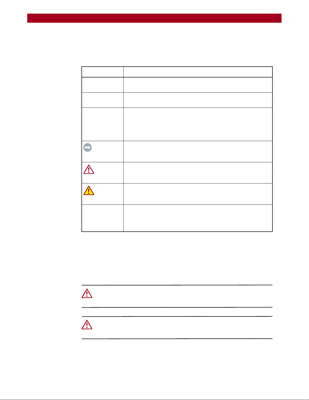
Conventions
This user guide exercises several typographical conventions to help explain how to
use the REO 9100.
Convention Description & Usage
Boldface Words in boldface indicate items to select such as menu items or
command buttons.
Ctrl-Alt-r This type of format details the keys you press simultaneously. In this
example, hold down the Ctrl and Alt keys and press the r key.
NOTE A Note indicates neutral or positive information that emphasizes or
supplements important points of the main text. A note supplies
information that may apply only in special cases—for example,
memory limitations or details that apply to specific versions of a
program.
IMPORTANT An Important note is a type of note that provides information
essential to the completion of a task or that can impact the product
and its function.
Flow Indicator (>) Words in bold font with a greater than sign between them indicate the
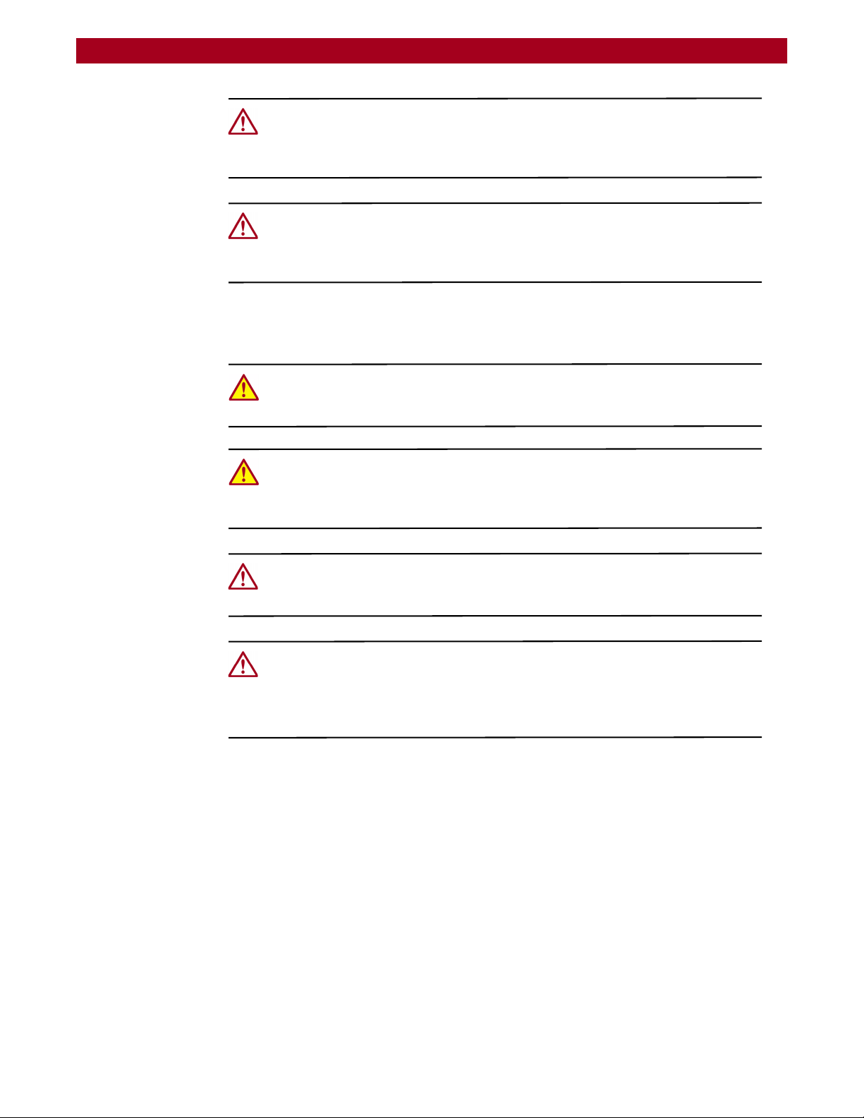
Safety Notices
General Cautions
CAUTION A Caution contains information that the user needs to know to avoid
damaging or permanently deleting data or causing physical damage
to the hardware or system.
WARNING A Warning contains information essential to people’s safety. It
advises users that failure to take or avoid a specific action could
result in physical harm to the user or hardware.
flow of actions to accomplish a task. For example, Setup > Passwords
> User indicates that you should press the Setup button, then the
Passwords button, and finally the User button to accomplish a task.
CAUTION: Before touching any of the appliance components, ground yourself and
take antistatic precautions. Use an antistatic wrist strap and a grounding wire as a
minimum precaution.
CAUTION: Each storage appliance must have a good electrical ground connection
through each power cord, through the building power grid to the point of origin for
the building power source entry.
10400175-101 06/2008 ©2007-2008 Overland Storage, Inc. W ix
Page 10
REO 9100/9100c User Guide Preface
CAUTION: Circuit Overloading—Consideration should be given to the connection of
the equipment to the supply circuit and the effect that overloading of circuits might
have on overcurrent protection and supply wiring. Appropriate consideration of
equipment nameplate ratings should be used when addressing the concern.
CAUTION: Reliable Grounding – Reliable grounding of rack-mounted equipment
should be maintained. Particular attention should be given to supply connections
other than direct connections to the branch circuit (for example, use of power
strips).
Installation Warnings and Notes
WARNING: To prevent personal injury and equipment damage, have someone
assist you during installation. If necessary, reduce the weight of the storage
appliance by removing the disk drives and PS unit.
WARNING: Mechanical Loading—Prevent instability by installing heavier items into
the bottom of the equipment rack. Mounting of the equipment in a rack should be
such that a hazardous condition is not achieved due to uneven loading to prevent
personal injury.
CAUTION: Ensure that your equipment rack is placed in a dust-free, well ventilated
area close to a UPS. Leave enough room behind the rack for servicing and to allow
for sufficient airflow.
CAUTION: Elevated Operating Ambient Temperature—When installed in a closed or
multi-unit rack assembly, the operating ambient temperature of the rack
environment may be greater than the room ambient. Therefore, consideration
should be given to installing the equipment in an environment compatible with the
manufacturer's maximum recommended ambient (TMRA).
10400175-101 06/2008 ©2007-2008 Overland Storage, Inc. W x
Page 11

Preface
Chapter 1 - Introduction and Requirements
Overview ..................................................................................................................................................... 1-1
Reviewing Pre-Installation Requirements ................................................................................................. 1-1
Network .................................................................................................................................................. 1-2
Initiators .................................................................................................................................................. 1-2
Browser ................................................................................................................................................... 1-2
Chapter 2 - Hardware Setup
Register your REO 9100 ............................................................................................................................... 2-1
Preparing the Array and Installation Area ............................................................................................... 2-2
Unpacking the REO 9100 ..................................................................................................................... 2-2
Preparing the Installation Area ............................................................................................................ 2-2
Mounting the Appliance in a Rack .......................................................................................................... 2-3
Installing the Rail Kit .............................................................................................................................. 2-3
Inserting the Appliance ........................................................................................................................ 2-4
Reinstalling Drive Carrier Assemblies ................................................................................................... 2-5
Attaching Cables ....................................................................................................................................... 2-6
Connecting a UPS ...................................................................................................................................... 2-7
Contents
Chapter 3 - Powering Up the Appliance
Verifying Insertion of Disks .......................................................................................................................... 3-1
Enabling Power ........................................................................................................................................... 3-1
Power Supplies ...................................................................................................................................... 3-2
Shutting Down the Appliance ................................................................................................................... 3-4
Backup Power ............................................................................................................................................. 3-4
UPS Power Monitoring .......................................................................................................................... 3-5
Behavior When Connected to UPS ..................................................................................................... 3-5
Supported UPS Models ......................................................................................................................... 3-5
Chapter 4 - Configuring the REO Software
Set Up Network Addressing ....................................................................................................................... 4-1
Logging On ............................................................................................................................................ 4-1
Entering Your Network Configuration Settings ...................................................................................4-3
Configuring GbE Data Ports ...................................................................................................................... 4-4
Configuring FC Data Ports ......................................................................................................................... 4-5
Entering the System Information ............................................................................................................... 4-7
Using RAID Setup ....................................................................................................................................... 4-10
RAID Setup with One or More Expansion Units ................................................................................ 4-10
10400175-101 06/2008 ©2007-2008 Overland Storage, Inc. W xi
Page 12

REO 9100/9100c User Guide Contents
Chapter 5 - Virtual Tape Library Setup
Adding a VTL ............................................................................................................................................... 5-1
Modifying Target Configuration Settings ................................................................................................. 5-4
Adding Initiators .......................................................................................................................................... 5-6
Displaying VTL Status ............................................................................................................................. 5-9
Backing Up the Appliance Configuration ............................................................................................. 5-10
Chapter 6 - Configuring Virtual Devices
Virtual Device Overview ............................................................................................................................ 6-1
Standalone Disk Devices ........................................................................................................................... 6-1
Creating Standalone Disk Devices ..................................................................................................... 6-2
Modifying Standalone Disk Devices ................................................................................................... 6-2
Setting the SCSI Time-Out Value in Windows Environments ............................................................. 6-3
Standalone Virtual Tape Devices ............................................................................................................. 6-4
Creating Standalone Tape Devices ................................................................................................... 6-5
Dynamic Virtual Tapes .................................................................................................................... 6-5
Virtual Tapes .................................................................................................................................... 6-6
Modifying Standalone Tape Devices (Not Multisite) ........................................................................ 6-6
Modifying Multisite Tape Devices ........................................................................................................ 6-7
Add iSCSI Initiator Access for Standalone Devices ................................................................................ 6-9
Add FC Initiator Access for Standalone Devices .................................................................................. 6-10
Configuring a Static Route ...................................................................................................................... 6-10
Removing a Route .............................................................................................................................. 6-11
Add Multisite Initiator Access .................................................................................................................. 6-11
Create Multisite Tape ............................................................................................................................... 6-12
Creating a Multisite Tape Device ..................................................................................................... 6-13
Providing Job Schedule Information ................................................................................................ 6-14
Making a Backup Copy of the Configuration File ................................................................................6-15
Restoring Configuration Settings From Backup File ......................................................................... 6-16
Chapter 7 - Working With the Appliance
Logging On from Any System with Network Access ............................................................................... 7-1
Logging Off the GUI .............................................................................................................................. 7-2
Establishing Communication Between the Systems ............................................................................... 7-2
Connecting the REO Ports ................................................................................................................... 7-2
Looking at How Dynamic Tape Devices Work ........................................................................................ 7-3
Checking Communication with Other Appliances or Systems ............................................................. 7-4
Managing Multi-SitePAC Jobs ............................................................................................................. 7-5
Refreshing the GUI Display ......................................................................................................................... 7-6
Reviewing How the Disk Drives are Numbered ....................................................................................... 7-6
Understanding What the LEDs Represent ................................................................................................ 7-7
Front Panel LEDs .................................................................................................................................... 7-7
Back Panel LEDs .................................................................................................................................... 7-8
Relocating (Moving) an Appliance ......................................................................................................... 7-9
Chapter 8 - Expanding Capacity
Attaching Expansion Arrays ....................................................................................................................... 8-1
Removing Expansion Arrays ...................................................................................................................... 8-3
Expanding Capacity by Adding Disk Drives ............................................................................................ 8-4
10400175-101 06/2008 ©2007-2008 Overland Storage, Inc. W xii
Page 13

REO 9100/9100c User Guide Contents
Chapter 9 - Hardware Compression
Using Compression ..................................................................................................................................... 9-1
GUI Screens Impacted ......................................................................................................................... 9-1
Error Messages ....................................................................................................................................... 9-4
Hardware ..................................................................................................................................................... 9-4
Compression Algorithm ........................................................................................................................ 9-5
Enabling/Disabling Compression ........................................................................................................ 9-5
Appendix A - Basic Troubleshooting
Alerts .............................................................................................................................................................A-1
List of Appliance-Specific Alerts ................................................................................................................A-2
List of Generic SNMP Alerts (Traps) ......................................................................................................A-4
Using the Log Files .......................................................................................................................................A-6
Unable to Access the Appliance .............................................................................................................A-7
REO 9100 Does Not Start Correctly ...........................................................................................................A-7
Unable to Log On to the GUI ....................................................................................................................A-8
Internet Explorer Does Not Redirect from IP Address on Windows Server 2003 .............................A-8
GUI Stops Responding or Displays a Refresh Error ...................................................................................A-9
Addressing an Unresponsive GUI ........................................................................................................A-9
Addressing a Refresh Error Message ...................................................................................................A-9
Out of Resources Message When Trying to Create a VTL ...................................................................A-11
Unexpectedly Logged Off .......................................................................................................................A-11
Unable to Connect to the Disks via Windows Explorer ........................................................................A-12
Perpetual Loop of Audible Alerts on the Appliance ............................................................................A-12
Disabling the Audible Alarm on the Appliance ....................................................................................A-13
Recover System Page Appears in the GUI ............................................................................................A-13
Troubleshooting a Disk Drive Problem ....................................................................................................A-15
Rebuilding a RAID 5 Volume (Without Hot Spare) ..........................................................................A-15
Re-creating a Hot Spare (RAID 5 With Hot Spares) .........................................................................A-16
Purchasing a Spare Disk Drive .................................................................................................................A-16
Impact of a Power Outage .....................................................................................................................A-16
Restoring a Configuration ........................................................................................................................A-17
Appendix B - Specifications
Capacities, Requirements and Limits ....................................................................................................... B-1
Electromagnetic Emissions ........................................................................................................................ B-3
Notice ..................................................................................................................................................... B-3
Industry Canada ................................................................................................................................... B-3
Industrie Canada .................................................................................................................................. B-3
FCC Notice ............................................................................................................................................ B-3
Japan Voluntary Control Council for Interference (VCCI) ..............................................................B-3
Translation ........................................................................................................................................ B-3
Taiwan BSMI Class A Warning .............................................................................................................. B-4
Declaration of Conformity ................................................................................................................... B-5
Appendix C - Protection OS 5.0.1 Options
Design Overview ........................................................................................................................................ C-1
Title Bar .................................................................................................................................................. C-2
Submenu Bar ........................................................................................................................................ C-2
Content Page ...................................................................................................................................... C-2
10400175-101 06/2008 ©2007-2008 Overland Storage, Inc. W xiii
Page 14

REO 9100/9100c User Guide Contents
Create Tab ................................................................................................................................................. C-3
Virtual Tape Library .............................................................................................................................. C-3
Dynamic Virtual Tape .......................................................................................................................... C-5
Virtual Tape ........................................................................................................................................... C-6
Disk ......................................................................................................................................................... C-7
iSCSI Initiator Access ............................................................................................................................ C-7
FC Initiator Access ............................................................................................................................... C-8
Multisite Initiator Access ...................................................................................................................... C-9
Multisite Tape ...................................................................................................................................... C-11
Configuring a Multi-Site Tape ..................................................................................................... C-11
Setting Up a Multi-Site Job Schedule ......................................................................................... C-12
Manage Tab ............................................................................................................................................ C-13
VTL Summary ...................................................................................................................................... C-13
Capacity Summary ...................................................................................................................... C-13
Resources ...................................................................................................................................... C-14
Current VTL Summary .................................................................................................................. C-14
Standalone Device Summary .......................................................................................................... C-15
Initiator Summary ............................................................................................................................... C-15
FC LUN Map ........................................................................................................................................ C-16
Job Manager ..................................................................................................................................... C-17
Job Details .................................................................................................................................... C-17
Modify Multisite Device Job Options ......................................................................................... C-18
Remote Devices ................................................................................................................................. C-20
System Tab ................................................................................................................................................ C-22
System Summary ................................................................................................................................ C-22
Disk Management ............................................................................................................................. C-24
Network Configuration ...................................................................................................................... C-25
Default Gateway ......................................................................................................................... C-25
Management Port ....................................................................................................................... C-25
Data Ports One & Two ................................................................................................................. C-25
FC Network Configuration ................................................................................................................ C-26
Static Route Configuration ............................................................................................................... C-27
Route Configuration .................................................................................................................... C-27
Add A Route ................................................................................................................................. C-28
Remove A Route .......................................................................................................................... C-28
RAID Setup .......................................................................................................................................... C-28
System Configuration ........................................................................................................................ C-29
System Information ...................................................................................................................... C-30
Logon Information ........................................................................................................................ C-30
E-mail Notification ........................................................................................................................ C-30
SNMP Configuration ..................................................................................................................... C-30
Set Time ......................................................................................................................................... C-31
Setting the Time Manually ........................................................................................................... C-32
Setting the Time by NTP Server ................................................................................................... C-32
Disabling NTP Time Synchronization ........................................................................................... C-32
Maintenance ...................................................................................................................................... C-33
Save/Restore Appliance Configuration .................................................................................... C-33
Shut Down/Restart ....................................................................................................................... C-33
System PACs ................................................................................................................................. C-34
10400175-101 06/2008 ©2007-2008 Overland Storage, Inc. W xiv
Page 15

REO 9100/9100c User Guide Contents
Update System ................................................................................................................................... C-34
System Information ...................................................................................................................... C-34
RAID Controller Firmware Updates ............................................................................................. C-35
Fibre Channel Firmware Updates ............................................................................................... C-35
Update Using Downloaded File ................................................................................................. C-35
Troubleshoot Tab ..................................................................................................................................... C-35
System Diagnostics ............................................................................................................................ C-35
Support Request File .................................................................................................................... C-36
Ping an IP Address ........................................................................................................................ C-36
Test Communication with a Remote (Multi-SitePAC) .............................................................. C-36
Test Bandwidth (Multi-SitePAC) .................................................................................................. C-37
Contact Us .......................................................................................................................................... C-37
Appendix D - Backup Networks
Backup Network Concepts .......................................................................................................................D-1
iSCSI Protocol .........................................................................................................................................D-1
iSCSI Architecture ............................................................................................................................D-1
Fibre Channel (FC) ................................................................................................................................D-1
Disk-to-Disk-to-Tape (D2D2T™) Backup Capabilities ........................................................................D-2
Redundant Array of Independent Disks (RAID) .................................................................................D-5
Tape Emulation .....................................................................................................................................D-6
Virtual Tape Libraries .............................................................................................................................D-6
Appendix E - Initiators and Targets
About Initiators and Targets ...................................................................................................................... E-1
iSCSI Naming Conventions .................................................................................................................. E-1
iSCSI-Qualified Names .................................................................................................................... E-2
IEEE iSCSI Names .............................................................................................................................. E-2
How Targets and Initiators are Associated ........................................................................................ E-2
Appendix F - Using Multi-SitePAC
Overview of Multi-SitePAC for REO Appliances ...................................................................................... F-1
Basic Multi-SitePAC Function ............................................................................................................... F-1
Multi-SitePAC Restrictions ..................................................................................................................... F-2
Setting Up a Multi-SitePAC Application ................................................................................................... F-3
Backing Up the Data and Data Transfer ............................................................................................ F-3
Performing a Restore Operation ......................................................................................................... F-7
Appendix G - Customer Support
Registering Your Product .......................................................................................................................... G-1
Locating Additional Information for Your Product ................................................................................. G-2
Updating the Appliance ........................................................................................................................... G-2
Determining the Version of the Protection OS ................................................................................. G-3
Checking For and Downloading Updates ........................................................................................ G-3
Updating the Appliance ..................................................................................................................... G-4
Glossary and Acronym List
Index
10400175-101 06/2008 ©2007-2008 Overland Storage, Inc. W xv
Page 16

CHAPTER
1
Overview
Introduction and Requirements
The Overland REO 9100 Disk-Based Backup and Recovery Appliance with
Protection OS™ embeds data protection intelligence, and delivers a core set of
volume and device virtualization, management, and connectivity features. It
supports both iSCSI and Fibre Channel (FC) connectivity.
The REO 9100 uses a Web-based interface and can be easily configured as a
virtual tape library (VTL) and/or any mix of standalone virtual tape drives,
Dynamic Virtual Tape (DVT) drives, or virtual disks. Using DVT, users can create
virtual tape cartridges that automatically expand or shrink as needed to match
the exact capacity requirements of the backup operation.
The REO 9100 comes in two versions: the basic appliance with optional software
compression (REO 9100) or the always-on hardware compression version (REO
9100c). The REO 9100c comes with special data compression hardware that offers
high performance compression and decompression capabilities for use with any
virtual tape device. It provides 2:1 or better compression without sacrificing
performance.
NOTE: Due to the availability of the superior hardware compression feature, software
compression is not supported on the REO 9100c. Also, hardware compression is
only available for virtual tape drives; it is not an available option for disk targets.
By default, compression is enabled and is available for all virtual tape devices on
the REO 9100c. The REO 9100c also implements in-band host application enable
or disable requests, and monitors the compression status for the virtual tape
devices.
NOTE: Hardware compression settings cannot be changed manually.
Reviewing Pre-Installation Requirements
Before attempting to operate the REO 9100 with your backup servers, verify that
your network meets the minimum requirements specified in the following
sections.
10400175-101 06/2008 ©2007-2008 Overland Storage, Inc. W 1-1
Page 17

REO 9100/9100c User Guide Introduction and Requirements
Network
For best results, Overland strongly recommends that you use a dedicated GbE
network to share the storage resources on the REO 9100 among multiple backup
servers.
To ensure optimum performance, always use the appropriate patch cables to
connect the REO 9100 to the backup-server storage network. To select the
appropriate cables, use the following guidelines:
• If you intend to use GbE, you must use Category 5e (or better) cables for
GbE connections. You can use either straight-through or cross-over cables.
• If you intend to connect the REO 9100 to a 100BaseT or faster network, use
Category 5 (or better) shielded cables.
• The maximum length of cable for any Ethernet-based network connection is
328 feet (100 meters).
NOTE: For smaller environments, you can attach the REO 9100 directly to a single
application or backup server by using standard Category 5e cables without the
use of a switch.
Initiators
Browser
Initiators are required to communicate with the REO 9100 targets (devices). Each
backup server that will interface with the REO 9100 must be equipped with a
software- or hardware-based initiator. The REO 9100 supports any computing
platform with an available iSCSI initiator, either in software or using an iSCSI
HBA (it must comply with iSCSI draft 20, version 1.0).
The REO 9100 GUI is a Web-enabled program that requires the use of cookies,
Java applets, and Java scripts. Make sure that the Web browser you use is
configured to allow these items.
10400175-101 06/2008 ©2007-2008 Overland Storage, Inc. W 1-2
Page 18
CHAPTER
(E-Mail) (Password)
2
The main steps involved in setting up the REO 9100 include:
1. Registering the unit to activate technical support.
2. Preparing by unpacking the appliance and reviewing safety guidelines.
3. Installing the appliance in a rack.
4. Inserting the disk drive carriers into the chassis.
5. Connecting the REO to the management LAN.
Register your REO 9100
Hardware Setup
Before installing your new unit, it is essential that you activate your REO
warranty. Technical and warranty support are not available until this is done:
1. Go to the Overland Technical Support web site at:
http://support.overlandstorage.com/
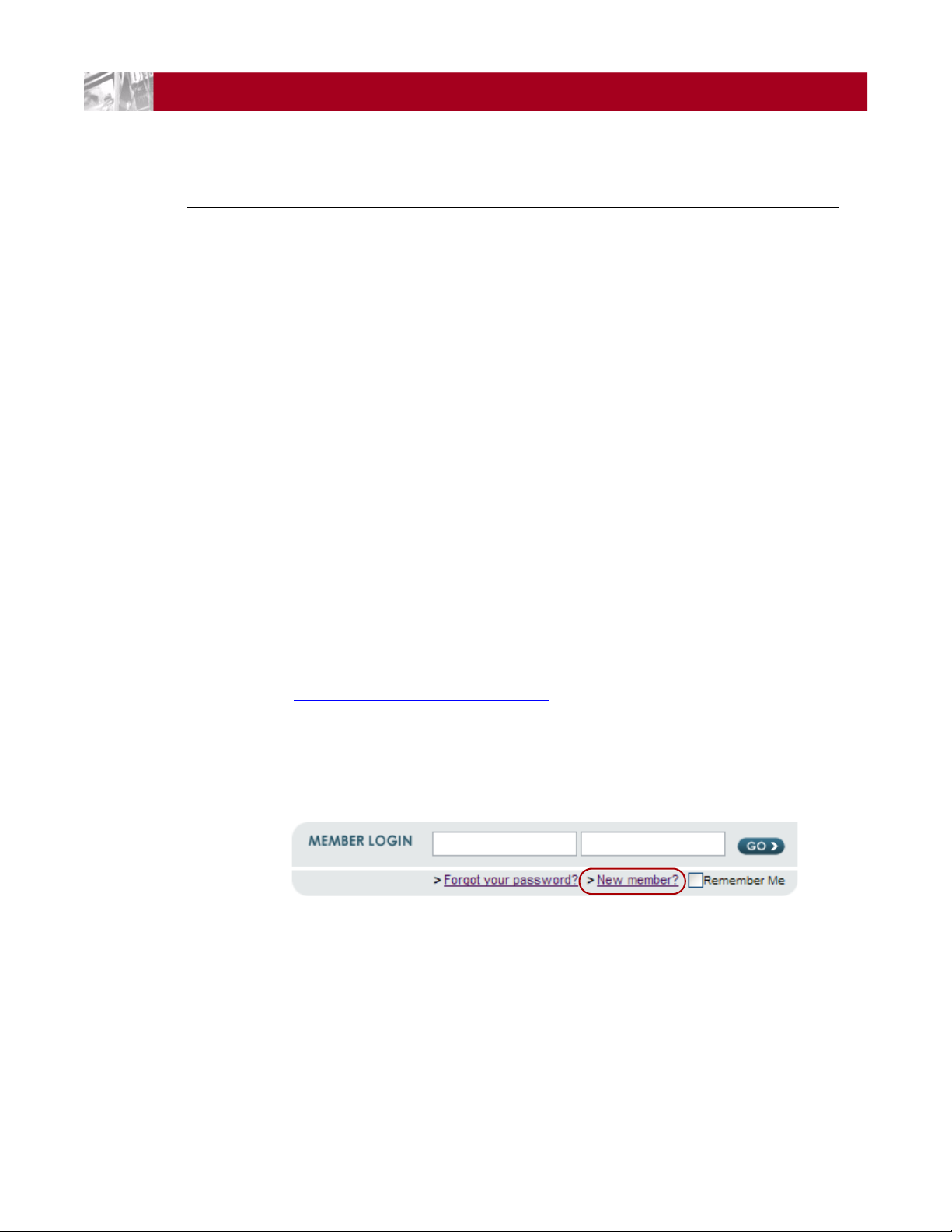
2. Using the MEMBER LOGIN, log in to the site.
NOTE: If you are not yet a member, click the New member? link and follow the
instructions. It’s free!
Figure 2-1: Login and Sign-up Links
3. From the menu on the left, select My Products > Add or Register a
Product, and follow the on-screen instructions.
10400175-101 06/2008 ©2007-2008 Overland Storage, Inc. W 2-1
Page 19

REO 9100/9100c User Guide Hardware Setup
Preparing the Array and Installation Area
WARNING: Due to the weight of each rack-mounted unit when it is fully extended,
you should install units in the rack from the bottom up. Extending a unit that has
empty spaces beneath it might cause the rack to tip forward or might result in
personal injury. Overland recommends that at least two people support and slide
the unit in the rack.
Unpacking the REO 9100
Because of its weight when loaded with disk drives, the Overland Storage REO
9100 appliance ships in two boxes.
Box one contains:
• REO chassis
• Power cords
• Rack-mount slide rail kit and hardware
• REO 9100 Documentation CD
• REO 9100 Quick Start Guide
Box two contains:
• 24 disk carriers, some or all with disk drives installed
NOTE: Depending on which version of the product that you purchased, either 12 or
24 of the carriers come with drives installed.
IMPORTANT: Before unpacking the unit, ensure that the area is free from conditions
that cause electrostatic discharge (ESD). Discharge static electricity from your body
by touching a known grounded surface. Also, avoid touching pins, leads, or circuitry.
Preparing the Installation Area
Review the following guidelines before positioning the appliance physically within
your network.
• Make sure there is unrestricted air flow around the unit and through the
vents in the sides and rear of the case.
• Route external cables so that they can be connected easily without blocking
air vents or impeding air flow.
• Protect the appliance from extreme temperature and humidity. Overland
recommends that you install the unit in a clean, air-conditioned
environment where water and moisture cannot enter the case of the
appliance. Keep the air as free from dust as possible.
• Protect the appliance from physical shock and vibration.
• Make sure that the inlet air temperature within the rack remains below the
specified limit of 95°F (35°C).
• Keep the appliance and cabling away from sources of electrical noise since
electromagnetic fields can interfere with the signals on copper cabling and
introduce errors, therefore slowing down the network.
10400175-101 06/2008 ©2007-2008 Overland Storage, Inc. W 2-2
Page 20
REO 9100/9100c User Guide Hardware Setup
R
A
9
-
0
0
0
2
Bracket
Outer & Middle Rails
Front of Rack
Outside of Rack
Front Ver tical
Rack Rail
Rear Vertical
Rack Rail
Nuts Nuts
R
A
9
-
0
0
0
2
Nut or Nut Bar
Bracket Screw & Washer
Outside Edge
Mounting the Appliance in a Rack
Your REO 9100 appliance comes with a set of slide rails for mounting the chassis
in the 19-inch rack. The REO unit has a 5U form factor. The inner rail segments
are already attached to the chassis.
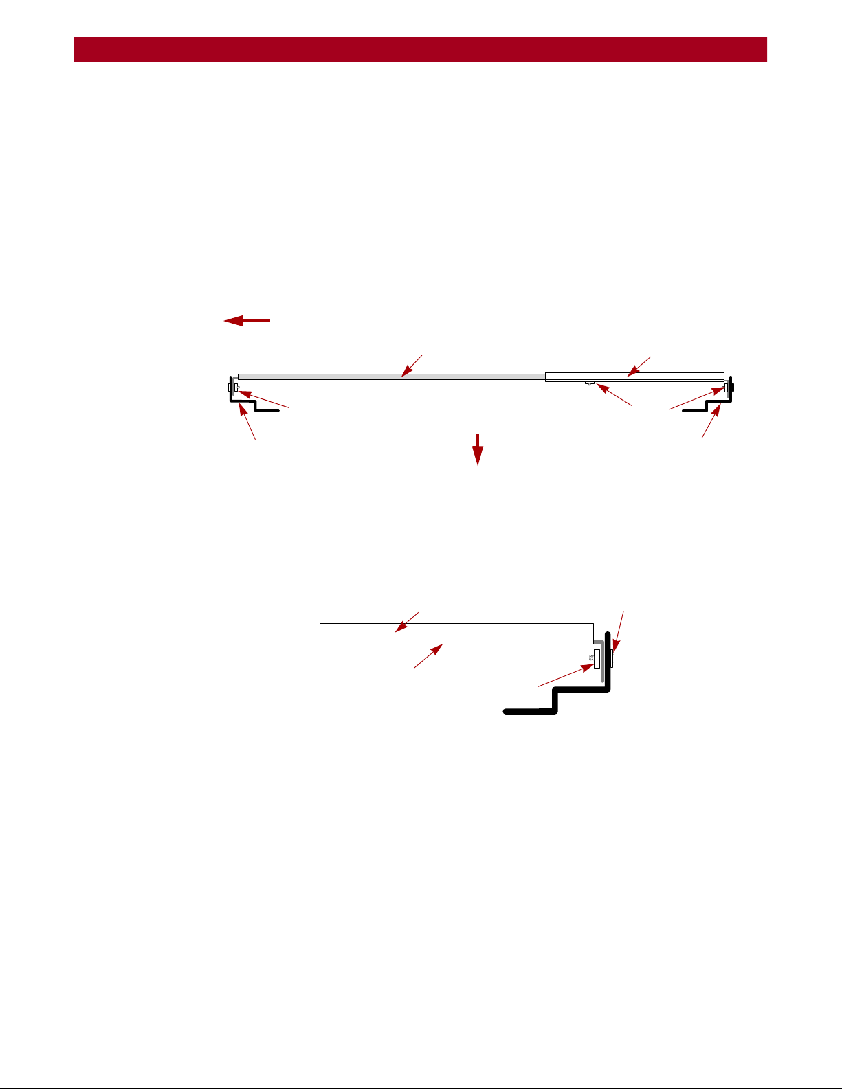
Installing the Rail Kit
Use these steps to install the rail kit in a square-holed RETMA rack (Figure 2-2):
NOTE: For a threaded-hole rack, omit the washers.
Figure 2-2: Outer Rail & Bracket Assembly and Positioning
1. Identify and mark the screw holes on the front and rear vertical rails of the
rack where the slide rails will be installed.
2. Loosely install rear bracket inside the rear vertical rack rail (Figure 2-3)
using two sets of screws, washers, and nuts (or bar nut) supplied.
Figure 2-3: Attached the Bracket to the Rack
3. For a standard RETMA rack, loosely attach two screws through the 9th
holes from the rear of the bracket (
Figure 2-4) using two nuts or a nut bar.
Do not tighten the screws yet.
10400175-101 06/2008 ©2007-2008 Overland Storage, Inc. W 2-3
Page 21
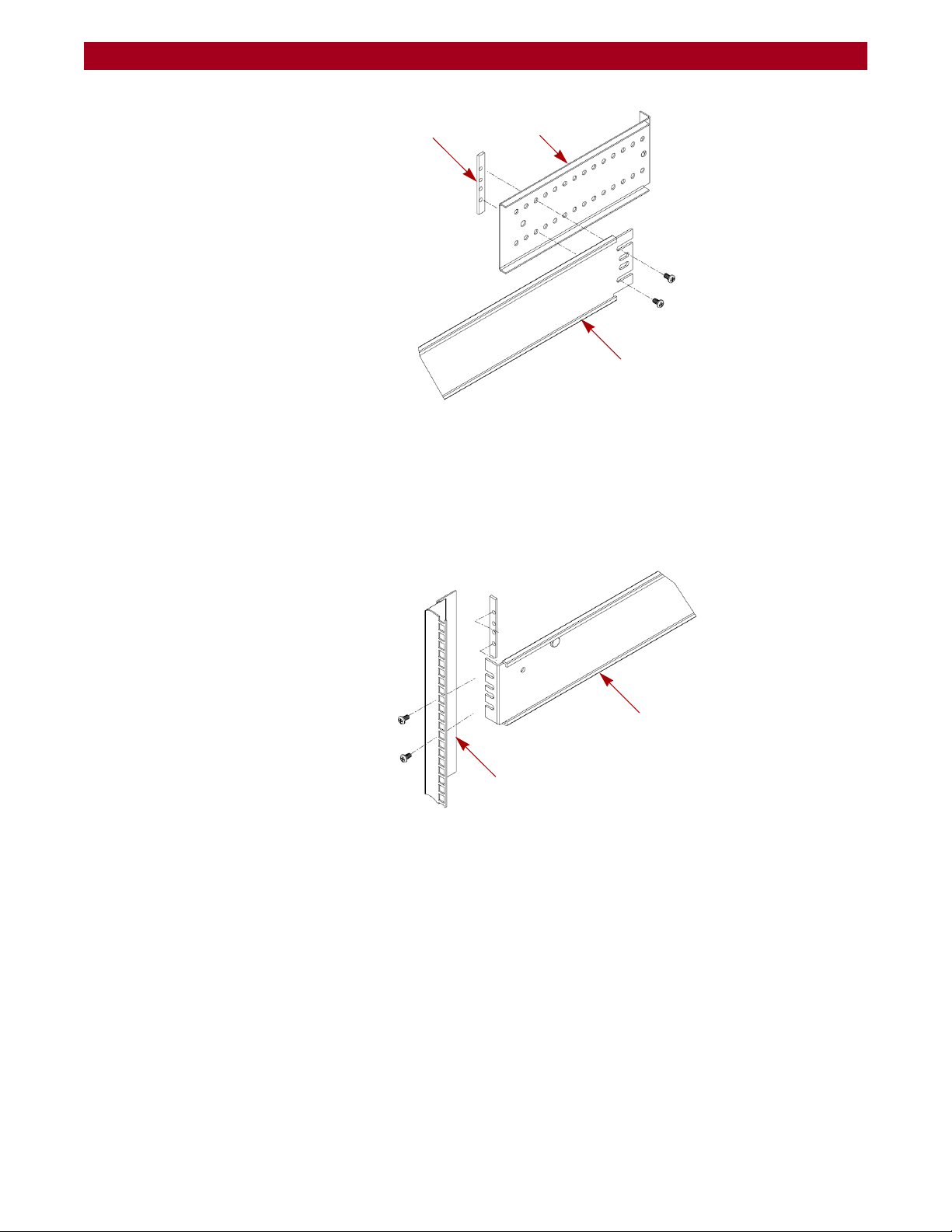
REO 9100/9100c User Guide Hardware Setup
BracketNut Bar
Outer/Middle
Rail Assembly
Outer/Middle
Rack Rail
Front Vertical
Rail Assembly
Outer/Middle
Figure 2-4: Location of Bracket Screws for Outer/Middle Rail Assembly
4. Slide the non-flange end of the outer/middle rail assembly onto screws on
rear bracket and align the flange end inside the front vertical rail to the
appropriate holes.
5. Attach the outer/middle rail assembly to the front vertical rack rail
(
Figure 2-5) using two sets of screws, washers, and nuts (or a bar nut).
Figure 2-5: Attaching Outer/Middle Rail Assembly
6. Verify that the rail assemblies are installed properly and tighten the screws
holding the rail assembly to the rack.
7. Tighten the screws that secure the bracket to the outer/middle rail
assembly.
8. Repeat Steps 2–7 for the other rail assembly.
Inserting the Appliance
1. Pull out the middle slides from the front of the rack so that they lock in the
extended position (click).
10400175-101 06/2008 ©2007-2008 Overland Storage, Inc. W 2-4
Page 22
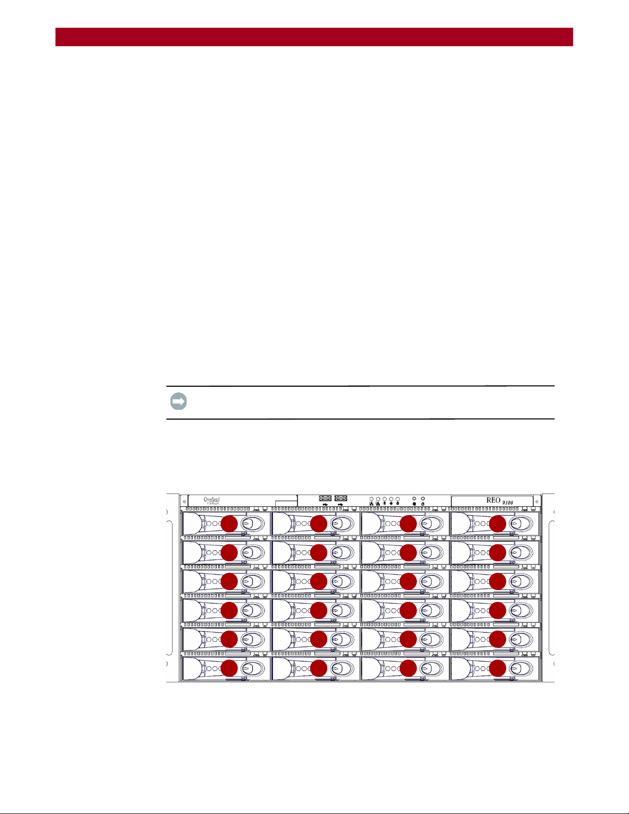
REO 9100/9100c User Guide Hardware Setup
00
04
08
12
16
20
01
05
09
13
17
21
02
06
10
14
18
22
03
07
11
15
19
23
2. Using a mechanical lifter or two people, lift the appliance to its install height
and engage the inner slides mounted on the chassis with the middle slides
protruding from the rack.
3. Slide the appliance in until it stops.
4. Simultaneously press both lock buttons on the inner rails and slide the
appliance in until it stops again.
5. Press the same lock buttons again and slide the appliance all the way into
the rack.
6. Slide the appliance in and out several times, ensuring that the inner and
outer slide locks engage and the
chassis does not bind against the slides. If
binding occurs:
a. Remove the appliance.
a. Loosen the screws that secure the slides to the front and the rear rails of
the rack.
b. Readjust the slide positioning as needed and retighten the screws.
c. Reinsert the appliance and verify that it does not bind.
7. Slide the appliance all the way into the rack and secure the appliance
flanges with screws (left and right side) to the rack.
Reinstalling Drive Carrier Assemblies
IMPORTANT: To maintain proper airflow and cooling, a disk drive or a blank drive
carrier must be installed in every slot.
The disk drive assemblies (disks mounted in carriers) are packaged separately,
which allows you to insert them into the array chassis after you have installed the
chassis in the rack. Each disk carrier contains a label that identifies the slot into
which you must insert it.
10400175-101 06/2008 ©2007-2008 Overland Storage, Inc. W 2-5
Figure 2-6: REO 9100 Slot Numbering
Page 23
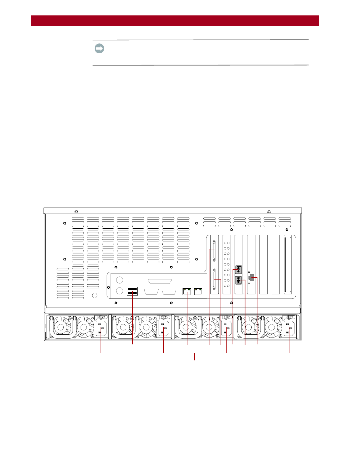
REO 9100/9100c User Guide Hardware Setup
R
A
9
-
0
0
0
3
1 - USB Ports
2 - Data Port 2 (RJ-45)
3 - Data Port 1 (RJ-45)
4 - SCSI Ports 1
5 - SCSI Port 0
6 - FC Port 1
7- FC Port 0
8 - Management Port
9- AC Power Connectors
124
5
678
9
3
IMPORTANT: Do not remove the drives from the drive carriers. The RAID array is
preconfigured so failure to install the disks in the corresponding slots may result in
the need to create a new configuration.
To install disk carriers in chassis
1. Insert the first disk carrier into the appropriate slot in the chassis.
2. With the lever in the open position, push firmly on both sides of the carrier
to ensure that the latch and connector are fully seated.
3. Press the lever in until it clicks into the locked position.
This draws the carrier fully into the slot and seats it properly inside the
chassis.
4. Repeat these steps for each disk carrier.
Attaching Cables
All cabling and power connections are located on the rear panel of your REO
appliance (Figure 2-7). Connections are available for Ethernet, USB, and serial
cabling. All unit cooling exhaust is handled through the rear panel.
Figure 2-7. REO 9100 Rear Panel Connections
10400175-101 06/2008 ©2007-2008 Overland Storage, Inc. W 2-6
Page 24

REO 9100/9100c User Guide Hardware Setup
Once the unit is secured in the rack and the disk drives installed, you are ready to
attach the cables that connect the REO appliance to your host system and power
source.
1. Plug the network connection into the Ethernet port.
Using a Category 5e (or better) cable, connect Data Port 1 on the appliance
to the management LAN.
2. Connect any other cables to the appropriate plugs as shown (Figure 2-7).
3. Attach the four power cords to the AC Power sockets on the REO back
panel, but do not connect the cords to any AC power sources yet.
Powering up the unit is covered in the next chapter.
Connecting a UPS
IMPORTANT: Overland recommends connecting your REO 9100 to an
Uninterruptible Power Supply (UPS).
NOTE: For more information on using a UPS, refer to “Backup Power” on page 3-4.
1. Make sure the REO 9100 is powered down and unplug the AC cords from the
main AC power source.
2. Connect the USB cable from the UPS to the USB port on the REO 9100 back
panel.
3. Plug the AC power cords from the REO 9100 into the AC sockets on the UPS.
4. Plug the AC power cord from the UPS into a main AC power source.
5. Turn on the UPS.
10400175-101 06/2008 ©2007-2008 Overland Storage, Inc. W 2-7
Page 25

CHAPTER
Powering Up the Appliance
3
The main steps involved in enabling power to the REO 9100 include:
1. Making sure that the disks are correctly inserted in the appliance.
2. Connecting the power cords to a power source and enabling power.
3. Shutting down the appliance.
4. Using an Uninterruptible Power Supply (UPS).
Verifying Insertion of Disks
Because your appliance is configured with two RAID 5 with Hot Spare arrays, it is
important that the disks are inserted in the correct slots in the appliance.
all of the same capacity. The drives in one unit can be a different capacity than those in
the other units as long as all the drives in that unit are the same size.
Make sure that the disks are seated correctly to prevent an error state during the
power-on procedure. For more information, see
Assemblies” on page 2-5.
Enabling Power
situation is resolved. Overland recommends that you use separate power mains for the
power sources.
Power problems can be the cause of serious failures and downtime on your
network. Ensure that the power input to your system is clean and free from sags
and surges to avoid unforeseen network outages. Overland strongly recommends
that you install power conditioning and an adequately rated uninterruptible
power supply (UPS), especially in areas prone to blackouts, power dips, and
electrical storms.
IMPORTANT: The REO 9100 head unit must be populated with drives that are all of
the same capacity. Also, expansion units must be fully populated with drives that are
“Reinstalling Drive Carrier
IMPORTANT: All four power cords must be connected. If one of the cords is
disconnected or malfunctioning, the appliance beeps continuously until the
10400175-101 06/2008 ©2007-2008 Overland Storage, Inc. W 3-1
Page 26

REO 9100/9100c User Guide Powering Up the Appliance
R
A
9
-
0
0
0
3
Fans Alarm Reset Release Latch Thumbscrew HandleLED AC Socket
The REO 9100 is intended to be grounded. Ensure it is connected to earth ground
during normal use.
Power Supplies
Each of the four power supply modules contain:
• A socket for an AC line cord.
• A two-color LED for indicating the status of the power supply.
• When all outputs are available, the LED becomes green.
• If the power supply fails, the LED becomes red.
• A latch with a thumbscrew for releasing the power supply.
• A handle for pulling the power supply out of the appliance.
• A pair of fans to prevent overheating.
• A feature that verifies the following (if not detected, an alarm signal
sounds):
• All output voltages V1 to V5 are within regulation.
• The fans are operating normally.
• The internal temperature of the power supply is normal.
An Alarm Reset switch (red push button) is located on the back panel, in the
location shown in
Figure 3-1.
Figure 3-1: Enabling Power to REO Appliance
CAUTION: To power on a REO system with an expansion unit, refer to Chapter 8,
“Expanding Capacity.” If you do not complete these steps in this order, the
appliance might start in an error state.
10400175-101 06/2008 ©2007-2008 Overland Storage, Inc. W 3-2
Page 27

REO 9100/9100c User Guide Powering Up the Appliance
Power Button
To power up the appliance:
1. Plug each of the power cords into a separate AC power source.
IMPORTANT: If power is automatically enabled when you attach the cords to
an AC power source, shut down the appliance before continuing with the
setup process. For details on shutting down an appliance, see “Shutting Down the
Appliance” on page 3-4
2. To power up the REO 9100, press and hold the power button for about 1
second, which starts the power-up sequence.
The power switch is located in the top area of the front panel above the third
column of disks. The power switch is a momentary contact device that needs
to be held to begin the power-up sequence.
Figure 3-2: Power Button Location
After you turn the power on, the REO 9100 performs a power-on self-test
(POST) process. Following successful completion of the POST, which takes
several minutes, you should hear 3 beep tones spaced about 1 second apart.
If you are unable to hear the tones in your physical environment, wait
approximately five minutes before continuing.
IMPORTANT: On startup, the appliance might reach an error state and begin
an endless loop of alerts. The pattern (2 beeps separated by a 1-second
delay) repeats every 4 seconds. If this occurs, turn the appliance off and then
back on. For more information, see “Perpetual Loop of Audible Alerts on the
Appliance” on page A-12
3. After you hear the POST completion beep tones, proceed to the configuration
steps outlined in the next chapter,
“Configuring the REO Software” on
page 4-1.
IMPORTANT: You must leave the appliance ON while completing the
configuration process for your application and backup servers.
10400175-101 06/2008 ©2007-2008 Overland Storage, Inc. W 3-3
Page 28

REO 9100/9100c User Guide Powering Up the Appliance
Shutting Down the Appliance
IMPORTANT: To ensure preservation of data on the REO 9100, you should not turn
off the appliance using the power button. Always use the Shut Down option located
in the REO 9100 GUI.
NOTE: If you are setting up a new appliance and you did not complete the steps in the
proper order or power was automatically enabled, you might not have access to
the Shut Down option in the REO 9100 GUI.
To shut down the appliance via the GUI:
1. Verify that no backup/restore jobs are running.
2. In the REO 9100 GUI, under System Menu, click Maintenance.
3. On the Maintenance page, under Shut Down/Restart, click Shut Down.
4. When the confirmation message appears, click OK.
To shut down the appliance without GUI access:
1. Press and release the power button on the front of the appliance quickly
(1 second or less) to initiate a graceful software-system shutdown process.
2. Wait up to 1 minute to see if the appliance responds.
3. If the appliance does not shut down after the first attempt, repeat
Backup Power
In order to protect your data from loss due to sudden power interruption, your
REO 9100 supports the use of an external UPS. The REO 9100 monitors the UPS
via the USB port (reporting the charge level on the System Summary page). When
the REO 9100 senses a low UPS power condition, it initiates a graceful shutdown
that completes before the UPS runs out of battery power.
The LED for power will turn off after the shutdown process is finished.
Steps 1–2 a second time.
CAUTION: Pressing and holding the power button for 4 seconds or more causes an
immediate hardware-shutdown that might result in the loss of data on the
appliance if there are any active read-, write-, or management-operations.
Whenever possible, turn off the appliance using the REO 9100 GUI or the graceful
shutdown method described earlier. If you must use the immediate hardwareshutdown method, make sure that you first stop all host- and management-serverrelated activity.
10400175-101 06/2008 ©2007-2008 Overland Storage, Inc. W 3-4
Page 29
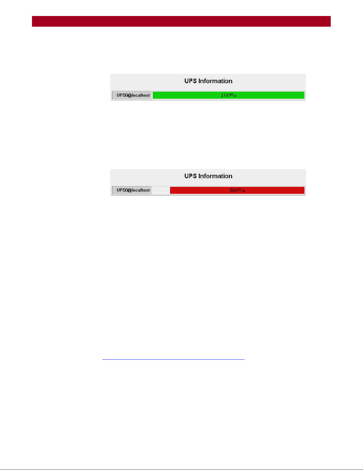
REO 9100/9100c User Guide Powering Up the Appliance
UPS Power Monitoring
When the REO appliance detects that it is connected to a UPS, it displays the UPS
Information (
• When the REO is receiving power from the main AC source, the indicator
bar is green. A complete green bar and 100% indication mean that the UPS
battery is fully charged.
• When the main AC power is interrupted and the REO is powered by the
UPS, the indicator bar turns red. The red bar and the numeric indication
grow smaller as the UPS battery charge goes down.
Figure 3-3) at the bottom of the System Summary page.
Figure 3-3: System Summary Page UPS Information
• When the primary AC power is restored, the indicator bar turns green. The
green bar and the numeric indication grow toward 100% as the UPS battery
charges itself up.
Behavior When Connected to UPS
A REO 9100 with a UPS works normally as long as the main AC power is supplied.
When the main AC power is interrupted and the REO 9100 detects battery power,
it initiates a graceful shutdown in such a way as to be completed before the battery
power runs out.
Once initiated, the shutdown continues to completion, even if the AC power has
been restored. Upon completion of the shutdown, and when the AC power has been
restored, the REO 9100 does not restart automatically. Use the Power button on
the front panel to restart the REO 9100.
Supported UPS Models
UPS support has been verified with the APC Smart-UPS 2200VA. Other UPS
devices that connect via the same driver can be found at:
http://www.networkupstools.org/compat/stable.html
Figure 3-4: REO Running on UPS Power
10400175-101 06/2008 ©2007-2008 Overland Storage, Inc. W 3-5
Page 30

CHAPTER
4
Configuring the REO Software
The main steps involved in configuring the management environment include:
1. Entering default gateway and Management Port addresses.
2. Entering the Data Port information.
3. Entering Fibre Channel and system information.
4. Configuring logon information.
5. Configuring alerts.
6. Setting the applicable time information.
7. Connecting the appliance to the application and backup servers, SAN for the
backup servers, or FC.
8. Installing software client drivers or storage adapters for iSCSI or FC access
on systems involved in the backup process.
The images shown in the following sections were captured on a Windows system.
The screens might appear slightly different if you are using a UNIX-based system.
Set Up Network Addressing
Before using your REO 9100, you must configure the network communication
addresses. The Management Port connects the REO 9100 to the Management
LAN. A workstation or computer connected to the LAN can then be used to
manage the REO 9100.
IMPORTANT: The Management Port and both Data Ports must be on a separate
subnets.
Logging On
When setting up your REO 9100, you must initially connect to Data Port 1 and
configure the network settings.
1. Directly connect a laptop or other computer to Data Port 1.
2. Configure the NIC in the laptop to be on the 10.0.0.0 network except
for
10.0.0.1.
3. Launch a Web browser on the connected laptop.
10400175-101 06/2008 ©2007-2008 Overland Storage, Inc. W 4-1
Page 31

REO 9100/9100c User Guide Configuring the REO Software
Appliance Name
Submenu
Content Page Header
Main Menu Tabs
Buttons
(Content Page)
Help Link
Logout Link
4. In your Web browser, connect to the default IP address of 10.0.0.1.
The REO 9100 Login screen is displayed (Figure 4-2):
Figure 4-1: REO 9100 Logon Screen
5. Enter the following in case-sensitive format:
• Logon Name: Administrator
• Password: system
The REO 9100 GUI appears (Figure 4-2).
10400175-101 06/2008 ©2007-2008 Overland Storage, Inc. W 4-2
Figure 4-2: REO 9100 Default GUI Screen
Page 32

REO 9100/9100c User Guide Configuring the REO Software
When you first access the GUI, it displays the System Summary page. The main
menu tabs are located at the lower left side of the title bar. Selecting a tab name
displays the submenu buttons in the side bar. The content page on the right
displays the information that corresponds to the submenu option you click.
Entering Your Network Configuration Settings
1. Verify the System tab is selected.
2. Click Network Configuration to display the option screen (Figure 4-3).
Figure 4-3: Network Configuration Screen
3. In the Default Gateway section, enter the address you want to use and
click Apply.
4. In the Management Port section, enter the address and subnet mask you
want to use and click Apply.
5. Click the Logout link (Figure 4-4) on the right in the Title Bar.
Figure 4-4: Logout Link Location
6. Using a Category 5 (or better) cable, connect the REO Management Port to
a switch or hub on the Management LAN.
7. In a browser on the Management computer, enter the Management Port IP
address set in
Step 4.
10400175-101 06/2008 ©2007-2008 Overland Storage, Inc. W 4-3
Page 33

REO 9100/9100c User Guide Configuring the REO Software
8. Logon to the GUI using the same user name and password.
NOTE: If the computer attached to the Management Port is unable to access the
GUI, reconnect the laptop and use the 10.0.0.1 address to double-check the
information you specified for the Default Gateway and Management Port.
Continue the configuration process by configuring the GbE data ports as described
in the next section,
“Configuring GbE Data Ports.”
Configuring GbE Data Ports
Data Port 1 and Data Port 2 are GbE data ports used for block-level data transport
between your backup servers and the REO 9100. Data Port
fully interchangeable before configuration.
IMPORTANT: The Management Port is on the Management LAN. Use Data Port 1
and Data Port 2 on separate subnets of the backup network. Data Port 1 and Data
Port 2 each requires an available static IP address within their respective subnets. The
REO can also be managed via either of the data ports. Entering either data port IP
address in your browser displays the REO 9100 GUI.
1 and Data Port 2 are
If you have one or two backup servers, you can connect each one directly to one of
the data ports on the REO 9100. The backup servers must have a GbE port. If you
have more than two backup servers, you must make these connections through a
GbE switch.
NOTE: The port currently being used to access the REO 9100 cannot be configured
while in use. If you are logged into Data Port 1 via the default IP,
you can configure only the Management Port or Data Port 2. To configure Data
Port 1, you must be logged into the Management Port or Data Port 2.
To configure the GbE ports:
1. At the System tab, click Network Configuration.
Because you are accessing the GUI through the Management Port, those
options are not changeable.
2. In the Data Port 1 section:
a. Enter an appropriate static IP address and subnet mask.
b. Click Apply.
3. In the Data Port 2 section:
a. Click Enable.
b. Enter an appropriate static IP address and subnet mask.
c. Click Apply.
If you purchased the FC-enabled REO 9100, continue the configuration process by
entering the FC information described in the next section; otherwise, proceed to
the subsequent section,
10400175-101 06/2008 ©2007-2008 Overland Storage, Inc. W 4-4
“Entering the System Information” on page 4-7.
Page 34

REO 9100/9100c User Guide Configuring the REO Software
Configuring FC Data Ports
If your REO appliance is set up for FC, do the following procedure:
1. At the System tab, click FC Configuration (Figure 4-5).
Figure 4-5: FC Configuration Page
2. For each FC port (the appliance provides two), select the applicable settings
from the Set Link Speed and Set Link Topology lists.
• For link speed, select Auto, 1 GB, 2 GB, or 4 GB.
NOTE: Overland Storage recommends that you configure a fixed speed
of 1, 2, or 4 GB.
• For topology, select Auto, Fabric/Point-to-Point (N_Port), or Loop
(NL_Port).
10400175-101 06/2008 ©2007-2008 Overland Storage, Inc. W 4-5
Page 35

REO 9100/9100c User Guide Configuring the REO Software
3. If you want to use a specific loop ID (Hard Alpa), check Enable/Disable box
and enter the desired number.
The following are the valid addresses:
0x01 0x02 0x04 0x08 0x0F 0x10 0x17 0x18 0x1B 0x1D
0x1E 0x1F 0x23 0x25 0x26 0x27 0x29 0x2A 0x2B 0x2C
0x2D 0x2E 0x31 0x32 0x33 0x34 0x35 0x36 0x39 0x3A
0x3C 0x43 0x45 0x46 0x47 0x49 0x4A 0x4B 0x4C 0x4D
0x4E 0x51 0x52 0x53 0x54 0x55 0x56 0x59 0x5A 0x5C
0x63 0x65 0x66 0x67 0x69 0x6A 0x6B 0x6C 0x6D 0x6E
0x71 0x72 0x73 0x74 0x75 0x76 0x79 0x7A 0x7C 0x80
0x81 0x82 0x84 0x88 0x8F 0x90 0x97 0x98 0x9B 0x9D
0x9E 0x9F 0xA3 0xA5 0xA6 0xA7 0xA9 0xAA 0xAB 0xAC
0xAD 0xAE 0xB1 0xB2 0xB3 0xB4 0xB5 0xB6 0xB9 0xBA
0xBC 0xC3 0xC5 0xC6 0xC7 0xC9 0xCA 00xCB 0xCC 0xCD
0xCE 0xD1 0xD2 0xD3 0xD4 0xD5 0xD6 0xD9 0xDA 0xDC
0xE0 0xE1 0xE2 0xE4 0xE8 0xEF
4. Click Apply.
Continue with “Entering the System Information,” next.
10400175-101 06/2008 ©2007-2008 Overland Storage, Inc. W 4-6
Page 36

REO 9100/9100c User Guide Configuring the REO Software
Entering the System Information
1. At the System tab, click System Configuration (Figure 4-6).
Figure 4-6: Initial System Configuration Page
2. In the System Information section, enter the System Name (the default
is “REO”) and click Apply.
Enter up to 16 characters to name the appliance. You can use a mixture of
letters, numbers, and hyphens (–). Overland recommends that you change
the default name, especially if you use multiple appliances on your network.
3. In the Logon Information section, enter a user name and password:
IMPORTANT: If you choose to keep Administrator as your user name,
Overland strongly recommends that you change the password to protect your
network from unauthorized users. The user name and password are casesensitive.
a. User Name (required). Enter a name using up to 30 alphanumeric
characters (do not use colons or spaces). The first character of the name
must be either an upper (A–Z) or lowercase (a–z) alphabetical character.
b. Password (optional but highly recommended). Enter a new password
using up to 30 alphanumeric characters (do not use spaces or Ctrl-key
characters).
10400175-101 06/2008 ©2007-2008 Overland Storage, Inc. W 4-7
Page 37

REO 9100/9100c User Guide Configuring the REO Software
c. Retype Password. Enter the password again.
d. Click Apply.
4. In the E-mail Notification section, click Enable and enter the following
(
Figure 4-7):
Figure 4-7: Initial System Configuration Page with E-mail Enabled
a. SMTP Server IP Address. Using dotted decimal notation, enter the IP
address of your mail server.
b. From Address. Enter the e-mail address from which the alert will be
sent. This address must use the same domain as the mail server specified
for SMTP Server IP Address.
c. Address for all messages. Enter the e-mail address to which alerts
should be sent (for example, the e-mail address for the network
administrator or the e-mail list address for a group of backup
administrators).
d. Address for critical messages only. Enter the e-mail address to
which only critical alerts should be sent
.
e. To verify that the messaging system is configured correctly, click Test.
If the test e-mail message is not successfully sent and received, correct
the applicable information, and repeat the test. If the test is
unsuccessful, make sure that you are using a valid SMTP Server IP
address, and that the address is working properly.
f. Click Apply.
10400175-101 06/2008 ©2007-2008 Overland Storage, Inc. W 4-8
Page 38

REO 9100/9100c User Guide Configuring the REO Software
Select Time
Zone first;
then, set time,
or enter IP
address of
Time Server
<IP address>
5. If you use network-management software that takes advantage of SNMP, in
the SNMP Configuration section, click Enable to view the entries
(
Figure 4-8):
Figure 4-8: Configuring SNMP
a. Read-Only Community String. Enter the name of the string (the
default is public). You can enter up to 256 alphanumeric characters.
IMPORTANT: Because public is the default string for a large number of
network appliances, Overland strongly recommends that you change it.
b. Trap IP Address. Using dotted decimal notation, enter up to four IP
addresses that function as destinations.
c. To verify that the system is configured correctly, click Test Trap.
d. Click Apply.
e. To download the MIB file for this SNMP configuration, press Download
MIB.
The compressed, downloaded file mibs.tgz contains the required SNMP
MIB for receiving traps. Place this file in a secure location.
NOTE: The file must be saved with a .tgz extension.
6. In the Set Time section, select the applicable settings (Figure 4-9):
Figure 4-9: Set the Time Zone and the Time
a. Select the appropriate local Time Zone using the drop-down list and
click Apply in the Current Time Zone section.
10400175-101 06/2008 ©2007-2008 Overland Storage, Inc. W 4-9
Page 39

REO 9100/9100c User Guide Configuring the REO Software
IMPORTANT: Set the Time Zone first. This establishes the correct time for
the appliance whether the time is set here, or via NTP server.
The REO 9100 defaults to the UTC (formerly Greenwich Mean Time)
time zone. If you are in a different time zone, you must set the time zone
for accurate local time. This ensures that any communication that occurs
(for example, if an e-mail is automatically generated) reflects the correct
date and time for the appliance.
For more information on setting the time, see “Set Time” on page C-31.
b. Set the time on the current appliance or via NTP server:
• To set time on this appliance: select the appropriate current time
settings; then, click Apply in the Current Date and Time section.
• To set time via NTP server: enter the IP address of the NTP
protocol server on your network; then, click Enable NTP. The
Current Date and Time section displays only the current date and
time with no options.
• To disable NTP server time: click Disable NTP. The Current
Date and Time section re-displays the date and time options and the
Current Network Time section returns to its original state.
Using RAID Setup
You can use the RAID Setup feature under the System tab to select a different
RAID configuration. The REO appliance ships configured as a RAID
Spare but also supports the basic RAID
In a RAID configuration, how the volumes are arranged depends on whether you
are using an appliance that contains 12 or 24 physical disks, and it depends on
whether those disks are 250
The appliance also contains two physical controllers. If you are using 12 physical
disks, all 12 are assigned to the first controller; if you are have 24 disks, the second
set of 12 disks is assigned to the second controller. If you add 12 disks to an
existing 12 disk configuration, the second 12 disks are assigned to the second
controller.
RAID Setup with One or More Expansion Units
When you request the RAID Setup function on a REO head unit with one or more
expansion units connected, the process cleans up and deletes all connected RAID
Sets, but only the head unit recreates its RAID Sets. The RAID Sets for each
expansion appliance must be manually added. See
Capacity.”
GB, 500 GB, 750 GB, or 1 TB in size.
5 with Hot
5 configuration.
Chapter 8, “Expanding
10400175-101 06/2008 ©2007-2008 Overland Storage, Inc. W 4-10
Page 40

CHAPTER
5
Virtual Tape Library Setup
The key feature of the REO 9100 is its ability to emulate a physical type library so
existing backup software can easily manage the REO appliance, track and move
virtual tape cartridges, and maintain retention policies.
The main steps involved in creating a Virtual Tape Library (VTL) include:
1. Determining the type of RAID Set you want to use.
2. Adding a virtual tape library and drive type that you want to emulate.
3. Setting the target information.
4. Identifying the initiators.
5. Making a backup copy of the information so that your configuration is
preserved.
Adding a VTL
NOTE: Up to six (6) VTLs can be created on each REO appliance running Protection OS
version 5.0.x.
1. Click the Create tab. The default screen is the Create Virtual Tape Library
screen (Figure 5-1).
Figure 5-1: Create Virtual Tape Library Screen
10400175-101 06/2008 ©2007-2008 Overland Storage, Inc. W 5-1
Page 41

REO 9100/9100c User Guide Virtual Tape Library Setup
2. Make the necessary changes to the fields as follows:
a. In the Descriptive Name section, do one of the following:
• Leave the Automatic check box selected to have the REO
software specify the name of the VTL. It uses the prefix “vl” followed
by a number, beginning with 0, for example, “vl0” for the first VTL.
• Clear the check box. In the text box that appears to the right, type a
name using up to 32 alphanumeric characters.
b. If desired, select the Emulation Template you want to use as the
default settings for the new VTL.
The template that you select changes the default number in the Drive
Count and Cartridge/slot Count fields. You can manually change any of
the default settings.
• Select NEO 2000 to create one drive and 30 cartridges.
• Select NEO 4100 to create two drives and 60 cartridges.
• Select NEO 4200 to create four drives and 120 cartridges.
c. In the Drive Type section, select the type of drive to emulate. The drive
type you select determines the default DVT Capacity Limit:
• Select LTO-2 to create drives with DVT Capacity Limit of 200GB.
• Select LTO-3 to create drives with DVT Capacity Limit of 400GB.
• Select LTO-4 to create drives with DVT Capacity Limit of 800GB.
• Select DLT-7000 to create drives with DVT Capacity Limit of 35GB.
This selection also reduces the default number of cartridges to 26.
d. In the Bar Code Seed section, do one of the following:
IMPORTANT: The bar code seed text cannot be changed once the VTL is
created. Verify your selections before clicking Create.
• If you want the REO Protection OS to specify the first bar code label
and automatically generate subsequent labels, leave the Automatic
check box selected.
• If you want to use your own naming convention, you can clear the
check box and, in the text box that appears to the right of the check
box, type the seed code using six alphanumeric characters. Lowercase
letters are converted to uppercase when the VTL is created.
The sequencing of the codes begins with the last character listed. For
example, if you manually entered a seed of AAAAAA, the next code is
AAAAAB. When the code reaches AAAAAZ, it rolls the second to the last
character and starts over (AAAABA, AAAABB, and so on). If you
manually entered a seed of 111111, the next number would
automatically be 111112.
10400175-101 06/2008 ©2007-2008 Overland Storage, Inc. W 5-2
Page 42

REO 9100/9100c User Guide Virtual Tape Library Setup
IMPORTANT: If you plan to create VTLs on multiple appliances and
associate them with the same media-management database in your
backup software, make sure to clear the Automatic check box, and manually
enter a starting label that ensures the creation of a unique labeling scheme
for the V TL.
For example, you might use REA000 as the seed for a VTL on REO
appliance A, REB000 for a VTL on REO appliance B, REC000 for a VTL on
REO appliance C, and so on. (The automatic option uses the same labeling
scheme for all VTLs on each REO appliance, which results in the same set of
labels being reported for each VTL to your backup software.
e. Still in the Bar Code Seed section, from the Characters list, select the
applicable number of bar code characters (6 or 8) to display to your
backup application.
If you select 8 characters, the system automatically appends two
characters to the label to indicate the drive type selection:
Drive Type Characters Appended
LTO-2 L2
LTO-3 L3
LTO-4 L4
DLT7000 D7
f. In the Drive Count field, if you want to change the default number of
virtual tape-drives allocated for the VTL, enter the new number in the
text box.
g. In the Cartridge/Slot Count box, if you want to change the default
number of virtual tape cartridges (and corresponding slots) allocated for
the VTL, enter the new number in the text box.
The REO Protection OS automatically creates a Dynamic Virtual Tape
device for each cartridge.
h. Enter the DVT Capacity Limit for each cartridge.
The default value is 200 GB, the same capacity as an LTO-2 cartridge. If
you change the drive type, the DVT Capacity Limit default also changes.
IMPORTANT: Making this value too large will over-subscribe the REO
appliance, which means the VTL could exhaust the available space of the
appliance even though the VTL has remaining capacity. Consider dividing the
total remaining capacity by the number of cartridges in your new VTL to
determine an appropriate DVT capacity limit.
NOTE: After you click Create, you can only increase the number of drives and
cartridges assigned to the VTL. To decrease either setting, the current
VTL must be deleted and a new one created.
10400175-101 06/2008 ©2007-2008 Overland Storage, Inc. W 5-3
Page 43

REO 9100/9100c User Guide Virtual Tape Library Setup
3. Click Create. A progress message appears regarding the time required for
REO to create the VTL.
When the new VTL is created, the VTL Summary screen (Manage tab) is
displayed (Figure 5-2 on page 5-4).
Figure 5-2: Current VTL Summary screen Listing New VTLs
Modifying Target Configuration Settings
To view or change the VTL configuration:
1. Under the Manage tab, click VTL Summary.
2. Click the appropriate VTL Summary Modify button under Target
Configuration to view the information (
IMPORTANT: The default SCSI Product ID automatically identifies the VTL as
a NEO Series device. Do not change this setting unless your backup software
requires a different setting.
Figure 5-3).
10400175-101 06/2008 ©2007-2008 Overland Storage, Inc. W 5-4
Page 44

REO 9100/9100c User Guide Virtual Tape Library Setup
Figure 5-3: Modify Target Configuration Screen
NOTE: If your REO does not support Fibre Channel, the FC LUN column
displays n/a.
3. For a REO 9100 basic unit without hardware compression, if your backup
software supports a hardware compression feature for use with tape and you
want to emulate that feature, select the software Compression check box.
For optimal backup performance, leave this check box cleared; to maximize
the backup storage capacity, select this check box. This option applies to all
virtual cartridges on the VTL.
NOTE: On REO 9100c models, the box is checked and grayed-out.
4. If necessary, make any changes to the VTL Settings:
• DVT Capacity Limit
• Drive Count
• Cartridge/Slot Count
• Descriptive Name
• Bar Code String Width
10400175-101 06/2008 ©2007-2008 Overland Storage, Inc. W 5-5
Page 45

REO 9100/9100c User Guide Virtual Tape Library Setup
NOTE: The bar code seed cannot be changed once the VTL is created.
5. To change the default target name of a device, type the new name in the
iSCSI Target Name box.
All targets must have an iSCSI name. The REO software automatically
enters a name that begins with the name of the VTL and includes the MAC
address of the device.
6. Before clicking Commit, note the following if you need this information for
your backup software:
• Device Name. Displays the name of the device automatically assigned
by the software.
• FC LUN. Displays the Fibre Channel (FC) logical unit number (LUN)
automatically assigned to the device by the software.
• SCSI SN. Displays the Small Computer System Interface (SCSI) serial
number (SN) automatically assigned to the device by the software.
7. Click Commit.
The VTL Summary screen is redisplayed.
You can now add the initiator access to the VTL by completing the steps outlined
in the next section,
“Adding Initiators.”
Adding Initiators
NOTE: You can assign up to 16 initiators to each VTL device.
Now that you created a VTL, you assign initiator access to it. Initiator access to
the devices (targets) is established via initiators. You can assign up to eight
initiators to each disk device. Standalone devices must first exist before you can
assign an initiator to them.
IMPORTANT: Due to iSCSI’s limitations with device sharing, plan your storage
system configuration such that there is one iSCSI initiator to a disk device. If your
configuration requires multiple iSCSI initiator connections to one device, then sharing
software is required to avoid data corruption and connection loss
To add an Initiator to a VTL:
1. Under the Manage tab, select VTL Summary.
2. Click the appropriate Current VTL Summary Modify button under
Initiator Configuration to view the information (
Figure 5-4 on page 5-7).
10400175-101 06/2008 ©2007-2008 Overland Storage, Inc. W 5-6
Page 46

REO 9100/9100c User Guide Virtual Tape Library Setup
Figure 5-4: Modify Initiator Configuration Screen
3. Click Add Initiator (top left).
4. In the Select Connection Type field, click iSCSI or, if available, FC (iSCSI is
the default connection type).
5. Depending on the connection type selected, follow the appropriate
procedure:
• For an iSCSI initiator (Figure 5-5):
Figure 5-5: Add Initiator Screen with iSCSI Selected (default)
• Select an existing initiator from the Initiator Names drop-down list.
10400175-101 06/2008 ©2007-2008 Overland Storage, Inc. W 5-7
Page 47

REO 9100/9100c User Guide Virtual Tape Library Setup
NOTE: If you use the Initiator Names list to select an existing initiator, there is
only one name in the list, and you are using Internet Explorer on a
Windows 2000 system, you might need to select the name a second
time before it will automatically complete the name and address fields.
• In the iSCSI Initiator Name field, enter a unique name (up to 223
alphanumeric characters) of an authorized initiator for the target.
NOTE: The fully qualified iSCSI name is assigned by the manufacturer of either
the software initiator or the storage adapter on your backup server.
The iSCSI initiator name entered here must match the name of the iSCSI
initiator on the associated backup server.
If the maximum number of initiators has already been defined for a VTL
device, the iSCSI Initiator Name field is greyed out. You can only add an
initiator by using the drop-down Initiator Names list.
• For an FC initiator (Figure 5-6):
Figure 5-6: Add Initiator Screen with FC Selected
• Select an existing initiator from the Initiator Names drop-down list.
• In the FC Initiator WWNN and WWPN boxes, enter the official
node and port names of the authorized initiator (host system).
NOTE: You can retrieve the initiator WWNN and WWPN by using the specific FC
host adapter management software utility or by querying the name
server on the FC switch.
6. In the Select Devices for this Initiator section, if you do not want the
initiator to access all devices, select the applicable device from the list.
10400175-101 06/2008 ©2007-2008 Overland Storage, Inc. W 5-8
Page 48

REO 9100/9100c User Guide Virtual Tape Library Setup
7. Click Commit to create the initiator.
You are returned to the Modify Initiator Configuration screen.
8. If you want to add another initiator, repeat Steps 3–7.
9. After you are done creating initiators, click Commit on the Add Initiator
Configuration screen.
Displaying VTL Status
To view the status of the VTL:
1. Under the Manage tab, select VTL Summary.
2. Click the appropriate Current VTL Summary Status button under Display
to view the status information (
Figure 5-4 on page 5-7).
Figure 5-7: VTL Status Display
The VTL Status page displays a Device Summary and a Cartridge Map.
10400175-101 06/2008 ©2007-2008 Overland Storage, Inc. W 5-9
Page 49

REO 9100/9100c User Guide Virtual Tape Library Setup
NOTE: If your device does not support Fibre Channel, n/a is displayed in the FC LUN
column.
3. To return to the VTL Summary page, click Go To Library Summary.
Backing Up the Appliance Configuration
The appliance includes a feature that saves all configuration-related information,
such as virtual libraries, devices, and host-system information, to a location
specified by you. (It does not save system or network information.)
After you have completed tasks such as creating targets and initiators, Overland
strongly recommends that you create backup copies of the basic appliance
configuration. Overland also recommends that you complete these steps whenever
you add a new library or tape device or change configuration settings.
For details on backing up the REO appliance configuration settings, refer to
“Making a Backup Copy of the Configuration File” on page 6-15.
10400175-101 06/2008 ©2007-2008 Overland Storage, Inc. W 5-10
Page 50

CHAPTER
Configuring Virtual Devices
6
Using the Protection OS software, you can configure disks on a REO appliance to
function either as standalone disk devices or as virtual tape devices.
The main steps involved in setting up virtual devices on your REO appliance are:
1. Understanding the types of disk and tape virtual devices.
2. Configuring appropriate devices for your applications.
3. Making a backup copy of the information so that your configuration is
preserved.
Virtual Device Overview
The Protection OS software pools all the REO disks of each RAID together to
create devices of any size. This way, you can use each device either in its native
disk format, a virtual-tape format, or any combination of the two. You can create
up to a total of 64 devices using any combination of disk LUNs and virtual tape
devices.
NOTE: If you allocate all available space on the appliances to the devices, the system
automatically sends one critical-level alert regarding the storage pool. If you
restart the appliance, the system automatically sends the message again.
Standalone Disk Devices
At any time, unused disk space can be configured as an independent virtual disk
device. This device can fill all available space on the REO appliance. For example,
after all VTLs are set up, any extra disk space can be configured as a standalone
disk for extra storage. This standalone disk can be as large as 16 TB.
NOTE: Support is available for disk devices that are greater than 2 TB (up to 16 TB).
10400175-101 06/2008 ©2007-2008 Overland Storage, Inc. W 6-1
Page 51

REO 9100/9100c User Guide Configuring Virtual Devices
Creating Standalone Disk Devices
1. Under the Create tab, click Disk (Figure 6-1 on page 6-2).
Figure 6-1: Create Disk Screen
2. Accept the default or enter a new Size of Device.
3. Accept the default or enter a new iSCSI Target Name.
4. Click Create.
The Standalone Device Summary screen is displayed.
Modifying Standalone Disk Devices
NOTE: Disk devices can only be expanded in size. To make a smaller device, the old
device must first be deleted and then recreated using the smaller size setting.
1. If necessary, under the Manage tab, click Standalone Device Summary
(Figure 6-2).
Figure 6-2: Standalone Device Summary Screen
2. To change the iSCSI target name:
a. Click Modify.
b. Enter a new iSCSI target name.
c. Click Apply.
d. At the message about shutting down initiators, click OK.
The Standalone Device Summary screen is redisplayed.
10400175-101 06/2008 ©2007-2008 Overland Storage, Inc. W 6-2
Page 52

REO 9100/9100c User Guide Configuring Virtual Devices
3. To expand the disk size:
a. Click Expand.
b. In the Expand Device By field, enter the number of additional gigabytes
you are adding to the existing size.
c. Click Expand.
d. At the message about shutting down initiators, click OK.
The Standalone Device Summary screen is redisplayed.
4. To remove a disk device:
a. Click Remove.
b. At the warning message (Figure 6-3), click OK (or Cancel).
Figure 6-3: Disk Removal Warning Message
The Standalone Device Summary screen is redisplayed.
Setting the SCSI Time-Out Value in Windows Environments
If you intend to use your REO 9100 in a Windows environment, be aware that
there are certain operating conditions in which disk time-out errors might occur.
These errors usually result in the system reporting a disk failure for the
associated REO 9100 disk drive or drives.
These errors might be reported as iSCSIPrt errors in the System Log of the Event
Viewer. Examples include an Event ID 9, “Target did not respond in time for a
SCSI request,” and Event ID 39, “Initiator sent a task management command to
reset the target.” Other symptoms might include “Lost Delayed Write Data”
system error messages or similar error messages related to the REO 9100 disk
drives.
NOTE: These disk time-out errors can occur because the default I/O time-out value for
Windows is 20 seconds, which is not sufficient to support the default iSCSI
protocol time-out value of 60 seconds. When you install and set up your REO
9100, Overland strongly recommends that you set this value to 60 seconds.
10400175-101 06/2008 ©2007-2008 Overland Storage, Inc. W 6-3
Page 53

REO 9100/9100c User Guide Configuring Virtual Devices
To set the time-out value to 60 seconds:
1. On the Windows system, run regedit.
CAUTION: If you edit the registry incorrectly, you might cause serious
problems that require you to reinstall your operating system. Edit the registry
at your own risk. Prior to making any changes, refer to the following Microsoft
Knowledge Base article:
http://support.microsoft.com/default.aspx?scid=kb;en-us;322755
2. In HKEY_LOCAL_MACHINE\System\CurrentControlSet\
Services\Disk, edit or add the TimeOutValue entry to set it to 60 seconds
in decimal format (0000003c in hexadecimal).
• To edit the value for the TimeOutValue entry if it already exists, double-
click the entry, enter the new value, and click OK.
• To add the TimeOutValue entry if it does not yet exist, right-click
anywhere in the list of values, and then click New > DWORD value.
Name the new value TimeOutValue, and then double-click it to edit the
setting.
Figure 6-4: Registry Editor with TimeOutValue Added
Standalone Virtual Tape Devices
If you intend to create virtual tape or dynamic virtual tape devices, note the
following:
• As with standard tape devices, a specific driver (on a Windows system) or
changes to a system configuration (on a UNIX system) might be required to
operate with your selected backup software. For more information, check the
Overland Web site (www.overlandstorage.com) for Application Notes related
to your specific backup software.
• If you enable software compression on the basic REO 9100, be aware that
various factors (such as the speed of your backup server, source devices, or
network) can significantly affect performance. Additionally, the existing
state of the files you are backing up (for example, whether the files are
already compressed) can affect the level of compression that might be
achieved. Consider these factors when you determine the applicable settings
for your backup environment.
10400175-101 06/2008 ©2007-2008 Overland Storage, Inc. W 6-4
Page 54

REO 9100/9100c User Guide Configuring Virtual Devices
• Once a tape virtual device is configured, it cannot be changed into a virtual
disk device.
Creating Standalone Tape Devices
You can create either variable-size dynamic virtual tapes or fixed-sized virtual
tapes.
Dynamic Virtual Tapes
1. Under the Create tab, click Dynamic Virtual Tape (Figure 6-5).
Figure 6-5: Create Dynamic Virtual Tape Screen
2. Select the Drive Type to emulate from the Drive Type drop-down list:
LTO-2, LTO-3, LTO-4, or DLT7000.
3. If software compression is desired on a basic unit, check Enable Tape
Compression. (Option is grayed out with hardware compression.)
4. Accept the default or enter a new Dynamic Tape Maximum Size.
NOTE: Leave the setting at “0” GB to allow it to use up to 2047 GB (maximum) or all
available space, which ever is smaller.
5. Accept the default or enter a new iSCSI Target Name.
6. Click Create.
The Standalone Device Summary screen is displayed.
10400175-101 06/2008 ©2007-2008 Overland Storage, Inc. W 6-5
Page 55

REO 9100/9100c User Guide Configuring Virtual Devices
Virtual Tapes
1. Under the Create tab, click Virtual Tape (Figure 6-6).
Figure 6-6: Create Dynamic Virtual Tape Screen
2. Select the Drive Type to emulate from the Drive Type drop-down list:
LTO-2, LTO-3, LTO-4, or DLT7000.
3. Accept the default or enter a new Size of Device.
4. If software compression is desired on a basic unit, check Enable Tape
Compression. (Option is grayed out with hardware compression.)
5. Accept the default or enter a new iSCSI Target Name.
6. Click Create.
The Standalone Device Summary screen is displayed.
Modifying Standalone Tape Devices (Not Multisite)
NOTE: Tape devices can only be expanded in size. To make a smaller device, the old
device must first be deleted and then recreated using the smaller size setting.
1. If necessary, under the Manage tab, click Standalone Device Summary
(Figure 6-7).
Figure 6-7: Standalone Device Summary Screen
2. To change the iSCSI target name:
a. Click Modify.
b. Enter a new iSCSI target name.
10400175-101 06/2008 ©2007-2008 Overland Storage, Inc. W 6-6
Page 56

REO 9100/9100c User Guide Configuring Virtual Devices
c. Click Apply.
d. At the message about shutting down initiators, click OK.
The Standalone Device Summary screen is redisplayed.
3. To expand the size of a fixed-sized virtual tape:
NOTE: Since a DVT uses dynamic sizing, it expands (and contracts) its size
automatically.
a. Click Expand.
b. In the Expand Device By field, enter the number of additional gigabytes
you are adding to the existing size.
c. Click Expand.
d. At the message about shutting down initiators, click OK.
The Standalone Device Summary screen is redisplayed.
4. To remove a virtual tape device:
a. Click Remove.
b. At the warning message, click OK (or Cancel).
The Standalone Device Summary screen is redisplayed.
Modifying Multisite Tape Devices
1. Under the Manage tab, click Standalone Device Summary (Figure 6-7 on
page 6-6).
NOTE: If you enabled compression during transfer, the device appears in Italics in the
Device Type column on the Standalone Summary Page shown on page 6-6.
The size of a device reflects the space that is available on a disk.
2. To change the multisite device parameters, click Modify (Figure 6-8 on
page 6-8).
10400175-101 06/2008 ©2007-2008 Overland Storage, Inc. W 6-7
Page 57

REO 9100/9100c User Guide Configuring Virtual Devices
Figure 6-8: Modify Multisite Device Screen
3. Modify the multisite device in one or all of the following ways:
a. Enable Tape Compression: Select the check box to enable, clear the
check box to disable.
b. Maximum Duration of Job: Enter a larger or smaller value to increase
or decrease the number of hours that this job runs before cancellation.
c. Compress During Transfer: Select the check box to compress the data
during the mirroring process and store compressed data on the central
appliance; clear the check box to send without compression.
d. Connection Time-Out: Enter a larger or smaller value to increase or
decrease the number of minutes before a connection times out.
e. WAN Bandwidth Management: Enter a larger or smaller value to
increase or decrease the amount of the I/O delay during data transfer.
f. Job Schedule Information: Select the appropriate drop-down lists to
change the mirror type, or change the schedule.
4. Click Apply.
10400175-101 06/2008 ©2007-2008 Overland Storage, Inc. W 6-8
Page 58

REO 9100/9100c User Guide Configuring Virtual Devices
Add iSCSI Initiator Access for Standalone Devices
To be able to use a REO virtual device, it must first be connected to an initiator.
1. Under the Create tab, click iSCSI Initiator Access (Figure 6-7).
Figure 6-9: Standalone Device Add iSCSI Initiator Screen
2. In the iSCSI Initiator Name field, enter a unique name (up to 223
alphanumeric characters) of an authorized initiator for the target.
NOTE: The fully qualified iSCSI name is assigned by the manufacturer of either the
software initiator or the storage adapter on your backup server.
The iSCSI initiator name entered here must match the name of the iSCSI
initiator on the associated backup server.
If the maximum number of standalone initiators has already been defined
for a device, the iSCSI Initiator Name field is greyed out. You can only add an
initiator by using the drop-down Initiator Names list.
3. In the Device Name List section, select one or more applicable devices from
the list.
4. Click Create to create access for the initiator.
The Add iSCSI Initiator Access for Standalone Devices screen is reset and
redisplayed.
5. If you want to add access for more iSCSI initiators, repeat Steps 1–4.
10400175-101 06/2008 ©2007-2008 Overland Storage, Inc. W 6-9
Page 59

REO 9100/9100c User Guide Configuring Virtual Devices
Add FC Initiator Access for Standalone Devices
For appliances running Fibre Channel, use the following procedure to add FC
initiator access.
1. Under the Create tab, click FC Initiator Access (Figure 6-7).
Figure 6-10: Standalone Device Add FC Initiator Screen
2. In the FC Initiator WWNN and WWPN boxes, enter the official node and
port names of the authorized initiator (host system).
NOTE: You can retrieve the initiator WWNN and WWPN by using the specific FC host
adapter management software utility or by querying the name server on the
FC switch.
3. In the Device Name List section, select one or more applicable devices from
the list.
4. Click Create to create access for the initiator.
The Add FC Initiator Access for Standalone Devices screen is reset and
redisplayed.
5. If you want to add access for another FC initiator, repeat Steps 1–4.
Configuring a Static Route
To use the Multi-SitePAC application, you must establish a network route through
which the devices communicate. A static route is a network path that is dedicated
to a specific port and destination: it does not change. You can configure up to four
static routes.
NOTE: The addresses used to specify the route must exist prior to establishing the
route.
To establish a static route for the appliances:
1. Enter the IP address of the network destination in the Network
Destination field.
The network destination is the port on the remote appliance that the central
appliance uses for communication.
10400175-101 06/2008 ©2007-2008 Overland Storage, Inc. W 6-10
Page 60

REO 9100/9100c User Guide Configuring Virtual Devices
Figure 6-11: Adding a Route on the Static Route Configuration Page
2. Enter the subnet mask value associated with this route entry into the
Subnet Mask field (i.e.,255.255.255.0)
3. Enter the IP address of the gateway associated with the route entry in the
Gateway field.
4. Click Add to add this route.
5. At the two confirmation messages that appear, click OK.
Removing a Route
To remove a single route, select the route and click Remove. To remove all of the
routes, click Remove All. Click OK when the confirmation messages appear to
remove the route or routes from the list.
Add Multisite Initiator Access
An iSCSI multisite initiator establishes communication between the central
appliance and the remote appliance in a Multi-SitePAC application. Create the
initiator access to set up communication before you create the multisite tape
device.
IMPORTANT: A route must exist between the remote REO data port and the central
REO data port before you create initiator access. For information on setting up a
route, see “Configuring a Static Route” on page 6-10.
1. Under the Create tab, click Multisite Initiator Access (Figure 6-12).
NOTE: An existing iSCSI Initiator cannot be used as a Multisite initiator on the same
appliance. Multi-SitePAC is not available for appliances that feature
hardware compression (REO 9100c).
10400175-101 06/2008 ©2007-2008 Overland Storage, Inc. W 6-11
Page 61

REO 9100/9100c User Guide Configuring Virtual Devices
Figure 6-12: Standalone Device Add iSCSI Initiator Screen
2. In the iSCSI Initiator Name of Remote Host field, enter a unique name
(up to 223 alphanumeric characters) of an authorized initiator for the target.
NOTE: The fully qualified iSCSI name is assigned by the manufacturer of either the
software initiator or the storage adapter on your backup server.
The iSCSI initiator name entered here must match the name of the iSCSI
initiator on the associated backup server.
3. In the IP Address on Remote Appliance for Control Interface field,
enter the IP address of the port on the remote appliance that the central
appliance uses for communication with it.
The central appliance uses this address to configure multisite tape devices
and to instruct any multisite jobs to start or stop.
4. In the IP Address on Central Appliance for Data Transfer field, select
the IP address (port) on the central appliance that receives multisite data
from the remote appliance.
5. Click Create to create the initiator.
The Standalone Device Summary screen is displayed.
6. To add another multisite initiator, repeat Steps 1–5.
Create Multisite Tape
The multisite tape device is a Dynamic Virtual Tape (DVT) device that is created
on both the central and remote appliances in a Multi-SitePAC application.
Multisite uses DVTs to allow the data, and its transfer, to expand over time.
NOTE: Currently. you can create only LTO2 multisite tape devices.
10400175-101 06/2008 ©2007-2008 Overland Storage, Inc. W 6-12
Page 62

REO 9100/9100c User Guide Configuring Virtual Devices
Creating a Multisite Tape Device
Each central/remote pair can be configured for 10 multisite tape devices. To set up
the backup job from the remote appliance to the central appliance via a multisite
tape device:
1. Under the Create tab, click Create Multisite Tape.
Figure 6-13. Create Multisite Tape Page with Job Schedule Information
2. In the Multisite Initiator field, select one of the currently configured
multisite initiators from the drop-down list.
3. Select the Enable Tape Compression check box to maximize backup
storage capacity; otherwise, for optimal backup performance, leave the check
box cleared.
NOTE: Your backup software should support a hardware compression feature for
use with tape.
4. In the Dynamic Tape Maximum Size field, enter the maximum size (in
GB) allowed for this tape device. To use the maximum space available, leave
the default entry, 0.
NOTE: To change the maximum size at a later date, you must either delete the
device and re-create it using the desired size, or create an additional device
that uses the desired size.
5. In the iSCSI Target Name field, enter a valid iSCSI name for this device,
or accept the default. The name can have a maximum length of 233
alphanumeric characters, and can include periods (.), dashes (–), and
colons
(:).
6. In the Maximum Duration of Job field, enter the number of hours
(1
to 168) the job can process before it is canceled.
10400175-101 06/2008 ©2007-2008 Overland Storage, Inc. W 6-13
Page 63

REO 9100/9100c User Guide Configuring Virtual Devices
7. Clear the Compress During Transfer check box (default is selected) to
disable compression during mirroring.
Select the check box to store the data in a compressed state on the central
appliance and compress it during transfer.
8. Enter the amount of time (from 5 to 10080 minutes) before a connection
time-out in the Connection Time-Out field.
A connection time-out is a break in the connection between the Remote and
central appliances. This feature determines the amount of time that elapses
before the job is officially timed out and canceled.
9. Enter the amount of bandwidth (from 0 to 999) required in the WAN
Bandwidth Management field.
This option limits the amount of bandwidth used during data mirroring
between the appliances. Increase this value to introduce a delay between the
data blocks transmitted by the remote appliance. The actual data rate you
achieve depends on the speed of the network connection.
Providing Job Schedule Information
Set up the job schedule:
1. Select the Mirror Type from the drop-down list:
a. Select Manual to start the job from the Job Manager page. Other
scheduling options are not needed.
b. Select Schedule to specify the frequency and automatic start time for
this backup job.
2. If needed, select the Frequency from the drop-down list:
a. Select Daily to schedule the job to backup each day.
If selected, select when the job starts from the Start Time drop-down
lists.
b. Select Weekly to schedule the job once a week on a specified day.
If selected, select the day on which the job runs from the Day of the
Week drop-down list, and a Start Time.
3. Click Create to create the multisite tape, and click OK when the
confirmation screen appears.
4. To create another multisite tape, repeat the steps in “Creating a Multisite
Tape Device” on page 6-13 and Steps 1–3, above.
10400175-101 06/2008 ©2007-2008 Overland Storage, Inc. W 6-14
Page 64

REO 9100/9100c User Guide Configuring Virtual Devices
Making a Backup Copy of the Configuration File
IMPORTANT: Overland recommends that you copy the configuration settings for
each of your REO appliances immediately after you have configured it and store it in
a file on your local network computer for future use.
1. At the System tab, click Maintenance.
Figure 6-14: System Maintenance Page
2. In the Save/Restore Appliance Configuration section (Figure 6-14),
click Save.
NOTE: The settings you are about to save include all configuration-related
information, such as virtual libraries, devices, and initiators (they do not
include system or network information).
3. A message (Figure 6-15) is displayed alerting you to the time it will take to
back up the files. Click OK to continue (or Cancel).
Figure 6-15: Backup Time Message
10400175-101 06/2008 ©2007-2008 Overland Storage, Inc. W 6-15
Page 65

REO 9100/9100c User Guide Configuring Virtual Devices
4. A second message (Figure 6-16) is displayed showing the name of the backup
file. Click Continue.
Figure 6-16: Popup Dialog with Configuration Filename
NOTE: You may consider changing the name of this file later to something more
descriptive that makes the file easier to identify.
5. At final message, browse to the location on your local computer where you
want to save the file and click Save.
The configuration settings for your REO appliance have been saved to a CFG file
in the location specified.
Restoring Configuration Settings From Backup File
If it ever becomes necessary, you can use the Restore option to reset the REO 9100
to a previously configured state. Using this option re-creates configuration-related
information, such as virtual libraries, devices, and initiators (it does not restore
system or network information).
IMPORTANT: Invoking the Restore feature only restores the REO appliance’s
configuration; it does not restore backup data. All existing data and devices are
deleted during restore.
For the restore process, refer to “Restoring a Configuration” on page A-17.
10400175-101 06/2008 ©2007-2008 Overland Storage, Inc. W 6-16
Page 66

CHAPTER
7
Working With the Appliance
This chapter provides a few tips on working with the appliance including:
• Logging on to the Web interface.
• Establish communication with the backup servers.
• Looking at how dynamic tape devices work.
• Checking communication with other systems or appliances.
• Refreshing the REO 9100 GUI.
• Reviewing how disk drives are numbered.
• Moving an appliance.
Logging On from Any System with Network Access
After you have completed configuration of the appliance, you can access the REO
9100 GUI from any system that has network access to the IP address of the
Management Port.
Be aware of the following:
• If you log on from one system and then log on from another system, the REO
9100 GUI automatically logs you off from the first system.
• After an hour of inactivity, the REO 9100 GUI automatically logs you off the
system.
• If another user logs on to the REO 9100 GUI, you are automatically logged
off.
To log into REO GUI from a remote system with network access
1. In your Web browser, type the IP address assigned to the Management Port
for the REO 9100.
Tip: You can also use the IP addresses assigned to the Data Ports.
2. When the prompt appears, type your user name and password (the defaults
are “Administrator” and “system”) in case-sensitive format.
The REO 9100 GUI is displayed.
IMPORTANT: Overland recommends you change the user name and
password.
10400175-101 06/2008 ©2007-2008 Overland Storage, Inc. W 7-1
Page 67

REO 9100/9100c User Guide Working With the Appliance
R
A
9
-
0
0
0
3
Data Ports
FC Ports
1
12
0
Logging Off the GUI
To log off the REO 9100 GUI, click Logout in the upper right corner.
Establishing Communication Between the Systems
Once the basic network connections are configured, you are ready to set up the
lines of communication between the REO 9100 and the backup servers.
Connecting the REO Ports
If you are using iSCSI connectivity, iSCSI initiators are required on each backup
server being connected so it can communicate with the iSCSI targets (devices) on
the REO 9100. Similarly, FC initiators are required for FC connectivity. Use the
following information to connect the REO 9100 to your backup servers or SAN
(
Figure 7-1).
Figure 7-1: Data and FC Ports
NOTE: You do not need TOE-equipped (TCP Off Load Engine) or special iSCSI-capable
GbE HBAs to work with software initiators. Any standard Network Interface Card
(NIC) can serve as an iSCSI network interface device; however, Overland strongly
recommends that you use GbE for enhanced performance.
1. Determine the type of connection to be used:
• For iSCSI connectivity:
• Connect Data Port 1 (right) directly to a backup server.
• For additional connectivity, connect Data Port 2 (left) directly to a
second backup server.
• If connecting to multiple backup servers, use a GbE switch connected
to either REO data port.
10400175-101 06/2008 ©2007-2008 Overland Storage, Inc. W 7-2
Page 68

REO 9100/9100c User Guide Working With the Appliance
• For FC connectivity:
• Connect FC Port 0 (bottom) directly to a backup server.
• For additional connectivity, connect FC Port 1 (top) directly to a
second backup server.
• Connect the Fibre Channel Ports (Port 0, bottom; Port 1, top) on
the rear of the appliance to your FC switch or hub.
2. Install the desired software initiator or storage adapter on the backup
server.
• If you are using iSCSI connectivity, use either a software initiator (such
as the Microsoft iSCSI Software Initiator) or an IP storage HBA, (such as
the QLogic 4050C).
• If you are using FC connectivity, make sure that the applicable FC
initiator is installed.
NOTE: For detailed information on various drivers and adapters or for assistance on
assigning targets (REO devices), see the manufacturer’s documentation.
You can also check the Overland Web site (www.overlandstorage.com) for
Application Notes on initiators.
3. For additional backup systems connecting with the REO appliance, repeat
Step 2.
Looking at How Dynamic Tape Devices Work
As explained previously, Dynamic Tape devices contract and expand to
accommodate the size of a specific backup job.
When your backup software starts a job, it mounts the Dynamic Tape device as if
it were a physical tape, and then begins the backup process by launching a Write
operation. During this process, if the tape position in the backup software
corresponds to a logical-block address (LBA) that is less than 3, the software treats
the device as though it were overwriting a tape, and the REO 9100 reduces the
capacity of the device to 1
back into a virtual storage-pool (VSP).
When the backup software reaches an early warning (EW) state (EW is reached
when less than 100
reviews the following to determine whether it can expand the size of the device:
• It determines how much space is already consumed.
• If the current consumption exceeds 70 percent of the VSP, the appliance
sends a “warning” message to the e-mail and SNMP addresses you
specified for alerts.
• If the current consumption exceeds 90 percent of the VSP, the appliance
sends a “critical” message to the e-mail and SNMP addresses you
specified for alerts.
• It determines whether you specified a maximum size for the device.
GB. The appliance then releases the unused storage
MB of space remains on the current device), the REO 9100
10400175-101 06/2008 ©2007-2008 Overland Storage, Inc. W 7-3
Page 69

REO 9100/9100c User Guide Working With the Appliance
• If you did not (that is, if you used the default entry of 0 which lets the
appliance use up to 2047 GB of the VSP), the appliance attempts to
expand the size of the tape in 10 GB increments until the maximum of
2047 GB is reached.
• If you specified a maximum size, the appliance determines whether
expanding the size of the tape by 10 GB would exceed the specified
capacity.
• If the expansion would not exceed the limit, the appliance increases
the size of the tape by 10 GB. If the expansion is successful, an EW is
not reported to the backup software. If the expansion is unsuccessful,
the EW is relayed to the backup software.
• If the expansion would exceed the limit, the appliance increases the
size of the tape by the remaining space. If the expansion is successful,
an EW is not reported to the backup software. If the expansion is
unsuccessful, the EW is relayed to the backup software.
Checking Communication with Other Appliances or Systems
The Maintenance page includes a section that lets you check network connectivity
with any system, appliance, and so on, that has an IP address. The REO 9100 GUI
uses a ping command to perform this check.
To check communication with another appliance or system:
1. Under Troubleshoot tab, click System Diagnostics (Figure 7-2).
Figure 7-2: Troubleshoot System Diagnostics Screen
2. In the Ping an IP Address section, type the IP address of the system that
you want to check in the blank field, and click Ping IP.
The REO 9100 GUI displays a message that indicates whether the ping
command succeeded or failed.
3. To proceed, click Continue.
10400175-101 06/2008 ©2007-2008 Overland Storage, Inc. W 7-4
Page 70

REO 9100/9100c User Guide Working With the Appliance
Managing Multi-SitePAC Jobs
The Job Manager displays information about multisite jobs on its Job Monitor
page. Use the information to monitor a job’s state, to modify a job, or to start and
stop multisite jobs. Job states can be Hold (terminated, or not running), Active
(running), or None (manual start).
Figure 7-3: Multisite Job Monitoring Page
The Job Monitoring page displays each multisite job’s name, type, schedule, and
state. The schedule lists a specific start time, or lists that the job is manual. If
manual, you start the job from this page.
NOTE: If you are monitoring a number of remote jobs, the screen may occasionally
report a “None” state when the job is actually running. If you notice this, wait for
the screen to refresh the job state information.
To view information about a specific multisite job:
1. Click Manage > Job Manager to view the currently set up multisite jobs.
2. Click the Job Name link to view job details.
Information about the named backup job is displayed. Click Job Manager,
or your Back button, to return to the Job Manager page.
To start or stop a specific job:
1. Click Start in the same row as the named job link to start the job, and
click OK to confirm the start.
2. Click the Job Name link to view job information about the currently
running job.
3. When you are finished, click Job Manager or the Back button to return to
the Job Manager.
4. If needed, click Stop in the same row as the named job link to terminate the
job, and click OK to confirm job termination.
You can modify certain parameters of the multisite job, but you cannot modify the
job’s name, drive type, or other identifying characteristics.
You can make changes to the following job parameters:
• Tape compression (enable/disable)
• Job duration
• Data compression during transfer (and subsequent storage)
• Connection timeout
• WAN Bandwidth Management
• Type of schedule (Manual, or Automatic via Schedule)
• Scheduling day and start time
10400175-101 06/2008 ©2007-2008 Overland Storage, Inc. W 7-5
Page 71

REO 9100/9100c User Guide Working With the Appliance
Figure 7-4: Modify Multisite Device Page
To modify a multisite job:
1. Click the Schedule in the same row as the named job link to view the
Modify Multisite Device page.
2. Modify necessary parameters; then, click Apply.
3. Click OK to confirm the job modification.
When the Job Monitoring page is displayed, your changes appear.
Refreshing the GUI Display
The REO 9100 GUI does not refresh the display automatically. To view updated
information, click the applicable menu command again to refresh the screen.
IMPORTANT: Do not use the Refresh button in your browser to update the page.
Reviewing How the Disk Drives are Numbered
Physical numbering (Figure 7-5) begins with the disk in the upper-left corner
(disk 00) and moves from left to right, top to bottom.
10400175-101 06/2008 ©2007-2008 Overland Storage, Inc. W 7-6
Page 72

REO 9100/9100c User Guide Working With the Appliance
00
04
08
12
16
20
01
05
09
13
17
21
02
06
10
14
18
22
03
07
11
15
19
23
Data Port 1Data Port 2Temperature PowerFans
Figure 7-5: Physical Disk Drive Numbering
The Protection OS GUI disk numbering (Figure 7-5) is slightly different. It starts
by numbering the drive in the upper-left corner as number 1 and then proceeds
the same way as the physical numbering.
Understanding What the LEDs Represent
Front Panel LEDs
The front of the appliance includes several LED lights (Figure 7-7). If an LED for
a port (network connection) is blinking, it indicates that the port is in use. The
LED that represents power indicates whether power is enabled.
Each disk drive (Figure 7-8) has two LEDs: one for power and one for activity.
Figure 7-6: GUI Disk Drive Numbering
Figure 7-7: Front Panel LEDs
10400175-101 06/2008 ©2007-2008 Overland Storage, Inc. W 7-7
Page 73

REO 9100/9100c User Guide Working With the Appliance
Power To Disk Disk Activity
R
A
9
-
0
0
0
3
1 - Data Ports Activity
2 - Data Ports Speed
3 - FC Ports Activity/Fault
4 - FC Ports Speed
5 - Mgmt Port Activity/Link
6 - Mgmt Port Speed (see table)
13452 6
Figure 7-8: Disk Drive LEDs
Back Panel LEDs
The back panel of the appliance includes several LEDs associated with various
ports. These LEDs indicate the presence of links, activity and speed, as well as
faults, on their corresponding ports.
Figure 7-9. REO 9100 Port LEDs
Mgmt & Data Ports LEDs Activity LED Speed LED
No link OFF OFF
Linked at 10 MB GREEN OFF
Linked at 100 MB GREEN GREEN
Linked at 1 GB GREEN YELLOW
10400175-101 06/2008 ©2007-2008 Overland Storage, Inc. W 7-8
Activity at any speed Blinking: GREEN (any)
Page 74

REO 9100/9100c User Guide Working With the Appliance
FC Ports 0&1 LEDs Activity/Fault LED Link Speed LED
Loss of Sync, no Link Constant: AMBER Any color
Fault Blinking: AMBER Any color
1 GBit/s Link OFF Constant: AMBER
1 GBit/s Activity (date transfers) Blinking: GREEN Constant: AMBER
2 GBit/s Link OFF Constant: GREEN
2 GBit/s Activity (date transfers) Blinking: GREEN Constant: GREEN
4 GBit/s Link OFF Constant: BLUE
4 GBit/s Activity (date transfers) Blinking: GREEN Constant: BLUE
Relocating (Moving) an Appliance
To relocate an appliance:
IMPORTANT: To ensure preservation of data on the REO 9100, you should not turn
off the appliance using the power button; you should use the Shut Down option in
the REO 9100 GUI.
1. In the REO 9100 GUI, under the System tab, click Maintenance
(Figure 7-10).
Figure 7-10: System Maintenance Screen
2. Under Shut Down/Restart, click Shutdown.
3. When the confirmation message appears, click OK.
4. Wait several minutes, and then disconnect the AC line cords from the power
mains.
5. Unplug and label all connections, so that you can reattach them using the
same connection configuration.
6. To lessen the weight of the appliance, remove the disk carriers, verifying
each slot and disk carrier is still numbered.
CAUTION: To preserve the configuration and avoid loss of data, you must
return each carrier to the same slot in the appliance after you have moved it.
10400175-101 06/2008 ©2007-2008 Overland Storage, Inc. W 7-9
Page 75

REO 9100/9100c User Guide Working With the Appliance
1. Press to the
right, as
indicated by the
arrow on the
button
2. Use the
lever to
pull out
the carrier
NOTE: If the slots in the appliance and the disk carriers themselves are not labeled,
label them now so that you know which carrier must be inserted into which
slot after you have moved the appliance to the new location. For information
on how the disks and slots are numbered, see “Reviewing How the Disk
Drives are Numbered” on page 7-6.
a. Press the blue button on the front of the carrier to the right.
b. Use the lever to pull the carrier out of the slot.
c. Repeat Steps a–b for the remaining disk carriers
Figure 7-11: Disk Carrier Removal
7. Remove the appliance from the rack by extending the slide rails and then
releasing the slide locks.
CAUTION: Extending a unit that has empty spaces beneath it might cause
the rack to tip forward or might cause personal injury. Overland strongly
recommends that two people support and slide the unit in the rack.
8. Move the appliance to the new location and insert it into the rack.
9. Reinsert the disk carriers in to the appropriate slots in the chassis.
For more information, see “Reinstalling Drive Carrier Assemblies” on
page 2-5.
IMPORTANT: To preserve the configuration and avoid loss of data, you must
return each carrier to the same slot in the appliance after you have moved it.
10. Connect the appliance to the network.
For more information, see “Attaching Cables” on page 2-6.
11. Attach the power cords to the appliance and plug the cords in to an AC
power source.
If the appliance starts in an error state (that is, you are unable to access the REO
GUI), use the steps outlined under
“Shutting Down the Appliance” on page 3-4 to
shut down the appliance. Then turn the appliance on by pressing and holding the
power button for 1
second.
10400175-101 06/2008 ©2007-2008 Overland Storage, Inc. W 7-10
Page 76

CHAPTER
8
This chapter explains how to complete the following:
• Add up to four expansion arrays to expand the performance capacity.
• Moving or removing expansion arrays.
• Add the 12-disk upgrade kit to an existing 12-disk configuration.
IMPORTANT: To ensure data integrity, back up the data on the appliance before you
perform any of these procedures.
Attaching Expansion Arrays
Expanding Capacity
Additional storage can be added by installing one or more REO 9100 Expansion
Array to a REO 9100 or REO 9100c head unit.
CAUTION: If you intend to attach more than two expansion arrays, you must attach
only two of them to the REO (one to each channel) and let the REO recognize them
before connecting the additional expansion arrays.
1. Power off the REO head unit (and any expansion arrays attached).
2. Use the installation instructions provided with the new expansion array to
install the unit in the rack, attach the cables, and enable power to it (.
IMPORTANT: It is critical to the process that you set up the hardware and
enable power to the expansion array before you enable power to the
REO 9100 head unit.
10400175-101 06/2008 ©2007-2008 Overland Storage, Inc. W 8-1
Page 77

REO 9100/9100c User Guide Expanding Capacity
PSU PSU
Controller Module
Cooling Modules
Host Ports
Ethernet
Port
Serial Communication
(COM) Ports(SCSI Connectors)
LED
Indicators (5)
Figure 8-1: Rear Panel, REO Expansion Array with Controller Module
3. If a second expansion array is being added, repeat Step 2.
4. Power on the head unit.
Wait while the system reboots.
5. If additional expansion units are being added, repeat Steps 1–4.
6. Log on to the GUI, and under the System tab, click Disk Management
(Figure 8-2).
10400175-101 06/2008 ©2007-2008 Overland Storage, Inc. W 8-2
Page 78

REO 9100/9100c User Guide Expanding Capacity
Figure 8-2: Disk Management Screen
7. To add all the newly installed storage, including any Free drives in the head
unit (
“Expanding Capacity by Adding Disk Drives” on page 8-4), click Add
New Storage.
CAUTION: If any RAID sets exist on the expansion arrays, they are deleted
during this process as new RAID sets are built. This can take a long time and
requires a reboot, so it is recommended that no backup jobs be running.
The system adds all the additional storage to the storage pool, which is also
reflected on the VTL Summary or Standalone Device Summary pages. You can
now use the Create tab menu items to create additional devices or expand the
capacity of existing ones.
Removing Expansion Arrays
Should it become necessary to remove one or more expansion arrays (such as
moving them to another REO appliance), they can be removed one at a time.
IMPORTANT: All data, devices, and settings will be deleted during this process.
1. Under the System tab, click RAID Setup.
2. With RAID 5 with Hot Spare selected, click Submit.
Wait while the RAID sets are deleted on the expansion units and a new
RAID set is recreated on the head unit.
10400175-101 06/2008 ©2007-2008 Overland Storage, Inc. W 8-3
Page 79

REO 9100/9100c User Guide Expanding Capacity
3. Log back on to the GUI and under the System tab, click Disk Management.
4. Click Remove Expansion on the title bar of the unit being removed
(
Figure 8-3).
Wait while the system resets and then shuts down.
Figure 8-3: Remove Expansion Button
5. It is now safe to disconnect and remove the appropriate expansion array.
6. If more expansion arrays are being removed, repeat Steps 4–5 for each
array.
If attaching them to a different REO head unit, refer to “Attaching Expansion
Arrays” on page 8-1.
Expanding Capacity by Adding Disk Drives
If you initially purchased a REO appliance with only 12 disks and subsequently
purchased the upgrade for an additional 12 disks, complete the following steps to
install the additional disks.
CAUTION: Before proceeding, Overland Storage strongly recommends that you
back up the data on the appliance. While it is possible to perform the procedure
without shutting down the appliance, Overland Storage strongly recommends that
you shut down the appliance after backing up the data. See “Shutting Down the
Appliance” on page 3-4 for information.
10400175-101 06/2008 ©2007-2008 Overland Storage, Inc. W 8-4
Page 80

REO 9100/9100c User Guide Expanding Capacity
00
04
08
12
16
20
01
05
09
13
17
21
02
06
10
14
18
22
03
07
11
15
19
23
1. Make sure there are no active I/O streams to the appliance.
2. Remove the first empty disk carrier (#12) by pressing the button on the front
of the carrier and using the lever to pull out the carrier (
Figure 8-4: Disk Drive Numbering
Figure 8-4).
3. If the new disk carrier (which contains a disk) is not labeled with a slot
number, use a blank label from the accessory kit to label the new carrier
with the number 12.
Tip: Use a permanent marker to label the carrier.
4. Insert the new disk carrier (#12) into the applicable slot on the appliance,
and close the disk carrier.
a. Make sure the lever is in its fully extended, open position.
b. Press the right side of the carrier into the slot.
c. Press the lever in until it locks.
Pressing the lever in draws the carrier fully into the slot and seats it.
5. Repeat Steps 3–4 for each new disk carrier, labeling them in order, until all
12 additional disk drives are seated in the appliance.
6. If your appliance is shut down, power it up: press and hold the power button
for about 1 second to start the power-up sequence (see
“To power up the
appliance:” on page 3-3).
7. Under the System tab, click Disk Management and verify (Figure 8-5 on
page 8-6) all the new disks are marked Free.
If any show Empty, remove and reseat the disk.
10400175-101 06/2008 ©2007-2008 Overland Storage, Inc. W 8-5
Page 81

REO 9100/9100c User Guide Expanding Capacity
Figure 8-5: System Disk Management Screen Showing New Disks
8. To add all the newly installed drives, click Add New Storage.
The system adds all the additional storage to the storage pool, which is also
reflected on the VTL Summary or Standalone Device Summary pages. You can
now use the Create tab menu items to create additional devices or expand the
capacity of existing ones.
10400175-101 06/2008 ©2007-2008 Overland Storage, Inc. W 8-6
Page 82

CHAPTER
9
Hardware Compression
IMPORTANT: This chapter provides information about the hardware compression
feature that is only available with the REO 9100c appliance.
The REO 9100c comes with special data compression hardware that offers high
performance compression and decompression capabilities for use in virtual tape
library applications. It provides 2:1 or better compression without sacrificing
performance.
NOTE: Due to the availability of the superior hardware compression feature, software
compression is not supported on the REO 9100c. Also, hardware compression is
only available for virtual tape drives; it is not an available option for disk targets.
Using Compression
By default, compression is enabled and is available for all virtual tape devices. The
REO 9100c implements in-band host application enable or disable requests, and
reports the compression status for the virtual tape devices.
NOTE: Hardware compression settings cannot be changed manually.
GUI Screens Impacted
If hardware compression is enabled, the Device Type name is displayed in italics
on the Standalone Device Summary screen (
Initiator Summary screen (Figure 9-2).
Figure 9-1) and the Standalone
10400175-101 06/2008 ©2007-2008 Overland Storage, Inc. W 9-1
Page 83

REO 9100/9100c User Guide Hardware Compression
Figure 9-1: Device Type shows Compression Enabled (by using Italics)
Figure 9-2: Device Type shows Compression Enabled (by using Italics)
Also, when hardware compression is enabled, the check box on the Modify VT
Device or Modify DVT Device screen is checked but grayed-out (
Figure 9-3: Compression Check Box (Grayed Out Permanently)
Figure 9-3).
10400175-101 06/2008 ©2007-2008 Overland Storage, Inc. W 9-2
Page 84

REO 9100/9100c User Guide Hardware Compression
Multi-SitePAC is not supported on the REO 9100c. A note is displayed on System
Summary screen (
Figure 9-4) and the Maintenance screen (Figure 9-5).
Figure 9-4: System Summary Screen Multi-SitePAC Note
Figure 9-5: Maintenance Screen Multi-SitePAC Note
Also, the check box on the VTL Modify Target Configuration screen is checked but
grayed-out when hardware compression is enabled (
Figure 9-6).
10400175-101 06/2008 ©2007-2008 Overland Storage, Inc. W 9-3
Page 85

REO 9100/9100c User Guide Hardware Compression
Figure 9-6: VTL Modify Target Configuration Screen
Error Messages
Fatal errors occur if the compression card is not detected during power-up, fails
POST, or reports an error. These errors are reported out-of-band (e-mail alerts and
SNMP traps).
Hardware
The hardware compression card contains four (4) compression/decompression
engines. It provides stateless compression and decompression using an enhanced
version of the LZS (eLZS) algorithm that prevents expansion of the compressed
data.
10400175-101 06/2008 ©2007-2008 Overland Storage, Inc. W 9-4
Page 86

REO 9100/9100c User Guide Hardware Compression
Each one of the individual engines can be programmed to either compress or
decompress data. The card doesn't have any internal memory to hold the user
data. The data is transferred from an external input memory buffer using Direct
Memory Access (DMA), routed to one of the idle compression/decompression
engines by the Field-Programmable Gate Array (FPGA), verified once the
operation is complete, then transferred to an external output memory buffer also
using DMA.
The compression card contains a command register that is loaded (by the software
application) with descriptors specifying the operation to be executed: compression
or decompression, source and destination locations, or where to store the
completion status. This allows up to four (4) compression/decompression
operations to be executing concurrently. There are no special requirements to
handle simultaneous compression and decompression operations.
Compression Algorithm
The eLZS compression algorithm used by the compression card is similar to the
compression algorithm used by the LTO tape drives, as they share the same roots
with the original LZS algorithm. Generally, eLZS yields slightly better
compression performance for typical backup data sets (data that generally
compresses in the 2:1 to 4:1 range), while LTO yields slightly better compression
for data sets that have higher compression ratios, e.g., bit-mapped picture files.
This small difference between these two compression algorithms is significant
only for applications where the data stored in a virtual tape cartridge must be
copied to an equivalent physical tape cartridge. For these applications, the
application will need to reduce the total capacity of the virtual tape cartridge to
90% of the total capacity of the physical tape cartridge to ensure that all the data
can be copied.
Enabling/Disabling Compression
From the host’s perspective, the operation for either software or hardware
compression is the same. The SCSI Mode Select command changes the Mode
CompressionEnable setting. Because the host handles all compression options, the
same options in the REO GUI are shown grayed-out to provide a visible status
without interfering with the host system.
10400175-101 06/2008 ©2007-2008 Overland Storage, Inc. W 9-5
Page 87

APPENDIX
A
Alerts
Basic Troubleshooting
As you troubleshoot the appliance, keep the following guidelines in mind:
• Always use the GUI Shutdown/Restart option to shut down the appliance,
NOT the appliance power button, to prevent data stream disruption.
• Never remove the chassis cover.
• If an expansion unit does not work, make sure that all connections are
secure.
The REO appliance continuously monitors its performance and routinely checks for
failures. If you use the messaging options, an e-mail message or Simple Network
Management Protocol (SNMP) trap (or both) is sent whenever the Status of a RAID
volume becomes anything other than OK. Each alert that is sent reports the status
of all volumes on the appliance.
Each RAID alert includes the REO appliance's system name (found under the
System Configuration page in the GUI), the serial number of the appliance that
issued the alert, and the description of the alert. The appliance S/N is the serial
number displayed on the physical unit, so for the head unit it's simply the REO
S/N and for expansion units it's the Enclosure S/N.
The RAID alert included in the body of the e-mail/SNMP message has the following
format:
System:
If you use the messaging option, an alert is sent via e-mail or SNMP (or both) in
the following situations.
<system name> Chassis S/N: <chassis serial number> - <event description>
10400175-101 06/2008 ©2007-2008 Overland Storage, Inc. W A-1
Page 88

REO 9100/9100c User Guide Basic Troubleshooting
List of Appliance-Specific Alerts
The following is a list of the alerts.
SNMP Trap ID E-Mail Subject E-Mail Body and SNMP Trap Description
ALERT_TEST n/a Server Name: <SystemName>, Serial
Number: <REO 9100serialNumber>.
SNMP test trap generated from the REO
9100 GUI interface
ALERT_DYNAMIC_
TAPE_CAPACIT Y_SAFE
ALERT_DYNAMIC_
TAPE_CAPACIT Y_
CRITICAL
ALERT_DYNAMIC_
TAPE_CAPACIT Y_
WARNING
ALERT_GENERAL_
CAPACITY
ALERT_RAID_UNIT_
ADDED
ALERT_RAID_UNIT_
REMOVED
Device Event, Unit SN: <REO
9100serialNumber>.
Device Event, Unit SN: <REO
9100serialNumber>.
Device Event, Unit SN: <REO
9100serialNumber>.
Storage Pool Event, Unit SN:
<REO 9100serialNumber>.
ALERT: RAID UNIT ADDED Server Name: <SystemName>
ALERT: RAID UNIT REMOVED Server Name: <SystemName>, Serial
Server Name: <SystemName>, Serial
Number: <REO 9100serialNumber>.
Remaining Capacity Level: Safe
Server Name: <SystemName>, Serial
Number: <REO 9100serialNumber>.
Remaining Capacity Level: Critical
<percentage>
Server Name: <SystemName>, Serial
Number: <REO 9100serialNumber>.
Remaining Capacity Level: Warning
<percentage>
Server Name: <SystemName>, Serial
Number: <REO 9100serialNumber>. Safe
level Alert: Percent used: <percentage>,
Tot a l Capacity (G B ): <capacity>
Available Capacity (GB): <capacity
, Serial
Number: <REO 9100serialNumber>.
Controller <number>, <HOTSPARE,
RAID5> PU:<number> ADDED
Number: <REO 9100serialNumber>.
Controller <number>, <RAID5>
PU:<number> REMOVED
ALERT_RAID_UNIT_OK ALERT: RAID UNIT OK Server Name: <SystemName>, Serial
Number: <REO 9100serialNumber>.
Controller <number>, <RAID5>
PU:<number> OK
ALERT_RAID_UNIT_
INITIALIZING
ALERT_RAID_UNIT_
VERIFYING
ALERT_RAID_UNIT_
DEGRADED
10400175-101 06/2008 ©2007-2008 Overland Storage, Inc. W A-2
ALERT: RAID UNIT
INITIALIZING
ALERT: RAID UNIT VERIFYING Server Name: <SystemName>, Serial
ALERT: RAID UNIT DEGRADED Server Name: <SystemName>, Serial
Server Name: <SystemName>, Serial
Number: <REO 9100serialNumber>.
Controller <number>, <RAID5>
PU:<number> INITIALIZING
Number: <REO 9100serialNumber>.
Controller <number>, <RAID5>
PU:<number> VERIFYING
Number: <REO 9100serialNumber>.
Controller
PU:<number> DEGRADED
<number>, <RAID5>
Page 89

REO 9100/9100c User Guide Basic Troubleshooting
SNMP Trap ID E-Mail Subject E-Mail Body and SNMP Trap Description
ALERT_RAID_UNIT_
REBUILDING
ALERT_RAID_UNIT_
INOPERABLE
ALERT_RAID_UNIT_
INITIALIZATION_
COMPLETE
ALERT_RAID_UNIT_
VERIFICATION_
COMPLETE
ALERT_RAID_UNIT_
REBUILDING_COMPLETE
ALERT_HOT_SPARE_DISK_C
ONDITION
ALERT_HOT_SPARE_DISK_P
RESENT
ALERT_HOT_SPARE_DISK_N
OT_PRESENT
ALERT: RAID UNIT
REBUILDING
Server Name: <SystemName>, Serial
Number: <REO 9100serialNumber>.
Controller <number>, <RAID5>
PU:<number> REBUILDING
ALERT: RAID UNIT
INOPERABLE
Server Name: <SystemName>, Serial
Number: <REO 9100serialNumber>.
Controller <number>, <RAID5>
PU:<number> INOPERABLE
ALERT: RAID UNIT
INITIALIZATION COMPLETED
Server Name: <SystemName>, Serial
Number: <REO 9100serialNumber>.
Controller <number>, <RAID5>
PU:<number> INITIALIZATION
COMPLETED
ALERT: RAID UNIT
VERIFICATION COMPLETED
Server Name: <SystemName>, Serial
Number: <REO 9100serialNumber>.
Controller <number>, <RAID5>
PU:<number> VERIFICATION COMPLETED
ALERT: RAID UNIT REBUILD
COMPLETED
Server Name: <SystemName>, Serial
Number: <REO 9100serialNumber>
Controller <number>, <RAID5>
PU:<number> REBUILD COMPLETED
ALERT: HOTSPARE DISK
CONDITION
Server Name: <SystemName>, Serial
Number: <REO 9100serialNumber>.
Controller <number>, HOTSPARE
<REMOVED, ACTIVATED, FAILED>
ALERT: HOTSPARE PRESENT Server Name: <SystemName>, Serial
Number: <REO 9100serialNumber>.
Controller <number>, HOTSPARE
PRESENT
ALERT: HOTSPARE NOT
PRESENT
Server Name: <SystemName>, Serial
Number: <REO 9100serialNumber>.
Controller <number>, HOTSPARE NOT
PRESENT
.
10400175-101 06/2008 ©2007-2008 Overland Storage, Inc. W A-3
Page 90

REO 9100/9100c User Guide Basic Troubleshooting
List of Generic SNMP Alerts (Traps)
The following lists the generic SNMP traps that you might see.
Trap Additional Information
Cold Start Trap
Starting snmpd (issuing service snmpd start) generates the following Cold Start trap:
2005-09-20 07:33:30 172.20.16.93(via UDP: [10.20.16.93]:32784) TRAP, SNMP v1,
community public
NET-SNMP-TC::linux Cold Start Trap (0) Uptime: 0:00:00.03
nsNotifyShutdown Shutting down snmpd (issuing service snmpd stop) generates the following
nsNotifyShutdown trap:
2005-09-20 07:30:39 172.20.16.93(via UDP: [10.20.16.93]:32781) TRAP, SNMP v1,
community public
NET-SNMP-MIB::netSnmpNotificationPrefix Enterprise Specific Trap (NET-SNMP-AGENTMIB::nsNotifyShutdown) Uptime: 17:54:44.69
Restarting snmpd (issuing service snmpd restart) generates both of the preceding traps.
nsNotifyRestart Modifying the SNMP configuration parameters through the REO 9100 GUI sends a
SIGHUP to snmpd, which causes it to re-read its conf files and generate the following
nsNotifyRestart trap:
2005-09-20 07:38:54 172.20.16.93(via UDP: [10.20.16.93]:32791) TRAP, SNMP v1,
community public
NET-SNMP-MIB::netSnmpNotificationPrefix Enterprise Specific Trap (NET-SNMPAGENT-MIB::nsNotifyRestart) Uptime: 0:02:58.05
10400175-101 06/2008 ©2007-2008 Overland Storage, Inc. W A-4
Page 91

REO 9100/9100c User Guide Basic Troubleshooting
Trap Additional Information
Generate linkUp • When you start or restart snmpd, it generates the corresponding linkUp and linkDown
traps for all network interfaces. (Note that ifIndex contains the interface index number.)
2005-09-20 07:39:54 172.20.16.93(via UDP: [10.20.16.93]:32791) TRAP, SNMP v1,
community public
SNMPv2-SMI::mib-2.88.2 Enterprise Specific Trap (1) Uptime: 0:03:58.06
SNMPv2-SMI::mib-2.88.2.1.1 = STRING: "Generate linkUp"
SNMPv2-SMI::mib-2.88.2.1.2 = "" SNMPv2-SMI::mib-2.88.2.1.3 = ""
SNMPv2-SMI::mib-2.88.2.1.4 = OID: RFC1213-MIB::ifOperStatus.1
SNMPv2-SMI::mib-2.88.2.1.5 = INTEGER: 1 RFC1213-MIB::ifIndex.1 = INTEGER: 1
2005-09-20 07:39:54 172.20.16.93(via UDP: [10.20.16.93]:32791) TRAP, SNMP v1,
community public
SNMPv2-SMI::mib-2.88.2 Enterprise Specific Trap (1) Uptime: 0:03:58.06
SNMPv2-SMI::mib-2.88.2.1.1 = STRING: "Generate linkUp"
SNMPv2-SMI::mib-2.88.2.1.2 = "" SNMPv2-SMI::mib-2.88.2.1.3 = "" SNMPv2SMI::mib-2.88.2.1.4 = OID: RFC1213-MIB::ifOperStatus.2
SNMPv2-SMI::mib-2.88.2.1.5 = INTEGER: 1 RFC1213-MIB::ifIndex.2 = INTEGER: 2
2005-09-20 07:39:54 172.20.16.93(via UDP: [10.20.16.93]:32791) TRAP, SNMP v1,
community public
SNMPv2-SMI::mib-2.88.2 Enterprise Specific Trap (1) Uptime: 0:03:58.06
SNMPv2-SMI::mib-2.88.2.1.1 = STRING: "Generate linkUp"
SNMPv2-SMI::mib-2.88.2.1.2 = "" SNMPv2-SMI::mib-2.88.2.1.3 = ""
SNMPv2-SMI::mib-2.88.2.1.4 = OID: RFC1213-MIB::ifOperStatus.3
SNMPv2-SMI::mib-2.88.2.1.5 = INTEGER: 1 RFC1213-MIB::ifIndex.3 = INTEGER: 3
• If you enable a port on the Network Configuration page, it generates the following linkup trap:
2005-09-20 07:54:54 172.20.16.93(via UDP: [10.20.16.93]:32791) TRAP, SNMP v1,
community public
SNMPv2-SMI::mib-2.88.2 Enterprise Specific Trap (1) Uptime: 0:18:58.12
SNMPv2-SMI::mib-2.88.2.1.1 = STRING: "Generate linkUp"
SNMPv2-SMI::mib-2.88.2.1.2 = "" SNMPv2-SMI::mib-2.88.2.1.3 = ""
SNMPv2-SMI::mib-2.88.2.1.4 = OID: RFC1213-MIB::ifOperStatus.2
SNMPv2-SMI::mib-2.88.2.1.5 = INTEGER: 1 RFC1213-MIB::ifIndex.2 = INTEGER: 2
Generate linkDown If you disable a port on the Network Configuration page, it generates the following
link-down trap:
2005-09-20 07:51:54 10.20.16.93(via UDP: [10.20.16.93]:32791) TRAP, SNMP v1,
community public
SNMPv2-SMI::mib-2.88.2 Enterprise Specific Trap (1) Uptime: 0:15:58.13
SNMPv2-SMI::mib-2.88.2.1.1 = STRING: "Generate linkDown"
SNMPv2-SMI::mib-2.88.2.1.2 = "" SNMPv2-SMI::mib-2.88.2.1.3 = ""
SNMPv2-SMI::mib-2.88.2.1.4 = OID: RFC1213-MIB::ifOperStatus.2
SNMPv2-SMI::mib-2.88.2.1.5 = INTEGER: 2 RFC1213-MIB::ifIndex.2 =
INTEGER: 2
Authentication
Failure Trap
If you submit a request that contains an invalid community string, it generates the
following trap:
2005-09-21 09:44:36 172.20.16.93(via UDP: [10.20.16.93]:32840) TRAP, SNMP v1,
community public
NET-SNMP-TC::linux Authentication Failure Trap (0) Uptime: 23:15:51.83
10400175-101 06/2008 ©2007-2008 Overland Storage, Inc. W A-5
Page 92

REO 9100/9100c User Guide Basic Troubleshooting
Using the Log Files
The REO 9100 creates and maintains log files that contain diagnostic information
intended for use by Overland Storage Technical Support in troubleshooting issues
you might encounter. The logs are updated every 60 seconds, with new
information appended to the beginning of the applicable file. When the maximum
log file size is reached, previous information is deleted so that new information can
be added.
To create and view the log files
1. In the left pane, under Troubleshoot tab, click System Diagnostics.
2. In the Support Request File section (Figure A-1), click Save.
Figure A-1: Save/Restore Appliance Configuration Section
3. At the confirmation message, click OK.
4. When the message appears (Figure A-2) that indicates a tgz file was
successfully created, click Continue, and then save the file to a location on
your management system.
Figure A-2: Successful Log File Creation Message
10400175-101 06/2008 ©2007-2008 Overland Storage, Inc. W A-6
Page 93

REO 9100/9100c User Guide Basic Troubleshooting
IMPORTANT: If you are using Windows Server 2003 or Windows XP, be aware
that the file extension might be changed to tar, which prevents the file from
opening correctly. Manually change the extension to use the original tgz
extension.
5. After the file is saved, the support representative will guide you through the
log to find the applicable information or ask you to use your e-mail program
to send the file to support.
Tip: To view a file on a Windows system after you have downloaded it, Overland
recommends that you use WordPad, because it displays the configuration
information in an easy-to-use format (see Figure A-3 on page A-7).
Figure A-3: Log File Displayed in WordPad
6. Use your e-mail application to forward the tgz file to:
support@overlandstorage.com
Unable to Access the Appliance
To troubleshoot a loss of access to the appliance:
1. Check the LED lights on the appliance.
If lights are not on, check all connections between the appliance and the
power source.
2. Make sure that all applicable IP addresses are correct.
3. Make sure the network cables are properly installed.
The network cables must be securely attached at all connections. If the
cables appear to be properly attached but the problem persists, try different
cables.
REO 9100 Does Not Start Correctly
To determine why the appliance does not start, use the GUI to restart the REO
9100. For information on restarting the appliance even if you do not have access to
the GUI, see
If this does not solve the problem, contact Customer Support at Overland. For
contact information, see
10400175-101 06/2008 ©2007-2008 Overland Storage, Inc. W A-7
“Shutting Down the Appliance” on page 3-4.
“Customer Support” on page G-1.
Page 94

REO 9100/9100c User Guide Basic Troubleshooting
Unable to Log On to the GUI
If you are unable to log on to the REO 9100 GUI, it could be one of these problems:
• The privacy setting is set too high. The GUI is a Web-enabled program that
requires the use of cookies; setting the privacy or security option too high
prevents the program from working correctly.
• You are incorrectly entering the logon name and password.
To troubleshoot GUI login problems
• Make sure that you are entering the logon name and password correctly;
they are case sensitive.
The GUI uses the following defaults for the logon name and password:
Name: Administrator
Password: system
• If you are able to log on, but then are logged off unexpectedly, make sure
that you are the only person accessing the REO 9100 GUI.
For more information, see “Unexpectedly Logged Off” on page A-11.
• If you are using Windows Server 2003, perform the steps outlined in the
next section, “Internet Explorer Does Not Redirect from IP Address on
Windows Server 2003.”
• If you are unable to access the GUI in Internet Explorer running on any
version of Windows other than Windows Server 2003, do the following:
1. Launch Internet Explorer.
2. In the Tools menu, click Internet Options.
3. On the Privacy tab, move the slider to Medium (or lower).
4. To save your changes, click OK.
Internet Explorer Does Not Redirect from IP Address on Windows Server 2003
If you access the REO 9100 GUI using Internet Explorer running on Windows
Server 2003, you might see a blank screen after you enter a valid IP address for
the REO 9100 to which you are trying to connect.
This happens because Internet Explorer has an enhanced security configuration
that is enabled by default in Windows Server 2003. This setting does not allow the
server to redirect the IP address to the correct location. To prevent this from
occurring, you need to add the IP address for the appliance to the list of trusted
sites for this server.
10400175-101 06/2008 ©2007-2008 Overland Storage, Inc. W A-8
Page 95

REO 9100/9100c User Guide Basic Troubleshooting
GUI Stops Responding or Displays a Refresh Error
When you are working in the REO 9100 GUI, one of the following situations might
occur:
• If the GUI stops responding unexpectedly, it might be because a failure
occurred on the appliance. (When a failure occurs and a RAID volume moves
into an INOPERABLE status, the system remains inaccessible while the
controller attempts to recover the volume.) If the system stopped
responding, complete the steps outlined under “Addressing an Unresponsive
GUI.”
• If you click a Submit button and you get an error about using the Refresh
button or no response is taken, it might be because your browser is not set to
allow the use of Java applets and scripts. If the error message appeared,
complete the steps outlined under “Addressing a Refresh Error Message” on
page A-9. If the system stopped responding, complete the steps outlined
under “Addressing an Unresponsive GUI.”
Addressing an Unresponsive GUI
To address an unresponsive GUI
1. Stop using the REO 9100 GUI for approximately five minutes.
IMPORTANT: If you continue to try and invoke a response from the GUI, it
might increase the recovery time.
2. If access to the REO 9100 GUI returns, use the Disk Management page to
check the status of each volume, and then take
• If the status is INOPERABLE, complete the steps outlined under
“Troubleshooting a Disk Drive Problem” on page A-15.
• If the status is REBUILDING (the system used the Hot Spare to replace
a failed disk in a RAID 5 volume), replace the disk that the system
identified as bad.
• If the status is OK, resume normal operation. If you are using RAID 5,
you can also execute a Verify to ensure that the volume is functioning
correctly.
3. If access to the REO 9100 GUI does not return, shut down the appliance
using the steps outlined under
and then restart the appliance.
Addressing a Refresh Error Message
Complete the applicable steps for your browser. This section describes procedures
for Internet Explorer and for Mozilla.
the applicable action.
“Shutting Down the Appliance” on page 3-4,
To enable scripting in Internet Explorer
1. Launch Microsoft Internet Explorer.
2. In the Tools menu, click Internet Options.
3. On the Security tab (Figure A-4), click Custom Level.
10400175-101 06/2008 ©2007-2008 Overland Storage, Inc. W A-9
Page 96

REO 9100/9100c User Guide Basic Troubleshooting
Figure A-4: Internet Options Security Tab
4. In the Scripting section (Figure A-5), under Scripting of Java applets,
select Enable, and click OK.
Figure A-5: Enabling Java Scripting
To enable scripting in Mozilla
1. Launch Mozilla Firefox.
2. In the Tools menu, click Options.
3. Click the Web Features icon.
10400175-101 06/2008 ©2007-2008 Overland Storage, Inc. W A-10
Page 97

REO 9100/9100c User Guide Basic Troubleshooting
4. Select the Enable JavaScript check box (Figure A-6), and click OK.
Figure A-6: Mozilla Web Features Options
Out of Resources Message When Trying to Create a VTL
If you try to create a VTL and the process fails (see the following error message), it
might because of one of the following:
• You have used the maximum number of tape drives or tape cartridges.
• The appliance could not create one of the VTL components (changer, drive,
or cartridge).
• The appliance has used the maximum number of logical volumes allowed.
• The appliance could not open and initialize the tape changer.
• The appliance could not save the configuration file for the VTL.
• If using a REO 9100c with hardware compression, the hardware
compression card might have failed.
Unexpectedly Logged Off
When you are using the REO 9100 GUI, you should be aware of the following:
• If you log on from one system and then log on from another system, the GUI
automatically logs you off from the first system.
• If another user logs on to the GUI, you are automatically logged off. A
message similar to the preceding one appears.
• After an hour of inactivity, the GUI automatically logs you off the system.
10400175-101 06/2008 ©2007-2008 Overland Storage, Inc. W A-11
Page 98

REO 9100/9100c User Guide Basic Troubleshooting
Unable to Connect to the Disks via Windows Explorer
If you are unable to access the disks on the appliance, it might be because the
system or a disk on the appliance is malfunctioning.
To troubleshoot a disk access problem:
1. Make sure that the appliance is turned on and that all cables are correctly
connected.
2. Make sure that you can view other disks from the same initiator.
If not, there might be a problem with a cable or the Ethernet connection.
3. Make sure that you can view the targets (REO 9100 devices) from the
initiator.
a. Log on to the GUI.
b. In the left pane, on the System Menu, click Disk Management.
c. Verify that the Status of each volume is OK (Figure A-7), which
indicates that the target is functioning correctly.
Figure A-7: Disk Management Screen
Perpetual Loop of Audible Alerts on the Appliance
On startup, the appliance might reach an error state and begin an endless loop of
audible alerts. The pattern (2 beeps separated by a 1-second delay) repeats every
4
seconds.
If the REO 9100 reaches this error state, turn the appliance OFF and then back
ON again.
10400175-101 06/2008 ©2007-2008 Overland Storage, Inc. W A-12
Page 99

REO 9100/9100c User Guide Basic Troubleshooting
The cause of this error state might also be a LAN cable is not connected to the
Management Port.
Disabling the Audible Alarm on the Appliance
If a power supply or fan fails or detects an issue with the appliance, an audible
alarm sounds. If you do not have the spare component needed to correct the
situation (for example, if you need to replace a power supply), press the small
mute button on the front of the appliance to turn off the sound temporarily (see
“Power Supplies” on page 3-2.)
Figure A-8: REO 9100 Mute Button
Recover System Page Appears in the GUI
If the REO 9100 GUI displays the Recover System screen, it indicates that the
RAID set associated with a controller is damaged or unavailable. This can occur if
two disks fail in a RAID
5 configuration. If you are using Expansion Arrays, it can
also occur if an array is momentarily detached from the appliance. While this
makes the appliance temporarily unusable, you can use the Recover System
screen to correct the situation.
Figure A-9: Recover System Screen
10400175-101 06/2008 ©2007-2008 Overland Storage, Inc. W A-13
Page 100

REO 9100/9100c User Guide Basic Troubleshooting
NOTE: The Display DM button does not appear on the page if the REO cannot properly
communicate with the RAID controller. When present, this button allows you to
see the status of your RAID arrays on the Disk Management System Recover
Mode page (Figure A-10). You cannot take any actions from that page; to return
to the Recover System page, you must click Back on your browser.
Figure A-10: Disk Management System Recover Mode Screen
1. Make sure that all disks are inserted in the appliance.
2. If you are using an Expansion Array, make sure that it is connected to the
appliance.
3. Click Save to save a copy of the existing log files to a safe location.
For more information, see “Using the Log Files” on page A-6.
4. Click Restart to shut down and restart the appliance.
5. If the Recover System page appears again after you restart the appliance
and log on, click Restart a second time.
6. If the Recover System page appears again after you restart the appliance
a second time, click the applicable RAID button to re-create the volume
configuration.
IMPORTANT: Clicking one of the RAID buttons invokes a Volume Setup, which
destroys all existing data.
7. When the confirmation message appears, click OK to continue.
10400175-101 06/2008 ©2007-2008 Overland Storage, Inc. W A-14
 Loading...