

Overhead door OverDrive User Manual

TABLE OF CONTENTS
The Genuine. The Original.
Complete
SECTION PAGE
PRE-INSTALLATION CHECKLIST . . . . . . . . . . . . . . . . . . . 2-3
PARTS IDENTIFICATION . . . . . . . . . . . . . . . . . . . . . . . . . . . . . . 4-6
SAFETY INFORMATION & SAFETY FEATURES. . . . . . . . . . 7
OPERATOR ASSEMBLY & INSTALLATION . . . . . . . . . . . 8-16
OPERATOR ASSEMBLY . . . . . . . . . . . . . . . . . . . . . . . . . . 8-11
OPERATOR INSTALLATION . . . . . . . . . . . . . . . . . . . . . 12-16
SAFE-T-BEAM®SYSTEM INSTALLATION. . . . . . . . . . . 17-18
WALL CONTROL INSTALLATION . . . . . . . . . . . . . . . . . . . . . . 19
CONNECTING POWER. . . . . . . . . . . . . . . . . . . . . . . . . . . . . . . . . 20
SETTINGS .
WIRELESS CONTROLS. . . . . . . . . . . . . . . . . . . . . . . . . . . . . 23-26
OPERATING SAFETY INSTRUCTIONS . . . . . . . . . . . . . . . . . 26
MAINTENANCE. . . . . . . . . . . . . . . . . . . . . . . . . . . . . . . . . . . . 27-30
WARRANTY . . . . . . . . . . . . . . . . . . . . . . . . . . . . . . . . . . . . . . . . . . . 30
AC
CESSORIES . . . . . . . . . . . . . . . . . . . . . . . . . . . . . . . . . . . . . . . . . . A
SERVICE INFORMA
. . . . . . . . . . . . . . . . . . . . . . . . . . . . . . . . . . . . . . . . 21-22
FORCE ADJUSTMENT . . . . . . . . . . . . . . . . . . . . . . . . . . . . . 21
LIMIT SWITCH ADJUSTMENT . . . . . . . . . . . . . . . . . . . . . . 22
CONTACT REVERSE . . . . . . . . . . . . . . . . . . . . . . . . . . . . . . . 22
BATTERY / VISOR CLIP INSTALLATION . . . . . . . . . . . . . 23
PROGRAMMING REMOTE CONTROLS . . . . . . . . . 23-24
WIRELESS KEYPAD INSTALLATION . . . . . . . . . . . . . . . . . 24
PROGRAMMING WIRELESS KEYPAD . . . . . . . . . . . 25-26
OPERATIONAL FEATURES . . . . . . . . . . . . . . . . . . . . . . . . . 27
PERIODIC MAINTENANCE . . . . . . . . . . . . . . . . . . . . . 27-28
TROUBLESHOOTING GUIDE . . . . . . . . . . . . . . . . . . . 28-29
WIRING DIAGRAM . . . . . . . . . . . . . . . . . . . . . . . . . . . . . . . . 30
TION . . . . . . . . . . . . . . . . . . . . . . . . . . . . . . 13
with
Remote Control
and
SERIES II Electronics
Included Wall Control MUST be installed prior
to Operation of this Garage Door Operator.
Safe-T-Beam
be Installed and the Force Controls Must be
Properly Set to close door.
This Equipment meets or exceeds all Federal,
State and UL325 Safety Requirements.
*
Will not operate twice as fast
on a one-piece door.
NEED HELP?
Please call us if you are having difficulty, for any reason.
We would like to help you.
Call: 1.800.929.3667
Web: www.overheaddoor.com
®
Safety Reverse System Must
3505735581
REFERENCE
SAVE FOR FUTURE
PRE-INSTALLATION CHECK LIST
FOR HELP-1.800.929.3667 OR OVERHEADDOOR.COM
Things to consider if you are planning to “do-it-yourself.”
In many cases you will be replacing an existing door operator with a new one. However, if
this will be the first operator installed there are some pre-installation issues which need to
be addressed. They are as follows:
2
(The issue numbers below refer to the circled numbers on the illustrations which appear on page 3.)
Check your ceiling where the power head
of your new unit will be mounted. Plan how
you will be mounting the Power Head.
1
It is possible that ceiling joists simply may not
be in the exact position needed with respect to
the garage door operator
be necessary to add an additional bracket and
fasteners (not included with your new door
operator kit).
Check the wall directly above the garage
door
. The door operator’s header bracket
must be securely fastened to this wall. Insure
2
that the structure will provide a strong mounting
location. You may need to attach a board to the
wall frame in this area.
Check to see if the mounting location for
the Safe-T-Beam
obstruction and has a wood surface
3
available for attaching the STB brackets
brackets may also be attached to concrete if
necessary but extra tools and special fasteners
(not supplied) will be required.
NOTE: 1-1/2" STB Adapters are available
through your local Genie Dealer.
. In any case it may
®
System is clear from
. The
Ensure that your door is properly balanced
and moving freely. SEE WARNING BELOW.
(
This Operator is equipped with an Automatic
7
Garage Door Balance Detection System. See page
28, T
roubleshooting section.
(NOT SHOWN) If your garage does not have
a separate entry door. You might want to
consider a GER-2 Emergency Release Kit for
8
installation on your garage door
Service or visit the web site for information.
WARNING
If your door sticks, binds, or is out of
balance, have it adjusted by a professional.
Door springs, cables, pulleys, brackets and
associated hardware are under extreme
tension and can cause serious injury or
death.
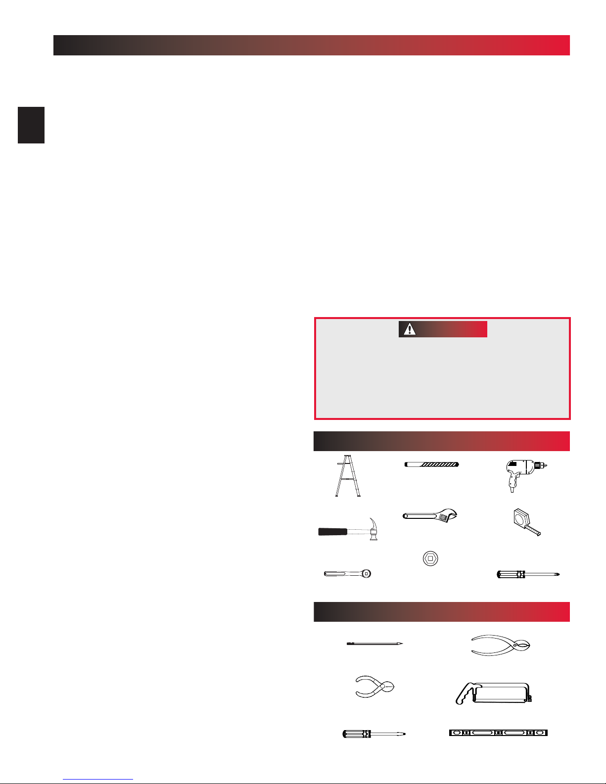
TOOLS REQUIRED
Drill Bit
Stepladder
)
. Contact Customer
5/32"
Drill
Is your garage door made of light-weight
steel, aluminum, fiberglass, or glass
panels
4
added to these type doors. If this is the case,
please contact the door distributor or manufacturer
so that they can furnish you with a “bracing kit.”
You need a 110-120 Volt power supply
available
standard electrical outlet, is one available?
5
The outlet should be no more than 3 feet from
the power head once it is mounted.
To avoid damage to your door and/or
operator, make sure you disable any door
locks prior to installing your operator
6
? Additional support bracing must be
. If you plan to plug the unit into a
Wrench
Hammer
3/8", 7/16", 1/2"
Ratchet
ADDITIONAL TOOLS
Pencil
Wire Strippers
.
Straight Blade Screwdriver
and 9/16" Sockets
YOU MAY NEED
Carpenter’s Level
Tape Measure
Phillips Screwdriver
Pliers
Hack Saw
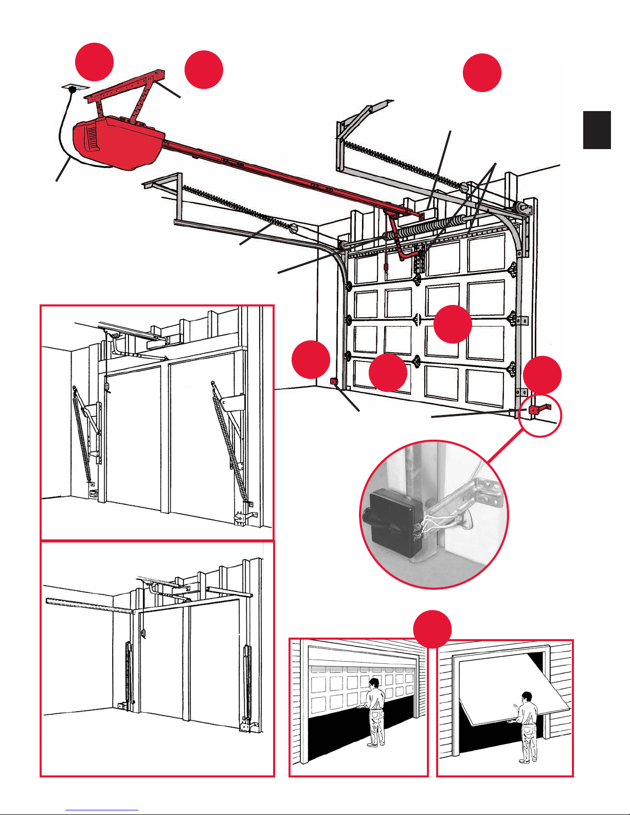
TYPICAL SECTIONAL DOOR INSTALLATION
5
36” POWER CORD
TO
120V GROUNDED
OUTLET
1
TYPICAL
SUPPORT
BRACKET
EXTENSION SPRING
OR
TORSION SPRING
3
6
2
ADDED
HEADER BRACKET
MOUNTING BOARD
3
BRACES
4
3
TYPICAL (TRACKLESS)
1-PIECE DOOR INSTALLATION
SAFE-T-BEAM
®
7
TYPICAL (TRACK GUIDED)
1-PIECE DOOR INSTALLATION
SECTIONAL DOOR
ONE-PIECE DOOR
3
DEF
1
2
456
7
8
9
0
GHI
JKL
MNO
P
QRS
TUV
WXYZ
9
V
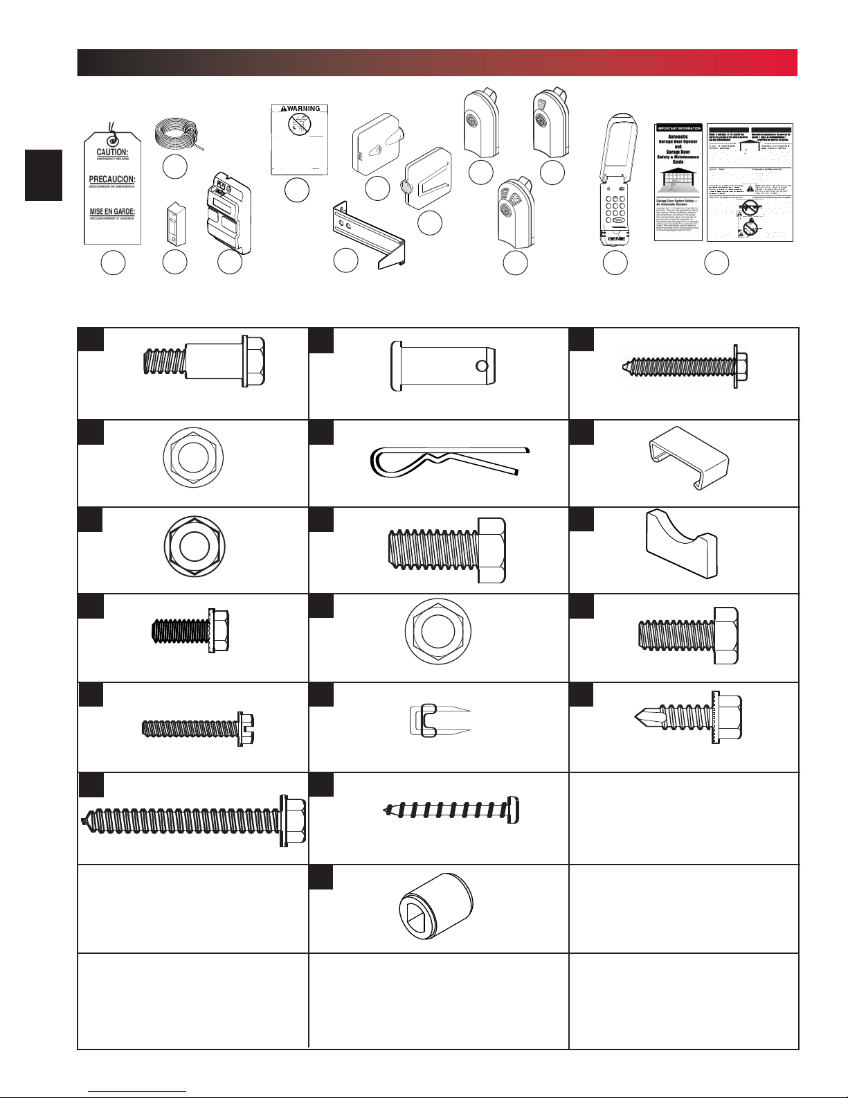
PARTS IDENTIFICATION
FOR HELP-1.800.929.3667 OR OVERHEADDOOR.COM
4
25
39
40
NOTE: Accessories vary by Model
42
45
.
FASTENERS - Shown Full Size. See Parts List for description.
37
2
1/4"-20 Shoulder Bolt
8
1/4"-20 Nut
11
32
33
35
43
44
Clevis Pin
Cotter Pin
48
49
51
50
47
#10-16 x 1-1/4" Phillips Hex Head Screw
53
Wire Clip
54
52
16
21
30
5/16"-18 Nut
1/4"-20 x 5/8" Bolt
#8-32 x 1" Screw
1/4" x 2" Lag Screw
36
38
41
46
3/8"-16 x 7/8" Bolt
3/8"-16 Nut
Insulated Staple
#6 x 1-1/4” Pan Head Screw
Coupler
Rubber Bumper
55
5/16"-18 x 3/4" Bolt
56
1/4"-20 x 3/4" Self-Drilling Screw
D
OOR
DOOR
D
OOR
DOOR
12
22
24
31
35
33
36
34
32
32
28
11
26
30
15
16
53
2
19
18
1
30
2
1
54
46
56
3
8
23
8
33
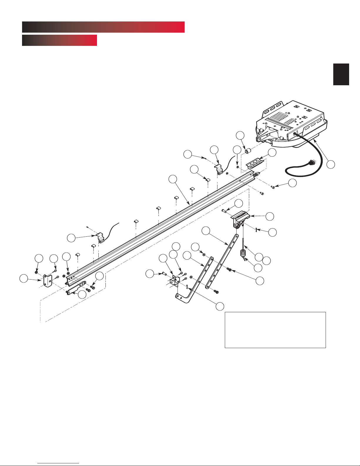
1-PIECE BOOM HARDWARE EXPLODED VIEW
“PRO” ONLY
[3]
NOTE: The Operator will not
function unless the Safe-T-Beam
System is installed and the
Force Controls are properly set.
®
5
Assembly for 10' or 12' door includes:
1. Special “Close” Limit Switch with longer
wires.
2. 96" Emergency Release Cord (yellow)
3. Rail Support Kit
PARTS LIST
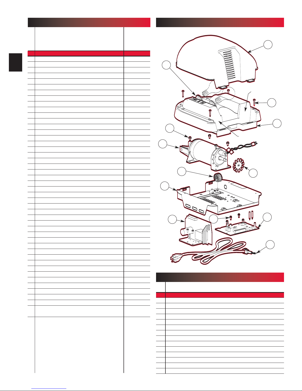
POWER HEAD EXPLODED VIEW
[1]
Item Part Name Parts Required
1 Power Head Assembly (main carton) 1
6
2 1/4"-20 Hex Head Shoulder Bolt (blue bag) 2
3 Boom Assembly (1 piece)(packaged separately) 1
8 1/4"-20 Hex Serrated Flange Nut (blue bag) 4
11 5/16"-18 Hex Serrated Flange Nut (blue & orange bag)
12 Carriage Assembly (main carton) 1
15 Boom Strap (blue bag) 1
16 1/4"-20 Hex Head Bolt (blue bag) 2
18 Open Limit Switch Assembly (White)(green bag) 1
19 Close Limit Switch Assembly (Brown) (green bag) 1
21 No.8-32 x 1" Hex Head Screw (green bag) 2
22 Emergency Release Cord (green bag) 1
23 Emergency Release Cord (long)(yellow)
24 Emergency Release Knob (green bag) 1
25 Emergency Release Tag (green bag) 1
26 Header Bracket (orange bag) 1
28 Door Bracket (orange bag) 1
30 1/4" x 2" Lag Screw (orange bag)
31 Straight Door Arm (main carton) 1
32 Clevis Pin (yellow bag) 2
33 Cotter Pin (yellow bag) 2
34 Curved Door Arm (main carton) 1
35 3/8" x 7/8" Hex Head Bolt (yellow bag) 2
36 3/8" Hex Serrated Flange Nut (yellow bag) 2
37 Wire (main carton)
38 Insulated Staple (red bag)
39 Wall Button (red bag)
40 Wall Console (main carton)
41 #6 x 1-1/4" Pan Head Screw (red bag) 4
42 Entrapment WARNING Label (manual) 1
43 Safe-T-Beam (STB) Sensor (Green LED)(main carton) 1
44 Safe-T-Beam (STB) Source (Red LED)(main carton) 1
45 Safe-T-Beam (STB) Bracket (yellow bag) 2
46 Coupler (blue bag) 1
47 No.10-16x1 1/4" Phillips Hex Head Screw (yellow bag) 4
48 Single Button Remote Control (main carton)
49 Multi-Button Remote Control (main carton)
50 Wireless Keypad (main carton)
51 2-Button Remote Control (main carton)
52 Safety & Maintenance Guide (manual) 1
53 Wire Clip (green bag)
54 Carriage Stop (blue bag) 1
55 5/16"-18x 3/4" HexHead Bolt (orange bag)
56 1/4-20 x 3/4" Self-drilling Screw (orange bag) 3
57 Mounting Straps (main carton)
varies/model
10' & 12' only
varies/model
≈
95ft
≈
30
varies/model
varies/model
varies/model
varies/model
varies/model
varies/model
varies/model
varies/model
varies/model
1C
1K
1D
1N
1B
1G
1M
POWER HEAD PARTS LIST
Item Part Name
1 Power Head Assembly
1A Lens (By Series/Model)
1B Top Plate Assembly
1C Light Socket (2)
1D Motor Assembly
1E Cover
1F Opto Wheel
1G Motor Drive Board
1H Controller Board
1K No. 10-24 x 3/8”Hex Head
1L No. 8-32 x 1” Phillips Screw
1M No. 8-32 x 3/8”Slotted Hex Head Screw
1N Toroid
1P Power Cord
1A
MODEL
NUMBER
1L
1E
SERIAL NUMBER
1F
1H
1P
SAFETY INFORMATION OPERATOR INSTALLATION
OVERVIEW OF
POTENTIAL HAZARDS
Garage Doors are large, heavy objects that move with the help of springs
under high tension and electric motors. Since moving objects, springs under
tension, and electric motors can cause injuries, your safety and the safety of
others depend on you reading the information in this manual. If you have
questions or do not understand the information presented, call your nearest
service representative.
In this Section and those that follow, the words Danger, Warning, and
Caution are used to emphasize important safety information. The word:
DANGER means that severe injury or death will result from failure to
follow instructions.
WARNING means that severe injury or death can result from failure to
follow instructions.
CAUTION means that property damage or injury can result from failure to
follow instructions.
The word NOTE is used to indicate important steps to be followed or
important considerations.
POTENTIAL
HAZARD
MOVING
DOOR
ELECTRICAL
SHOCK
HIGH
SPRING
TENSION
EFFECT PREVENTION
Keep people clear of opening while door is
WARNING:
Can Cause
Serious Injury
or Death
WARNING:
Can Cause
Serious Injury
or Death
WARNING:
Can Cause
Serious Injury
or Death
moving.
Do Not allow children to play with the door
operator.
Do Not operate a door that jams o r one t hat
has a broken spring.
Turn off power before removing operator
cover.
When replacing cover, make sure wires are
not pinched or near moving parts.
Operator must be properly grounded.
Do Not try to remove, repair or adjust
springs or anything to which door spring
parts are fastened, such as, wood blocks,
steel brackets, cables or other like items.
Repairs and adjustments must be made by
a trained service person using proper tools
and instructions.
IMPORTANT
INSTALLATION
INSTRUCTIONS
WARNING
WARNING
:
:
To reduce the risk of
severe injury or death:
1. READ AND FOLLOW ALL SAFETY, INSTALLATION AND
OPERATION INSTRUCTIONS. If you have any questions or
do not understand an instruction, call your service
representative.
2. Do Not install operator on an improperly balanced door. An
improperly balanced door could cause severe injury.Repairs
and adjustments to cables, spring assembly, and other
hardware must be made by a trained service person using
proper tools and instructions.
3. Remove all ropes,and disable all locks connected to the
door before installing operator.
4. Install door operator 7 feet or more above the floor. Mount
the emergency release knob 6 feet above the floor.
5. Do Not connect the operator to the source of power until
instructed to do so.
6. Locate the control button:
• Within sight of door.
• At a minimum height of 5 feet,so small children cannot
reach it.
• Away from all moving parts of the door.
7. Install the entrapment WARNING label next to the wall
button or console. Install the emergency release tag on, or
next to, the emergency release
8. The operator must reverse when the door contacts a 1-1/2
inch high object on the floor at the center of the doorway.
This is about the size of a 2" x 4" board laid flat.
7
SAFETY FEATURES
(
varies by model
Safe-T-Beam®(STB) Non-Contact Reversing System
Places an invisible beam across door opening, that reverses the door during down travel to the fully open
position if anything passes through beam.
Safe-T-Reverse
®
Contact Reversing System
Automatically stops and reverses a closing door within 2 seconds of contact with an object.
Safe-T-Stop
®
Timed Reversed System
Automatically opens a closing door, if door does not close within 30 seconds.
Force Guard
®
Control
Used to set the force required for opening and closing door. For maximum safety, set the minimum force
required to fully open and close door.
Automatic Lighting System
T
wo light bulbs up to 60 Watts max. each, are used for safer entries and exits. The light turns on when door is
activated and automatically turns of
f 4.5 minutes later
Manual Emergency Release
Allows the garage door to be opened or closed manually for emergencies or maintenance.
)
.
...
OPERATOR ASSEMBL Y & INSTALLATION
1
Record your Model Number and Serial
Number now on page 11 in the center of
this manual.
OPERATOR ASSEMBLY
FOR HELP-1.800.929.3667 OR OVERHEADDOOR.COM
8
8
OPEN BLUE PARTS BAG
NOTE: 3 piece operator assembly is for doors up
to 7 feet 6 inches high. An extension kit for an 8 feet
high door is available.
Assemble on a clean, flat surface.
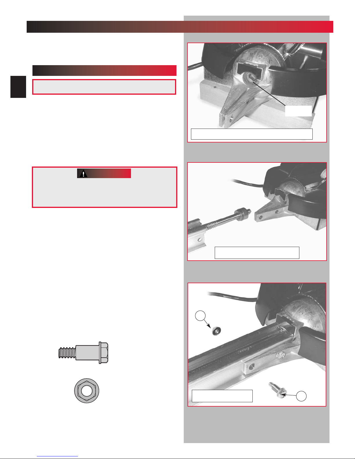
1. Install coupler [46] (Fig. 1-1).
• Line up and slide on motor shaft.
CAUTION
Drive screw and boom liner can slide out
of boom sections. Keep boom sections
level until operator is fully assembled.
.
2. Connect boom to power head. Either 1-piece
boom or first section of 3-piece boom
(
Fig. 1-2).
•
Insure arrow on boom points away from power
head. (Fig 1-4 on page 9.)
•
Push drive screw out about 5 inches.
• Line up and slide drive screw into coupler.
Slide boom into bracket and line up holes with
•
those on power head (Fig. 1-3).
– Connect with bolts [2] and nuts [8].
Coupler
Fig. 1-1 Install rubber bumper and coupler
Fig. 1-2 Push drive screw out
[2]
1/4"-20 Hex Head Bolt
[8]
1/4"-20 Hex Flange Nut
8
Fig. 1-3 Attach boom
2
CAUTION
Drive screw section and boom liner can slide
out of boom sections. Keep boom sections
level until operator is fully assembled
3. On 1 piece boom assembly go to step 11.
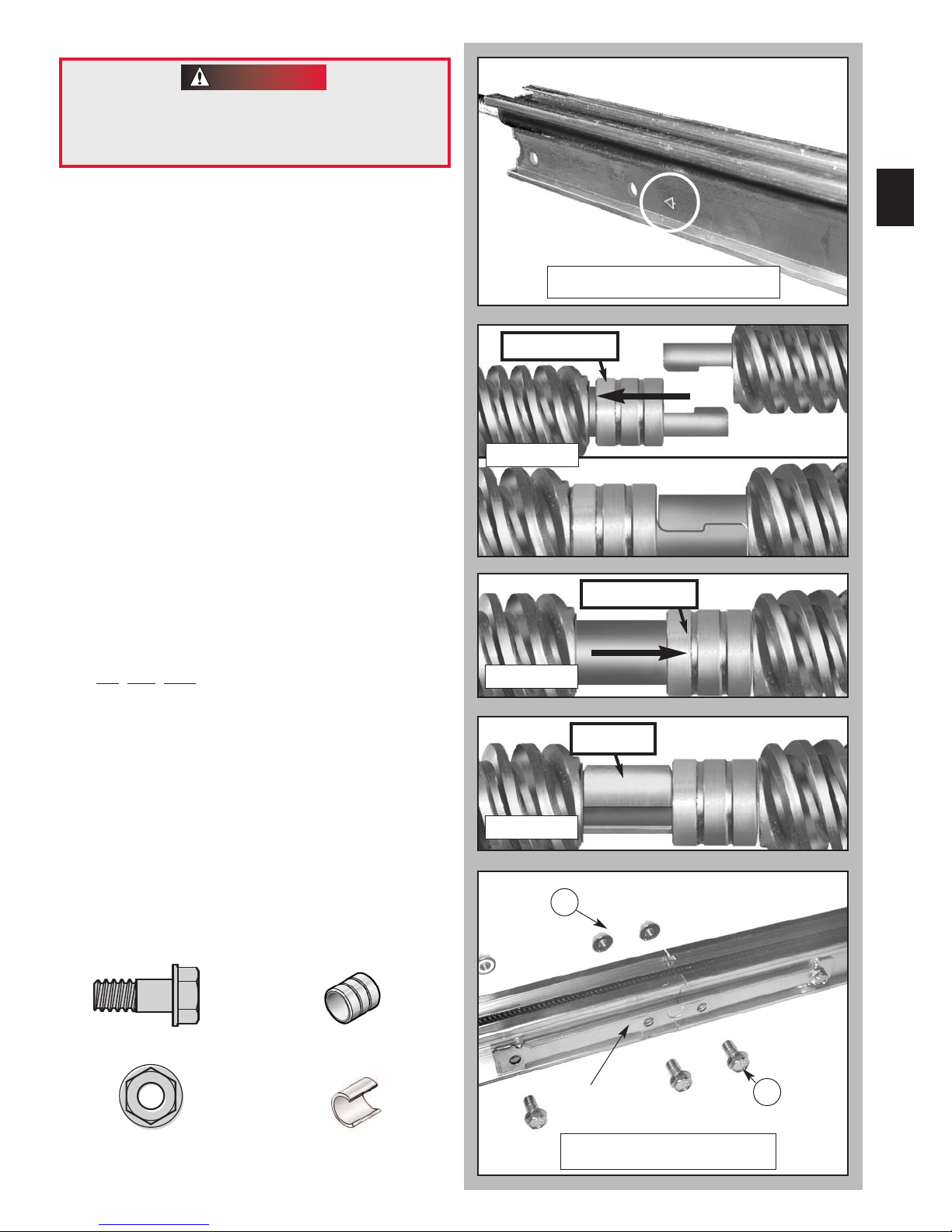
4. Arrange arrows on boom sections (Fig. 1-4).
• Point arrows in same direction
power head.
5. Attach middle boom section to first
boom section.
•
Push middle drive screw out about 2 inches
toward the power head.
•
Slide collar [13] over the middle boom hook
(Fig.1-5).
• Turn screw by hand to align coupler hooks
between first and middle boom sections.
• Latch the two hooks together and
slide the collar over them (Fig. 1-6).
•
Snap clip [14] next to collar (Fig. 1-7).
6.
Attach boom clamps at the middle boom to
first boom joint (Fig. 1-8).
•
Slide the middle boom section against the first
boom section.
Place a boom clamp on each side of the boom
•
at the joint and line up the holes with those in
the boom.
• Fin
ger tighten boom clamps with bolts [10] and
nuts [11].
away
from
9
Fig. 1-4 Arrange arrows
slide collar
Fig. 1-5
slide collar
Fig. 1-6
7. Attach end boom section to middle boom
section to first boom section (Step 6).
8. Attach boom clamps at the end boom to
middle boom joint (Fig. 1-8).
•
Repeat procedure used to attach middle boom
section to first boom section (Step 7).
NOTE: If installing a 3-piece boom assembly on
an eight foot high door refer to the instruction
sheet included with the optional boom extension
at this point.
[
]
[
]
10
5/16"-18 Hex Head Shoulder Bolt
[11]
5/16"-18 Hex Head Flange Nut
Collar
Retaining Clip
13
[
14
]
Fig. 1-7
clip
11
Clamp
het
Fig. 1-8 Attach rail clamps
10
10
10
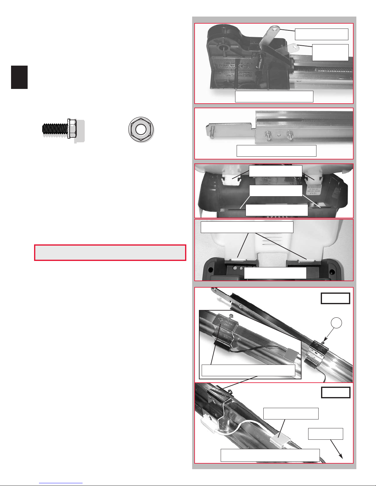
9. Install carriage and carriage stop (Fig. 1-9).
• Slide carriage stop into railand along the length
of the rail to the power head.
• Point arrow on side of carriage toward door.
• Place carriage lever in release position.
• Slide into carriage slot of boom assembly.
NOTE: Carriage release lever will be facing
power head.
10. Attach boom strap (Fig. 1-10).
• Connect to end boom section with bolts
[16] and nuts [8].
Release position
Engaged
position
Fig. 1-9 Install carriage
[
]
16
1/4"-20 Hex Head Bolt
11. Tighten all nuts and bolts.
NOTE: Tighten nuts and bolts on boom so that
they grip metal snuggly. Do Not Over-Tighten.
12. Install lens cover (Fig. 1-11).
• Align hinge tabs with slots on motor cover
(Fig. 11A).
•
Move antenna outside lens and out of way
• Push hinges into slots on cover until
they snap into place (Fig. 11B).
•
Swing lens cover closed and snap into place.
1/4"-20 Serrated Hex Nut
[8]
.
OPEN GREEN PARTS BAG
13. Place limit switches (
•
urn unit right side up.
T
• Uncoil limit switch wires.
• Place switches on boom with arrows pointing
toward boom strap.
– Place CLOSE limit switch (brown wire) 12
from boom strap.
– Finger tighten the hold-down screw [21].
– Lay out the wire in the channel on top of the
boom, using wire clips [53] to hold it in place
as you go toward the power head.
– Save one clip for the OPEN switch.
– Place OPEN limit switch (white wire) 12
from power head. (Place over brown wire.)
– Finger tighten the hold-down screw.
– Lay out the wire in the channel on top of the
boom, using the last wire clip to hold both
limit switch wires in place.
Fig. 1-12).
"
"
Fig. 1-10 Attach boom strap
Hinge tabs
Slots
Fig. 1-11A Install lens
Push in until they catch
Fig. 1-11B Install lens
CLOSE
21
Arrow points toward boom strap
OPEN
NOTE:Do not over-tighten screw [21] on limit
switch brackets.
• Limit switch adjustments will be made later.
Last wire clip [53]
power head
Fig. 1-12 Limit switch placement
 Loading...