

Overhead door Legacy 800 2026 User Manual

2026
®
Legacy
800
Chain and Belt Openers
• CodeDodger®remotecontrol
fortheultimateinsafety!
®
• Safe-T-Beam
beinstalledtoclosedoor
• Homelink
compatible
systemmust
®
andCar2U®
• 2-bulblightsystem
• Wallconsole
• Foruseonlywithsectional
doors
• Easyprogramming
For answers and assistance
1.800.929.3667
or visit
www.OverheadDoor.com
Installer: Leave this manual with homeowner.
Legacy
Save this manual for future reference.
© 2009 Overhead Door Corporation. Overhead Door, Legacy, and the Ribbon logo are registered trademarks of Overhead
Door Corporation. All other trademarks are the property of their rightful owners. Consistent with our policy of continuing
product improvements, we reserve the right to change product specifications without notice or obligations. R900-785
Homelink® is a registered trademark of Johnson Controls Technology Company.
®
is a registered trademark of Lear Corporation.
Car2U
®
800 Model 2026
GARAGEDOOROPENERS
PN# 37027500123 2/26/2010 REV.1
SAFETY INFORMATION
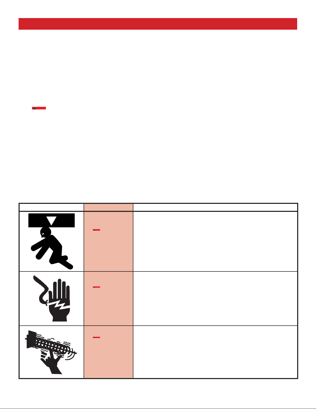
OVERVIEW OF POTENTIAL HAZARDS
READ THIS SAFETY INFORMATION
CONVENTIONS USED IN THESE INSTRUCTIONS
Overhead doors are large, heavy objects that move with the help of springs under high tension and electric motors. Since moving
objects, springs under tension, and electric motors can cause injuries, your safety and the safety of others depend on you reading
the information in this manual. If you have questions or do not understand the information presented, call your nearest trained
door system technician.
The following safety alert symbol and signal words are used throughout this manual to call attention to and identify different
levels of hazard and special instructions.
This is the safety alert symbol. This symbol alerts you to potential hazards that can kill or hurt you and others.
All safety messages will follow the safety alert symbol and the word "DANGER", "WARNING", or "CAUTION"
DANGER indicates an imminently hazardous situation which, if NOT avoided, will result in death or serious injury.
WARNING indicates a potentially hazardous situation which, if NOT avoided, could result in death or serious injury.
CAUTION indicates a potentially hazardous situation which, if NOT avoided, may result in injury or property damage.
The word NOTE is used to indicate important steps to be followed or important considerations.
CAUTION
IMPORTANT SAFETY INSTRUCTIONS
READ AND FOLLOW ALL INSTRUCTIONS
SAVE THESE INSTRUCTIONS
Potential Hazard Effect Prevention
CAUTION
WARNING
Could result in Death
or Serious Injury
CAUTION
WARNING
Could result in Death
or Serious Injury
Keep people clear of opening while Door is moving.
Do NOT allow children to play with the Door Operator.
Do NOT operate a Door that jams or one that has a broken spring.
Turn OFF power before removing operator cover.
When replacing cover, make sure wires are NOT pinched or near moving
parts.
Operator must be fully grounded.
CAUTION
WARNING
Could result in Death
or Serious Injury
2
©2009 Overhead Door Corporation Part Number 37027500123 02/26/2010 REV. 1
Do NOT try to remove, install, repair or adjust springs or anything to which
door spring parts are fastened, such as, wood blocks, steel brackets, cables
or other like items.
Installations, repairs and adjustments must be done by a trained door
system technician using proper tools and instructions.

OPENER FEATURES
C
ODEDODGER
An electronic access code system that enhances the security of the door opener by continuously changing the access code each
time the remote control is used. The door opener responds to each new code only once. An access code copied from a working
system and tried again will not control the door opener.
®
Access Security System
Lighted Wall Button*
Operates door opener from inside garage. (Refer to section 3)
and Car2U® compatible.
Follow the Homelink® or Car2U® instructions in your car owner’s
manual.
SAFETY FEATURES
Safe-T-Beam
Puts an invisible beam across the door opening. The door stops
and reverses to the full open position if anything passes through
the beam. Red or green LED indicator lights on the power head
provide a self diagnostic code if an operational problem exists.
(Refer to Section 10)
®
Non-Contact Reversing System**
Safe-T-Reverse® Contact Reversing System
Automatically stops and reverses a closing door within 2 seconds
of contact with an object. (Refer to Section 6)
Safe-T-Stop® Timed Reversed System
Automatically opens a closing door if it fails to close completely
within 30 seconds.
Watch Dog™ Monitoring System
Monitors the Safe-T-Beam®** system to ensure proper functionality
and will automatically stop and reverse a closing door if a problem
is detected.
Automatic Lighting System
Two bulb lighting supplies up to 120 watts of light for safer
evening exits and entries. Turns ON when door is activated and
automatically turns OFF 3 minutes later.
Manual Emergency Release
Manually releases door from door opener. Use during a power
failure or other emergency to allow manual opening and closing of
door. (Refer to Section 6)
TABLE OF CONTENTS
SECTION ......................................................................................PAG E
SAFETY INFORMATION .................................................................2
OPENER FEATURES .......................................................................... 3
SAFETY FEATURES ..........................................................................3
PRE-INSTALLATION CHECK LIST ...........................................4-5
RECOMMENDED TOOLS ...............................................................6
PARTS IDENTIFICATION ............................................................6-7
KEY ILLUSTRATIONS ......................................................................8
SAFETY INSTALLATION INFORMATION .................................9
INSTALLATION
1 OPENER ASSEMBLY ...........................................................9-10
2 INSTALLATION .................................................................11-13
3 WALL CONTROL INSTALLATION ..................................14-15
4 SAFE-T-BEAM® SYSTEM INSTALLATION ..................... 16-17
5 CONNECTING TO POWER ................................................... 18
ADJUSTMENTS
6 LIMIT SWITCHES & FORCE ADJUSTMENT ................. 19-20
CONTACT REVERSE TEST ...................................................... 20
7 PROGRAMMING REMOTE CONTROLS ............................. 21
8 BATTERY/VISOR CLIP INSTALLATION ............................... 22
9 LIGHT BULB AND LENS INSTALLATION ............................ 22
SAFETY INSTRUCTIONS ............................................................. 23
MAINTENANCE & TROUBLESHOOTING
10 ROUTINE MONTHLY MAINTENANCE ............................... 23
WIRING DIAGRAM ................................................................ 24
TROUBLESHOOTING GUIDE - OPENER ............................ 25
TROUBLESHOOTING GUIDE - POWER HEAD LED ........ 26
TRANSMITTER COMPLIANCE STATEMENT ....................... 27
WARRANTY .....................................................................................28
*OPENER MUST BE INSTALLED WITH THE INCLUDED
WALL CONTROL.
**SAFE-T-BEAM® SAFETY REVERSE SYSTEM MUST BE
INSTALLED TO CLOSE DOOR.
©2009 Overhead Door Corporation Part Number 37027500123 02/26/2010 REV. 1
3
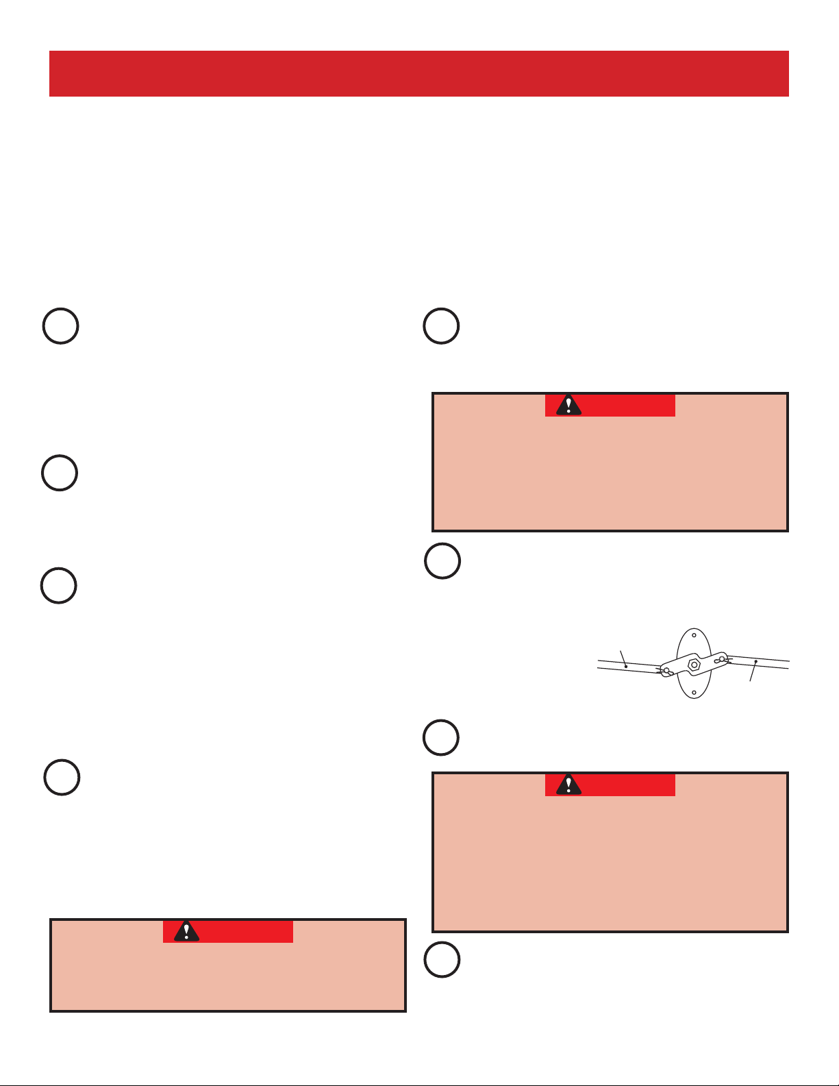
PRE-INSTALLATION CHECK LIST ............................................. FOR HELP-1.800.929.3667 OR WWW.OVERHEADDOOR.COM
Things to consider if you are planning to "Do-it-yourself."
This opener is designed for use with SECTIONAL doors only.
In many cases you will be replacing an existing door opener with a new one, however, if this will be the first opener
installed there are some pre-installation issues which need to be addressed. They are as follows:
The Overhead Door Corporation recommends that you read and fully understand all information and
instructions contained herein before choosing a "Do-it-yourself" installation. Any questions should be
directed to Overhead Door Corporation or an authorized Overhead Door Dealer.
(The issue numbers below refer to the circled numbers in the illustrations on page 5.)
Check your ceiling where the power head of
1
your new unit will be mounted. Plan how you
will be mounting the power head. It is possible that
ceiling joists may not be in the position needed with
respect to the garage door opener. It may be necessary
to add an additional bracket and fasteners (not included
with your new door opener kit). (Refer to Section 2)
Check the wall directly above the garage
2
door. The door opener’s header bracket must be
securely fastened to this wall. Insure that the structure
will provide a strong mounting location.
(Refer to Section 2)
Check to see if the mounting location for the
3
Safe-T-Beam® System is clear from obstruction
and has a wood surface available for attaching the
mounting brackets. The brackets may be attached
to concrete if necessary but extra tools and special
fasteners (not supplied) will be required.
(Refer to Section 4 and 5)
NOTE: Mounting brackets must be installed within
code specifications.
You need a properly grounded 110-120 Volt
5
power supply available. The outlet should be
no more than 3 feet from the power head once it is
mounted. (Refer to Section 5)
WARNING
DO NOT USE AN EXTENSION CORD!
DO NOT USE A PORTABLE GENERATOR! This
product is designed to operate on standard
house current.
DO NOT USE ALTERNATE POWER SUPPLIES.
To avoid damage to your door and/or opener,
6
make sure you disable and/or remove any door
locks, ropes, and/or cables (NOT door lift cables) prior
to installing your opener. (Refer to Section 1)
Remove
Remove
Insure that your door is properly balanced and
7
moving freely. (Refer to Section 10)
Is your sectional garage door made of
4
aluminum, light-weight steel, fiberglass or
glass panels? Additional support bracing must be
added to these type doors. If this is the case, please
contact the door manufacturer or authorized dealer so
that they can furnish you with a "bracing kit."
(Refer to Section 2)
WARNING
TO REDUCE THE RISK OF INJURY TO PERSONS OR
DAMAGE TO PROPERTY - USE THIS OPENER ONLY
WITH SECTIONAL DOORS.
4
©2009 Overhead Door Corporation Part Number 37027500123 02/26/2010 REV. 1
WARNING
If your door jams, binds, is improperly
balanced or has a broken spring, have it
repaired or adjusted by a trained door system
technician. Door springs, cables, pulleys,
brackets and associated hardware are under
extreme tension and can cause serious injury
or death.
(NOT SHOWN) If your garage does not have a
8
separate entry door, you should consider an
emergency release kit (GER-2) for installation on your
garage door.
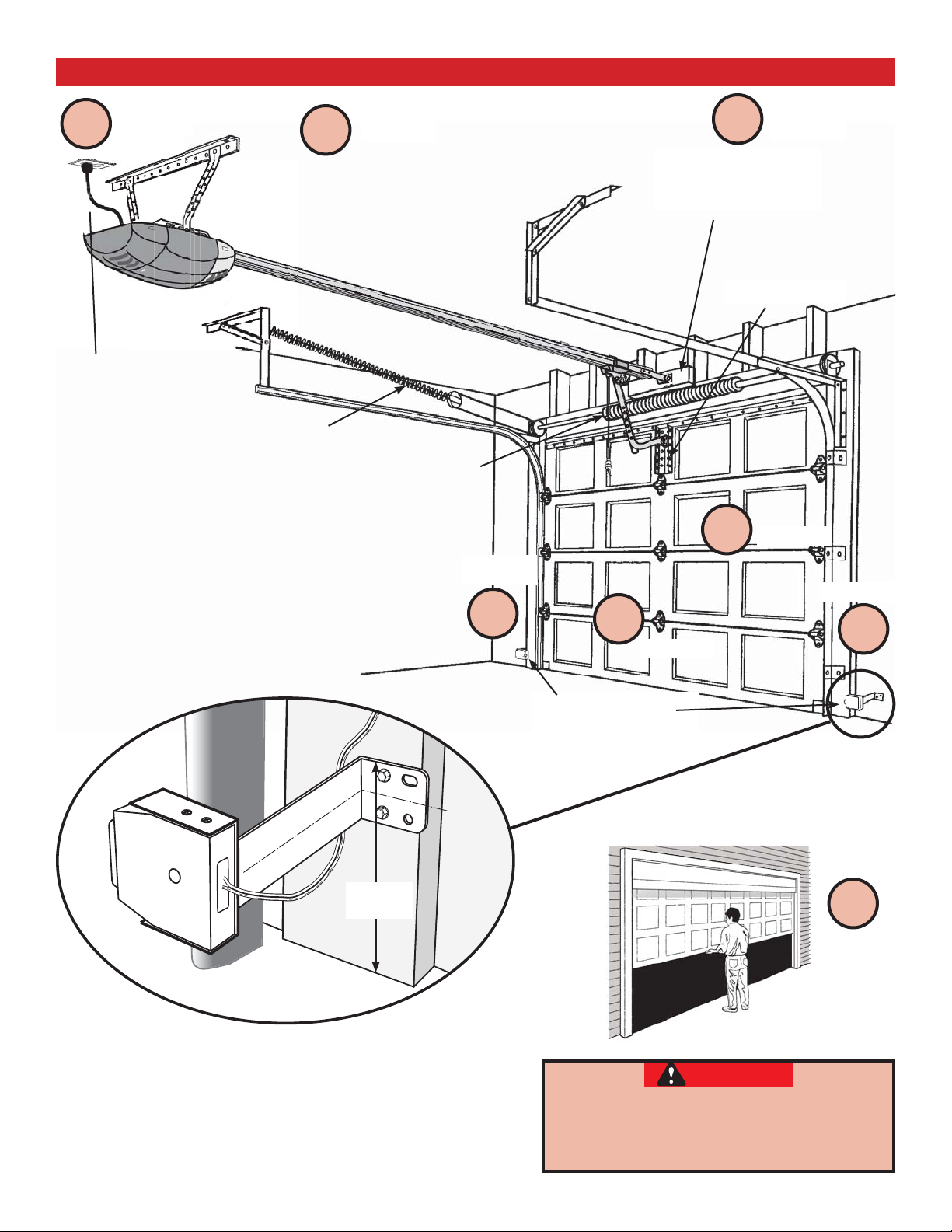
TYPICAL SECTIONAL DOOR INSTALLATION ................ FOR HELP-1.800.929.3667 OR WWW.OVERHEADDOOR.COM
5
TYPICAL SUPPORT
(NOT PROVIDED)
POWER CORD
(APPROX. 45 IN.)
TO 120V GROUNDED
OUTLET
EXTENSION SPRING
NOTE: This opener is designed for
use with SECTIONAL doors only.
1
BRACKET
Pg. 13Pg. 19
OR
TORSION SPRING
Pg. 17-18
Pg. 12-13
2
ADDED
HEADER BRACKET
MOUNTING BOARD
BRACING
Pg. 14
4
Pg. 17-18
MAX. 6"
MIN. 5"
3
6
Pg. 11
SAFE-T-BEAM®
SENSORS
3
7
Pg. 25
SECTIONAL DOOR
WARNING
To reduce the risk of injury to persons or
damage to property - Use this opener only
with sectional doors.
©2009 Overhead Door Corporation Part Number 37027500123 02/26/2010 REV. 1
5
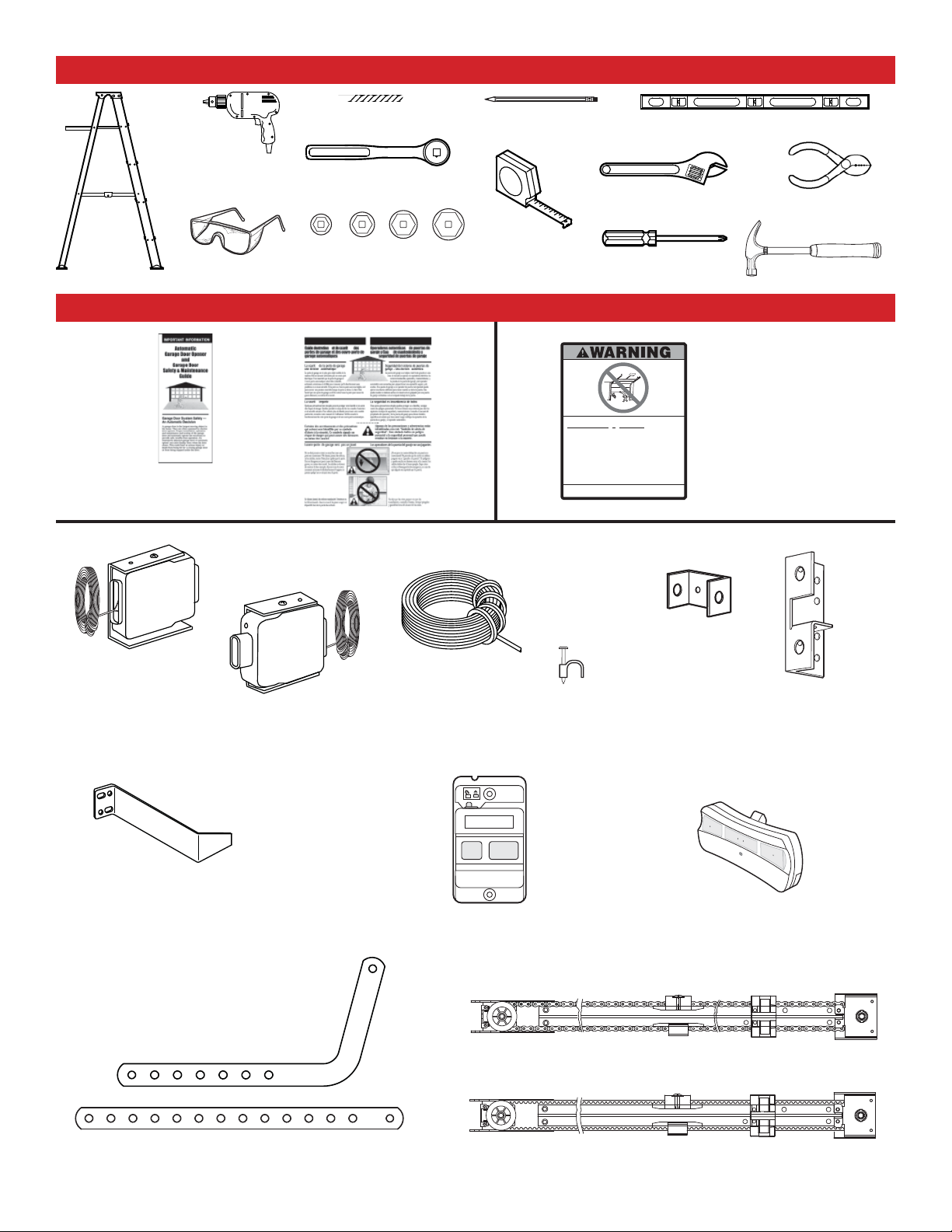
RECOMMENDED TOOLS FOR HELP-1.800.929.3667 OR WWW.OVERHEADDOOR.COM
3/16" Drill Bit
Drill
Ratchet
1/4", 7/16", 3/8" and
Step ladder
Safety Glasses
1/2" Sockets
PARTS IDENTIFICATION - Not Shown Full Size
Safety Brochures
Pencil
Tape measure
Child canbe pinned under automatic garage
Death or serious injury can result.
Adjustable wrench
Phillips screwdriver
Never let child walk or run under moving door.
•
Never let child use door opener controls.
•
Always keep moving door in sight.
•
If person is pinned, push control button or use
•
emergency release.
Test door opener monthly:
•
Refer to your owner'’smanual.
1
Place 1
/2-inch object (or 2x4 laid flat) on floor.
If door fails to reverse on contact, adjust opener.
If opener still fails to reverse door, repair or replace opener.
Do not remove or paint over this label.
Mount wall control out of child's reach
Place next to wall control.
(at least 5 feet above floor).
Carpenter’s level
Wire strippers
Hammer
door.
.
Entrapment Warning
Label
©1999
Safe-T-Beam®
Source
with wire
(Red LED)
Safe-T-Beam®
Source/Sensor Bracket
Safe-T-Beam®
Sensor
with wire
(Green LED)
Wire
Wall Control,
Insulated Staple
Pro Rail (Chain) Section
Header Bracket
Door
Bracket
Three-button
Remote Control
Door Arm
6
©2009 Overhead Door Corporation Part Number 37027500123 02/26/2010 REV. 1
Pro Rail (Belt) Section
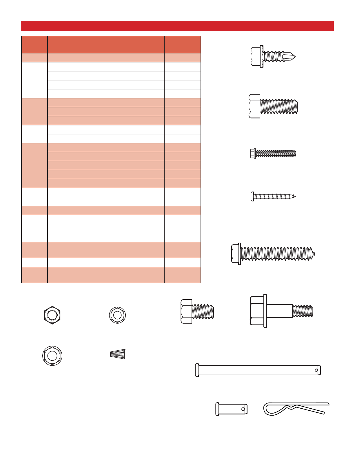
FASTENERS - Shown Full size (See Parts List below for full description.)
BAG NO. DESCRIPTION QUANTITY
1 BOLT – 5/16-18 x 1/2" 3
CLEVIS PIN, LONG – 5/16" x 3" 1
COTTER PIN 1
2
HEADER BRACKET 1
LAG SCREW – 5/16" x 2" 2
HEX BOLT – 5/16-18 x 3/4" 5
3
HEX FLANGE NUT – 5/16-18 5
LAG SCREW – 5/16" x 2" 2
SELF DRILLING SCREW – 1/4"-20 x 3/4" 3
4
DOOR BRACKET 1
HEX BOLT – 5/16-18 x 3/4" 3
SELF LOCKING NUT – 5/16-18 1
5
HEX FLANGE NUT – 5/16-18 2
CLEVIS PIN – 5/16" x 3/4" 1
COTTER PIN 1
WALL CONTROL BUTTON ASSEMBLY 1
6
PAN HEAD PHILLIPS SCREW – #4-24 x 1" 2
7 13 MM INSULATED STAPLE 30
Safe-T-Beam
8
PHILLIPS HEX SCREW – #10-16 x 1- 1/4" 4
WIRE NUT (GREY) 4
NO
NUMBER
NO BAG Safe-T-Beam® SOURCE/SENSOR & WIRE SET 1
NO
NUMBER
REMOTE WITH BATTERY 1
LIGHT COVER - WHITE 2
®
SOURCE/SENSOR BRACKET 2
#10-16 x 1-1/4" Phillips Hex Screw
Self-drilling Screw
1/4-20 x 3/4"
Hex Bolt - 5/16 -18 x 3/4"
#4-24 x 1" Pan Head
Phillips Screw
Lag screw - 5/16" x 2"
Self Locking Nut
- 5/16 -18
Hex Flange Nut
- 5/16 -18
Hex Flange Nut
- 1/4"-20
Wire Nut
Hex Bolt - 5/16 -18 x 1/2"
MISSING ANY PARTS? Please call toll free - 1.800.929.3667
DO NOT RETURN TO POINT OF PURCHASE.
IMPORTANT! - Information needed when calling
• Model number - (located on packaging)
• Store, city, state, and date of purchase
©2009 Overhead Door Corporation Part Number 37027500123 02/26/2010 REV. 1
Clevis pin, long
Clevis pin
5/16" x 3/4"
Shoulder Bolt
- 5/16 -18 x 1"
5/16" x 3"
Cotter pin
7

1-PIECE RAIL ASSEMBLED VIEW .............................FOR HELP-1.800.929.3667 OR WWW.OVERHEADDOOR.COM
T
Rail with belt
Belt
Carriage Slide
Belt Clamp
Bracket
Header
& Cotter Pin
Clevis Pin, Long
Chain
ensioner
ser
Repairs or
Can Cause Serious Injury or Death
vic
HIGH S
e p
erson using prope
adjus
tm
PRING TENSION
e
nts
mu
st
r
to
be m
ols and i
ade
by a trai
nstr
uct
ions
ned
d
So
m
b
o
ra
an
o
m
in
r d
cing
e
u
st
NOTE
d
fac
istr
r
uc
o
.
tur
o
C
ib
tion
rs n
on
u
e
t
r
ta
o
s
e
fo
.
r o
c
e
t
d
r
r
CHAIN
Rail with chain
BELT
Release
Knob
Carriage Slide
Power Cord
Power Head
8
©2009 Overhead Door Corporation Part Number 37027500123 02/26/2010 REV. 1
IMPORTANT INSTALLATION INSTRUCTIONS
CAUTION
WARNING: To reduce the risk of severe injury or death:
1. READ AND FOLLOW ALL SAFETY, INSTALLATION
AND OPERATION INSTRUCTIONS. (If you have
questions or do not understand an instruction,
call the Overhead Door Corporation or an
authorized Overhead Door Dealer.)
2. Install only on a properly balanced sectional
garage door. An improperly balanced door could
cause severe injury. Have a trained door system
technician make repairs or adjustments to cables,
spring assemblies, and other hardware before
installing the opener.
3. Remove all ropes and remove or make
inoperative all locks connected to the garage
door before installing opener.
4. Where possible, install the door opener 7 feet
5. Do NOT connect the opener to source of power
until instructed to do so.
6. Locate the Wall Control:
• Within sight of door,
• At minimum height of 5 feet so small
children are not able to reach it, and
• Away from all moving parts of the door.
7. Install the Entrapment WARNING Label next to
the Wall Control in a prominent location. Install
the Emergency Release Tag on or next to the
emergency release.
8. After installing the opener, the door must
reverse within 2 seconds when it contacts a
1-1/2 inch high object (or a 2 x 4 board laid flat)
on the floor.
or more above the floor. For products having
an emergency release, mount the emergency
release 6 feet above the floor.
NOTE: Please follow ALL instructions in their NUMBERED sequence. Use wall control and safety sensors
provided with this unit. Do NOT substitute wall control or safety sensors.
OPENER ASSEMBLY FOR HELP-1.800.929.3667 OR WWW.OVERHEADDOOR.COM
1
RAIL ASSEMBLY: Use a clean, fl at surface.
WARNING
To reduce the risk of injury to persons or
damage to property - Use this opener only
with sectional doors.
CAUTION
Do NOT run until opener is fully assembled and
instructed to do so.
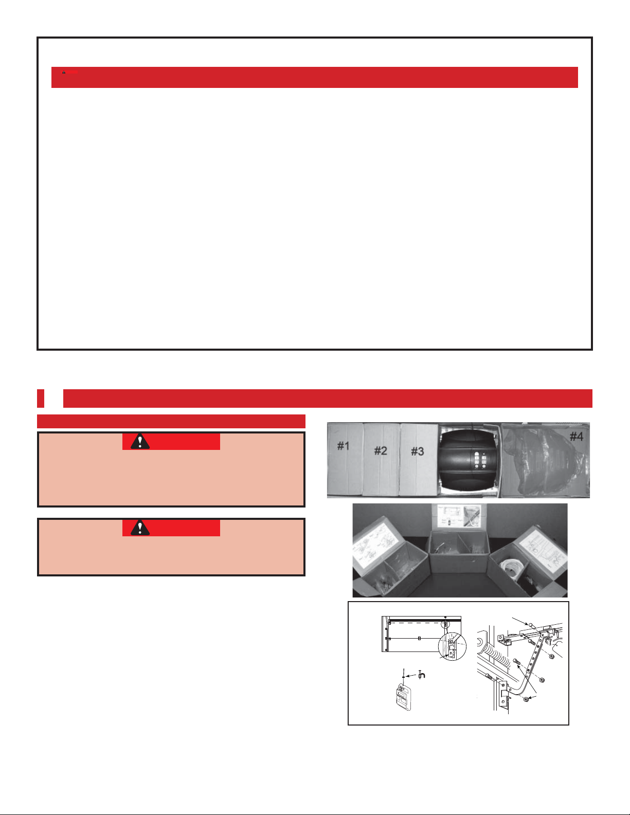
Clear a workspace area to unpack and organize box
and contents for assembly.
1. There are 4, or more, boxes inside the carton. Each
box is numbered 1 - 4. Note that some openers
will contain the same parts and be packaged
with fewer boxes. Carefully remove the three
internal boxes (Labeled #1, 2, and 3) and place
them on the floor for easy access (Fig. 1-1).
These boxes contain assembly parts and the
contents are organized by assembly tasks. For
quick reference inside the lid of each box there is
a label illustrating the components inside.
2. Remove the motor power head and place it
on the floor for later use. Remove box #4 and
place it on the floor for later use.
Bag 4
Door
Door Bracket
Control
Wire
Insulated
Bag 6
Bag 7
Staple
Wall Con trol
Box Label Example
FIG. 1-1 Internal boxes
Bag 5
clevis pin & cotter pin
bolts &
nuts
©2009 Overhead Door Corporation Part Number 37027500123 02/26/2010 REV. 1
9
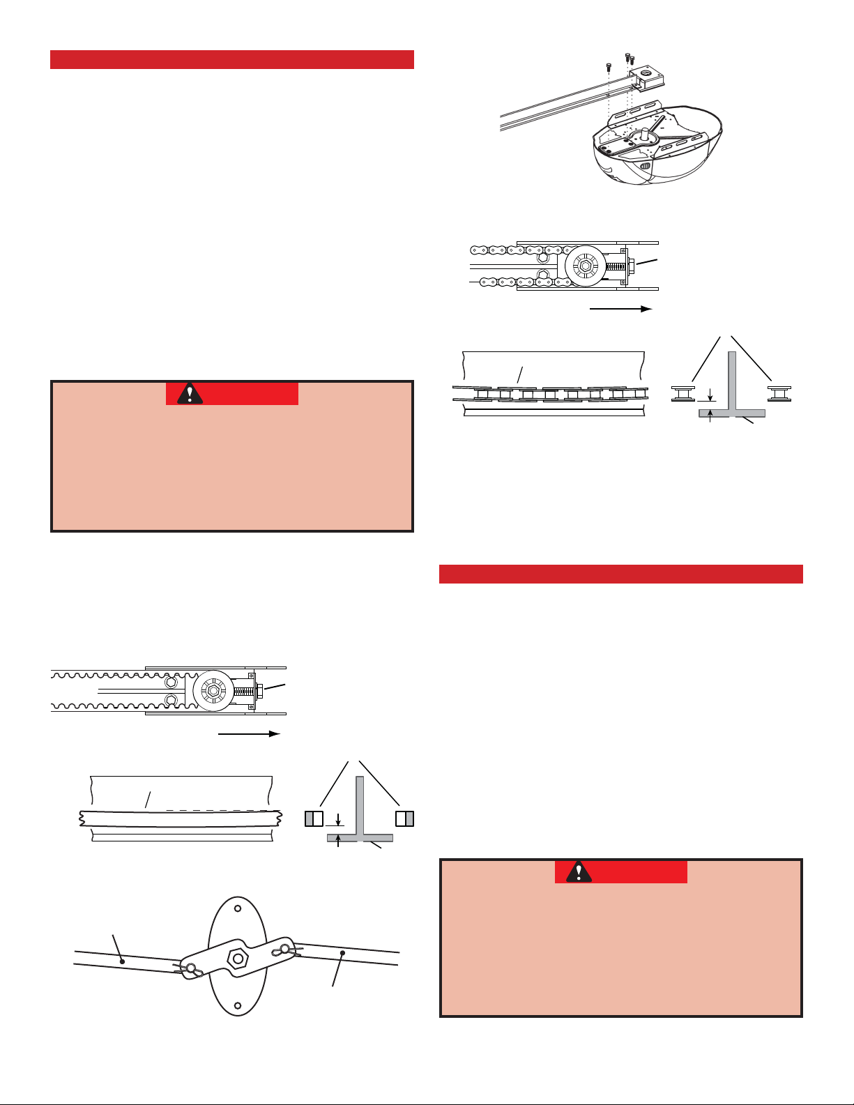
POWER HEAD & CHAIN DRIVE RAIL ASSEMBLY
NOTE: Handle carefully! Drive chain can slide out
of rail.
NOTE: For power head and rail assembly locate
Bag 1 from Box 1.
NOTE: Copy serial number from power head
frame and record it on warranty page.
1. Attach rail assembly to power head by
aligning the sprocket onto the motor shaft.
Use (3) bolts, 5/16 -18 x 1/2" (Fig. 1-2).
2. Tighten the chain by turning the adjustment
nut clockwise. The chain adjustment nut is
located in the Chain Pulley Bracket (opposite rail
end from the power head) (Fig. 1-3).
3. Tighten chain until chain is approximately 1/8
inch above the base of the rail at midpoint on
the rail (Fig. 1-3). Do not over tighten chain.
CAUTION
Use
5/16"-18 x 1/2"
Bolts
FIG. 1-2 Rail - Power head assembly.
Chain Pulley Bracket (at wall end of rail)
Use 1/2" socket
on adjustment nut
Tighten nut to move pulley this direction
Chain
1/8"
Chain
You should have removed all ropes and/or
cables (NOT door lift cable) and disabled the
door lock already. If you have not, remove all
ropes and/or cables and disable garage door
lock NOW before continuing with installation
(Fig. 1-5).
Set assembled power head and rail aside. Begin with
Section 2 INSTALLATION.
Belt Pulley Bracket (at wall end of rail)
Use 1/2" socket
on adjustment nut
Tighten nut to move pulley this direction
Belt
Belt
1/8"
T-Rail at center of rail assembly
T-Rail
FIG. 1-4 Belt adjustment.
Remove
Remove
T-Rail at center of rail assembly
T-Rail
FIG. 1-3 Chain adjustment.
POWER HEAD & BELT DRIVE RAIL ASSEMBLY
NOTE: For power head and rail assembly locate
Bag 1 from Box 1.
NOTE: Copy serial number from power head
frame and record it on warranty page.
1. Attach rail assembly to power head by
aligning the sprocket onto the motor shaft.
Use (3) bolts, 5/16 -18 x 1/2" (Fig. 1-2).
2. Tighten the belt by turning the adjustment
nut clockwise. The belt adjustment nut is located
in the Belt Pulley Bracket (opposite rail end from
the power head) (Fig. 1-4).
3. Tighten belt until belt is approximately 1/8
inch above the base of the rail at midpoint on
the rail (Fig. 1-4). Do not over tighten belt.
CAUTION
You should have removed all ropes and/or
cables (NOT door lift cable) and disabled the
door lock already. If you have not, remove all
ropes and/or cables and disable garage door
lock NOW before continuing with installation
(Fig. 1-5).
FIG. 1-5 Disable garage door lock.
10
©2009 Overhead Door Corporation Part Number 37027500123 02/26/2010 REV. 1
Set assembled power head and rail aside. Begin
with Section 2 INSTALLATION.

INSTALLATION FOR HELP-1.800.929.3667 OR WWW.OVERHEADDOOR.COM
2
HEADER AND DOOR MOUNTING BRACKETS:
WARNING
Header bracket must be fastened to garage
framing. Do NOT fasten to drywall, particle
board, plaster or other such materials.
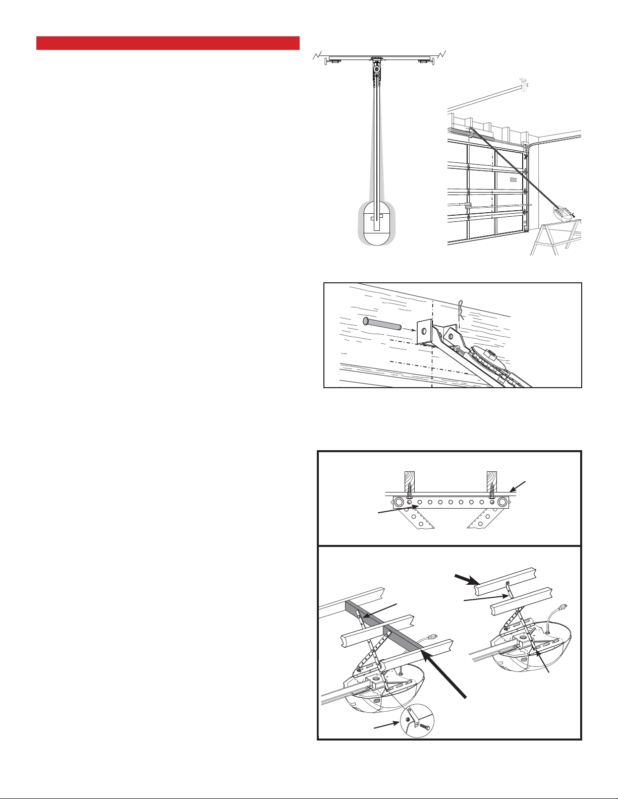
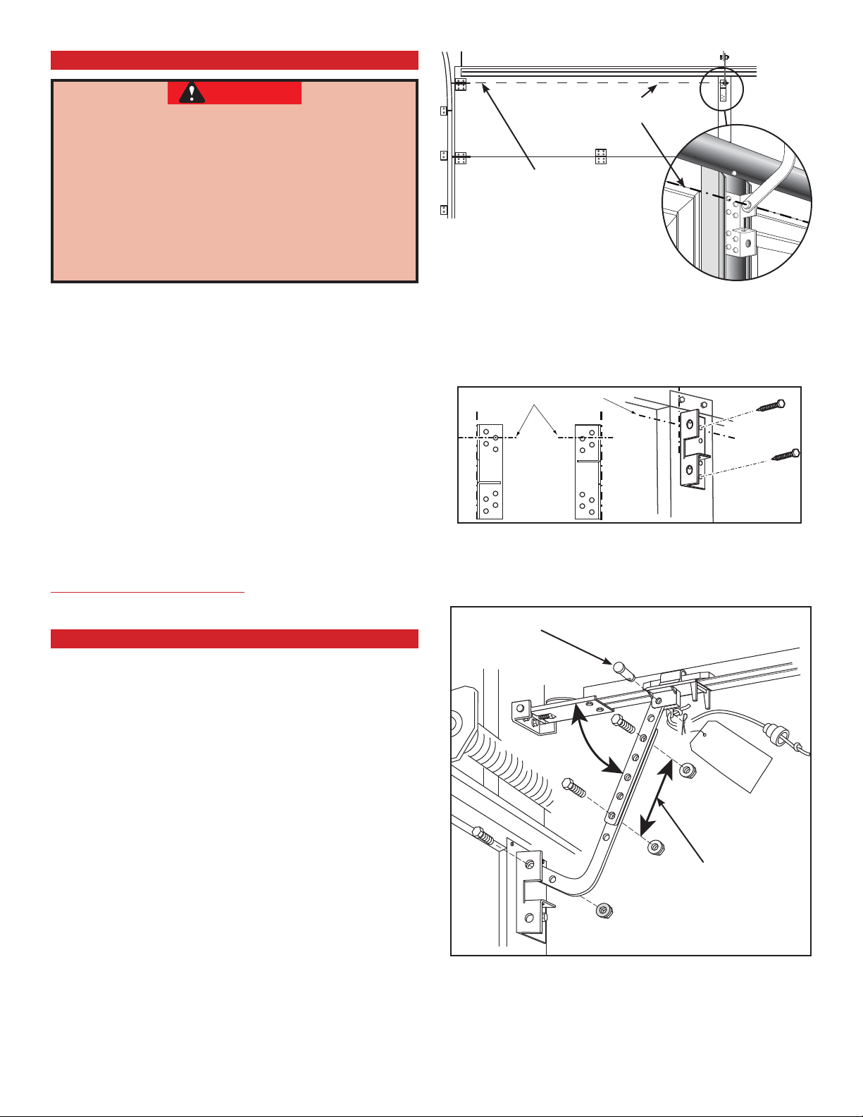
1. Finding header bracket mounting location.
• Close garage door.
– Use a pencil and level.
a) Mark center of garage door (one-half
overall width) on the wall with 6" vertical
line at top edge of door.
b) Continue this line on wall above door for
about 12" (Fig. 2-1, a).
• Raise garage door until top edge of door
reaches its maximum height (Fig. 2-2).
• With door at highest point.
– Measure height from top edge of door to
floor (Fig. 2-2).
• Close door again.
• Mark height measurement on wall above door
(Fig. 2-1, c).
– Make your mark across vertical line made
earlier.
• Add 2-1/2" to height mark just made on wall.
This is location for header bracket (Fig. 2-1, d).
WARNING
Door springs are under high tension. If spring
or its shaft is in the way, measure 2-1/2" above
spring or shaft on the garage door centerline
and mark this height as your location for header
bracket.
d) - fi nal
height mark
c) - door at
highest point
Top of door
in closed
position
FIG. 2-1 Final height mark
HIGHEST POINT OF TRAVEL
2-1/2"
HEADER
SECTIONAL
DOOR
HEADER
b) - extend
vertical line
2-1/2"
a) - 6"
vertical line
TRACK
HIGHEST POINT OF TRAVEL
Do NOT move door spring!
NOTE: If header bracket location needs to be above
header for garage door opening, you need to add
a "mounting surface." A 2" x 6" board securely
attached (board and fasteners not included) to
wall studs on either side of your mark is sufficient
(Fig. 2-3).
NOTE: For header bracket and bolts locate Bag 2
from Box 1.
NOTE: The bolts supplied in Bag 2 are designed to
be used on pressure treated lumber.
2. Mounting the header bracket.
• Hold header bracket against wall (Fig. 2-3).
• Position bracket as shown.
– Place center on vertical line.
– Bottom edge on final height line.
• Mark screw hole locations on wall.
• Drill 3/16" pilot holes at each screw hole mark.
– Fasten header bracket with 2 lag screws
(provided) (Fig. 2-3).
©2009 Overhead Door Corporation Part Number 37027500123 02/26/2010 REV. 1
TRACK
FROM HERE
TO FLOOR
SECTIONAL
DOOR
FROM HERE
TO FLOOR
FIG. 2-2 Finding highest point of travel
final height mark
2-1/2"
door at highest point
final height
mark
door at highest point
FIG. 2-3 Header bracket mounting (on header
& above header)
11
MOUNTING THE OPENER
1. Getting started.
• Position assembled rail on wall next to header
bracket (Fig. 2-4).
– Place material on floor under power head
to protect from scratching. (A box, stool,
or similar device may be needed to clear a
torsion spring.)
NOTE: For header bracket pins locate Bag 2 from
Box 1.
2. Mounting the assembly.
• Attach rail to header bracket using clevis pin
and cotter pin.
• Support power head on step-ladder to prevent
interference with header mounted (torsion)
spring (Fig. 2-5).
HEADER BRACKET
VIEW
FROM
ABOVE
(not to scale)
NO
YES / SÍ / OUI
NO
NOTE: Before final attachment to ceiling, insure
that assembly is in proper alignment (Fig. 2-4).
NOTE: For nuts, bolts, and lag screws locate Bag 3
from Box 1.
• On finished ceilings, locate ceiling joists or
trusses using a stud finder or similar device.
Attach angle iron (not provided) to joists or
trusses through finish material using (provided)
lag screws (Fig. 2-6).
• On unfinished ceilings or open ceilings,
straps may attach directly to joists or trusses.
Depending on the garage construction, extra
framing material (not provided) which may be
required should be installed using appropriate
construction techniques (Fig. 2-6).
NOTE: Refer to your local building codes for
appropriate construction techniques.
• Attach mounting straps to ceiling using lag
bolts (Fig. 2-6).
• Set height of power head to following:
(Fig. 2-6).
a) Rail must clear door at door’s highest point
of travel.
b) Be level or power head slightly below level.
• Securely tighten power head mounting bolts
and nuts.
• Carefully raise and lower door manually. Ensure
door does not contact any section of power
head or rail.
• Check that rail clamp bolts and nuts are tight.
• DO NOT PLUG OPENER IN YET!
FIG. 2-4 Position assembly and align
COTTER PIN
CLEVIS PIN
(Chain drive
shown)
FIG. 2-5 Rail mounting to Header bracket
ANGLE IRON ON FINISHED CEILING
Drywall
Angle Iron
(not provided)
Attach angle iron to beams
UNFINISHED OR OPEN BEAM CEILING
Extra framing NOT needed
Mounting Straps
(not provided)
bolts & nuts
12
Extra framing NEEDED
bolts & nuts
FIG. 2-6 Mounting the power head
©2009 Overhead Door Corporation Part Number 37027500123 02/26/2010 REV. 1
DOOR BRACKET
CAUTION
Doors made of masonite, lightweight wood,
fi berglass, and sheet metal must be properly
braced before mounting door opener.
Contact door manufacturer or distributor for
a bracing kit.
The Overhead Door Corporation is not
responsible for damage caused due to
improperly braced door.
NOTE: For door bracket and bolts locate Bag 4
from Box 2.
1. Finding door bracket mounting location.
• Door bracket is mounted as high on door
as possible along vertical centerline and NO
LOWER THAN top set of rollers (Fig. 2-7).
2. Mounting the door bracket.
• Proper bracing should be verified at this point.
– Align door bracket centered on your vertical
centerline (Fig. 2-8).
– Attach using 3 self-drilling screws for sheet
metal or other light weight material.
– Use lag screws (not provided) for solid
wooden sectional doors.
Centerline
Centerline even with or
above top roller
FIG. 2-7 Mounting door Bracket
centerline of top roller
FIG. 2-8 Examples of door bracket positioning
NOTE: For solid wood doors, carriage bolts
WITHOUT SLOTTED HEADS (not included) may also
be used for attaching door bracket).
INSTALL DOOR ARMS
NOTE: For door arm nuts and bolts, clevis and
cotter pins locate Bag 5 from Box 2.
1. Attach the arms.
• Fasten short branch of curved door arm to door
bracket using bolt and locking nut (Fig. 2-9).
• Fasten straight arm to carriage using clevis pin
and cotter pin (Fig. 2-9).
2. Connecting the arms.
• Slide carriage back and forth to adjust arm
length.
– Position the straight arm 50º down from the
rail.
• With the arms arranged in this position, fasten
arms together using bolts and nuts spaced as
far apart as possible (Fig. 2-9)
Short Clevis Pin & Cotter Pin
50˚
Bolts as far
apart as
possible
FIG. 2-9 Attaching door arms
©2009 Overhead Door Corporation Part Number 37027500123 02/26/2010 REV. 1
13
WALL CONTROL INSTALLATION FOR HELP-1.800.929.3667 OR WWW.OVERHEADDOOR.COM
3
HEADER AND DOOR MOUNTING BRACKETS:
WARNING
Verify there is NO power to the opener before
installing wall control wires and wall control.
CAUTION
Staples which are too tight can cut or pinch
wires. Cut or pinched wires can cause the
wall control to stop working. When using the
insulated staples, make sure you fasten them
only as tightly as needed to hold the wire
snugly.
WARNING
Use of any other wall control can cause the
door to operate unexpectedly and the light
not to work. Use only the included wall
control.
NOTE: Wall control will not operate until limits are
set.
NOTE: For Wall Control, wire and insulated staples
locate Bags 6 and 7 from Box 2.
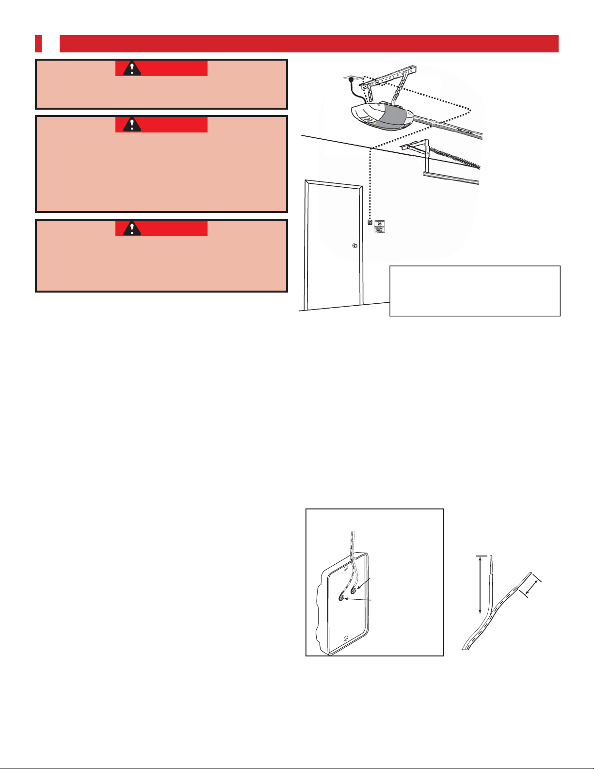
1. Wall Control location.
• Wall Control location should be in direct sight
of door.
• It should be at least five feet (5’) above floor to
prevent small children from operating door.
• It must be away from any moving parts. (You
should NOT be able to reach the garage door
while standing at wall control.)
• Wall Control board screw connections are
polarized, (+) positive and (-) negative.
2a. Wiring (If pre-wired).
• Locate wall control pre-wired wire ends
(Fig. 3-1). (They should be located within the
guidelines mentioned above.)
• Split and strip ends of wire (Fig. 3-2).
• Fasten wire to wall control board screws on
back of wall control.
– Striped wire to the + (plus) terminal.
– White wire to the - (minus) terminal.
2a. Wiring (If NOT pre-wired).
• Pick a convenient location for mounting wall
control using the guidelines mentioned above
(Fig. 3-1).
• Run wire from wall control to power head
(Fig. 3-1).
• Split and strip ends of wire (Fig. 3-2).
• Fasten wire to control board screws on back of
wall control button.
– Striped wire to the + (plus) terminal.
– White wire to the - (minus) terminal.
Wire from
power head
to Wall Control
Wall
Control
"Entrapment"
warning label
Separate
entry door
This is an example of wire routing
when NOT pre-wired. Your wire
routing may be different.
EXAMPLE ONLY!
FIG. 3-1 Wall control wire routing
White
or
–
Black
or
+
Striped
2"
FIG. 3-2 Splitting and stripping
1/2"
14
©2009 Overhead Door Corporation Part Number 37027500123 02/26/2010 REV. 1
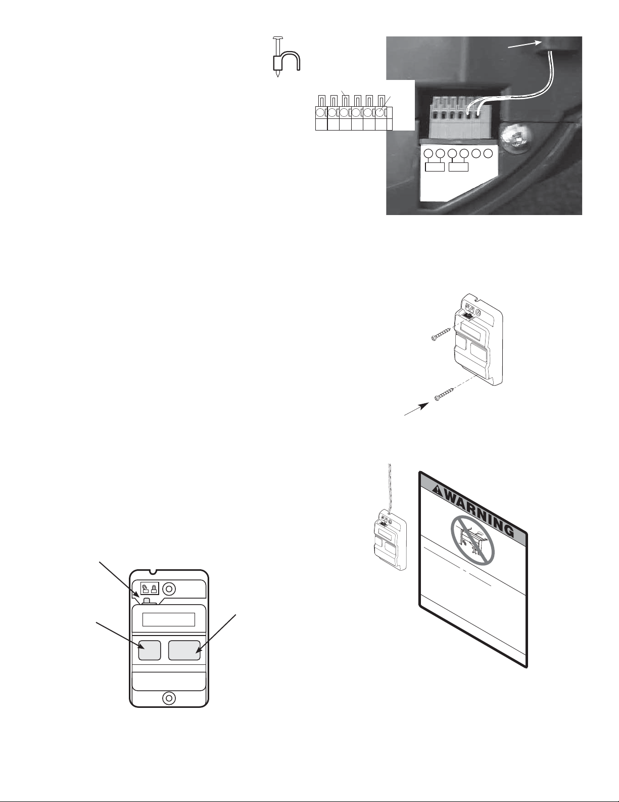
3. Securely fasten wires.
+–
PB
Infared Sensor
• Securely fasten wires to ceiling and wall
using insulated staples provided.
– Use insulated staples.
– Staples should be snug only.
• If rear cover is attached to power head, remove
it.
• On power head.
– Route wall control wires through wire guide.
– Split and strip ends of wire (Fig. 3-2 on
previous page).
– Insert wire into terminal holes and lightly
press in the orange locking clips above each
terminal hole. (You can use a pencil or small
screwdriver to comfortably press in locking
clips.) The white wire into #1 terminal hole
and striped wire into the #2 terminal hole.
– Confirm wire lock by lightly tugging on the
wire. The wire should remain in the terminal
hole.
• Do NOT install rear cover yet!
Insulated
Staple
Locking
Clips
56
1234
Terminal
Holes
(Power Head With Rear Cover Removed)
FIG. 3-3 Insert wires
Wire
Guide
123456
4. Mounting.
• Fasten wall control to wall with 2 screws
(provided) (Fig. 3-4).
• Remove protective backing from "Entrapment"
warning label (Fig. 3-5). The "Entrapment" label
is located in the center of this manual.
– Stick label on wall near wall control.
Vacation Lock
Independent
Light Control
"Open/Close"
Button
FIG. 3-4 Mounting wall control
Childcanbe pinned under automatic garage
Death or serious injury can result.
•
Never let child walk or run under moving door.
•
Never let child use door opener controls.
•
Always keep moving door in sight.
•
If person is pinned, push control button or use
emergency release.
•
Tes t do or
R
e
fer to your
opener m
P
la
ce 1
If door fails to reverse on
1
/
If opener s
2
ow
-inch objec
’
n
er'
till fails
M
o
to rev
u
n
t
D
w
o
all con
not remove or
t
ro
l
out of child
P
on
thly:
sm
an
t
(or 2x4 laid flat)
ual.
contact, adjust opener.
erse door
la
c
paint over this label.
e n
's
e
xt to wa
rea
,
c
h
(at least 5 fee
l
l co
repair or
ntro
on floor.
l
.
replace opener.
t ab
ov
e
door.
.
f
loo
r)
.
©1
99
9
FIG. 3-5 Mounting Entrapment warning label
FIG. 3-6 Wall control
©2009 Overhead Door Corporation Part Number 37027500123 02/26/2010 REV. 1
15
SAFE-T-BEAM® SYSTEM INSTALLATION FOR HELP-1.800.929.3667 OR WWW.OVERHEADDOOR.COM
4
WARNING
There should be no electrical power to the
opener while installing Safe-T-Beam
®
wires.
If you have plugged in the power cord—
UNPLUG IT NOW!
NOTE: The opener will not close the door
automatically unless the Safe-T-Beam® System is
installed.
NOTE: For Sensors, screws, wire, and insulated
staples locate items and Bag 8 from Box 3.
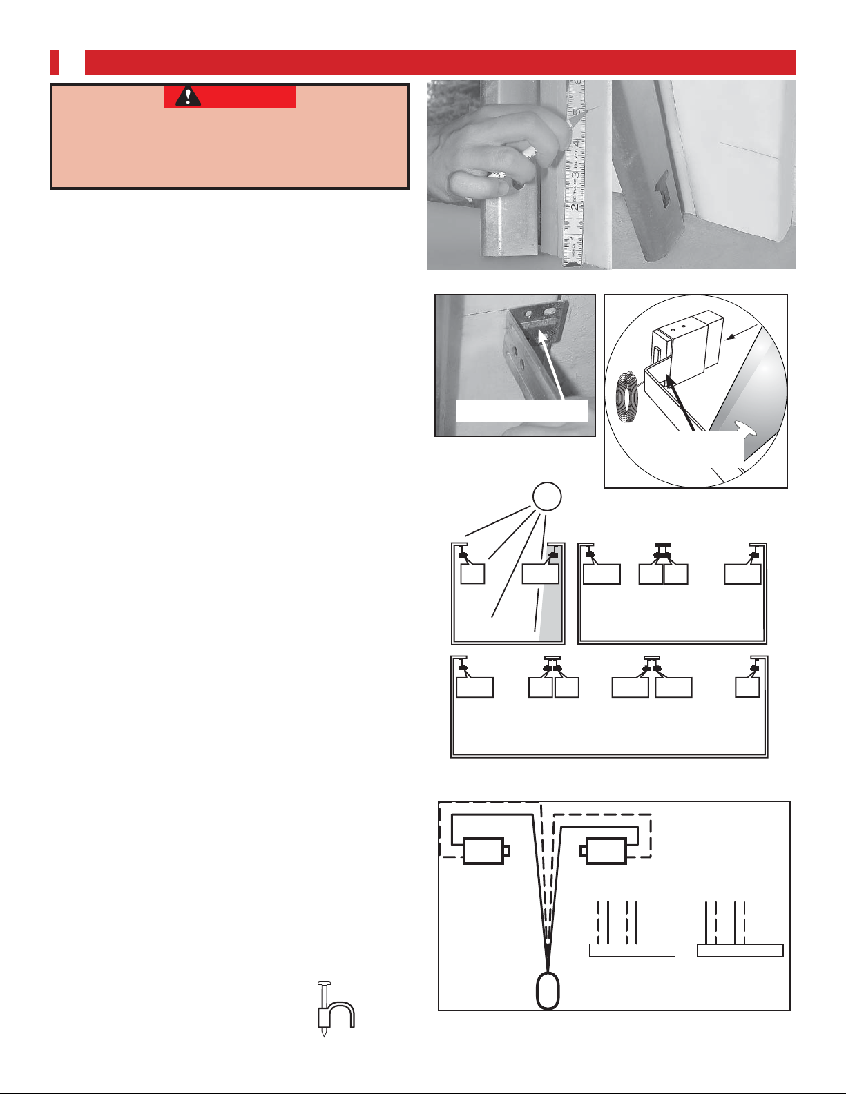
1. Mounting brackets
• Mark both sides of garage door frame or wall no
higher than 6" and no lower than 5" above floor
(Fig. 4-1).
• Hold bracket against door frame or wall.
– Check if brackets extend out from wall far
enough, so tongue of bracket is beyond door,
tracks or any door hardware.
– If not:
a) Mounting bracket extensions are available
through an authorized Overhead Door
dealer.
b) Blocks of wood, etc. may be substituted for
extensions.
• Locate top of bracket on your mark (Fig. 4-2).
• Fasten each with 2 screws (Fig. 4-2).
NOTE: Mounting brackets can be attached to the
floor or concrete rim using concrete anchors (not
provided).
2. Mounting Safe-T-Beam® Source (Red LED) and
Sensor (Green LED)
• If garage has only one garage door.
– Determine which side of garage receives most
direct sunlight (Fig. 4-4).
– Red LED should always be on sunny side
whenever possible (Fig. 4-4).
• For multiple doors.
– Preventing crossed signals is critical.
– Place source and sensor modules on adjacent
doors facing in opposite directions (Fig. 4-4).
NOTE: Mounting brackets can be attached to the
floor or concrete rim using concrete anchors (not
provided).
• Slide source/sensor onto tongue of bracket
until it clicks into place (Fig. 4-3).
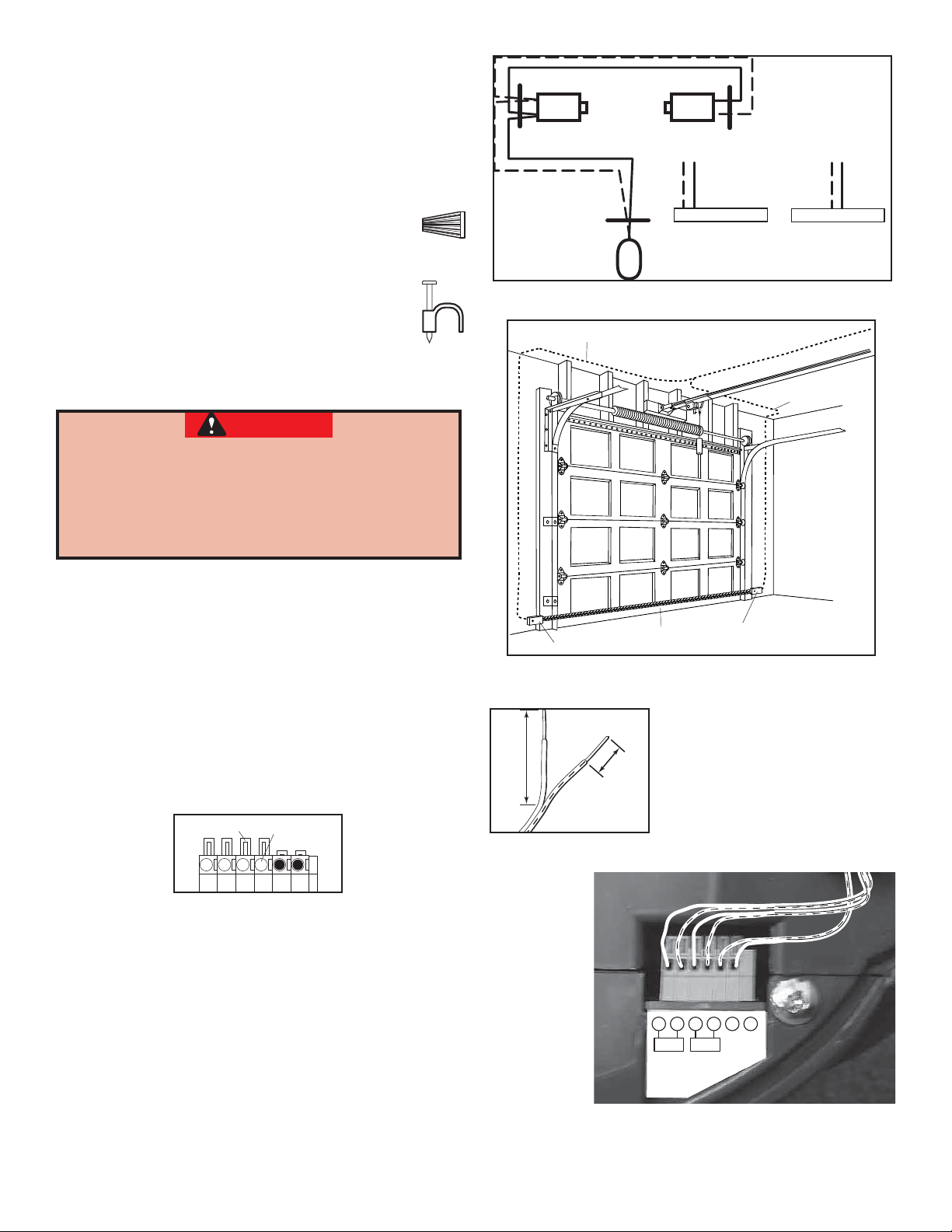
3. Wiring (If NOT pre-wired)
®
• Route wire from Safe-T-Beam
sensors to power
head using method shown in (Fig. 4-5a).
• Securely fasten wires to wall and ceiling as you
go (Fig. 4-6 on next page).
– Use insulated staples.
– Staples should be snug only.
16
©2009 Overhead Door Corporation Part Number 37027500123 02/26/2010 REV. 1
Insulated
Staple
FIG. 4-1 Mark door frame.
e
d
i
l
s
center of bracket
FIG. 4-2
Mounting brackets
SUN
FIG. 4-3 Attach
bracket
tongue
sensors to brackets
RED
LED
ONE DOOR
GARAGE
GREEN
LED
THREE DOOR
GARAGE
GREEN
LED
RED
LED
RED
LED
GREEN
LED
TWO DOOR
GARAGE
GREEN
LED
RED
LED
RED
LED
GREEN
LED
GREEN
LED
RED
LED
FIG. 4-4 Safe-T-Beam® source and sensor
locations
Red
Source Sensor
Power
Head
Green
6 5 4 3 2 1
or
6 5 4 3 2 1
Dashed Line = striped wire
Solid Line = white wire
FIG. 4-5a Source and sensor wiring methods
+–
PB
Infared Sensor
3b. Wiring (If pre-wired)
• Route wire from wall to Safe-T-Beam® sensors
(Fig. 4-5b).
• Splice pre-wiring to shortened sensor wire,
match wire pairs dash-to-dash and plain-to-
plain.
– Trim sensor wire to approximately one foot
(12 inches) from sensor.
– Split and strip ends of sensor wires
and pre-wired wires (Fig. 4-7).
– Splice wires together with (provided)
wire nuts.
• Route wire from ceiling to power head
(Fig. 4-5b).
• Securely fasten wires where they exit
wall and ceiling as you go.
– Use insulated staples.
– Staples should be snug only.
CAUTION
Wire Nut
Insulated
Staple
Wall
Red Green
Source Sensor
Ceiling
Wall
6 5 4 3 2 1
or
6 5 4 3 2 1
Dashed Line = striped wire
Power
Head
Solid Line = white wire
FIG. 4-5b Pre-Wired source and sensor wiring
method
Wire
Insert Wire
Into Connector
Wire
Staples which are too tight can cut or pinch wires.
Cut or pinched wires can cause the Safe-T-Beam
System to stop working. When using the insulated
staples, make sure you fasten them only as tightly
as needed to hold the wire snugly.
4. Split and strip ends of sensor wires (Fig. 4-7).
NOTE: For rear cover locate Box 4.
®
5. Attach Safe-T-Beam
wire to power head wire
terminal.
®
• Route Safe-T-Beam
wires through wire guide.
– Insert wire into terminal holes and lightly
press in the orange locking clips above each
terminal hole. (You can use a pencil or small
screwdriver to comfortably reach in and lightly
press down locking clips.) Insert white wires
to ‘even’ numbered terminal holes and striped
wires into ‘odd’ terminal holes (Fig. 4-8).
Locking
Clips
56
Terminal
Holes
1234
®
Sensor
Sensor
Invisible Light Beam
Protection Area
Use this
wire routing
if NOT pre-wired
FIG. 4-6 Wire routing
2"
1/2"
FIG. 4-7 Splitting and
stripping
– Confirm wire lock by lightly tugging on the
wire. The wire should remain in the terminal
hole.
• Do not install the white (lamp) cover at this
time.
NOTE: Safe-T-Beam® alignment check must be
performed following connection to electrical
power (see page 18). DO NOT PLUG IN YET!
©2009 Overhead Door Corporation Part Number 37027500123 02/26/2010 REV. 1
123456
(Power Head With Rear Cover Removed)
FIG. 4-8 Insert wires
17
 Loading...