

Overhead door INFINITY 2000 Installation, Programming, Operating Manual

INFINITY™ 2000
RESIDENTIAL WALL MOUNT OPENER
INSTALLATION, PROGRAMMING, OPERATION,
TROUBLESHOOTING & MAINTENANCE MANUAL
DO NOT use photocells from other manufacturers or openers with this opener.
INSTALLER: LEAVE THIS MANUAL WITH HOMEOWNER
HOMEOWNER: SAVE THIS MANUAL FOR FUTURE REFERENCE
!
WARNING
To reduce the risk of injury to persons or damage to property, use this opener only
with a residential sectional door with front torsion springs.
!
AVERTISSEMENT
Pour réduire le risque de blessures corporelles ou de dégâts matériels, utilisez cet ouvre-porte uniquement avec
une porte sectionnelle résidentielle munie de ressorts de torsion avant.
SERIAL NUMBER DECAL
© 2019 Overhead Door Corporation. Overhead Door, the Ribbon logo, Infinity, CodeDodger, OHD Anywhere, and Safe-T-Beam are registered trademarks of
Overhead Door Corporation. Overhead Door Corporation. All other trademarks are the property of their rightful owners. Consistent with our policy of continuing
product improvements, without notice or obligations. HomeLink is a registered trademark of Gentex Corporation. Car2U is a registered trademark of Lear
Corporation. Bluetooth is a registered trademark of SIG.
iDCM SERIAL NUMBER DECAL
40686503927, 07/2019
INDEX
Section Information Page
Standard & Safety Features:
1
.................................................................................................................1
SAVE THESE INSTRUCTIONS
READ AND FOLLOW ALL INSTRUCTIONS
Safety & General Information:
2
Introduction ....................................................................................... 2
Safety Notications ..........................................................................2
Important Installation Instructions ............................................ 3
Opener Installation:
3
Pre-Installation Considerations ................................................... 4
Pre-Installation Permanent Input Wiring .................................5
Installing Cable Keepers ................................................................6
Installing Opener .......................................................................... 7-9
Installing Door Lock .......................................................................10
Wire Opener, Install & Wire Accessories:
4
Wire Door Lock ................................................................................11
Install And Wire Safe-T-Beam® ...................................................12
Install Wireless Wall Console .......................................................13
Install Led Light Fixture ................................................................13
Install And Wire Optional Wired Wall Console .....................14
Install And Wire Optional External Interlock ........................14
Install Bottom Cover ......................................................................14
Apply Power To Opener ...............................................................15
Programming Opener And Accessories:
5
Introduction .....................................................................................16
Adjusting For Drum Selection ...................................................17
Setting Down Limit ........................................................................18
Setting Up Limit ..............................................................................19
Setting Force Control And Contact Reverse .........................20
Programming Additional Remote Controls ..........................21
Programming Accessories:
Wireless Keypad* ............................................................................22
Programming Vehicle Controls* ........................................23-24
Programming OHD Anywhere® .........................................25-26
FCC Part 15.21 Statement:
Changes or modications not expressly
approved by the party responsible for
compliance could void the user’s authority to
operate the equipment.
FCC / IC Statement:
This device complies with FCC Part 15 and
Industry Canada licence-exempt RSS
standard(s). Operation is subject to the
following two conditions: (1) this device
may not cause harmful interference, and
(2) this device must accept any interference
received, including interference that may cause
undesired operation of the device.
Le présent appareil est conforme aux CNR
d’Industrie Canada applicables aux appareils
radio exempts de licence. L’exploitation est
autorisée aux deux conditions suivantes : (1)
l’appareil ne doit pas produire de brouillage,
et (2) l’utilisateur de l’appareil doit accepter
tout brouillage radioélectrique subi, même si le
brouillage est susceptible d’en compromettre
le fonctionnement.
6
7
8
9
10
Special Installation Information:
Changing Force Settings .............................................................27
Clearing Remote/Accessory Memory .....................................28
Locating Safe-T-Beam® (multiple doors) ...............................29
Safe-T-Beam® Troubleshooting .................................................29
Installing Battery Back Up ...........................................................30
Adding And Programming Additional Accessories ...........31
Maintenance:
Important Safety Instructions ....................................................32
Regular Maintenance Schedule ................................................33
Door Inspection & Maintenance ...............................................33
Remote Battery Replacement ....................................................33
Troubleshooting & LED Signals......................................34-36
Replacement Parts ...............................................................37-39
DASMA Information ............................................................40-41
For patent info visit www.overheaddoor.com/patents
* Abbreviated versions. See instructions that accompany
ACCESSORY or VEHICLE OWNERS MANUAL for full details,
WARNINGS, CAUTIONS and instructions.
1
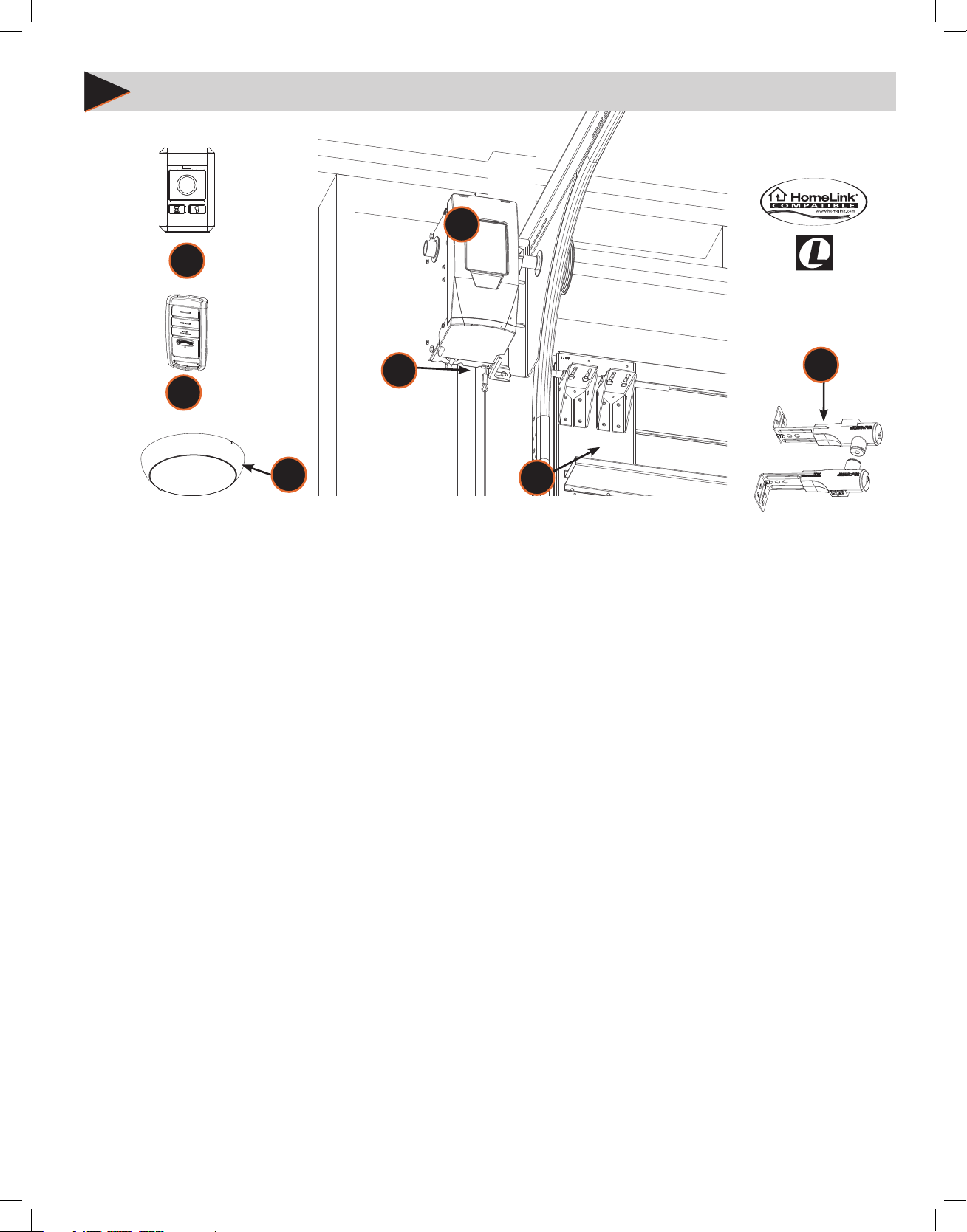
STANDARD AND SAFETY FEATURES
5
6
Vehicle
Compatible
3
1
7
4
1. Safe-T-Beam® (STB) Non-Contact Reversing System:
• Places an infrared beam across the door opening.
• Only aects the DOWN travel of the door.
• Stops an open door from closing or reverses a door while in the down travel.
• Reversing system can be overridden with constant pressure on the wired wall console only.
• The door will stop and reverse to the full open position if beam is obstructed.
• Self-diagnostic LEDs on STBs and Powerhead alert to operational issues (See Locating Safe-T-Beam® (for multiple doors) &
Troubleshooting section in this manual for more information).
2. Contact Reversing System:
• Force control automatically reverses a closing door upon contact with an obstruction.
3. Manual Emergency Release pull handle & cord:
• Manually releases door from door opener. Used during a power failure or other emergency to allow manual opening and closing
of the door.
2
4. Automatic Bluetooth® LED Light Fixture:
• Lighting Fixture turns ON when door is activated and automatically turns OFF 4 minutes later.
• Can be activated/deactivated manually from the wall console.
5. Integrated OHD Anywhere® :
• Available with select models, allows operation of the garage door opener with a secure mobile device application (app) from
OHD Anywhere®.
6. Wireless Wall Console:
• Wireless Wall Console operates door opener from inside garage with an open/close button.
• Manual light control and override.
• OPEN/CLOSE Delay button. Adds an operation delay. Press once for 10 seconds, twice for 20 seconds, three times for 30 seconds.
7. CodeDodger® Encryption, Factory Programmed Remote(s) :
• An encryption system that enhances the security of the door opener by continuously changing the access code each time the
remote is used.
• Factory programmed remote control(s) included with this opener.
Not Shown- Battery Backup (Included on select models) :
• Mounts to bottom of opener and provides power for opener operation during power outages.
1
!
!
!
!
!
!
2
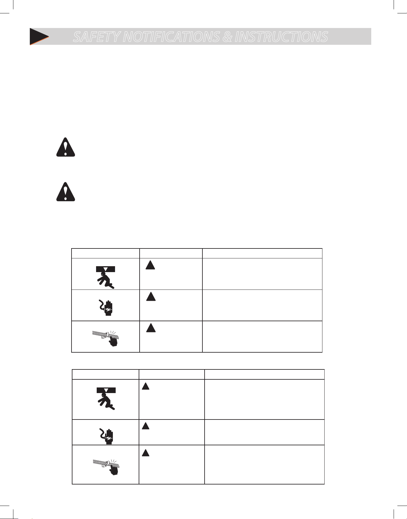
SAFETY NOTIFICATIONS & INSTRUCTIONS
OVERVIEW OF POTENTIAL HAZARDS
READ THIS SAFETY INFORMATION
Garage doors are large, heavy objects that move with the help of springs under high tension and electric motors. Since moving objects, springs under tension,
and electric motors can cause injuries, your safety and the safety of others depend on you reading the information in this manual. If you have questions or do
not understand the information presented, call your nearest trained door system technician or visit our website at www.overheaddoor.com
CONVENTIONS USED IN THESE INSTRUCTIONS
The following safety alert symbol and signal words are used throughout this manual to call attention to and identify dierent levels of hazards and special
instructions.
This is the safety alert symbol. This symbol alerts you to potential hazards that can kill or hurt you and others. All safety messages will follow the safety alert
symbol and the word
Tous les messages concernant la sécurité seront indiqués après un symbole d’alerte de la sécurité et l’une des mentions suivantes “DANGER”,
”AVERTISSEMENT” ou “MISE EN GARDE”.
“DANGER”, “WARNING”, or
• DANGER
• WARNING
•
•
• DANGER signale une situation dangereuse imminente qui, si elle n’est pas évitée, risque d’entraîner des blessures graves, voire mortelles.
• AVERTISSEMENT signale une situation potentiellement dangereuse qui, si elle n’est pas évitée, risque d’entraîner la mort ou des blessures
• MISE EN GARDE signale une situation potentiellement dangereuse qui, si elle n’est pas évitée, risque d’entraîner des blessures ou des
• Le terme REMARQUE est utilisé pour signaler les étapes importantes à suivre ou d’importants éléments à prendre en considération.
indicates an imminently hazardous situation which, if NOT avoided, will result in death or serious injury.
indicates a potentially hazardous situation which, if NOT avoided, could result in death or serious injury.
CAUTION
indicates a potentially hazardous situation which, if NOT avoided, may result in injury or property damage.
The word
graves.
dommages matériels.
NOTE is used to indicate important steps to be followed or important considerations.
“CAUTION”.
IMPORTANT SAFETY INSTRUCTIONS
POTENTIAL HAZARD EFFECT PREVENTION
MOVING DOOR
ELECTRICAL SHOCK
HIGH SPRING TENSION
WARNING
Could result in Serious
Injury of Death
WARNING
Could cause Serious
Injury or Death
WARNING
Could cause Serious
Injury or Death
Do Not operate unless the doorway is in sight and free of
obstructions. Keep people clear of opening while door is moving.
Do Not allow children to play with the door opener.
Do Not change opener control to momentary contact unless an
external reversing means is installed.
Do Not operate a door that jambs or one that has a broken spring.
Turn o electrical power before removing opener cover.
When replacing the cover, make sure wires are not pinched or near
moving parts.
Opener must be electrically grounded.
Do Not try to remove, repair or adjust springs or anything to which
door spring parts are fastened such as wood block, steel brackets,
cables or any other structure or like item.
Repairs and adjustments must be made by a trained service
representative using proper tools and instructions.
IMPORTANTES CONSIGNES DE SÉCURITÉ
DANGER POTENTIEL EFFET PRÉVENTION
PORTE EN MOUVEMENT
CHOC ÉLECTRIQUE
TENSION ÉLEVÉE RESSORT
AVERTISSEMENT
Pourrait entraîner des blessures
graves voire la mort
AVERTISSEMENT
Pourrait entraîner des blessures
graves voire la mort
AVERTISSEMENT
Pourrait entraîner des blessures
graves voire la mort
2
Utiliser uniquement si la porte est en vue et libre de tout obstacle.
Ne laisser personne se tenir dans l’ouverture de la porte pendant
qu’elle est en mouvement.
Ne pas permettre aux enfants de jouer avec l’opérateur de la porte.
Ne pas modier la commande de l’opérateur à contact momentané
à moins qu’un moyen d’inversion externe soit installé.
Ne pas faire fonctionner une porte qui bloque ou dont le ressort
est cassé.
Couper le courant avant d’enlever le couvercle de l’opérateur.
Lorsque le couvercle doit être remplacé, s’assurer que les ls ne sont
ni coincés ni près des pièces mobiles.
L’opérateur doit être correctement mis à la terre.
Ne pas essayer d’enlever, réparer ni ajuster les ressorts ou toute
autre pièce à laquelle le ressort de la porte est attaché, y compris
blocs de bois, supports en acier, câbles ou autres articles
semblables.
Les réparations et les réglages doivent être eectués par technicien
qualié qui se sert d’outils appropriés et qui respecte les
instructions.
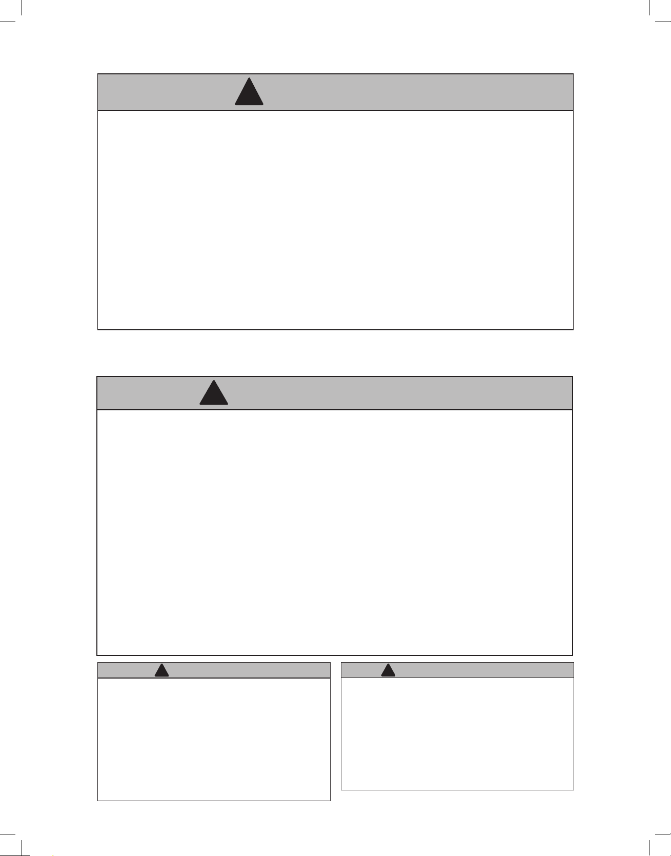
IMPORTANT INSTALLATION INSTRUCTIONS
WARNING
!
TO REDUCE THE RISK OF SEVERE INJURY OR DEATH
READ AND FOLLOW ALL SAFETY, INSTALLATION AND OPERATION INSTRUCTIONS. If you have any questions or do not
understand an instruction, call Overhead Door Corporation.
• READ AND FOLLOW ALL SAFETY, INSTALLATION AND OPERATION INSTRUCTIONS. If you have any questions or do not understand an
instruction, call Overhead Door Corporation.
• DO NOT install opener on an improperly balanced door. An improperly balanced door could cause severe injury. Repairs and
adjustments to cables, spring assembly and other hardware must be made by a trained service person using proper tools and
instructions.
• Remove all ropes, and disable all locks connected to the door before installing opener.
• Where possible, install the door opener 7 feet or more above the oor. For products having an emergency release, mount the
emergency release within reach, but at least 6 feet above the oor and avoiding contact with vehicles to avoid accidental release.
• DO NOT connect the opener to the source of power until instructed to do so.
• Locate the Wall Control: (a) within sight of the door, (b) at a minimum height of 1.53 m (5 ft) above oors, landings, steps or any other
adjacent walking surface so small children are not able to reach it, and (c) away from all moving parts of the door.
• Install the entrapment WARNING label next to the wall button or console, in a prominent location. Install the emergency release
handle on the emergency release cord.
• The opener must reverse when the door contacts a 1-1/2 inch high object on the oor at the center of the doorway. This is about the
size of a 2” x 4” board laid at.
IMPORTANTES INSTRUCTIONS D’INSTALLATION
!
AVERTISSEMENT
POUR RÉDUIRE LES RISQUES DE BLESSURES GRAVES
VOIRE MORTELLES
LIRE ET SUIVRE ATTENTIVEMENT TOUTES LES INSTRUCTIONS D’INSTALLATION ET DE FONCTIONNEMENT AINSI QUE TOUTES LES
CONSIGNES DE SÉCURITÉ. Si vous avez des questions ou si vous ne comprenez pas une instruction, veuillez contacter directement
Overhead Door Corporation.
• NE PAS installer l’opérateur sur une porte mal équilibrée. Celle-ci pourrait entraîner de graves blessures. Les réparations et les réglages
des câbles, ensembles de ressort ou tout autre article de quincaillerie doivent être eectués par un professionnel qui se sert d’outils
appropriés et qui respecte les instructions.
• Enlever toutes les cordes et désactiver toutes les verrous de la porte avant l’installer l’opérateur.
• Dans la mesure du possible, installer l’ouvre-porte à 2,1 m ou plus au-dessus du sol. Pour les produits dotés d’un cordon de
déclenchement d’urgence, installer le déclenchement d’urgence mais au moins à 1,8 m au-dessus du sol en évitant tout contact avec
les véhicules pour éviter qu’ils ne soient déclenchés accidentellement. NE PAS connecter l’opérateur à la source d’alimentation tant que
l’instruction n’est pas donnée.
• Installez le bouton de commande a) à un endroit que l’on peut voir de l’embrasure de la porte; b) à une hauteur minimale de 1,53 m (5
pi) du sol — an que les jeunes enfants ne puissent pas l’atteindre ; et c) à l’écart des
• Pièces mobiles de la porte.
• Placer l’étiquette d’AVERTISSEMENT en cas de coinçage à proximité du bouton mural ou de la console de manière à ce qu’elle soit bien
en évidence. Installer la poignée du cordon de déclenchement d’urgence.
• L’opérateur doit s’inverser lorsque la porte entre en contact avec un objet d’une hauteur de 3,8 cm placé sur le sol, au centre de
l’ouverture de la porte. Ceci équivaut environ à une planche de 5 x 10 cm posée à plat sur le sol.
!
WARNING
Opener is equipped with grounded electrical plug for
your protection, and only ts grounded electrical
outlets. DO NOT alter plug in any way! If you have no
grounded outlets, have one installed by a licensed
electrician. Opener must be properly grounded to prevent
personal injury and equipment damage. NEVER USE AN
EXTENSION CORD! Check local building codes for any
requirement that you must have a permanent hard-wired
connection. Permanent hard-wired connections must be
performed by a licensed electrician using proper tools and
instructions.
!
AVERTISSEMENT
L’opérateur, qui est équipé d’une prise électrique mise à la terre
pour votre protection est compatible uniquement avec des
prises électriques mises à la terre. NE PAS modier la che dune
quelconque manière. Si vous n’avez pas de prises mises à la terre,
faites-en installer par un électricien agréé. L’opérateur doit être
correctement mis à la terre pour éviter les blessures corporelles et
des dommages matériels. NE JAMAIS UTILISER DE RALLONGE!
Vériez les codes locaux des bâtiments pour connexions câblées
permanente. Les connexions câblées permanentes doivent
être eectuées par un électricien agréé qui se servira d’outils
appropriés et respectera les consignes.
3
A
X
!
!
3
PRE-INSTALLATION CONSIDERATIONS
Compatibility Considerations:
The Innity 2000 Residential Wall Mount opener is intended for use on:
• Standard lift up to 14 feet tall, using industry standard APCO 400.8 , 400.12 and 5250.18 drums or equivalent.
• Hi-lift sectional doors up to 14 feet tall and 84 inches maximum of high lift using industry standard APCO 400.54 , 5250.54 and
500.84 drums or equivalent.
• Vertical lift doors up to 14 feet tall, using industry standard APCO 850.11 and 1100.18 drums or equivalent.
• Doors up to 18 feet wide not to exceed 180 square feet and 850 lbs. balance weight.
• Only doors that use torsion springs with a torsion bar diameter of 1 in. solid or hollow 14 or 16 ga. tubular steel.
• Not compatible with low headroom outside hook-up, i.e. reverse wound drums.
Garage door hardware (springs, cables, brackets, pulleys, etc.) are under
WARNING
extreme pressure and tension.
DO NOT attempt to repair or adjust door springs or any hardware, and DO NOT
OPERATE garage door automatically or manually if door is improperly
balanced or springs are broken.
CONTACT A TRAINED DOOR SYSTEM TECHNICIAN.
La quincaillerie de la porte de garage (ressorts, câbles, supports, poulies, etc.)
sont sous des pressions et des tensions extrêmes.
NE PAS réparer ni régler les ressorts de la porte ou toute autre pièce de
quincaillerie et NE PAS ACTIONNER la porte manuellement ou
automatiquement si elle n’est pas correctement équilibrée ou si des ressorts
sont cassés.
CONTACTEZ UN TECHNICIEN SPÉCIALISÉ EN SYSTÈME DE PORTES
AVERTISSEMENT
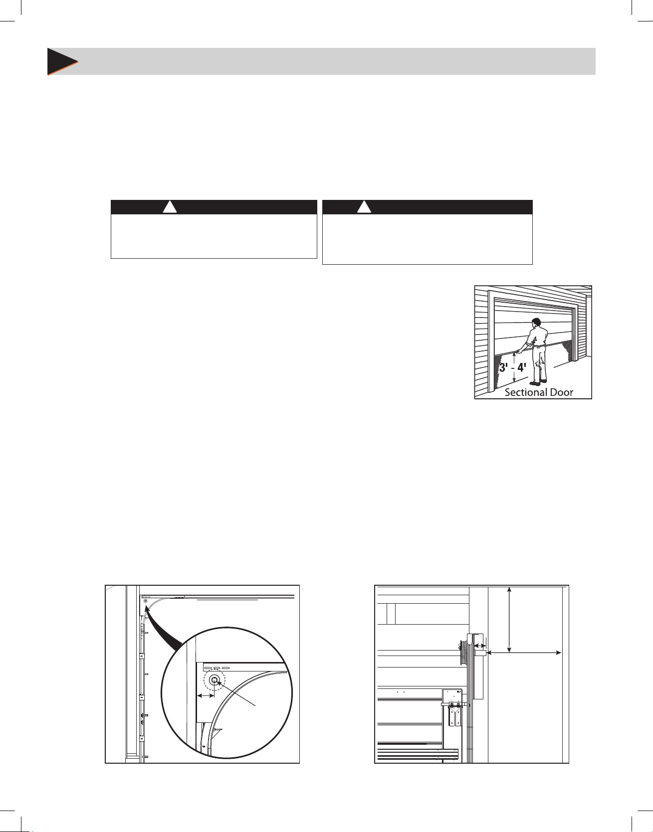
Door Inspection:
If the intended door meets the above requirements, inspect the door for proper balance and general
condition.
• Raise and lower the door manually. Door should move freely and smoothly.
• Raise door manually about 3’ to 4’ feet from oor and let go.
Door should remain stationary or slowly
drift closed. FIG.A.
If door opens or closes rapidly, CONTACT A TRAINED DOOR SYSTEM TECHNICIAN to have your door springs
serviced.
• Disable or remove all locks and ropes attached to the door.
• Monitor the end of the torsion bar while the door is raised and lowered. It is important that there is no
FIG. A
noticeable movement up and down or side to side, if there is, CONTACT A TRAINED DOOR SYSTEM
TECHNICIAN, otherwise opener reliability will be signicantly reduced.
Critical Measurements:
This opener can be installed left or right handed. Critical measurements must be taken to ensure this opener will t the intended
door.
This opener will directly couple onto torsion shafts, solid or tubular, of 1 inch in diameter with or without a keyway. (X)
Measure the distance between the torsion bar centerline to the wall. This dimension must be between 2-1/2” and 6”. (A)
The torsion bar shaft must protrude no less than 2-1/4” from bearing plate. (B)
A standard 115 VAC grounded electrical outlet will be required within 5 feet of the bottom of the opener.
Torsion bar centerline to the ceiling must be at least 2-1/4” for clearance. (C) Note: Headroom required is less than smallest standard
drum (400.8).
End of torsion shaft to side wall clearance must be at least 7 in. for clearance (D)
NOTE: Alternate mounting kits are available for TorqueMaster® and Indirect Chain Couple. See accessories page for more information.
C
B
SIDE VIEW
4
D
FRONT VIEW
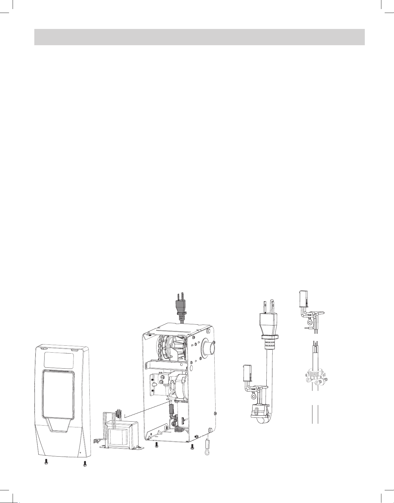
PRE-INSTALLATION CONSIDERATIONS (INPUT POWER WIRING OPTIONS)
If a 115V power outlet is not available within 5 feet from bottom of the opener when mounted to door, as an
option the Alternate Low Voltage Power Kit may be used (See section 9).
This task should be performed prior to mounting opener. Fully read and understand the instructions that
accompany the kit before proceeding.
PERMANENT WIRING SHOULD BE COMPLETED BY A TRAINED ELECTRICIAN ONLY:
1. Remove two screws from bottom of cover and remove main opener cover/circuit board assembly.
2. Unplug wire harnesses from main board.
3. Unplug input power cable connector from transformer input.
4. Remove transformer from chassis.
5. Remove strain relief and pull power cable from opener.
6. Install opener per instructions on pages 6 through 9.
7. Cut power cable wires and strip insulation from power cable input harness connector end.
• All wire connections must be made INSIDE CHASSIS and there must be at least 3” of new power supply line wire inside chassis.
• Check local code for the use of conduit or other protective material.
• Conduit, ttings/strain relief, and wire nuts are not provided.
8. Install 1/2in. NPT or other suitable connector into chassis. (Adhere to local electrical code(s) and regulations)
9. Connect permanent power input cable to harness wires using approved connectors or wire nuts (Adhere to local electrical
code(s) and regulations)
10. Install ground connector to permanent power cable ground wire.
11. Install ground screw and power cable ground onto chassis.
12. Plug power input harness into transformer harness.
13. Install transformer.
14. Ensure input power cable and connections do not interfere with internal moving components.
15. Plug all harnesses into main control board and install cover assembly.
16. DO NOT APPLY POWER AT THIS TIME.
17. Continue installation starting on page 10.
Remove
from
chassis
Power Input
Harness
Wire Nut
Connections
Strain Relief
Cable Connector
External
power cable
5
Bottom Corner Bracket
n
!
!
!
!
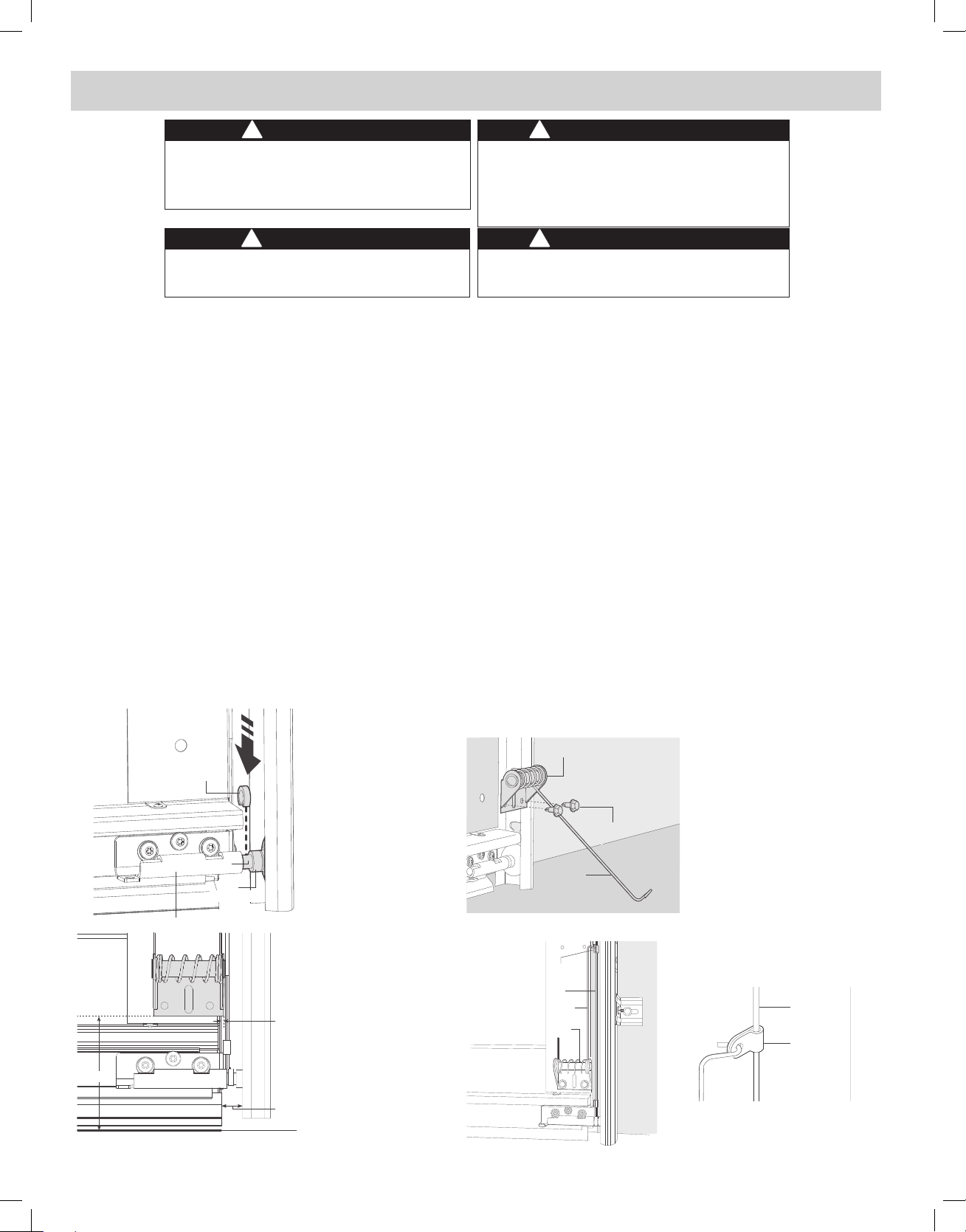
INSTALLING CABLE KEEPERS
WARNING
Operating a door with frayed or broken counterbalance lift
cables can result in severe or fatal injury.
Contact a qualied door service company to replace frayed
or broken cables before installing cable keepers.
WARNING
Do not attempt to loosen or remove bottom corner brackets.
They are under extreme spring tension and can cause
severe or fatal injury.
Faire fonctionner une porte avec des câbles de levage à
contrepoids elochés ou cassés peut entraîner des blessures
graves, voire mortelles.
Contactez une société qualiée en réparations de portes pour
remplacer les câbles elochés ou cassés avant d’installer des
protège-câbles.
N’essayez pas de desserrer ou de retirer les supports en
cornière inférieurs. Ils sont soumis à une tension de ressort extrême et peuvent causer des blessures graves, voire mortelles.
AVERTISSEMENT
AVERTISSEMENT
1. Carefully inspect the counterbalance lift cables on the door. If they are worn, frayed or broken, contact a qualied door service
company to replace the counterbalance lift cables before installing the cable keepers.
2. Push spacer onto the shaft between the short stem track roller and the bottom corner bracket. Use an additional spacer if
needed to achieve a minimum of 1/2” clearance.
3. If there is less than 1/2” clearance, loosen the lag screws attaching the track to the wall and adjust the track for the 1/2”
clearance. Re-tighten the lag screws.
4. Position the right hand (black) cable keeper assembly directly above the garage door bottom corner bracket.
5. The cable keeper assembly must extend 1/8” past the end of the door section. Ensure there is no more than 4-1/2” from the
bottom edge of the door to bottom of cable keeper.
6. IMPORTANT: RIGHT AND LEFT HAND IS ALWAYS DETERMINED FROM INSIDE THE BUILDING LOOKING OUT.
7. Fasten the cable keeper assembly with (2) 1/4” - 22 x 11/16” self drilling screws (wood doors will use (2) 1/4” x 1” lag screws).
Once the cable keeper assembly is secured to the bottom section, place the plastic sleeve over the counterbalance lift cable and
then rotate the cable keeper arm upward and attach it to the plastic sleeve.
8. Repeat the same process for the left hand (Red) cable keeper assembly.
NOTE: It is recommended that wood doors be pre-drilled with 1/8” pilot holes prior to fastening.
IMPORTANT NOTE: Operate door manually full open to full close and watch keeper to ensure that it does not contact door track.
Adjust as necessary.
Cable Keeper
Assembly
Spacer
(2) 1/4” -20 x 11/16”
Self Drilling Screws
Shaft
Cable Keeper Arm
Track Roller
Plastic
sleeve
1/8”
Counterbalance
lift cable
Cable
keeper arm
Cable keeper
assembly
installed
Counterbalance
lift cable
Plastic
sleeve
4-1/2” Max
1/2” Mi
FLOOR
6
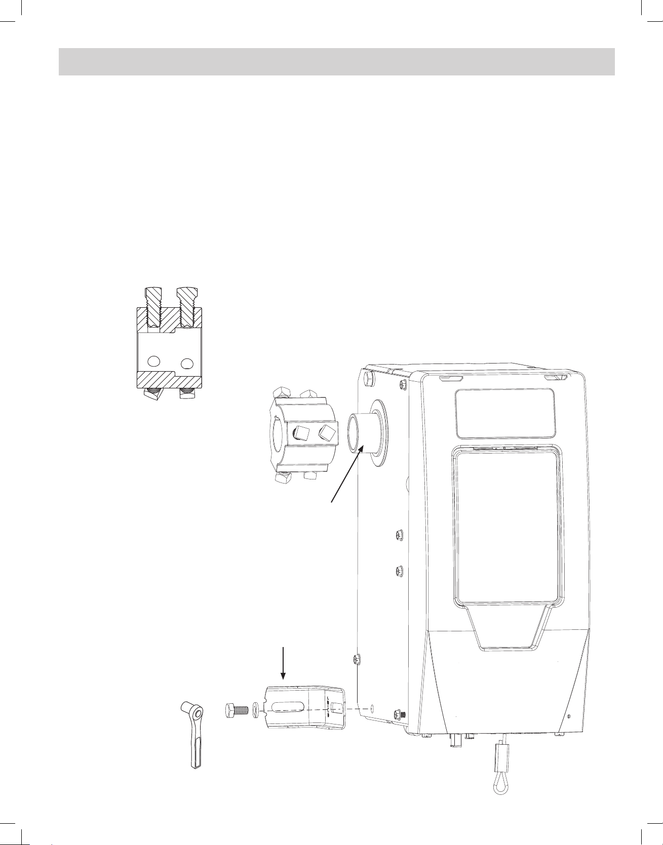
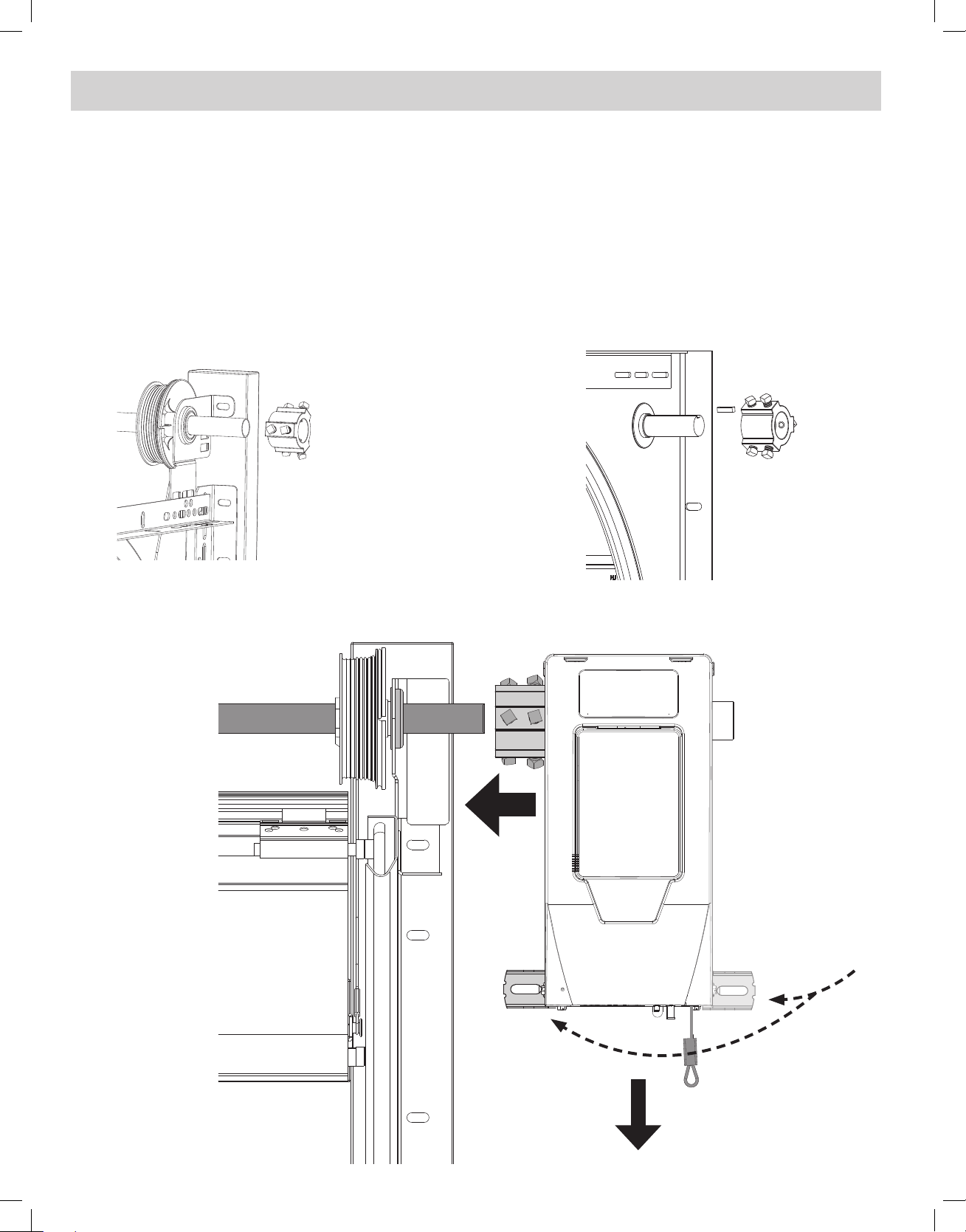
INSTALLING THE OPENER
1) CLOSE DOOR.
2) Remove bolt and lock washer (A) from powerhead chassis and loosely install mounting bracket from kit
bag on desired side of powerhead. (Right Hand mount shown)
NOTE: Bracket can be mounted to opener on either side depending on mounting requirements.
3) Slide coupler (1-1/4” end) onto opener output shaft until it fully seats. (See Coupler Cross Section detail
below)
4) Tighten 3 inner set screws on coupler nger tight against opener output shaft.
NOTE: The coupler must be installed onto the opener output shaft until the coupler seats completely to the recess
inside coupler.
NOTE: Opener MUST be mounted to garage framing material. DO NOT install to particle board or
drywall.
NOTE: Alternate installation method: If dimension D (page 4) is less than 8”, install coupler onto door
shaft rst.
Opener Output
Door Shaft - 1”
Shaft - 1-1/4”
Coupler Cross Section
A
Opener
Output
Shaft
Opener
Mounting
Bracket
7/16”
SOCKET
7
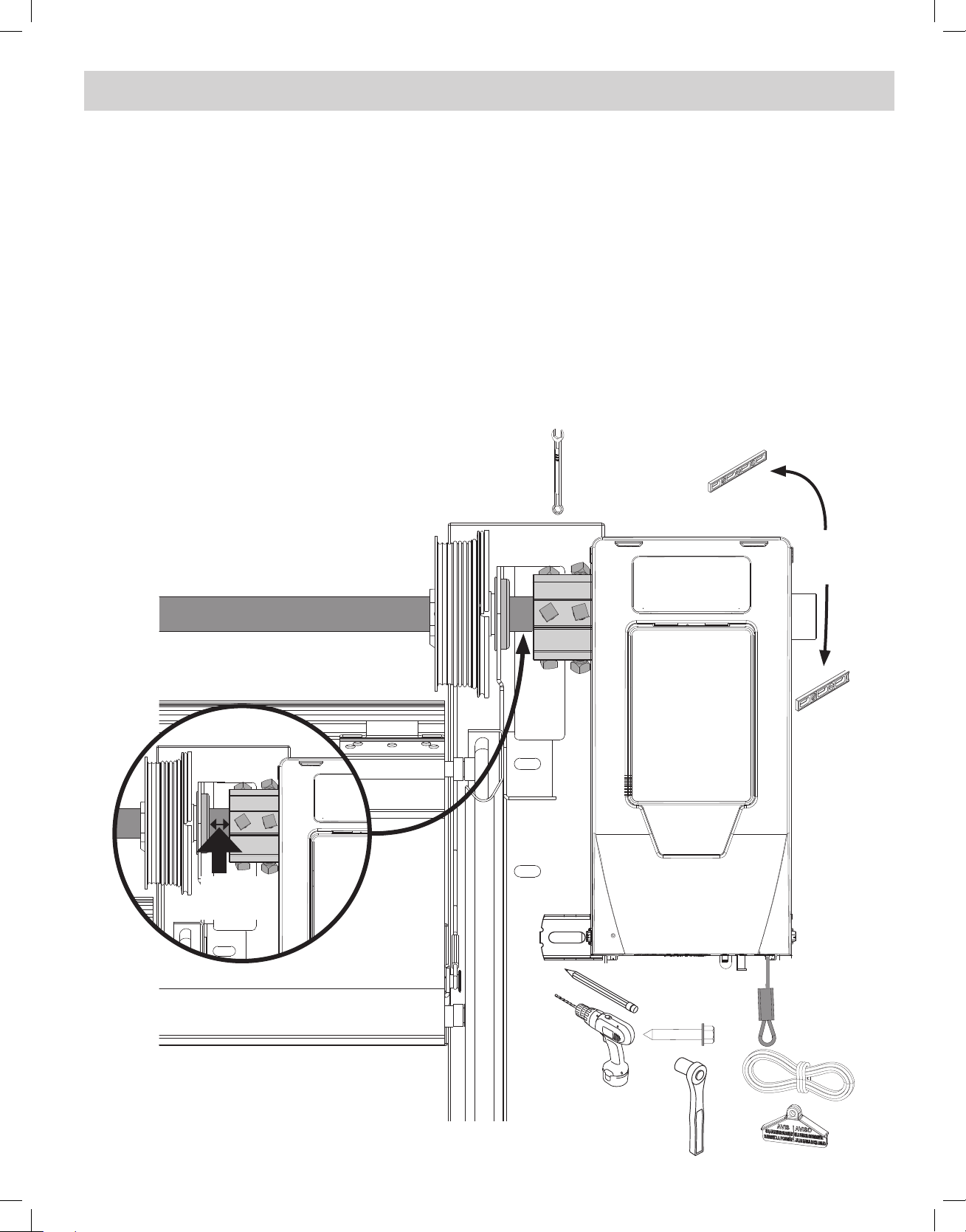
INSTALLING THE OPENER (CONT’)
5) Mount opener to door shaft.
If the door shaft is NOT keyed, slide opener assembly onto door shaft and tighten setscrews nger tight.
If the door shaft IS keyed, insert provided key into either keyway. Pull emergency release cable at the bottom
of the opener to allow free rotation of the output shaft to “clock” the keyways together.
Tighten set screws onto door shaft nger tight.
NOTE: The mounting of this opener to the door shaft is designed so the door shaft will slide through the coupler
and enter the hollow output shaft of the opener up to 3 -3/8” (there is a stop pin located in the center of the
opener output shaft).
SOLID OR HOLLOW
DOOR SHAFT NO KEY
CABLE DRUM
DOOR TORSION SHAFT
DOOR
SOLID KEYED
DOOR SHAFT
OPENER REMOVED FOR CLARITY
RIGHT HAND INSTALL SHOWN
Bracket can be
mounted to
opener on either
side depending
on mounting
requirements.
RELEASE CABLE
8
INSTALLING THE OPENER (CONT’)
6) Mount opener to wall.
Level and square opener. NOTE: Vertical lift openers will not be level.
Mark mounting bracket hole position, pre-drill a 3/16” pilot hole and install lag screw and fully tighten.
Add 1 full turn to hollow tube or 1/2 turn for solid shaft on each coupler set screw in 1/4 turn increments after
contacting door and opener shaft surfaces. DO NOT tighten set screws into an empty keyway.
Leave at least a 1/4” gap between coupler and door shaft bearing.
Tighten mounting bracket bolt to opener.
Pull emergency release cable and manually operate door to inspect for binding.
Tie RED emergency release cord to cable loop and tie release handle to cord approximately 5 feet from oor.
NOTE: Ensure all COUPLER BOLTS are secured prior to tightening mounting bracket bolt.
NOTE: Opener MUST be mounted to garage framing material. DO NOT install to particle board or
drywall.
The instructions above are provided using standard wood framing and bracing. Additional bracing may be
required for this installation.
Hardware for masonry or steel construction is not provided.
PRO TIP: Use 3/8” - 8 point socket and
ratchet to secure square coupler bolts in
tight clearance situations.
7/16”
WRENCH
Level &
Square
Opener
At least
1/4” Gap
3/16”
Bit
7/16”
SOCKET
9
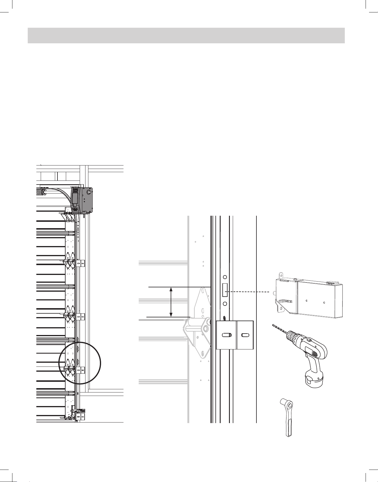
INSTALLING THE DOOR LOCK
Door lock prevents manual door operation and is important for garage security
Door lock should be installed no more than 10 feet away on the opener side of the door if
possible.
1. Mount door lock onto door track above a roller on the second or third door panel from the oor.
If mounting position does not line up with pre-punched door lock bar cutouts as shown below:
• Remove template from the back page of the owners manual.
• Apply template to the door track where the center 7/16” hole is approximately 3 inches above the door
roller on the 2nd or 3rd door panel.
• Drill two 9/32” holes for mounting and one 7/16” hole if using template. De-burr holes if required.
2. Position door lock and install two 1/4” X 9/16” track bolts and nuts. Install track bolt on inside of door track
facing outward.
Approx. 3”
9/32”
7/16”
Bit
7/16”
SOCKET
10
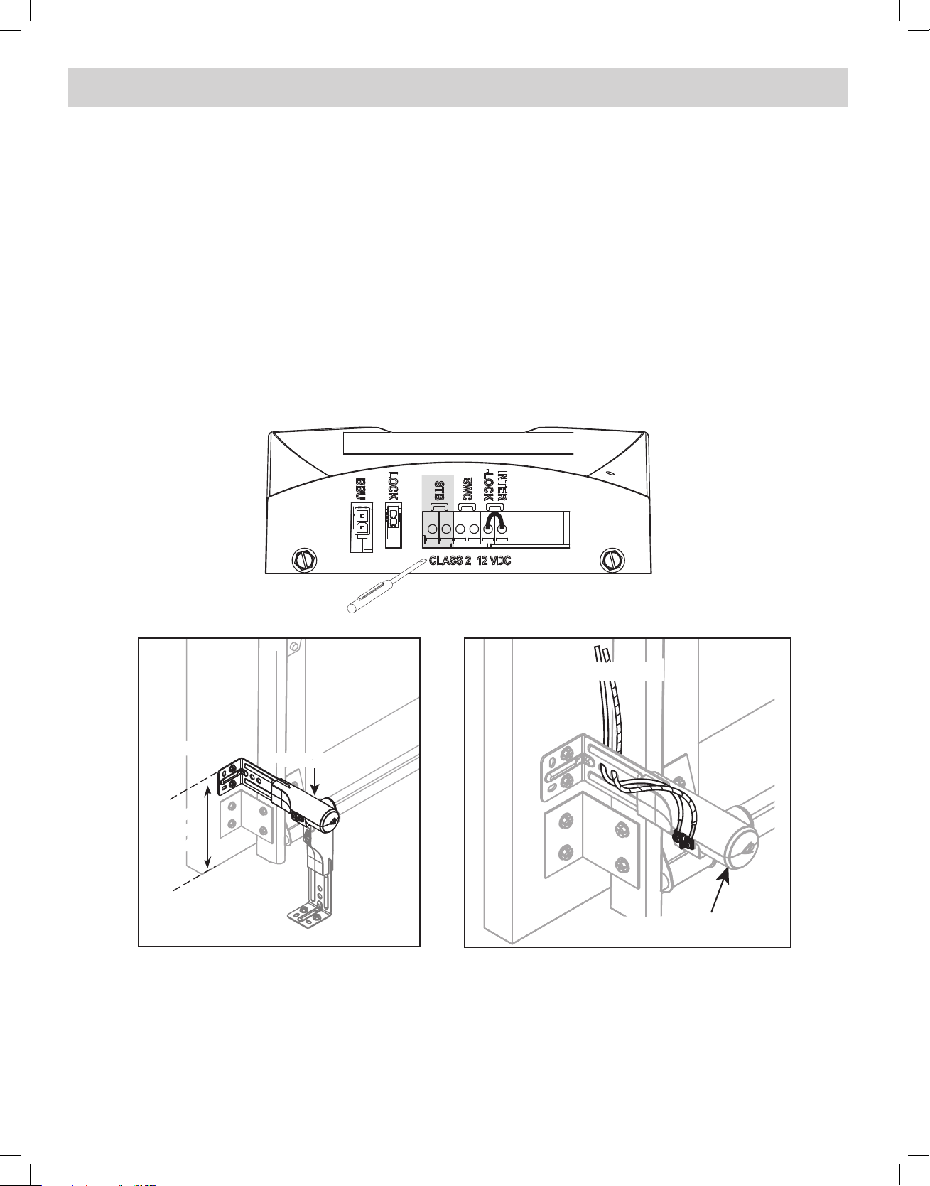
4
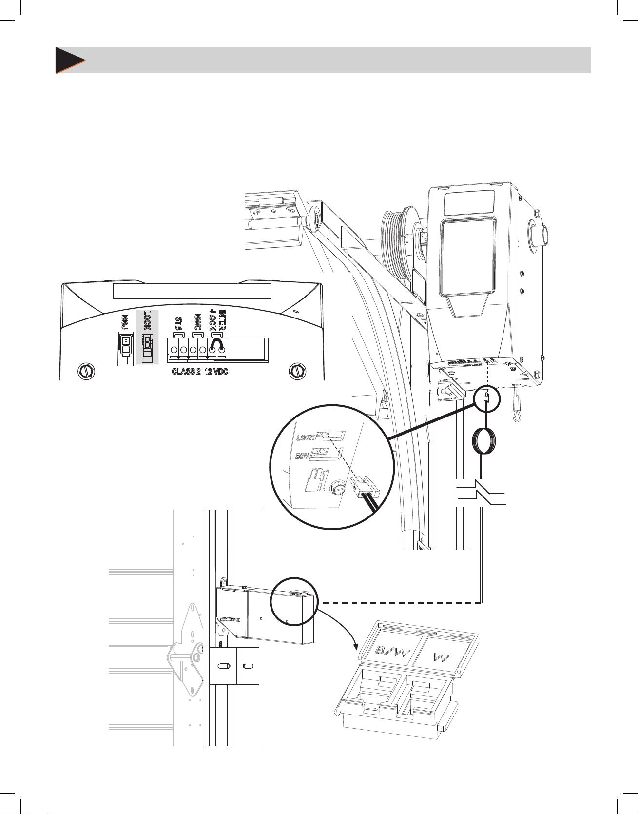
WIRE THE OPENER
Wire Door Lock
1. Plug door lock harness into the LOCK plug on bottom of opener. Insert plug in correct direction (SEE INSET)
2. Run wire down the wall to the DOOR LOCK and secure with supplied wire staples. NOTE that DOOR LOCK
wires are polarity sensitive.
3. Cut o excess wire, strip 1/4” of insulation and attach to bottom connectors on DOOR LOCK.
4. Install WHITE wire to W terminal and STRIPED wire to B/W terminal.
ALL WIRE CONNECTIONS LOCATED AT BOTTOM OF OPENER
Door Lock Plug
Door Lock Wire Connections
11
WIRE THE OPENER (CONT’)
Install and Wire Safe-T-Beams® (STB)
1. Position Safe-T-Beam® (STB) Transmitter and Receiver on each side of garage door 5"- 6" above oor. Face
the lenses towards each other.
2. Mark bracket mounting holes; drill 3/32" pilot holes and secure with 1/4" x 1-1/4" lag screws (provided) into
wood. If mounting into concrete or block, other fasteners are required and are available at leading retail
stores.
3. Route 2 lengths of supplied wire from powerhead, down to one sensor and along the header and down the
side of the door to the other sensor. Secure the wire to the walls using the insulated staples.
4. On the powerhead: Remove 1/4" insulation from both sets of white and striped wire. Twist two white wires
together. Using a small at head screwdriver, press in the orange tab at one STB terminal and insert the
wires. Twist the two striped wires together and insert into the other STB terminal. NOTE that STB wires are
not polarity sensitive.
5. At each sensor, remove 1/4" insulation from the white and striped wires and secure in each screw terminal.
Wall mount
Wall mount
6” max
6” max
5” min
5” min
above oor
above oor
Floor mount option
PHOTOCELL (STB)
PHOTOCELL (STB)
To powerhead
Transmitter/Receiver
12
 Loading...