

Overhead door CD, CDB Owner's Manual

CD Series
¤
CDB Series
3507635556
Automatic
Chain Drive/Belt Drive
Garage Door Operator
System
Complete with Remote Control and
SERIES II Electronics
Operator MUST be installed with the included SERIES II Wall Control!
Self-diagnostic Electronic Sensory Protection System (SAFE-TBEAM SYSTEM) MUST Be Installed To Close Door!
Owner’s Manual
SAVE FOR FUTURE REFERENCE
Customer Service
CALL: 1-800-929-3667
OR VISIT WWW.OVERHEADDOOR.COM
AUTOMATIC GARAGE DOOR OPERATOR SYSTEMS
HANG MANUAL NEAR YOUR WALL CONTROL
TABLE OF CONTENTS
SECTION PAGE
SAFETY INFORMATION . . . . . . . . . . . . . . . . . . . . . . . . . . . . . . . . . . . . . . . . . . . . . . 2-4
PARTS IDENTIFICATION . . . . . . . . . . . . . . . . . . . . . . . . . . . . . . . . . . . . . . . . . . . . . . 5-6
ASSEMBLY
1 OPERATOR ASSEMBLY . . . . . . . . . . . . . . . . . . . . . . . . . . . . . . . . . . . . 10-11
1A Channel and Power Head Assembly . . . . . . . . . . . . . . . . . . .10
1B Rail and Power Head Assembly . . . . . . . . . . . . . . . . . . . . .10-11
INSTALLATION
2 DETERMINE DOOR TYPE AND MOUNTING METHOD . . . . . . . . . . . 11
2A Installation on Track Guided Doors . . . . . . . . . . . . . . . . 12-14
2B Installation on Trackless Doors . . . . . . . . . . . . . . . . . . . . 15-17
3 SAFE-T-BEAM®(STB) SYSTEM INSTALLATION . . . . . . . . . . . . . . . 18-19
Self-diagnostic “STB”System Troubleshooting . . . . . . . . . . . . 19
4 WALL CONTROL INSTALLATION . . . . . . . . . . . . . . . . . . . . . . . . . . . . . . . 20
5 CONNECT OPERATOR TO POWER . . . . . . . . . . . . . . . . . . . . . . . . . . . . . 21
6 MAIN LIMIT SWITCH SETTINGS . . . . . . . . . . . . . . . . . . . . . . . . . . . . . . . 22
OPERATION
7 FORCE ADJUSTMENT . . . . . . . . . . . . . . . . . . . . . . . . . . . . . . . . . . . . . . . . 23
Contact Reverse . . . . . . . . . . . . . . . . . . . . . . . . . . . . . . . . . . . . . . . . . 23
8 FINE LIMIT SWITCH ADJUSTMENTS . . . . . . . . . . . . . . . . . . . . . . . . . . . 24
9 REMOTE CONTROLS . . . . . . . . . . . . . . . . . . . . . . . . . . . . . . . . . . . . . . 24-25
10 BATTERY & VISOR CLIP INSTALLATION . . . . . . . . . . . . . . . . . . . . . . . . 25
11 LIGHT BULB AND LENS INSTALLATION . . . . . . . . . . . . . . . . . . . . . . . . 26
MAINTENANCE . . . . . . . . . . . . . . . . . . . . . . . . . . . . . . . . . . . . . . . . . . . . . . . . . . . . . . .27
TROUBLESHOOTING GUIDE . . . . . . . . . . . . . . . . . . . . . . . . . . . . . . . . . . . . . . . . . . 28
WIRING DIAGRAM . . . . . . . . . . . . . . . . . . . . . . . . . . . . . . . . . . . . . . . . . . . . . . . . . . . 29
ACCESSORIES . . . . . . . . . . . . . . . . . . . . . . . . . . . . . . . . . . . . . . . . . . . . . . . . . . . . . . . .30
WARRANTY 32

PRE-INSTALLATION CHECK LIST
FOR HELP—1-800-929.3667 OR OVERHEADDOOR.COM
Things to consider if you are planning to “do-it-yourself.”
Whether you are replacing an existing garage door operator or installing an operator in your garage for
the first time, there are some pre-installation issues which need to be addressed.They are as follows:
2
mation and instructions contained herein before choosing a “Do-It-Yourself ” installation.
A
Door Dealer.
The Overhead Door Corporation recommends that you read and fully understand all infor-
ny questions should be directed to the Overhead Door Corporation or an authorized Overhead
(
The issue numbers below refer to the circled numbers in the illustrations on page 3.
Check your ceiling where the power
head of your new unit will be mounted. Plan
1
ho
w you will be mounting the power head.It is possible that ceiling joists may not be in the exact position needed with respect to the garage door operator.In any case, it may be necessary to add an additional bracket and
new door operator kit).
Check the wall directly above the garage
door
2
be securely fastened to this wall. Insure that the
structure will provide a strong mounting location.
3
from obstruction and has a wood surface a
brackets may also be attached to concrete if necessary but extra tools and special fasteners (not supplied) will be required.
bracket adapters are available through your local
O
verhead Door Dealer.
. The door operator’s header bracket must
Check to see if the mounting location
for the Safe-T-Beam
vailable for attaching the STB brackets
fasteners (not included with your
®
System (STB)is clear
. The
NOTE: 1-1/2" “STB”
You need a 110-120 Volt power supply
available
5
standard electrical outlet, is one available? The outlet
should be no more than about 3 feet from the power
head once it is mounted. ( The cord is 4 ft. in length.) SEE
WARNING BELOW.
To avoid damage to your door and/or
6
operator, make sure you disable any door locks
prior to installing your operator
Insure that your door is properly balanced
7
and moving freely. SEE WARNING BELOW.
. If you plan to plug the unit into a
)
.
Is your garage door made of
light-weight steel, aluminum, fiberglass or
4
glass panels
added to these type doors. If this is the case, please
contact the door distributor or manufacturer so
that they can furnish you with a “bracing kit.”
DO NOT USE EXTENSION CORD! Extension
cords can cause dangerous overheating conditions.
DO NOT USE PORTABLE GENERATOR! This
product is designed to operate on standard
house current. Do not use alternate power
supplies.
? Additional support bracing must be
WARNING
(NOT SHOWN) If your garage does not have
a separate entry door, you might want to consider
8
an emergency r
your garage door. See page 30.
If your door sticks, binds, or is out of
balance, have it adjusted by a professional. Door
springs, cables, pulleys, brackets and associated
hardware are under extreme tension and
can cause serious injury or death.
elease kit (GER-2)for installation on
WARNING
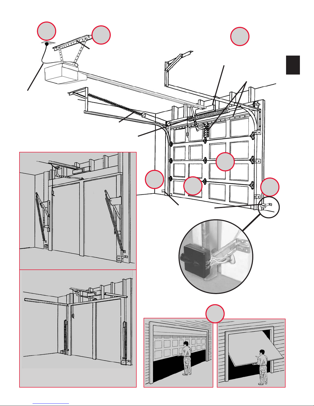
TYPICAL SECTIONAL DOOR INSTALLATION
5
36” POWER CORD
TO
120V GROUNDED
OUTLET
1
TYPICAL
SUPPORT
BRACKET
EXTENSION SPRING
OR
TORSION SPRING
3
6
2
ADDED
HEADER BRACKET
MOUNTING BOARD
3
BRACES
4
3
TYPICAL (TRACKLESS)
1-PIECE DOOR INSTALLATION
SAFE-T-BEAM
®
7
TYPICAL (TRACK GUIDED)
1-PIECE DOOR INSTALLATION
SECTIONAL DOOR
ONE-PIECE DOOR

SAFETY INFORMATION OPERATOR INSTALLATION
Garage doors are large, heavy objects that move with the help of springs under
high tension and electric motors. Since moving objects, springs under tension,and
electric motors can cause injuries, your safety and the safety of others depend on
4
you reading the information in this manual. If you have questions or do not understand the information presented,call your nearest service representative
In this section and those that follow,the words Danger
used to emphasize important safety information.
The word:
DANGER means that severe injury or death will result from failure
to f
WARNING means that severe injury or death can result from failure
t
CAUTION means that property damage or injury can result from failure
t
The word NOTE is used to indicate important steps to be followed
ortant considerations.
or imp
POTENTIAL
HAZARD
MOVING
DOOR
ELECTRICAL
SHOCK
HIGH
SPRING
TENSION
SAFETY FEATURES
OVERVIEW OF
POTENTIAL HAZARDS
, Warning, and Caution are
ollow instructions.
o follow instructions.
o follow instruction.
EFFECT PREVENTION
Keep people clear of opening while door is
WARNING:
Can Cause
Serious Injury
or Death
WARNING:
Can Cause
Serious Injur
or Death
WARNING:
Can Cause
erious Injury
S
or Death
moving.
Do Not allow children to play with the door
operator.
Do Not operate a door that jams or one that has a
broken spring.
Turn off power before removing operator cover.
When replacing cover, make sure wires are not
pinched or near moving parts.
y
Operator must be properly grounded.
Do Not try to remove, repair or adjust springs or
anything to which door spring parts are fastened,
such as, wood blocks, steel brackets,
cables or other like items.
Repairs and adjustments must be made by a
trained service person using proper tools and
instructions.
(
varies by model
)
IMPORTANT
INSTALLATION
INSTRUCTIONS
WARNING
WARNING
:
:
To reduce the risk of
severe injury or death:
1. READ AND FOLLOW ALL SAFETY, INSTALLATION AND
OPERATION INSTRUCTIONS. If you have any questions or
do not understand an instruction, call your service
representative.
2. Do Not install operator on an improperly balanced door. An
improperly balanced door could cause severe injury.
Repairs and adjustments to cables, spring
assembly,and other hardware must
be made by a trained service person using
proper tools and instructions.
3. Remove all ropes and disable all locks connected to the
door before installing operator.
4. Install door operator 7 feet or more above the floor. Mount
the emergency release knob 6 feet above the floor.
5. Do Not connect the operator to the source of power until
instructed to do so.
6. Locate the control button:
• Within sight of door.
• At a minimum height of 5 feet,so small children cannot
reach it.
• Away from all moving parts of the door.
7. Install the entrapment WARNING label next to the wall button or console. Install the emergency release tag on, or
next to, the emergency release
8. The operator must reverse when the door contacts a 1-1/2
inch high object on the floor at the center of the doorway.
This is about the size of a 2” x 4” board laid flat.
Safe-T-Beam®(STB) Non-Contact Reversing System Places an
invisible beam across door opening that reverses the door during down travel to the fully open position if anything
passes through beam.
Safe-T-Reverse
®
Contact Reversing System
Automatically stops and reverses a closing door within 2 seconds of contact with an object.
Safe-T-Stop
®
Timed Reversed System Automatically
opens a closing door,if door does not close within 30 seconds.
®
Force Guard
Control Used to set
the force required for opening and closing door. For maximum safety, set the minimum force required to fully open and
close door.
Automatic Lighting System
One or two light bulbs (depending on model) up to 100 Watts max. each are used for safer entries and exits.The light
tur
ns on when door is activated and automatically turns off 4.5 minutes later.
Manual Emergency Release
Allows the garage do
or to be opened or closed manually for emergencies or maintenance.

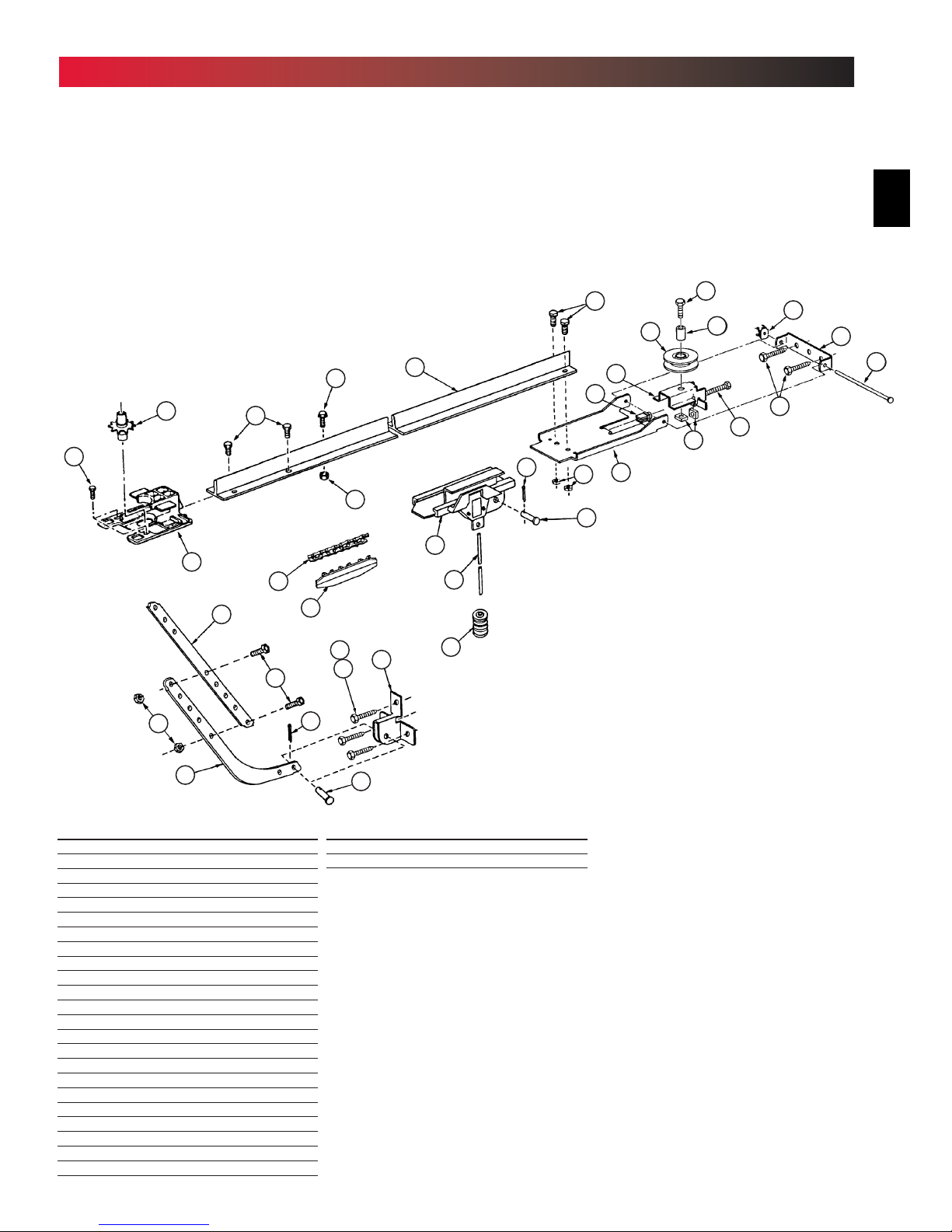
PARTS IDENTIFICATION
106
105
12 5
FOR HELP—1-800-929.3667 OR OVERHEADDOOR.COM
5
124
10 4
101
100
NOTE: Accessories vary by model.
FASTENERS -
Shown full size. See Parts List for description.
69
Bolt, #10-24 x 1/2”
112
Bolt, 5/16”-18 x 1/2”
127
Phillips Hex Head Screw,No. 10 x 1-1/4”
79
96
91
92
90
126
1/4”-20 x 3/4”
rilling Screw
Self-D
Bolt, 3/8”-16 x 7/8”
Nut, 3/8-16
remotes
vary by model
12 8
10
9
103
Insulated Staple
Wall Console Screw
Pan Head Screw #6 x 1-1/4”
Pan Head
Phillips Screw
No. 8 x 5/8”
81
82
Lag Screw,1/4” x 2”
OR
Speed Nut
Cold Head Pin
89
levis Pin
C
Cotter Pin
Hex Head Screw
No. 8 x 3/4”
PARTS IDENTIFICATION
FOR HELP—1-800-929.3667 OR OVERHEADDOOR.COM
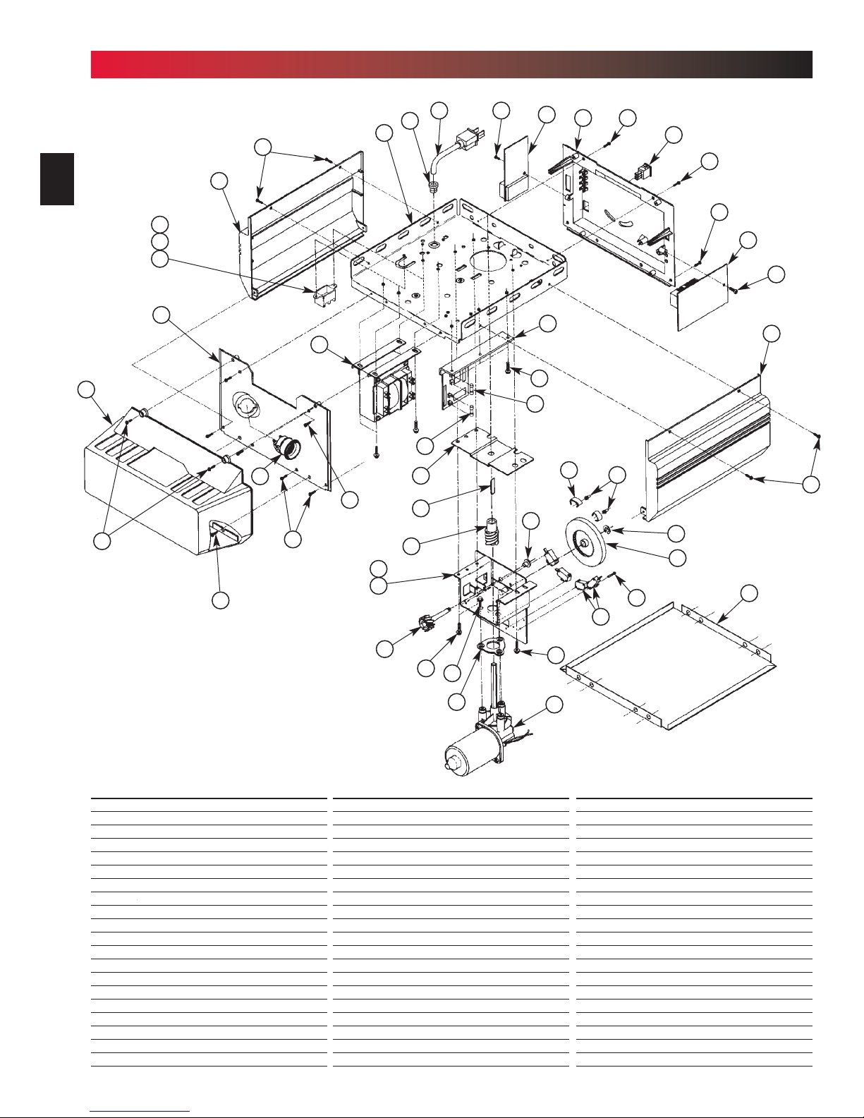
Phantom Power Head (DC)
6
15
14
12
2
1
10
3
13
9
12
11
20
12
27
25
6
5
4
23
24
36
35
19
34
22
26
16
21
39
7
12
17
12
11
18
19
3
28
40
29
38
37
8
12
Combined Parts List
Item Part Name
1 Lens
2 Front Cover
3 Side Cover (by series/model)
4 Top Plate Assembly
5 Strain Relief
6 Cord & Plug Assembly
7 Component Panel (by series/model)
8 Bottom Cover
9 Screw,#8 x .75 Phil Hx Hd/W Sf Tap
10 Screw,#8 x .62 Phil Pan Hd/W Sf Tap
11 Screw,#8 x .50 Slt Hx Hd/W Sf Tap
12 Screw,#8 x .38 Slt Hx Hd/W Sf Tap
13 Light Socket (by series/model)
14 Terminal Block & Lug
15 M.O.V. Assembly
16 Receiver Assembly
17 Limit Set Switch
18 Sequencer Assembly
19 Screw,#6 x .38 Slt Hx Hd/W Sf Tap
20 Transformer Assembly (by series/model)
33
26
32
31
Item Part Name
21 Rectifier Board Assembly
22 Fuse (F1), UL
23 Fuse (F2), UL
24 Limit Gear Shroud
25 Motor Bracket
26 Screw,#10 x 3/8” HH
27 Limit Plate/Pin Assembly
28 Limit Switch
29 Screw,#4-40x 5/8”Slot HH w/Wshr,SfTap
30 Motor Assembly
31 Motor Adapter Plate
32 Screw,1/4"-20 x 1/2" Slt HH w/Wshr
33 Limit Worm Gear
34 Limit Gear Bushing
35 Limit Worm Drive
36 Limit Worm Shim
37 Limit Wheel
38 Retaining Ring
39 Limit Cam
40 Limit Pinion, 8 tooth
26
30
Item Part Name
41 Capacitor
42 Capacitor Clamp
43 Screw,#10-24 x 1/2”, Slot HH Sf-Tap
44 Nut, #10-32,Hex Serrated Flange
45 Circuit Board
46 C.B. Bracket
47 Circuit Board Mount
48 Screw,#10-16 x 5/8”, HH Sf Tap
49 Top Gear Housing
50 Middle Gear Housing
51 Bottom Gear Housing
52 Drive Shaft Bushing
53 Drive Thrust Washer
54 Drive Shaft
55 1/2” Retaining Ring
56 Main Drive Worm Gear
57 Optical Interrupt Wheel
58 Motor Flanged Bushing
59 Motor Thrust Washer
60 Poly Thrust Washer
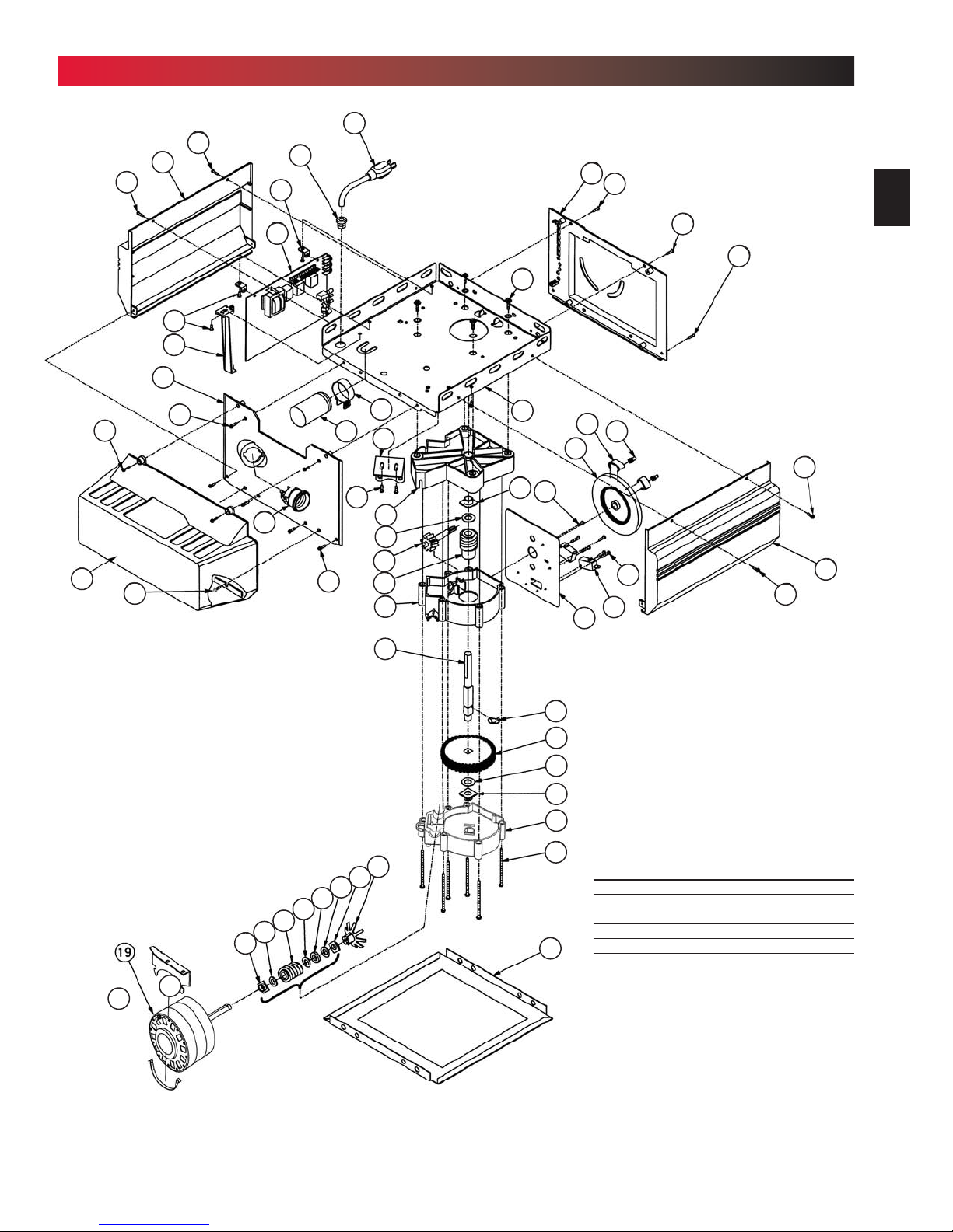
PARTS IDENTIFICATION
FOR HELP—1-800-929.3667 OR OVERHEADDOOR.COM
Legacy Power Head (AC)
7
12
12
6
12
3
5
47
7
45
48
12
46
2
41
42
25
43
49
53
33
35
50
12
10
13
1
9
11
52
4
64
37
63
39
40
65
28
12
11
12
3
12
44
30
58
59
61
59
60
59
58
57
54
55
56
53
52
51
62
Item Part Name
61 Main Drive Worm
62 Screw,#8 x 3-1/8” Slot HH, Sf Tap
63 Limit Switch Plate
64 Screw,#6 x 3/8” Phillips w/Wshr, Sf Tap
8
65 Screw,#4 x 5/8”, Slot HH w/Wshr, Sf Tap
8
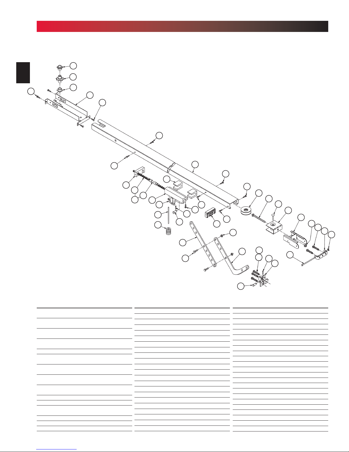
PARTS IDENTIFICATION
Channel
67
68
FOR HELP—1-800-929.3667 OR OVERHEADDOOR.COM
69
67
70
69
71
83
84
66
85
86
87
88
71
97
98
90
94
91
89
65
99
71
83
71
71
92
93
71
73
79
96
74
89
95
75
76
82
77
78
79
80
81
Combined Parts List
Item Part Name
66 Belt & Bullet Assembly - 7’6” Door
(Belt Models Only)
Belt & Bullet Assembly - 8’ Door
(Belt Models Only)
Belt & Bullet Assembly - 10’ Door
(Belt Models Only)
Belt & Bullet Assembly - 12’ Door
(Belt Models Only)
67 Sprocket Bushing
68 Sprocket, 10 Tooth - 7’6”& 8’ Doors
(Chain Models Only)
Sprocket, 12 Tooth - 10’Door
(Chain Models Only)
Drive Sprocket, 18 Tooth - 7’6” & 8’ Doors
(Belt Models Only)
Drive Sprocket - 10’ Door
(Belt Models Only)
69 Screw,#10-24 x .50 Hx Hd
70 Sprocket Bracket (Chain Models Only)
Sprocket Bracket - 7’6” & 8’ Doors
(Belt Models Only)
Sprocket Bracket - 10’ Door (Belt Only)
Sprocket Bracket - 12’ Door (Belt Only)
71 Screw,#10-24 x .38 Hx Hd/W
Item Part Name
72 Channel - 7’6” Door (128” LG )
Channel - 8’ Door (146” LG )
Channel - 10’ Door (170.75” LG )
Channel - 12’ Door (188” LG)
73 Pulley (Chain Models Only)
Pulley (Belt Models Only)
74 Carriage Bolt, 5/16”-18 x 4.0
75 Carriage Pin, 5/16”x 1.25
76 Pulley Bracket Assembly
77 End Bracket
78 Hex Flange Nut, 5/16”-18 (Chain Only)
Flat Washer (Belt Models Only)
(2) Hex Jam Nut,5/16-18 (Belt Models Only)
79 Lag Screw,1/4” x 2” Hx Hd/W
80 Header Bracket
81 Speed Nut
82 Cold Header Pin
83 Carriage Stop
84
Roller Chain-7’6”Door (Chain Only)(242.5”)
Roller Chain-8’Door (ChainOnly)(278.5”)
Roller Chain-10’Door (ChainOnly)(328.5”)
8mm Belt
90
Item Part Name
85 Chain Bullet
Belt Bullet
Belt Retainer
Screw,#6-32 x 1/2” Phil Pan Hd Slf Tap
86 Carriage Slide
87
Emerg. Release Cord-7’6”Doors (26.5”)
Emerg. Release Cord -8’-10’Doors (56.5”)
Emergency Release Cord -12’Doors(96.0”)
88 Emergency Release Knob (Red)
89 Cotter Pin
90 Clevis Pin
91 Screw,3/8”-16 x .87 Hx Hd Mach
92 Hex Nut, 3/8”-16
93 Curved Door Arm
94 Straight Door Arm
95 Door Bracket
96 Screw,1/4”-20 x 3/4” Hx Hd, Sf Tap
97 Carriage Assembly
98 Carriage Cap
99 Screw,#10-14 x 1-5/16” Hx Hd
100 Wall Console (Series II )
101 Wall Button (Series II ) (lit primary)
Wall Button (unlit secondary)
PARTS IDENTIFICATION
FOR HELP—1-800-929.3667 OR OVERHEADDOOR.COM
Rail
9
69
92
68
115
94
112
114
91
86
89
121
79
96
122
95
110
97
88
87
89
123
90
111
117
76
118
81
12 0
119
80
82
79
116
73
11
93
Item Part Name
102 Boom Support Kit (not shown)
103 Safety & Maintenance Guide
104 Emergency Release Tag (Tri-L)
105 Entrapment WARNING Label
106 Wire
110 Rail (L=112.475”)
111 Screw, 5/16”-18 x 3/4”
112 Screw, 5/16”x 1/2” HH w/Wshr
113 Pulley Support
114 Chain
115 Sprocket Saddle
116 Screw, 5/16”-18 x 2-1/4”HH
117 Bolt Retainer
118 Screw, 5/16”-18 x 1-1/8”HH
119 Large Pulley Bushing
120 Square Nut, 5/16”-18
121 Screw, 1/4”-20 1”HH
122 Hex Nut/Lockwasher, 1/4”-20
123 5/16"-18 Lock Nut
124 STB System Sensor (Green LED)
125 STB System Source (Red LED)
126 STB Mounting Brackets (2)
90
Item Part Name
127 Screw, 1-1/4”Phillips HH
128 Insulated Staples
...
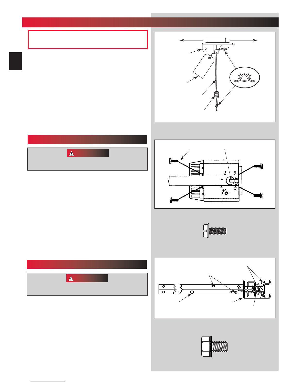
OPERATOR ASSEMBLY
1
FOR HELP—1-800-929.3667 OR OVERHEADDOOR.COM
10
OPEN BLUE PARTS BAG
Screws for attaching light cover are included in this bag.
Attach emergency release knob cord (Fig. 1-1).
1.
• Tie overhand knot in end of cord.
• Thread cord through knob so knot is inside knob.
• Thread cord through hole in carriage lever.
• Tie overhand knot in other end of cord.
Do Not cut cord until after power head is mounted.
2. Attach emergency release tag (Fig. 1-1).
• Thread wire through hole in carriage lever.
• Wrap wire around itself, tie securely.
PLEASE NOTE THE ASSEMBLY PROCEDURES ARE
DIFFERENT FOR RAIL AND CHANNEL. BE SURE TO
FOLLOW THE APPLICABLE STEPS.
CHANNEL & POWER HEAD ASSEMBLY
Do Not attempt to run power head or to set limits until
operator is fully assembled and attached to the door.
Please set aside for use later.
CAUTION
Emergency
Release
Tag
Hex Head Screws
[69]
Toward Door Toward Power Head
Carriage
Emergency
Release
Cord
Emergency
Release
Knob
Fig.1-1
“D” -Shaft and Hole
3. Place power head and channel on clean, flat surface.
4. Slide drive end of channel down over “D”-shaft on top of
p
ower head (Fig. 1-2).
• Support header end of channel level with power head.
• Slide carr
• Slide channel down “D”-shaft flush with power head.
5. Fasten channel to power head .
• Align mounting holes in front and r
• Insert and securely tighten the four (4) No.10 x 1/2”hex
head screw
NOTE: Chain inner-slide or belt bullet should remain at midtra
vel when assembling to power head to provide proper travel
when setting limits.
iage to align “D”-shaft with “D”-hole in sprocket.
ear of power head frame.
s [69].
RAIL & POWER HEAD ASSEMBLY
CAUTION
Do Not attempt to run power head or to set limits until
operator is fully assembled and attached to the door.
3. Place power head and rail on clean, flat surface.
4. Slide drive end of rail down over “D”-shaft on top
of power head (F
• Support header end of r
• Slide car
in sprocket.
• Slide rail down “D”-shaft flush with power head.
dr
ags on the rail
ig. 1-3).
ail level with power head.
riage enough to align “D”-shaft with “D”-hole
5/16” x 1/2” Hex Head Screws
[
]
112
Carriage Stop
Fig.1-2
[69]
No. 10 x 1/2” Hex Head Screw
[69]
Sprocket Saddle
Fig.1-3
[
]
112
No. 10-24 x 1/2” Hex Head Screws
“D” -Shaft and Hole
5/16” x 1/2” Hex Head Washer Screw
 Loading...