

Overhead door 780 CD, 790 CW Installation Manual
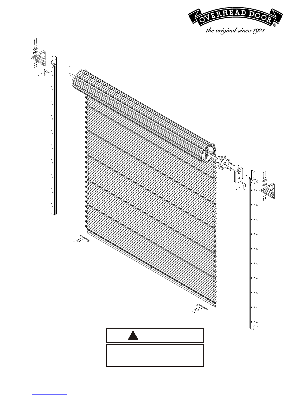
INSTALLATION INSTRUCTIONS
Series 780 CD, 790 CW
220153-0001
8/14/03
CAUTION
!!
USE PROPER LIFTING EQUIPMENT AND
CORRECT LIFTING PROCEDURES TO
AVOID INJURY.
© Overhead Door Corporation
1
SAFETY INFORMATION
OVERVIEW OF POTENTIAL HAZARDS
Overhead doors are large, heavy objects that move with the help of springs under high tension
and electric motors. Since moving objects, springs under tension, and electric motors can
cause injuries, your safety and the safety of others depend on you reading the information in
this manual. If you have questions or do not understand the information presented, call your
nearest service representative.
In this section and those that follow, the words Danger, Warning and Caution are used to
emphasize important safety information. The word:
DANGER means that severe injury or death will result from failure to follow instructions.
WARNING means that severe injury or death can result from failure to follow instructions.
CAUTION means that property damage or injury can result from failure to follow instructions.
The word NOTE is used to indicate important steps to be followed or important considerations.
POTENTIAL HAZARD EFFECT PREVENTION
Keep people clear of opening while
Door is moving.
WARNING: Can Cause
Serious Injury or Death
MOVING DOOR
WARNING: Can Cause
Serious Injury or Death
HIGH SPRING TENSION
READ THIS MANUAL CAREFULLY AND OBSERVE ALL WARNINGS WHEN INSTALLING,
OPERATING OR MAINTAINING YOUR OVERHEAD DOOR.
IMPORTANT
CHECK for shipping damage.
CHECK door against packing list to make sure door
is the same as ordered and all parts are included.
CHECK width and height of door opening against
sizes noted with shipment to assure that door will fit.
CHECK to make sure headroom and side clearances
are adequate (Figure 1).
Do Not allow children to play with
the Door operator.
Do Not operate a Door that jams or
one that has a broken spring.
Do Not try to remove, repair or adjust
springs or anything to which Door spring
parts are fastened, such as, wood blocks,
steel brackets, cables or other like items.
Repairs and adjustments must be made
by a trained service person using proper
tools and instructions.
Read these instructions completely before
attempting to install this door.
WARRANTY VOID IF DOOR IS NOT INSTALLED
ACCORDING TO INSTRUCTIONS.
DO NOT CUT OR REMOVE RETAINING BANDS
UNTIL INSTRUCTED TO DO SO.
CHECK WARNING LABELS ON DOOR FOR PROPER
INSTALLATION PROCEDURE.
2
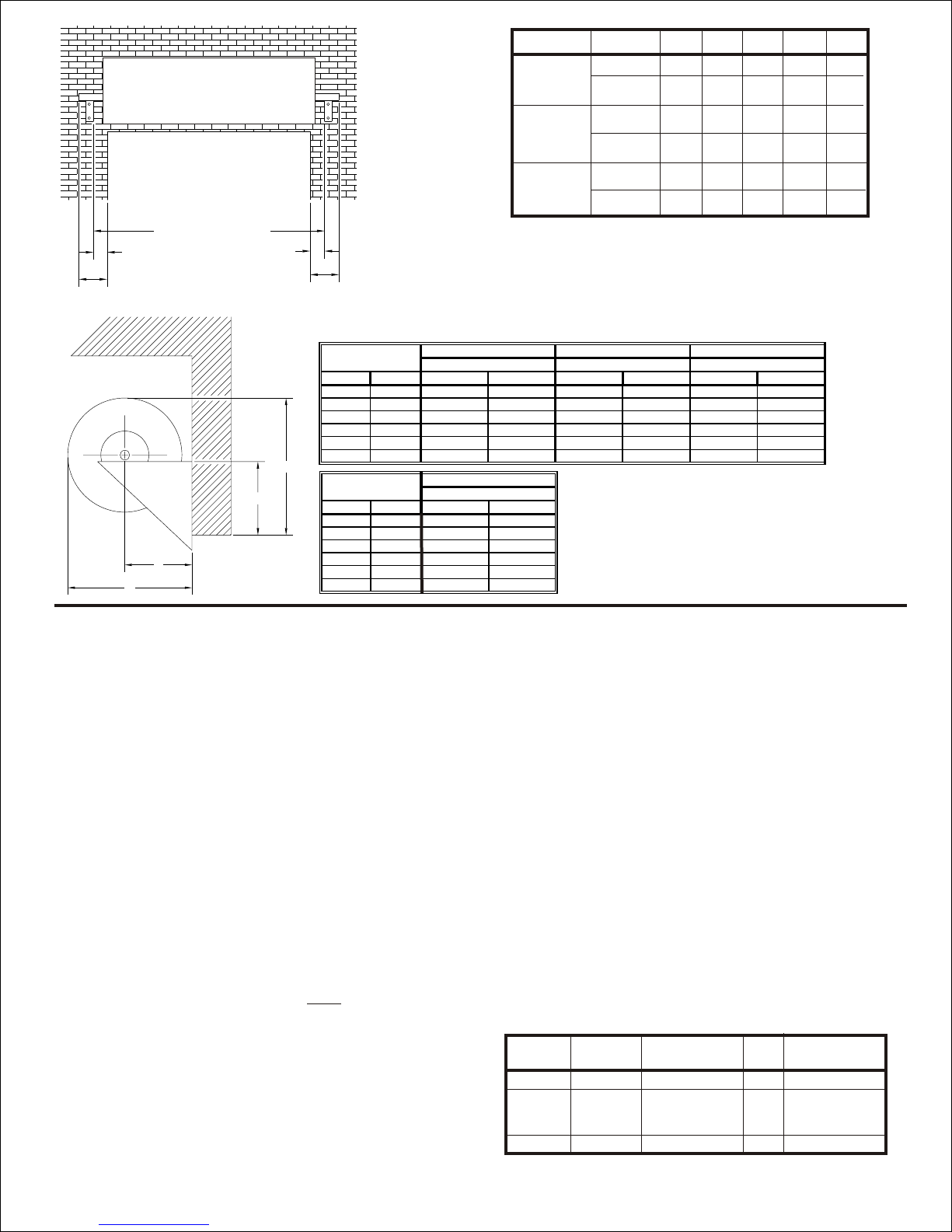
FOR REFERENCE
Over Up To
- 7' 8"
7' 9" 9' 4"
9' 5" 11' 0"
11' 1" 12' 8"
12' 9" 14' 3"
14' 4" 16' 0"
Opening Height
Recommended Minimum
20 1/4" 18 1/4"
21" 19"
21 3/4" 20 3/4"
22 3/4" 21 3/4"
23 1/4" 22 1/4"
24 3/4" 23 3/4"
B
Head Room
Over Up To Recommended Minimum Recommended Minimum Recommended Minimum
- 7' 8" 10" 8" 9 1/8" Same 18 1/8" Same
7' 9" 9' 4" 10 1/2" 8 1/2" 9 1/8" Same 18 3/8" Same
9' 5" 11' 0" 11" 10" 10 1/4" Same 19 3/4" Same
11' 1" 12' 8" 11 1/2" 10 1/2" 10 1/4" Same 20 1/4" Same
12' 9" 14' 3" 12" 11" 10 1/2" Same 20 1/2" Same
14' 4" 16' 0" 13" 12" 10 1/2" Same 21" Same
Opening Height
H J A
Head Plate Height Axle Setting Back Room
DRIVE END
Operation
Push Up
Reduced
Chain Drive
Door Type
790
780
790
780
C*
10“
10“
10“
10“
D*
10“
10“
10“
10“
F**
6“6“
4“
6“
8“
G
12“
8“
10“
12“
E
4“
4“
4“
OPENING WIDTH + G
E
C
F
D
Figure 1
B
H
J
A
NOTES
Bracing may be required to prevent
light weight building jambs from twisting.
INSTALLATION
1. Locate headplates per dimensions F, (or approximately
5” above top of guide, if headroom allows)
E, H and G (Figure 1).
2. Hold headplates in mounting position. Using a water
level, check to make sure tops of headplates are level.
Mark mounting hole locations on header. See Table 1
for supplied fasteners.Thru-bolts are recommended
for brick or stone walls or hollow concrete masonry
unit (CMU) wall. DO NOT install fastener in a void in
the wall. If this condition exists then use Thru-bolt.
Fasten headplates to wall using three fasteners. Use
top hole in headplates.
3. IF DOOR IS CHAIN DRIVEN:
a. Remove hardware from package.
b. Slide 1/2“-13 nut and 3/8” external tooth locking
washer over bolt as shown in Figure 2. (Note:
Sharp edges of locking washer must be in contact
with flange of self clinching nut).
c. Thread self clinching nut onto threads of bolt and
snug until finger tight.
d. Insert assembly into one of the 3 outer mounting
holes on end ring.
f. While maintaining pressure to keep assembly
e. Use a backup wrench(channel lock, vise grips or
equivalent) to prevent 1/2“ nut from spinning while
torquing bolt to seat self clinching nut.
seated against ring, use a 9/16“ ratchet, wrench
Operator
790
780
10“
10“
10“
10“
4“
4“
8“
4“
6“
10“
*Excess shaft may be cut off of non-drive sides of
doors for additional clearance. It is recommended that
at least 1” of shaft be retained past the headplate to
facilitate spring tension adjustment.
**Dimension “F” applies to Drive End only.
RH shown, LH opposite.
or power driver to turn the bolt and secure the self
clinching nut.
g. Tighten bolt until self clinching nut is fully seated.
(Resistance against the back up wrench will be felt
as clinching nut begins to seat).
h. With backup wrench still applied to 1/2“ nut,
reverse torque on bolt to remove.
I. Repeat for 2 remaining holes.
j. Place bearing into recess of bracket. (Figure 2)
k. Bolt sprocket to bracket to capture bearing.
l. Slide bracket assembly over shaft, and align
appropriate legs to self clinching nuts in ring.
m. Bolt to ring as shown.
n. Thread hand chain thru chain guide slots, over
chain wheel and connect ends. NOTE: Make sure
chain is not twisted.
o. Slide chain hoist assembly onto door shaft.
p. Install drive chain to sprocket and hoist assembly.
Align both sprockets and tighten set screw on
hoist.
q. Install chain keeper to wall.
Table 1 - Headplate Fasteners
Fastener
Jamb
Steel
Concrete/
Masonry
Wood
*Drill size for supplied fasteners. For others, refer to
manufacturer’s specified installation method.
Doors
All
All
All
See Page 4 For Ilustration
Fastener
3/8“ bolt
3/8“ exp. anchor
3/8“ Lag
Drill
Specifications
Size
7/16“
Use ANSI B95.12
3/8“*
carbide tipped
drill bit
5/16“
3
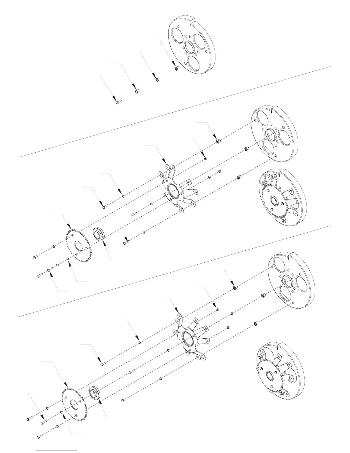
Self Clinching
Nut Installation
780 Installation
No Windlocks
1919
1616
2525
2626
1919
2929
1313
88
1515
2727
1515
790 Installation
With Windlocks
1515
2727
2828
1919
88
2929
1313
88
1515
88
2828
Figure 2a-4:1 Hoist
See Page 9 For
Bill Of Materials
4
 Loading...