

Overhead door 301, 303, 304, 307, 308 Installation Instructions Manual
...
Carriage House Collection
Models: 301, 302, 303,
304, 307, 308, 309
t o r s I o n s p r I n g ( s ) ,
standard lIft
InstallatIon InstructIons
T a b l e O f C o n t e n t s
Parts Breakdown 2
Parts Breakdown 2
Pre-Installation 3
Safety Information 3
Tools Required 4
Package Contents 4
Door Section Identification 4
Removing an Existing Door 5
Preparing the Opening 5
Installation 6
Optional Installation 13
Trolley Arm Hookup 13
Inside Lock 13
Pull Down Rope 13
Maintenance 14
Cleaning Your Garage Door 14
Painting Your Garage Door 14
Operation and Maintenance 14
Warranty 16
Distributor Locator Information 18
IMPORTANT NOTICES!
To avoid possible injury, carefully read and understand instructions
completely before installing and operating the garage door. Pay
close attention to all warnings and notes. After installation is
complete, fasten this manual near garage door for easy reference.
Overhead Door Corporation
2501 South State Highway 121, Suite 200, Lewisville, TX., 75067
349692 NEW 05/29/2012Part No.©COPYRIGHT 2012 OVERHEAD DOOR CORPORATION
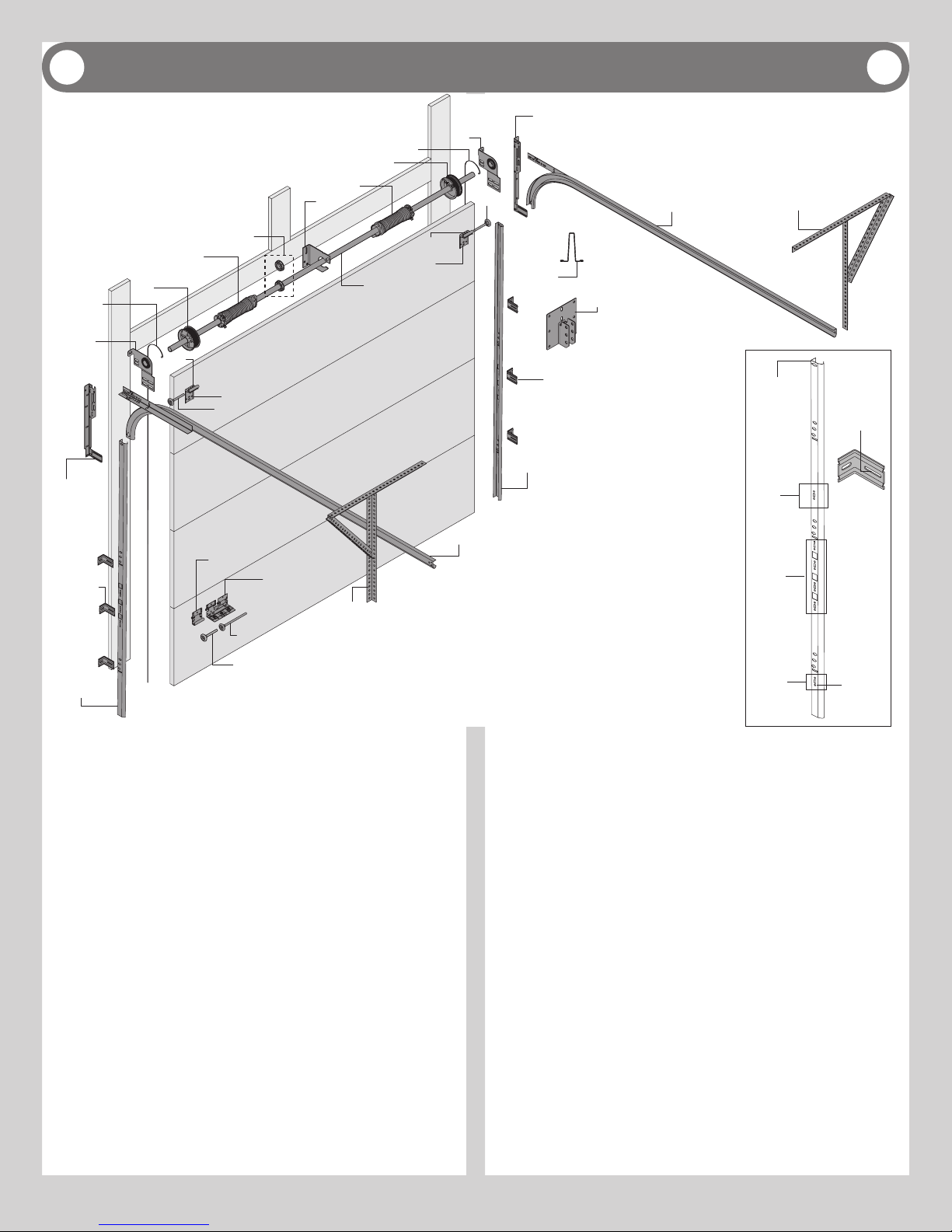
Parts Breakdown
PARTS BREAKDOWN
NOTE: The illustrations shown on this page are general
representations of the door parts. Each specific door
models may have unique variations.
J1.
J8.
J7.
J5.
J9.
J3.
F2.
F1.
C1.
A1.
D1.
B1.
D2.
K1.
J7.
J2.
E1.
E2.
E3.
J6.
J9.
E4.
F1.
F2.
A2.
J4.
C1.
G1.
H1.
B1.
I4.
I1.
I2.
K2.
Top of vertical
track
3rd
hole set
2nd
hole set
B1. (Fully
Adjustable
Feature)
C2.
C1.
I3.
A. FLAG ANGLES (AS REQUIRED):
A1. Fully Adjustable (F.A.) Flag Angles
B. JAMB BRACKETS (AS REQUIRED):
B1. Fully Adjustable (F.A.) Jamb Brackets
C. TRACK ROLLERS:
C1. Short Stem Track Rollers
C2. Long Stem Track Rollers
D. GRADUATED END HINGES:
D1. Single Graduated End Hinges (S.E.H.), Anti-Pinch
D2. Single Graduated End Hinges (S.E.H.), Industry Standard
E. STACKED SECTIONS:
E1. Top Section
E2. Intermediate(s) Section
E3. Lock Section
E4. Bottom Section
F. TOP FIXTURE (AS REQUIRED):
F1. Top Fixture Bases - (L-Shaped)
F2. Top Fixture Slides - (L-Shaped)
G. STRUT(S) (AS REQUIRED):
G1. Strut (U-shaped)
H. DRAWBAR OPERATOR BRACKET (FOR TROLLEY OPERATED DOORS):
H2. Drawbar Operator Bracket
I. TRACKS:
I1. Left Hand Horizontal Track Assembly
I2. Right Hand Horizontal Track Assembly
I3. Left Hand Vertical Track
I4. Right Hand Vertical Track
J. TORSION SPRING ASSEMBLY:
J1. Center Bracket
J2. Torsion Shaft
J3. Left Hand End Bearing Bracket
J4. Right Hand End Bearing Bracket
J5. Left Hand Cable Drum
J6. Right Hand Cable Drum
J7. Right Hand and Left Hand Torsion Springs (As Required)
J8. Center Bracket Bushing
J9. Counterbalance Lift Cables
K. REAR BACK HANGS:
K1. Left Hand Rear Back Hang Assemblies
K2. Right Hand Rear Back Hang Assemblies
1st
hole set
Lower hole
of hole/
slot pattern
2
WARNING
WARNING
WARNING
Pre-Installation
Safety Information
OVERVIEW OF POTENTIAL HAZARDS: READ THIS SAFETY INFORMATION CONVENTIONS
USED IN THESE INSTRUCTIONS:
Garage doors are large, heavy objects that move with the help of springs under high tension
and electric motors. Since moving objects, springs under tension, and electric motors can
cause injuries, your safety and the safety of others depend on you reading the information in
this manual. If you have questions or do not understand the information presented, call your
nearest trained door system technician or visit our website.
The following Safety Alert symbol and signal words are used throughout this manual to call
attention to and identify different levels of hazard and special instructions.
WARNING WARNING
THIS IS THE SAFETY ALERT SYMBOL. THIS SYMBOL ALERTS YOU TO
POTENTIAL HAZARDS THAT CAN KILL OR HURT YOU AND OTHERS. ALL
SAFETY MESSAGES WILL FOLLOW THE SAFETY ALERT SYMBOL AND
THE WORD “DANGER”, “WARNING”, OR “CAUTION”.
DANGER: Indicates an imminently hazardous situation which, if NOT avoided, will result in
death or serious injury.
WARNING: Indicates a potentially hazardous situation which, if NOT avoided, could result in
death or serious injury.
CAUTION: Indicates a potentially hazardous situation which, if NOT avoided, may result in
injury or property damage.
NOTE: Indicates important steps to be followed or important considerations.
IMPORTANT SAFETY INSTRUCTIONS: READ AND FOLLOW ALL INSTRUCTIONS SAVE
THESE INSTRUCTIONS
Potential Hazard Effect Prevention
Keep people clear of opening
while Door is moving.
Do NOT allow children to play
Could result in Death or Serious
Injury
Could result in Death or Serious
Injury
Could result in Death or Serious
Injury
READ THIS SAFETY INFORMATIONS:
Read this installation instruction booklet completely before starting installation of the door. If
you have questions or do not understand the information presented in these instructions, call
your nearest trained door system technician.
While not required for extension spring systems, consider having a trained door system
technician install this door for the optimum installation and performance.
You can install your new garage door yourself, if…
a) You have help (it may weigh up to 500 lbs.),
b) You have the right tools and reasonable mechanical aptitude or experience, and
c) You follow these instructions very carefully.
Garage doors use springs to balance them. There are two types of springs installed — extension or torsion. Each of these is available in either a standard or low ceiling assembly option.
Please look at the drawings to see which spring type your old door has.
with the Door Opener.
Do NOT operate a Door that jams
or one that has a broken spring.
Turn OFF power before removing
opener cover.
When replacing cover, make sure
wires are NOT pinched or near
moving parts.
Opener must be fully grounded.
Do NOT try to remove, install, repair or adjust springs or anything
to which door spring parts are
fastened, such as, wood blocks,
steel brackets, cables or other
like items.
Installations, repairs and adjust-
ments must be done by a trained
door system technician using
proper tools and instructions.
WARNING WARNING
IF YOUR OLD DOOR OR NEW DOOR USES TORSION SPRINGS, DO NOT
ATTEMPT TO REMOVE, INSTALL, REPAIR OR ADJUST THE SPRINGS
YOURSELF. HAVE A TRAINED DOOR SYSTEM TECHNICIAN REMOVE,
INSTALL, REPAIR OR ADJUST THEM. ATTEMPTING TO REMOVE, INSTALL,
REPAIR OR ADJUST A TORSION SPRING ASSEMBLY WITHOUT PROPER
TRAINING OR TOOLS MAY RESULT IN AN UNCONTROLLED RELEASE OF
SPRING FORCES WHICH CAN CAUSE SERIOUS INJURY.
• In removing a garage door that has Extension springs, follow the instructions carefully,
including the use of C-clamps or locking pliers on both sides of the door in order to keep the
door from moving once the springs are removed.
• Low Headroom doors require special instructions. Check headroom requirements located in
Preparing The Opening, before beginning.
• Be sure all hardware components for your new door are included before removing existing
door. If your door is missing any parts, call the company from whom you purchased your unit.
• Allow enough time to do the work; removing an existing door will take approximately 1-3
hours.
• A typical installation takes between 9 and 12 hours to complete.
• Keep in mind when planning the installation that the garage will be open and unsecured
when disassembling the old and assembling the new door.
• If the garage door is the only opening in the structure make sure everything you need is
inside. You will have no way of leaving the garage until the track is assembled and installed.
This will take approximately 5 hours.
• Never reuse old track or hardware. Only the track specified and supplied with the door
should be used.
• To avoid damage to the door, you must reinforce the top section of the door in order to
provide a strengthened mounting point for attachment of an automatic opener.
• Original replacement parts are recommended if repairs are ever required to your door.
• Be sure that your garage complies with all applicable state and or local ventilation requirements before you enclose any vehicles in the garage. Good ventilation avoids fire and health
hazards caused by fumes accumulating within a well-sealed garage.
• Do NOT permit children to play beneath or with any garage door or electric operating
controls.
• Keep hands and fingers clear of section joints, track, and other door parts when the door
is opening and closing to avoid injury. If lift handles are provided, ensure that the lift handles
are located for safe operation as well as easy use.
• Bolts must be installed at the rear end of horizontal tracks. These act to stop the rollers and
keep the door from rolling off the back of the track.
• Track installations must use sway braces on the rear track hangers to prevent sideways
movement. If the tracks are NOT firmly stabilized they might spread, allowing the door to fall
and cause severe injury and damage.
• Springs, cables, and Bottom Corner Brackets are under strong spring tension. Do NOT
attempt to remove, repair or adjust any fasteners on these components or anything to which
these parts are attached, such as wood blocks, steel brackets, or other like items. You could
suddenly release spring forces and risk severe injury.
• If the garage door and/or any of the supporting tracks are damaged, operating the door
could be hazardous. Take the door out of service and call a trained door system technician to
promptly service or repair the door.
• KEEP DOORS PROPERLY BALANCED. An improperly balanced door increases the risk of
severe injury or death. Have a trained door system technician make repairs to cables, spring
assemblies and other hardware as necessary.
• Doors equipped with automatic door operators can cause serious injury or death if NOT
properly adjusted and operated. To ensure safety of these doors:
a) Never let children operate or play with the door controls. Keep the remote control away
from children,
b) Always keep the moving door in sight and people and objects away from the door until the
door is completely closed. NO ONE SHOULD CROSS THE PATH OF THE MOVING DOOR,
c) NEVER GO UNDER A STOPPED, PARTIALLY OPEN DOOR,
d) Test operator monthly. The door MUST reverse on contact with a 1-1/2” high object (or a
2” x 4” board laid flat) at the center of the doorway on the floor. If the door does NOT reverse,
re-test the door operator after adjusting either the force or the limit of travel in accordance
with the manufacturer’s instructions. Failure to adjust the operator properly may result in
severe injury or death,
e) When possible, use the emergency release only when the door is closed. Use caution when
using this release with the door open. Weak or broken springs are capable of increasing the
rate and force of door closure and increasing the risk of severe injury or death, and
f) If your door has a pull down rope or locking mechanism, you must remove the rope and
either disable or remove any door locks.
Please Do Not Return This Product To The Store. Contact your local Overhead Door Ribbon Distributor. To find your local Overhead Door Ribbon
Distributor, refer to your local yellow pages business listings or go to the Find a Ribbon Distributor section online at www.OverheadDoor.com.
3
WARNING WARNING
PRIOR TO WINDING OR MAKING ADJUSTMENTS TO THE SPRINGS, ENSURE YOU’RE WINDING IN THE PROPER DIRECTION AS STATED IN THE
INSTALLATION INSTRUCTIONS. OTHERWISE, THE SPRING FITTINGS MAY
RELEASE FROM SPRING IF NOT WOUND IN THE PROPER DIRECTION AND
COULD RESULT IN SEVERE OR FATAL INJURY.
IMPORTANT: RIGHT AND LEFT HAND IS ALWAYS DETERMINED FROM INSIDE THE BUILDING
LOOKING OUT.
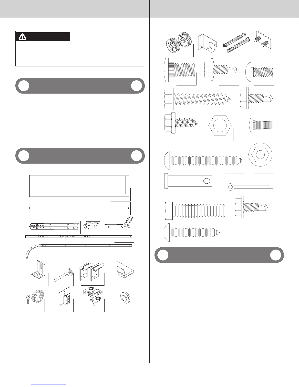
Tools Required
Cable drums RH/LH Torsion springs RH/LH
(2) 3/8”-16 x 3/4”
Truss head bolts
Center bracket
1/4”-20 x 7/8” Self
drilling screws (as required)
Stud Plate
(as required)
(4) 1/4”-20 x 5/8”
Carriage bolts
• Power drill
• Drill bits: 1/8”,
3/16”, 9/32”, 7/16”,
1/2”
• Ratchet wrench
• Socket driver: 7/16”
• Sockets: 7/16”,
1/2”, 9/16”, 5/8”
• Phillips head
screwdriver
• Locking Pliers
• (2) Vice clamps
• Wrenches: 3/8”,
7/16”, 1/2”, 9/16”,
5/8”
• 1/4” Torx bit
• Hammer
• Tape measure
• Step Ladder
• Level
• Pencil
• Leather gloves
• Safety glasses
• Approved winding
rods
Package Contents
NOTE: Depending on the door model, some parts listed will not be supplied if not required.
Rear Back Hangs may not be included with your door.
Door sections (as required)
Torsion shaft
(2) Horizontal track angles (as required)
F.A. flag angles RH/LH (as required)
Vertical tracks RH/LH
Horizontal tracks RH/LH
5/16” x 1 5/8” Hex head lag screws
1/4”-14 x 5/8” Self tapping
screws (as required)
5/16” x 1-1/4”
(2) 3/8”-16 x 1-1/2” Hex bolts
5/16” x 1-5/8” Tamper-resistant
hex head lag screws (as required)
5/16” x 2” Tamper-resistant hex head
Clevis pin
(as required)
(2) 3/8”- 16 Hex nuts
lag screw (as required)
Door Section Identification
1/4”-20 x 5/8” Self
drilling screws (as required)
1/4”-20 x 9/16”
Track bolts (as required)
1/4”- 20 Flanged
hex nuts (as required)
Cotter pin
1/4”-20 x 11/16” Self
drilling screws (as required)
F.A. jamb brackets
(as required)
Pull down rope
(if included)
Track rollers
Drawbar operator
bracket (if included)
Please Do Not Return This Product To The Store. Contact your local Overhead Door Ribbon Distributor. To find your local Overhead Door Ribbon
Distributor, refer to your local yellow pages business listings or go to the Find a Ribbon Distributor section online at www.OverheadDoor.com.
(2) Top fixtures
(2) End bearing
brackets
Weather seals & nails
(If included)
Center bracket
bushing
Graduated end and center hinges are always pre-attached at the top of each section (except
top section) and the graduated end hinges are stamped for identification, #1, #2, #3, and #4
(#4 only on five section doors). The stamp identifies the stacking sequence of the section.
The sequence is always determined by #1 being the bottom section to #3 or #4 being the
highest intermediate section. If the stamp on the graduated end hinge is illegible, refer to
the section side view illustration. The section side view illustration shows the graduated end
hinge profile of all sections, and can also be used to identify each section.
The BOTTOM SECTION can be identified by #1 graduated end hinges, the factory attached
bottom astragal and by the factory attached bottom corner brackets.
The LOCK SECTION can be identified by #2 graduated end hinges on a 4 section high door
and by #3 graduated end hinges on a 3 section high door.
The INTERMEDIATE SECTION can be identified by #3 graduated end hinges (Only on a 4
section high door).
NOTE: #4 graduated end hinges are used on the fourth section of five section doors.
The TOP SECTION can be identified with no pre-installed graduated end or center hinges.
4

operated, 2-1/2” (64 mm) of additional headroom is required.
Backroom requirement: Backroom is defined as the distance needed from the opening
back into the garage to allow the door to open fully.
Top section
#3
Intermediate section
#2
Lock section
#1
1-3/8”
#3 Graduated
end hinge
1-1/8”
#2 Graduated
end hinge
7/8”
#1 Graduated
end hinge
BACKROOM REQUIREMENTS
DOOR HEIGHT TRACK MANUAL LIFT MOTOR OPERATED
6’0” - 7’0” 15” Radius 98” (2489 mm) 125” (3175 mm)
7’1” - 8’0” 15” Radius 110” (2794 mm) 137” (3480 mm)
HEADROOM REQUIREMENTS
TRACK TYPE SPACE NEEDED
15” Radius Track 14 1/2” (368 mm)
Min. Side
Suitable mounting surface
2”x 6” lumber minimum
Header board 2”x 6”
lumber preferred
Headroom
room
Clearance
is 3 1/2”
Backroom
Bottom weather
seal
Typical graduated
end hinge
stamping location
Bottom section
Bottom corner
bracket
Bottom weather seal
Section side view illustration
Removing an Existing Door
IMPORTANT: COUNTERBALANCE SPRING TENSION MUST ALWAYS BE RELEASED BEFORE
ANY ATTEMPT IS MADE TO START REMOVING AN EXISTING DOOR.
WARNING WARNING
A POWERFUL SPRING RELEASING ITS ENERGY SUDDENLY CAN CAUSE
SEVERE OR FATAL INJURY. TO AVOID INJURY, HAVE A TRAINED DOOR
SYSTEM TECHNICIAN, USING PROPER TOOLS AND INSTRUCTIONS,
RELEASE THE SPRING TENSION.
Preparing the Opening
IMPORTANT: IF YOU JUST REMOVED YOUR EXISTING DOOR OR YOU ARE INSTALLING A
NEW DOOR, COMPLETE ALL STEPS IN PREPARING THE OPENING.
To ensure secure mounting of track brackets, side and center brackets, or steel angles to
new or retro-fit construction, it is recommended to follow the procedures outlined in DASMA
technical data sheets #156, #161 and #164 at www.dasma.com.
The inside perimeter of your garage door opening should be framed with wood jamb
and header material. The jambs and header must be securely fastened to sound framing
members. It is recommended that 2” x 6” lumber be used. The jambs must be plumb and the
header level. For low headroom applications, the jambs should extend to the ceiling height.
Minimum side clearance required, from the opening to the wall, is 3-1/2” (89 mm).
IMPORTANT: CLOSELY INSPECT JAMBS, HEADER AND MOUNTING SURFACE. ANY WOOD
FOUND NOT TO BE SOUND, MUST BE REPLACED.
For Torsion counterbalance systems, a suitable mounting surface (2” x 6”) must be firmly
attached to the wall, above the header at the center of the opening.
NOTE: Drill a 3/16” pilot hole in the mounting surface to avoid splitting the lumber. Do not
attach the mounting surface with nails.
Weather seal (may not be included):
Cut or trim the weather seal (if necessary) to the header and jambs.
NOTE: If nailing product at 40°F or below, pre-drilling is required.
Align the header seal 1/8” to 1/4” inside the header, and temporarily secure it to the header
with equally spaced nails. Next, fit the jamb seals up tight against the header seal and 1/8”
to 1/4” inside the jamb. Temporarily secure the jamb seals with equally spaced nails. This
will keep the bottom section from falling out of the opening during installation. Equally space
nails approximately 12” to 18” apart.
NOTE: Do not permanently attach weather seal to the jamb at this time.
Headroom requirement: Headroom is defined as the space needed above the top of the
door for tracks, springs, etc. to allow the door to open properly. If the door is to be motor
Min. Side
room
Clearance
is 3 1/2”
Weather seal
Plumb
jambs
Finished
Jambs
Level header
Finished
Height
Door width
Door
Jamb
Jamb
Nail
1/8” to 1/4”
1/8” to 1/4”
Weather
Seal
Weather
Seal
Door Section
Please Do Not Return This Product To The Store. Contact your local Overhead Door Ribbon Distributor. To find your local Overhead Door Ribbon
Distributor, refer to your local yellow pages business listings or go to the Find a Ribbon Distributor section online at www.OverheadDoor.com.
5
INSTALLATION
Before installing your door, be certain that you have read and followed all of the instructions covered in the pre-installation section of this manual. Failure to do so may result in an
improperly installed door.
NOTE: Reference TDS 160 for general garage door terminology at www.dasma.com.
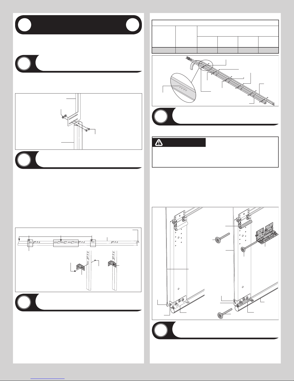
Attaching Flag Angles to Vertical Tracks
1
NOTE: Flag angles are right and left handed.
Hand tighten the left hand flag angle to the left hand vertical track using (2) 1/4”-20 x
9/16” track bolts and (2) 1/4”-20 flange hex nuts. Repeat for other side. Flange nuts will be
secured after flag angle spacing is completed in step, Top Section.
2
NOTE: The bottom jamb bracket is always the shortest bracket, while the center jamb
bracket is the next tallest. If three jamb brackets per side are included with your door, you will
have received a top jamb bracket, which is the tallest.
To attach the bottom jamb bracket, locate lower hole of the hole/ slot pattern of the 1st hole
set on the vertical track. Align the slot in the jamb bracket with the lower hole of the hole/ slot
pattern. Secure jamb bracket using (1) 1/4”-20 x 9/16” track bolt and (1) 1/4”-20 flange hex
nut. Repeat for other side.
Place the center jamb bracket over the lower hole of the hole/ slot pattern that is centered
between the bottom jamb bracket and flag angle of the 2nd hole set. Secure jamb bracket
using (1) 1/4”-20 x 9/16” track bolt and (1) 1/4”-20 flange hex nut. Repeat for other side.
If a top jamb bracket was included, secure it to vertical track using the lower hole of the hole/
slot pattern in the 3rd hole set and (1) 1/4”-20 x 9/16” track bolt and (1) 1/4”-20 flange hex
nut. Repeat for other side.
1st hole set
(10”)
Lower hole of
hole/ slot pattern
Tools: None
Flag angle
1/4”-20
Flange hex nuts
Vertical
track
1/4”- 20 x 9/16”
Track bolts
Attaching F.A. Jamb Brackets
Tools: None
2nd hole set
(34”)
1/4”- 20
Flange hex nut
Jamb
bracket
3rd hole set
(58”)
1/4”- 20 x
9/16”
Track bolt
Vertical track
Top of track
Jamb bracket
in place
Repeat same process for the right hand side. Set tracks aside.
Horizontal Track Angle Schedule
Door Height
7’0” - 8’0” 3 Or 4 X - - -
Fixed
position
offset holes
How Many
Sections High
Slots
12 34
Fixed Position Offset Holes
1 2 3 4
Hole
1/4”- 20 x 9/16”
Track bolts
Slots
1/4”- 20
Flange hex nuts
Left hand horizontal track angle
Left hand
horizontal
track
Cable Drum Assemblies and Track Rollers
4
NOTE: The bottom section can be identified by the smallest graduated edge hinge of the
factory installed graduated edge hinges, see Parts Breakdown on page 2.
Tools: None
WARNING WARNING
FAILURE TO ENSURE TIGHT FIT OF CABLE LOOP OVER MILFORD PIN
COULD RESULT IN COUNTERBALANCE LIFT CABLE COMING OFF THE PIN,
ALLOWING THE DOOR TO FALL, POSSIBLY RESULTING IN SEVERE OR
FATAL INJURY.
Uncoil the counterbalance lift cables. Starting on the left hand side, place the cable loop on
the milford pin of the bottom corner bracket. Insert a short stem track roller into the factory
attached bottom corner bracket and another into the #1 graduated end hinge at the top of
the bottom section. Repeat for other side.
NOTE: Check to ensure cable loops fits tightly over the milford pins.
NOTE: Larger doors will use long stem track rollers with double graduated end hinges.
NOTE: Verify bottom weather seal is aligned with bottom section. If there is more than 1/2”
excess weather seal on either side, trim weather seal even with bottom section.
#1 Single
graduated
end hinge
(Hinge tube)
Short stem
track roller
Long
stem
track
roller
Double graduated
end hinge
(Hinge tube)
Bottom
section
Bottom
section
Counterbalance
Counterbalance
lift cable
lift cable
Horizontal Track Angles
3
NOTE: For larger doors, a full length horizontal track angle may not already be spot welded to
the horizontal track. If the horizontal track angle is not welded, the horizontal track angle will
be installed, as shown.
Position the left hand horizontal track angle up against the left hand horizontal track, as
shown.
Referring to the horizontal track angle schedule, align one of the fixed position offset holes
(1, 2, 3, 4) in the horizontal track angle with the hole in the horizontal track. Fasten using (1)
1/4”-20 x 9/16” track bolt and (1) 1/4”-20 flange hex nut. Align the rest of the slots in the
horizontal track angle with the slots in the horizontal track. Secure the horizontal track angle
to the horizontal track using 1/4”-20 x 9/16” track bolts and 1/4”-20 flange hex nuts, as
shown.
Tools: Hammer, 9/16” Wrench
Please Do Not Return This Product To The Store. Contact your local Overhead Door Ribbon Distributor. To find your local Overhead Door Ribbon
Distributor, refer to your local yellow pages business listings or go to the Find a Ribbon Distributor section online at www.OverheadDoor.com.
Cable
loop
Milford
pin
Bottom
corner
bracket
Cable loop
Milford
pin
Short stem
track roller
Bottom
corner
bracket
Bottom Section
5
Center the bottom section in the door opening. Level the section using wooden shims (if
necessary) under the bottom section.
6
Tools: Level, Wooden shims (if necessary)
Bottom
weather
seal
 Loading...