

Page 1
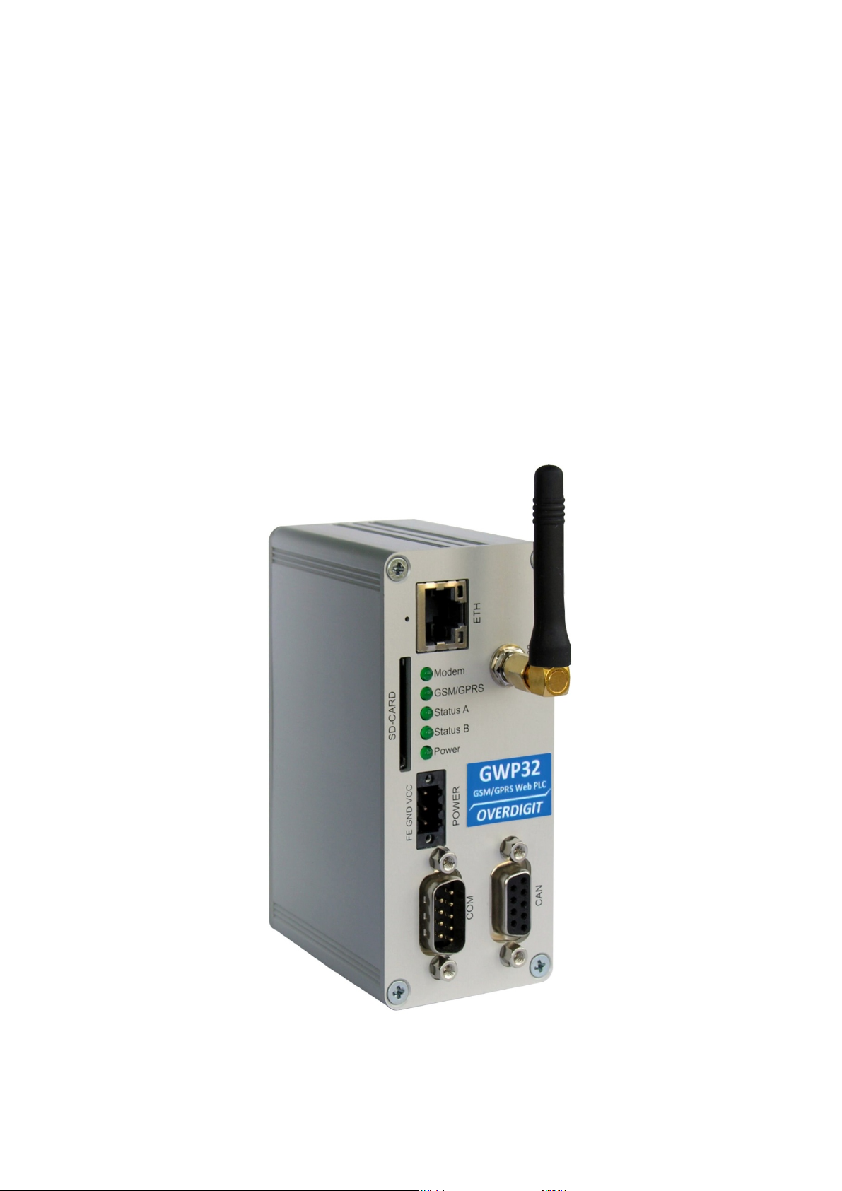
User manual
GSM/GPRS gateway
GWP32 series IPC-line
update: 22-03-2012
IPC-line by OVERDIGIT overdigit.com
Page 2
GWP32 user manual
1. Installing the SIM card and mechanical fixing
The GWP32 modem requires, for GSM/GPRS connection, the installation of a SIM card.
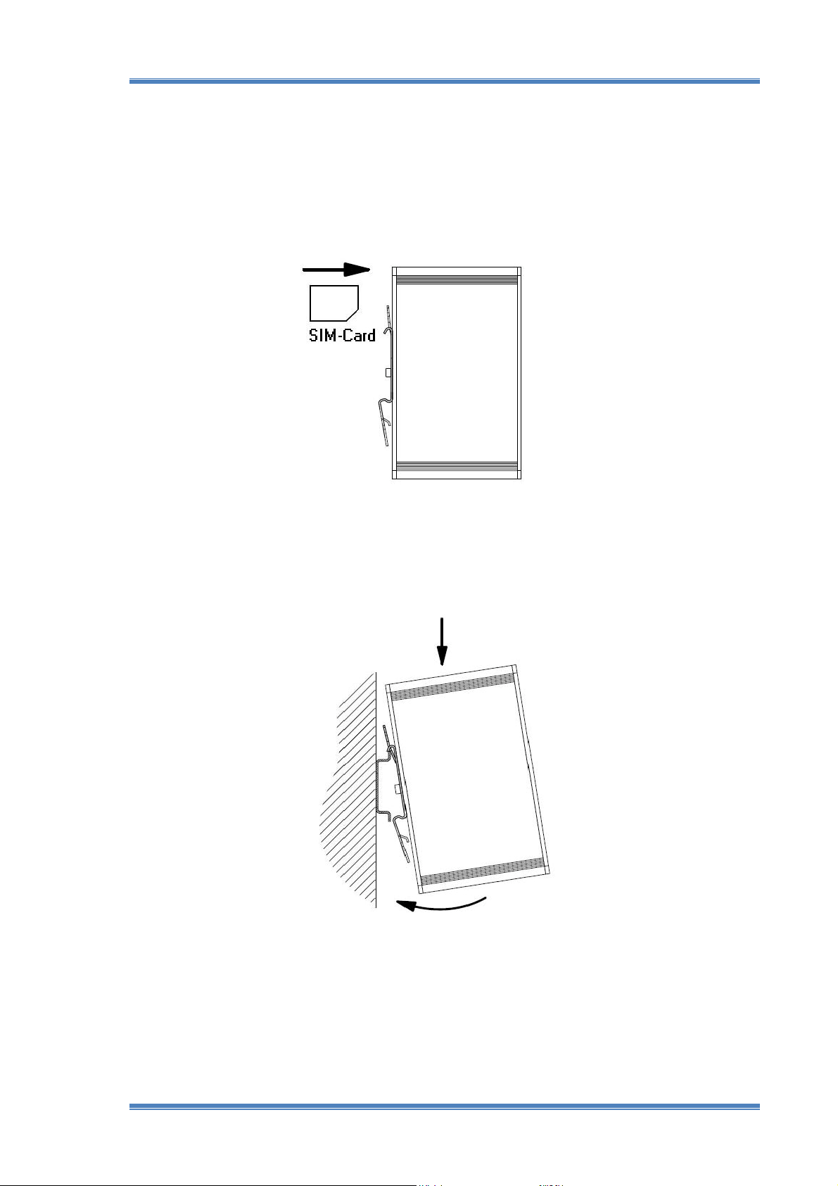
The SIM card must be inserted into the slot on back of the unit before fixing it mechanically on the
DIN rail. Insert the SIM card until it is retained by the spring of the locking system, paying attention
to the correct direction indicated in the figure below:
To remove the SIM card, press it further, to disable the locking system with the subsequent
expulsion.
After installing the SIM card you can fix the GWP32 gateway on DIN rail using the clip provided on
the back as indicated by the following illustration:
NOTE: The GWP32 gateway must be installed taking care to keep, as much as possible, the antenna
away from metal objects or other apparatus. Are available antennas of different types, also
equipped with a magnetic support and connection cable, which can be installed in different and
unshielded positions.
IPC-line by OVERDIGIT Page 2
Page 3
2. Electrical connections
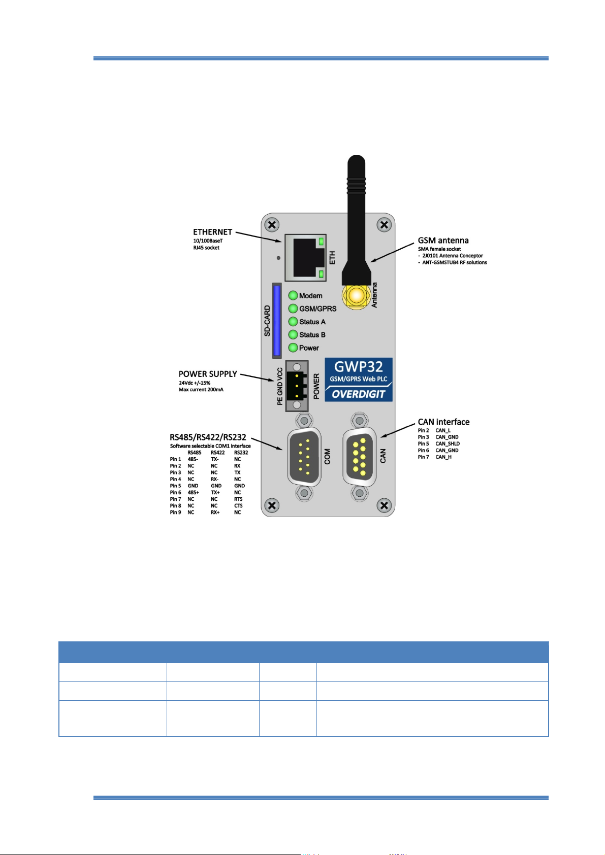
All the electrical connections of GWP32 are accessible on the front panel. The picture below shows
the possible connections and the pin-out of connectors:
GWP32 user manual
NOTE: The RS485 signal lines are indicated with 485+ and 485- where the polarity refers to the
active state of line driving (transmission of bit 0). In other systems the signals are indicated by the
letters A and B, and normally A=485- / B=485+ is the corresponding connection.
To use the COM1 serial port the following parameters must be configured in the file CHIP.INI:
Item Value Default Description
[PLC_CFG]
COM1_HW
COM1
Section of PLC configuration parameters
RS485 / RS422 / RS232 RS485 Select type of hardware driver for the port
USER / PROG USER Select the software use of the port
USER: available for the IEC application through the libraries
PROG: used for the CoDeSys on-line connection
IPC-line by OVERDIGIT Page 3
Page 4
GWP32 user manual
3. Points of intervention and signalling
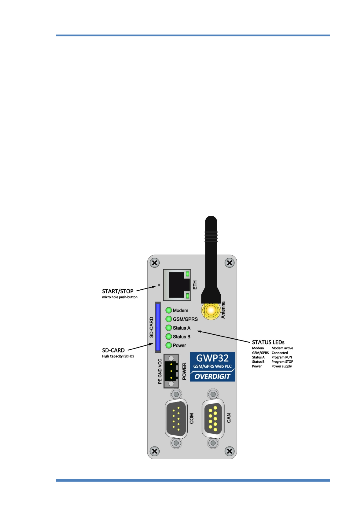
The GWP32 gateway has a slot on the front panel to install an SD card memory used as hard-disk
additional to the internal drive. Is usable both a normal SD card, the first generation, that the
newer SDHC high capacity that can store many gigabytes of data. To use the SD card the driver
program EXTSD.EXE must be inserted into the autoexec.bat file, specifying as a parameter the
name of the disk to be installed (for example B). Normally the device is provided with the driver
already installed for the disk B.
To handle the START/STOP of IEC program, the GWP32 has a button on the front panel which can
be accessed through a thin object with a diameter not exceeding 1 mm. At each press of the button
the RUN/STOP state of the program is inverted. This function can also be used to block the
execution of a IEC program that is wrong. In this case the unit must be powered-on with the button
pressed until the STOP status is reached.
On the GWP32 front panel are also 5 LEDs that indicate the current status of the GSM/GPRS
modem, the RUN/STOP of the IEC program and the proper power supply of the device.
IPC-line by OVERDIGIT Page 4
Page 5

GWP32 user manual
4. Configuration of the GSM/GPRS modem
In the GWP32 gateway is installed a GSM/GPRS modem of GM01 type realized with the G24-L
module of Motorola.
The GM01 modem can realize a permanent connection to the Internet using PPP (Point to Point
Protocol) over GPRS. This can happen in two alternative ways:
1. Installing the GPRS_PPP.EXE driver into autoexec.bat file
2. Using function blocks of MODEM_Lib.lib into the IEC program
In case 1, the GPRS_PPP.EXE connection program should be included in the autoexec.bat file and
the operating parameters should be set into CHIP.INI configuration file.
In this way, after the booting process on power-on, it will run the GPRS_PPP.EXE program that
requires a certain time (about 30 ") to establish a permanent connection to the Internet.
To allow other programs, for example the IEC application, to know the connection status, an item
of configuration file, named PPP_STATUS, is available.
Furthermore, by setting to 1 the value of BATCHMODE item in the [BATCH] section, you can
postpone the next scheduled program (CoDeSys Run Time System) at the connection established.
The BATCHMODE parameter makes it possible to activate the sequential execution of programs
listed into autoexec.bat, as an alternative to their simultaneous execution. The GPRS_PPP.EXE
driver, when the connection is established, however restores the simultaneous execution of
subsequent programs of the autoexec.bat file, allowing the execution of the CoDeSys Run Time
System.
In case 2, the connection functions are handled by the IEC application using the function blocks of
CoDeSys library for the GM01 modem. The integrated management of modem into the IEC
application allows for greater flexibility and control of the connection functions. Moreover, only in
this case, you can use the modem for other functions such as sending and receiving SMS messages.
To simplify the parameterization of GM01 modem function blocks you can still use the values set in
the CHIP.INI configuration file. These settings are considered as default values for the input
variables of the library function blocks. Furthermore, in the absence of the value of a CHIP.INI item,
is still used a fixed value by default.
The following table summarizes the parameters of the CHIP.INI configuration file regarding
specifically the functions of the GM01 modem:
IPC-line by OVERDIGIT Page 5
Page 6

GWP32 user manual
Item Value Default Description
[GM01]
ENABLE
PORT
IGNPIO
DCDPIO
RESTPIO
SIMPIN
PPPAUTH
PPPUSER
PPPPASSWORD
PPPGPRSCONNECT
PPPDIAL
PPPIDLETIMEOUT
PPPSETNEWGATEWAY
PPP_STATUS
RETRY_SECONDS
MODEMTRACE
[DNS]
DYNDNS_ENABLE
DYNDNS_URL
DYNDNS_USER
DYNDNS_PASSWORD
DYNDNS_HOSTNAME
DYNDNS_LAST_IP
[BATCH]
BATCHMODE
Section of GM01 modem parameters
0/1 0 Global enable of GPRS_PPP.EXE driver (0 for not executing the program)
2 2 Serial port used by the modem (no change)
0 0 Pin used for the ignition of the modem (no change)
1 1 Pin used for the modem DCD signal (no change)
17 17 Pin used for the modem RESET (no change)
number blank=disabled Pin number of SIM card (refer to the operator)
0÷4 0 Type of authorization for the PPP connection (refer to the operator)
string blank Username for the PPP connection (refer to the operator)
string blank Password for the PPP connection (refer to the operator)
string AT+CGDCONT=1,
"IP","ibox.tim.it"
string ATD*99***1# Dial string for the PPP connection (refer to the operator)
0÷Sec 0 Timeout in seconds to close the PPP connection in Idle
0/1 1 Set the remote peer as a new gateway
string - Current status of the connection for GPRS_PPP.EXE driver program
0÷Sec 30 Waiting time in seconds to reconnect after the loss of the Link
0/1 0 Enable debug messages on the Telnet window
Section of DynDNS client parameters
0/1 0 Enable DynDNS client for GPRS_PPP.EXE driver program
URL string members.dyndns.
org/nic/update
string name_user Username to access the DynDNS server, choice to create your account
string name_password Password to access the DynDNS server, choice to create your account
URL string name.dyndns.org Host name registered for access the device (example: gwp32.dyndns.org)
IP string - Last IP address registered into DynDNS server
Section of autoexec.bat execution
0/1 0 Simultaneous (0) / sequential (1) execution of programs
Normally left blank (disabled)
0=No, 1=PAP, 2=CHAP, 3=PAPPEER, 4=CHAPPEER
Normally not used (PPPAUTH=0)
Normally left blank (PPPAUTH=0). Used with PPPAUTH > 0
Normally left blank (PPPAUTH=0). Used with PPPAUTH > 0
String with APN for the PPP-GPRS connection (refer to the operator)
Example: AT+CGDCONT=1,"IP","ibox.tim.it"
Example: ATD*99***1#
Normally 0 (timeout disabled)
Normally 1 (enabled)
Values: DISABLED / INIT / INIT_ERR / LINK /
URL where the service of the DynDNS server is available
For “dyndns.com” is: members.dyndns.org/nic/update
In the default: “name” is the [DEVICE]NAME parameter value in CHIP.INI
In the default: “name” is the [DEVICE]NAME parameter value in CHIP.INI
In the default: “name” is the [DEVICE]NAME parameter value in CHIP.INI
Permanently stored for not abuse the service
RETRY
IPC-line by OVERDIGIT Page 6
 Loading...