

Page 1

OPERATING AND
SAFETY MANUAL
MODEL 10 AND MODEL 10 HS
PORTABLE AND STATIONARY
CAR CRUSHER
Study this manual before operating the crusher
Huron, South Dakota
(605) 352-6469
Page 2

TABLE OF CONTENTS
Start-Up Diesel Engine…………………………………………………… 4
Standard Speed Cylinder Operation………..……...……………………. 6
High Speed Cylinder Operation...………….…………………….……… 7
Adjusting Relief Valves…………………….……………………..……… 8
Valve Spool Assembly……..………………………..…………….………. 17
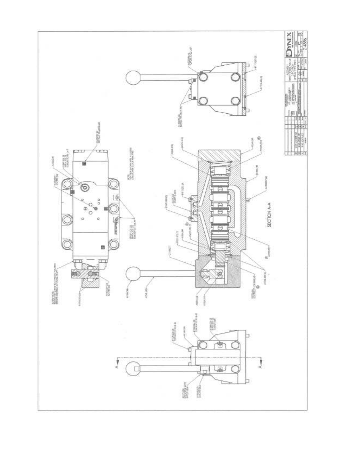
Valve & Pressure Switch Wiring Diagram.……………..……..………. 18
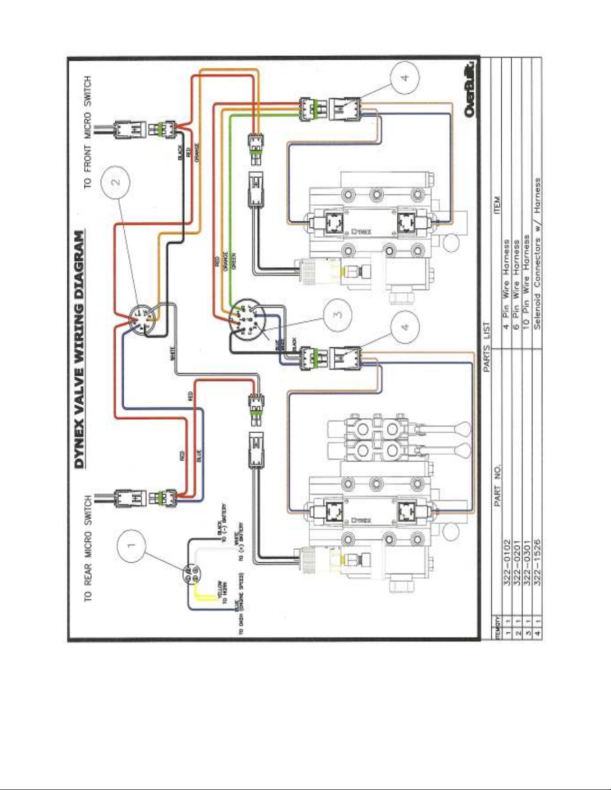
Rod End Final Assembly…………………....…………...……….………. 20
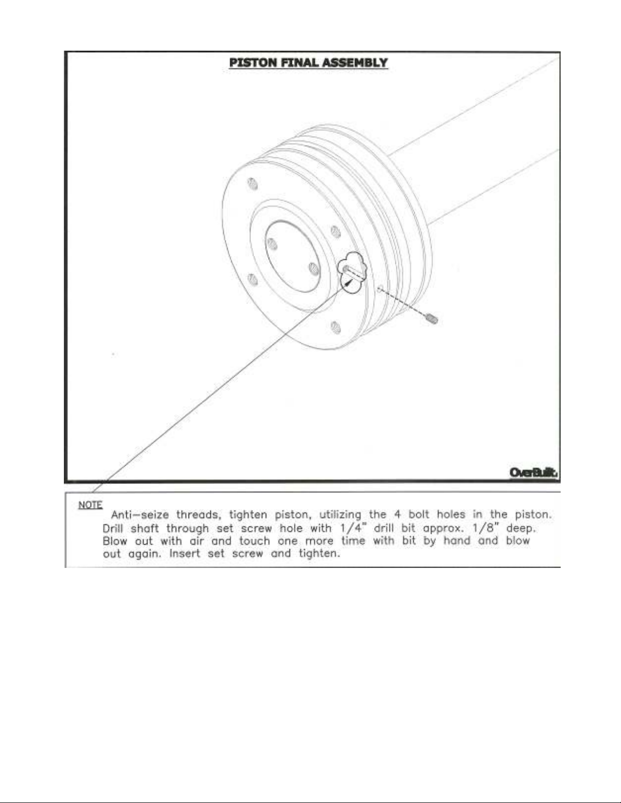
Piston End Final Assembly………………....………………..…..………..21
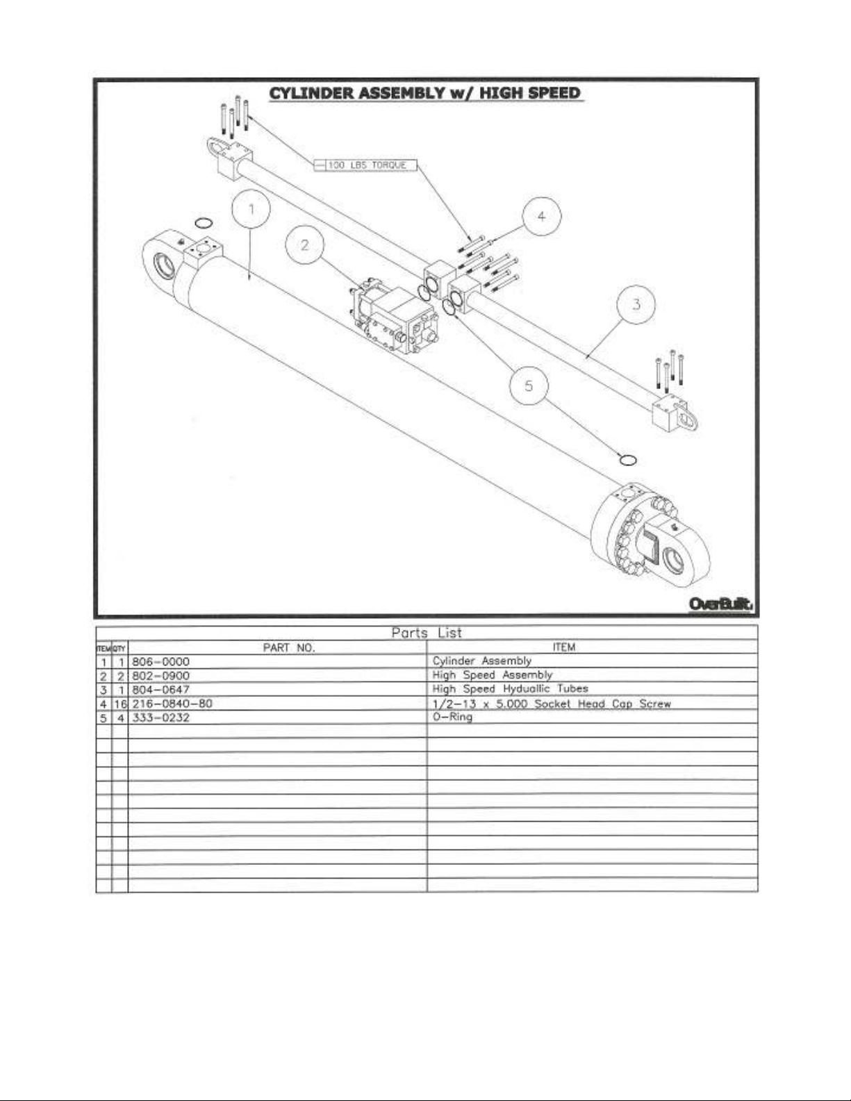
Cylinder Assembly High Speed.…………....……………..……..………. 23
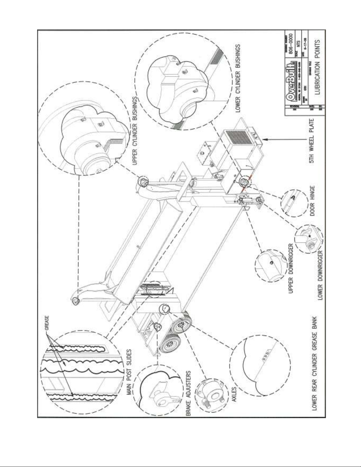
Crusher Lubrication Points……..…..…………………..…….…………. 27
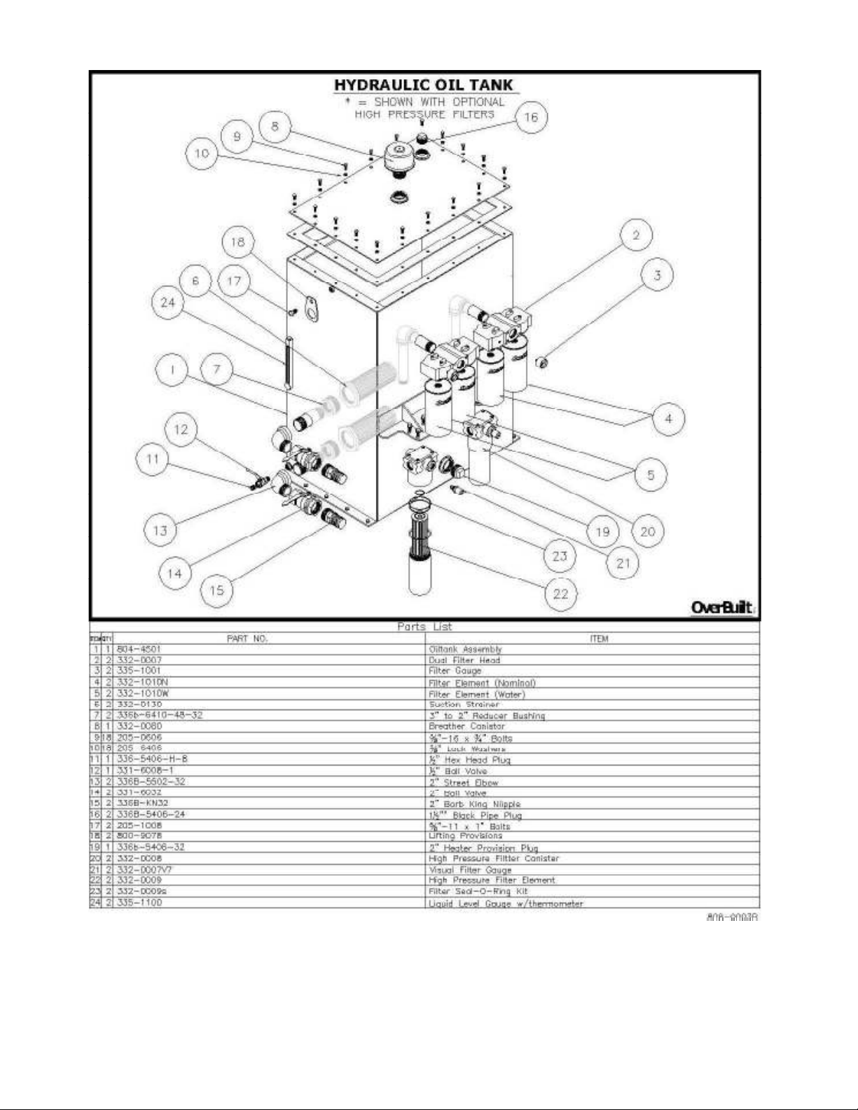
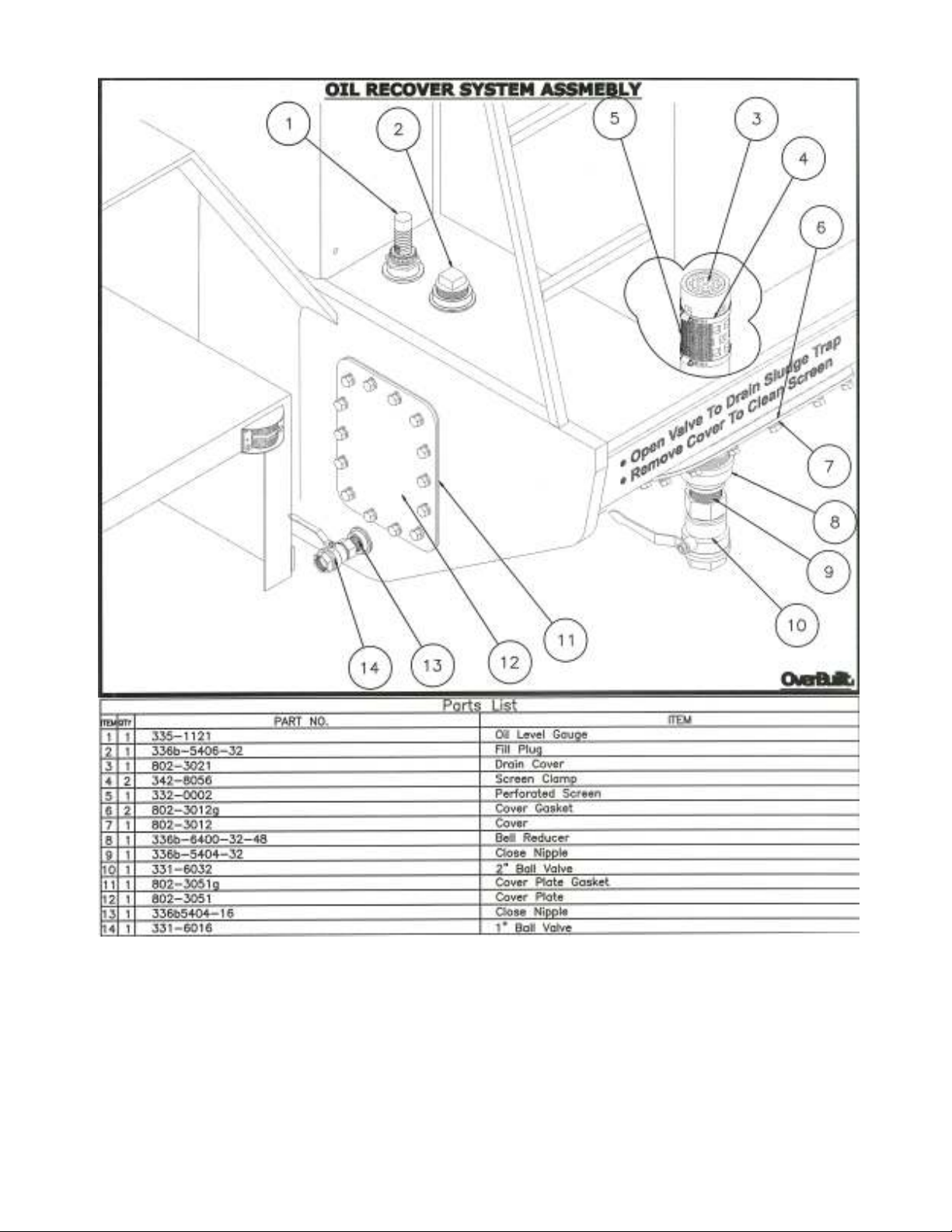
Hydraulic Oil Tank……..…..………………………………….…………. 28
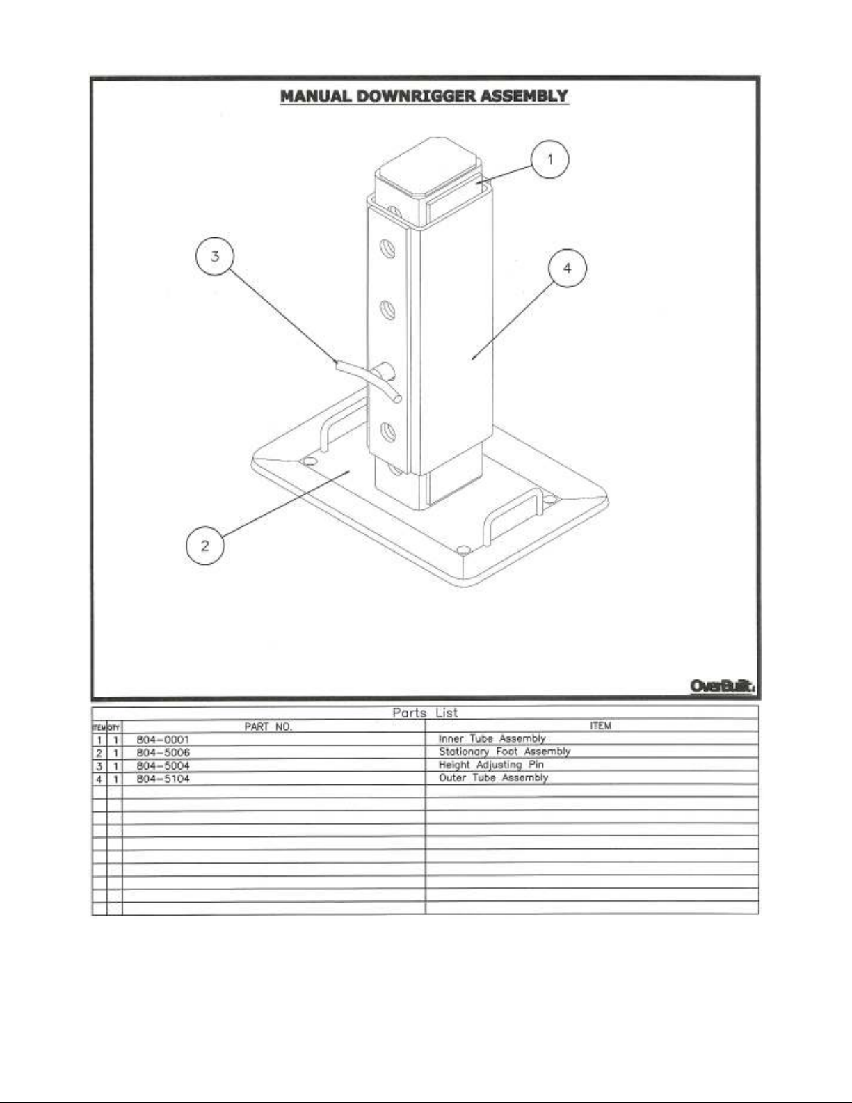
Manual Downrigger Assembly………………………………...………… 29
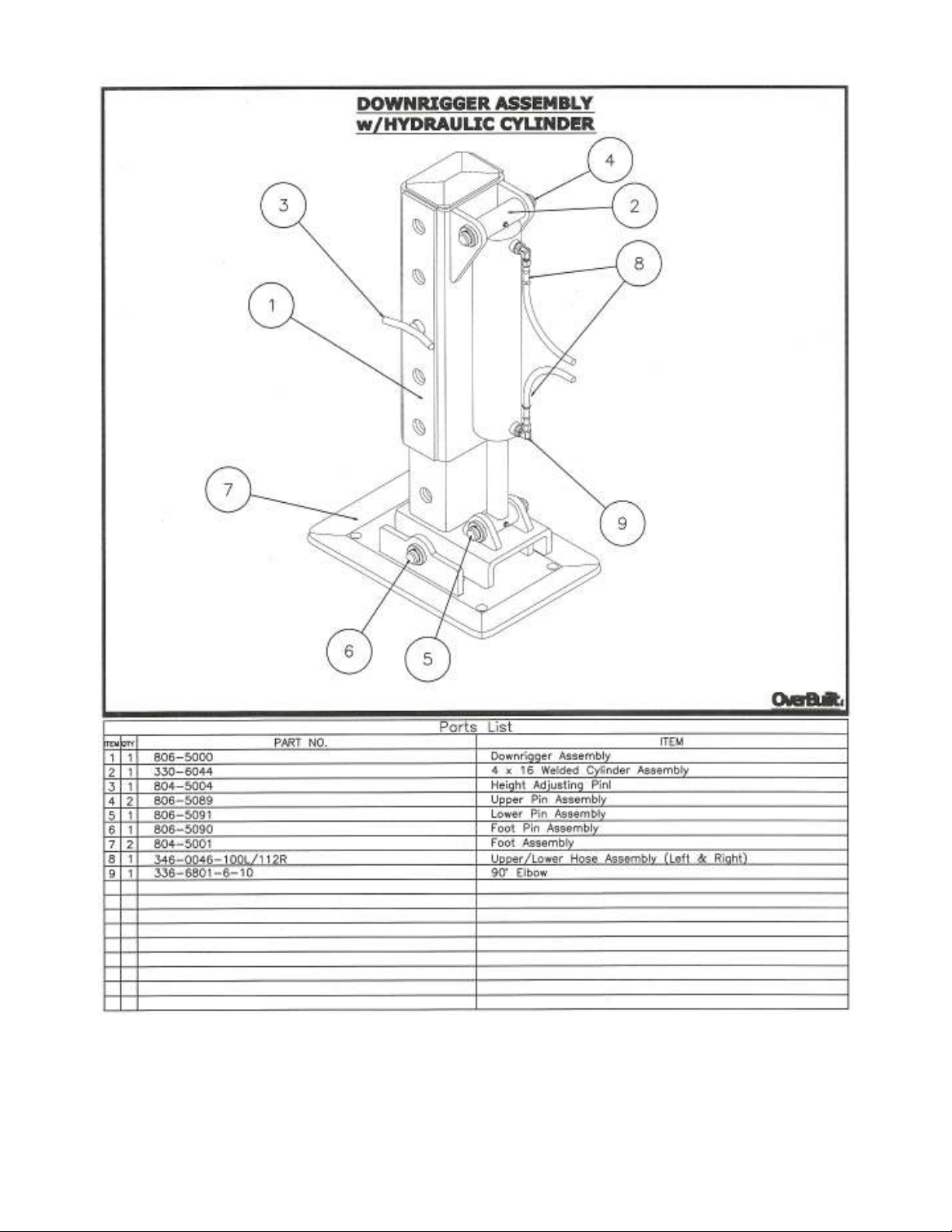
Hydraulic Downrigger Assembly……………………………...………… 30
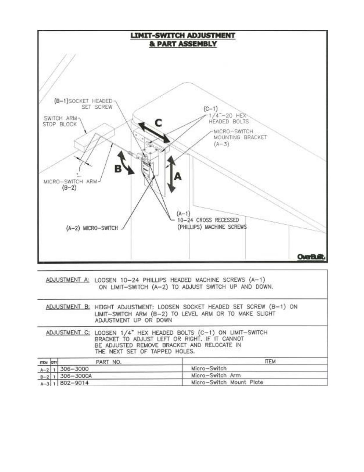
Limit Switch Assembly……………………………………..….…………. 32
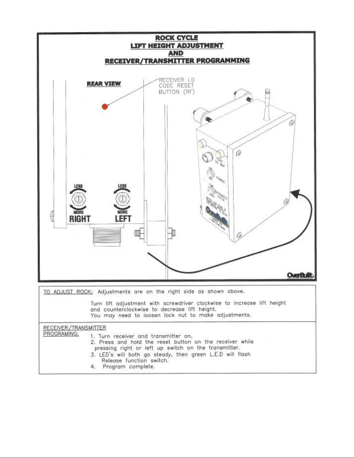
Rock Cycle Lift Height Adjustment……………………...……………… 33
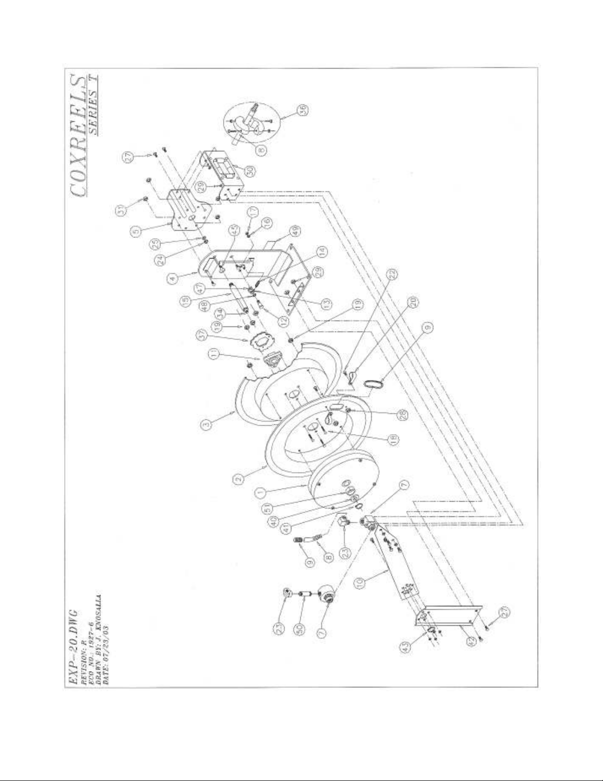
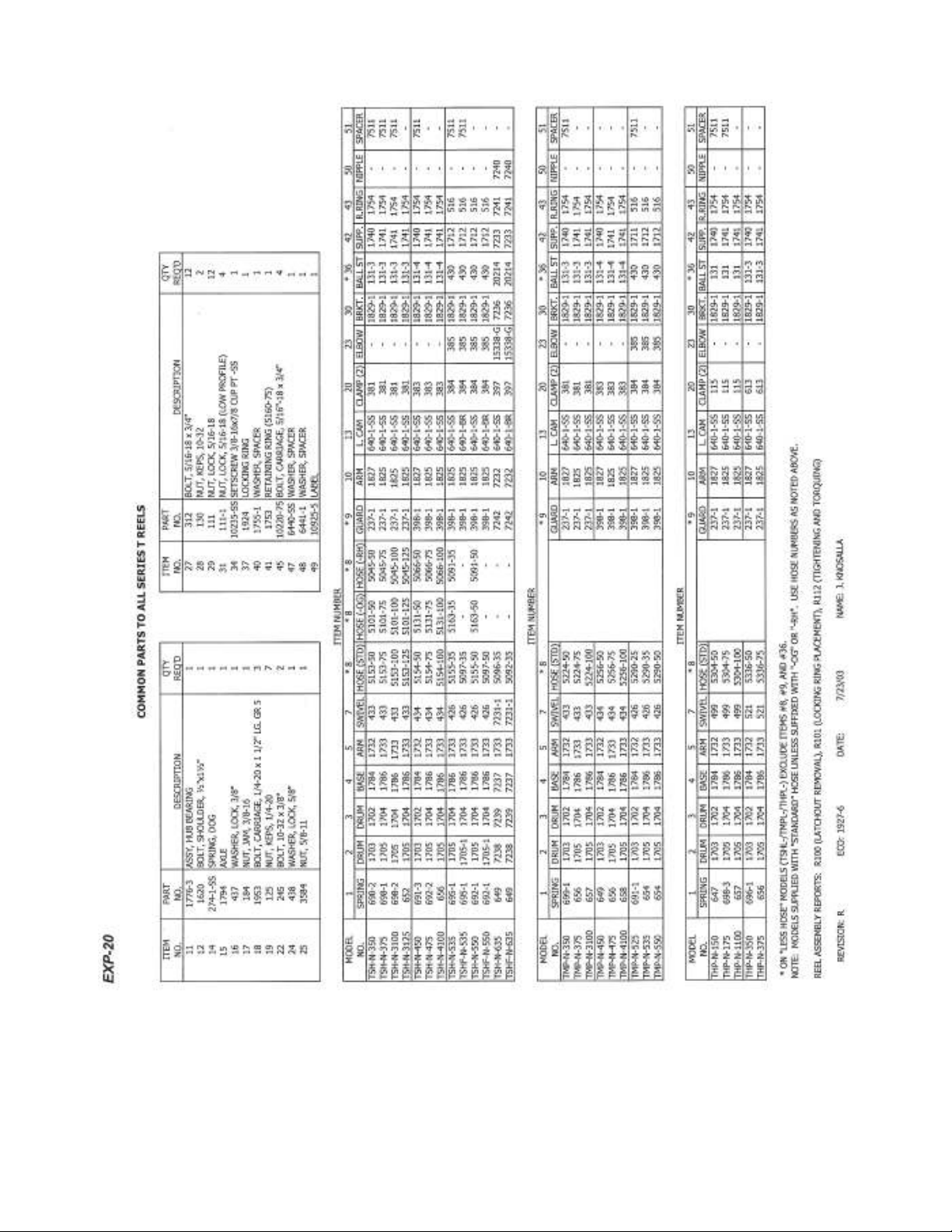
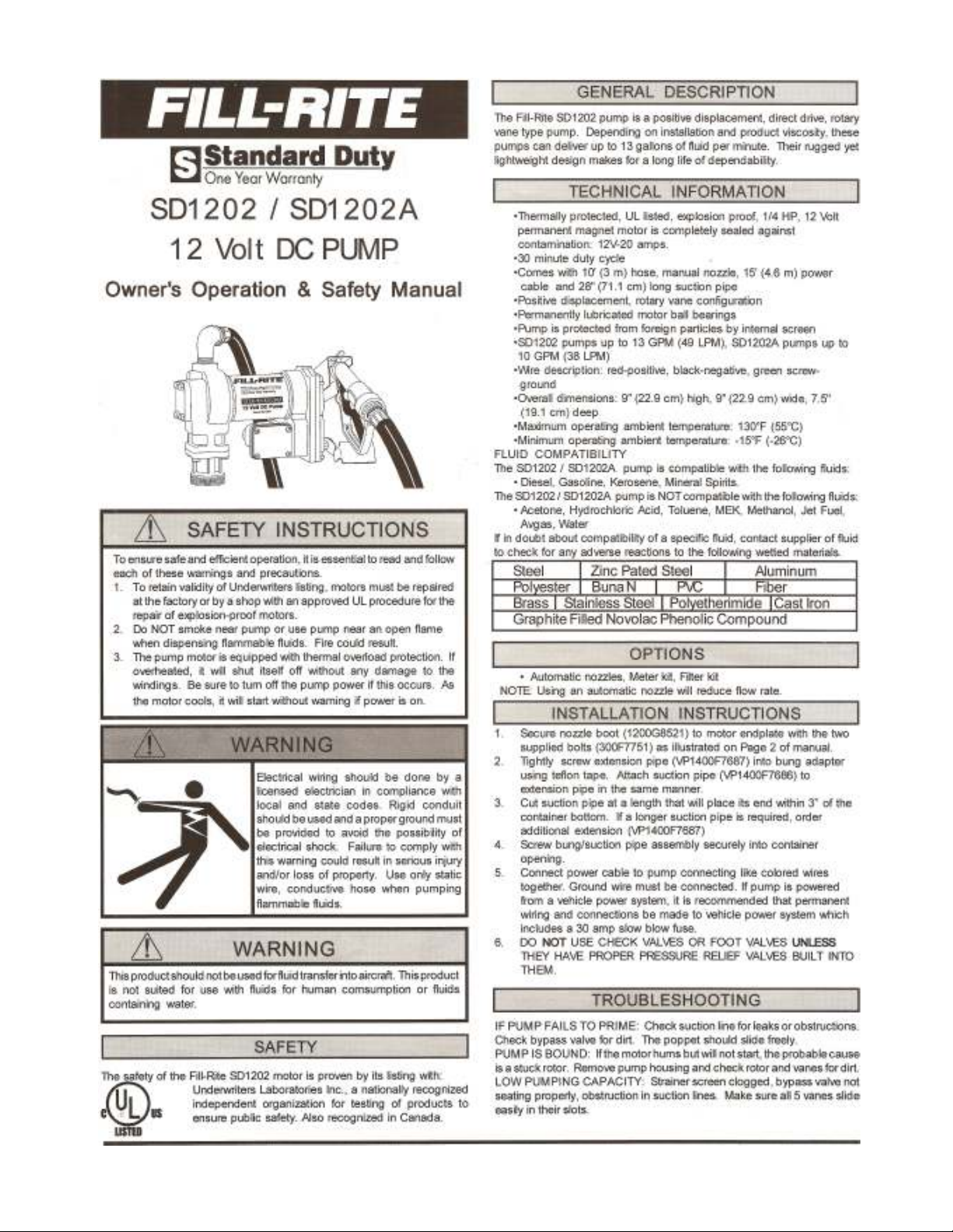
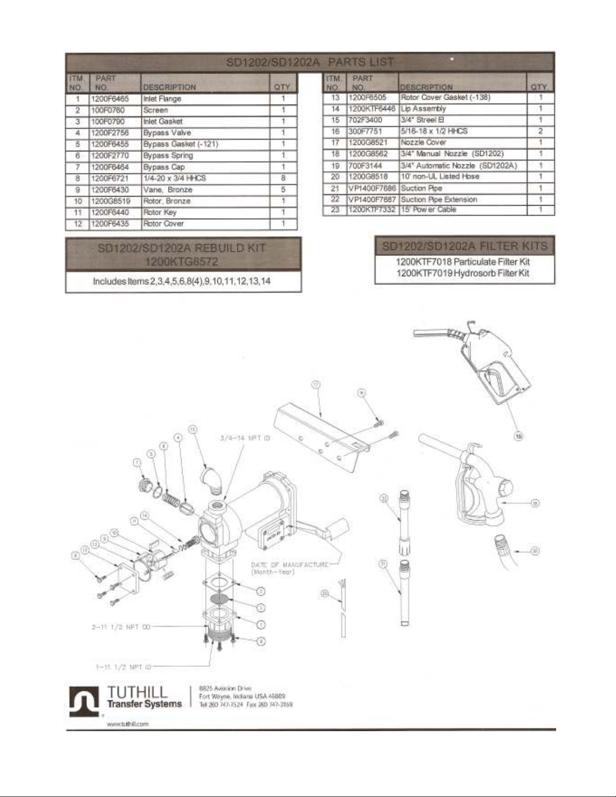
Auxiliary Fuel Pump……………………………………………………... 43 & 44
Automation Receiver Wiring Diagram…………..……………..………. 45
Safety Procedures………………………………..……..………………….1 to 3
Start-Up Electric Motor………………………….……….……………… 5
Hydraulic System……………………………..…...….……...…………… 6
Adjusting The High Speed Bypass………….…………………………… 9
Adjusting Pressure Switches……………….…………………….………. 10
Standard Speed Hydraulic Schematic…….…………………….………. 11
High Speed Hydraulic Schematic………….…………………….………. 12
Standard Speed Valve Assembly……………..………………….………. 13 & 14
High Speed Valve Assembly………………………..…………….………. 15 & 16
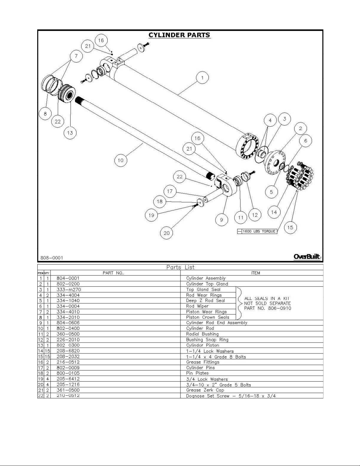
Cylinder Parts……………………………....…………………….………. 19
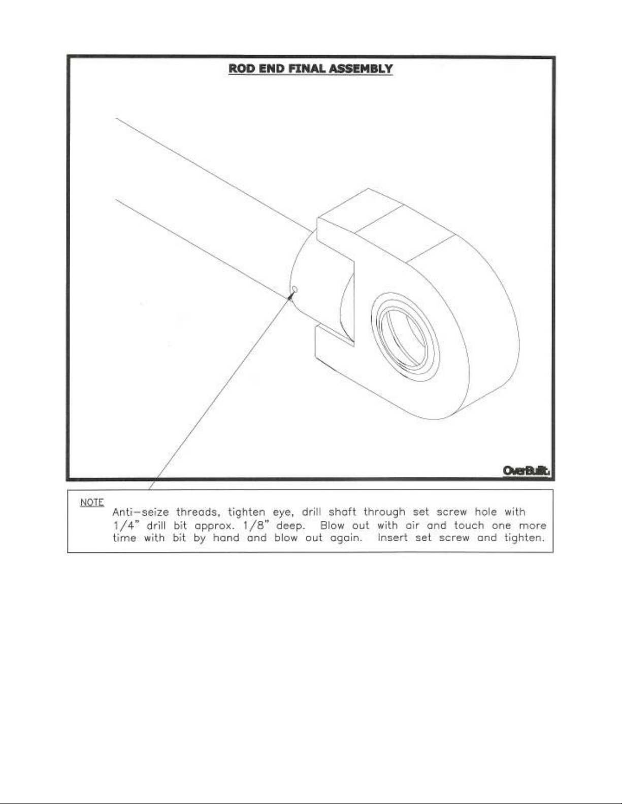
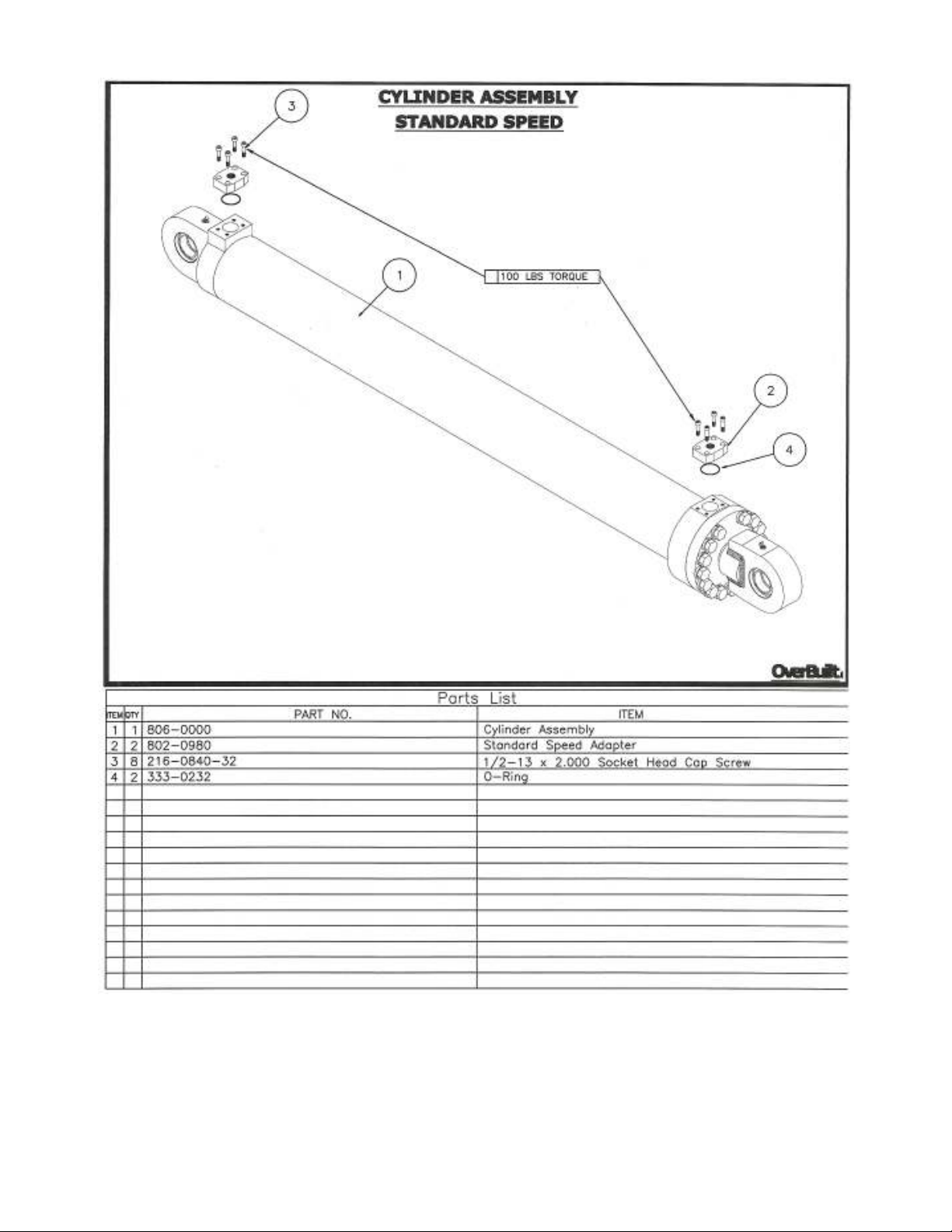
Cylinder Assembly Standard Speed..……....……………..…….……….. 22
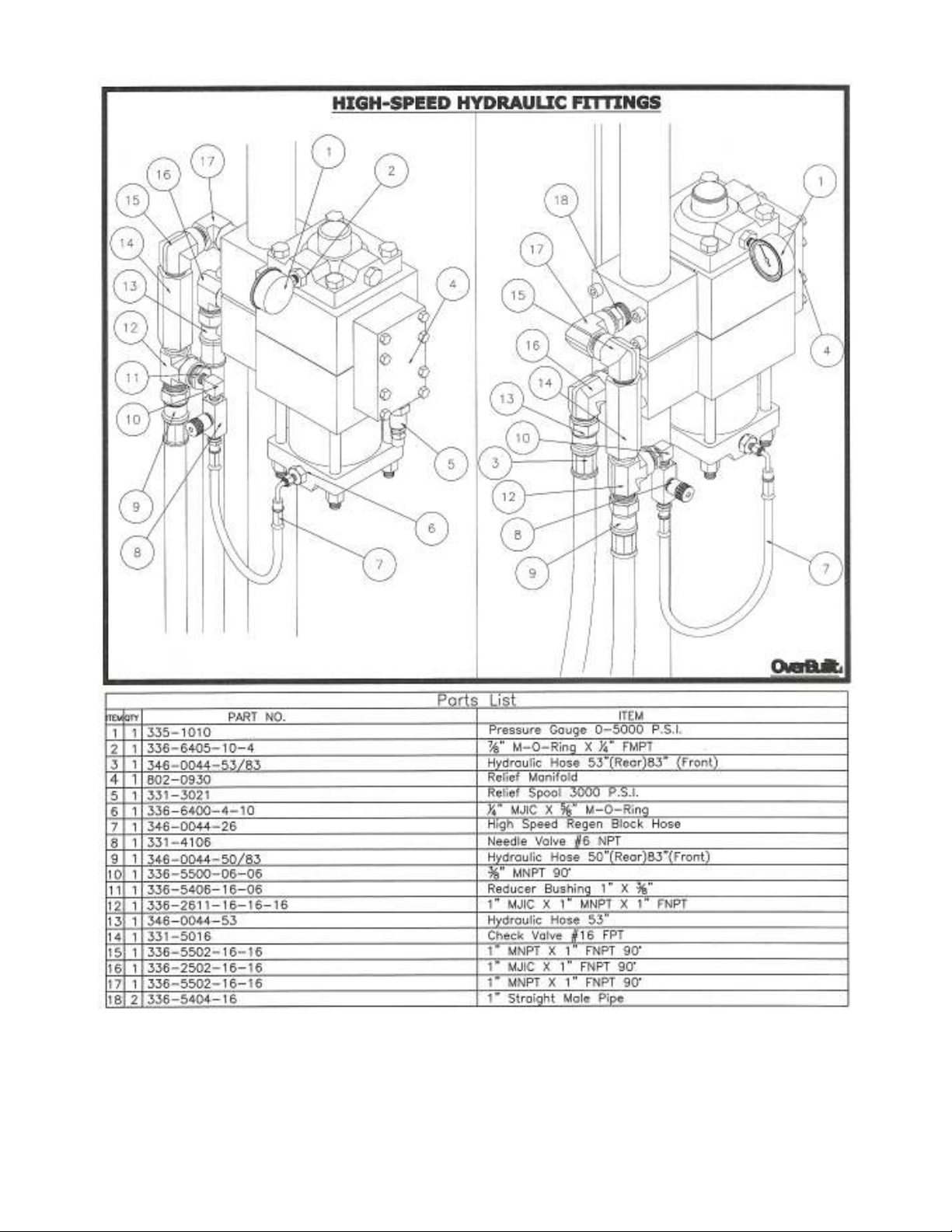
High Speed Hydraulic Fittings.………..…..………………….…………. 24
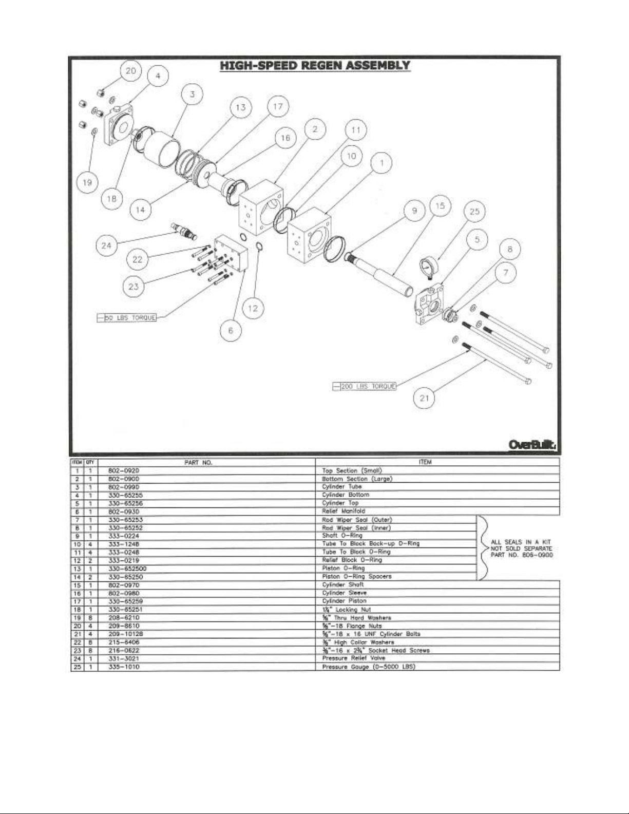
High Speed Regen Assembly.…………..…..………………….…………. 25
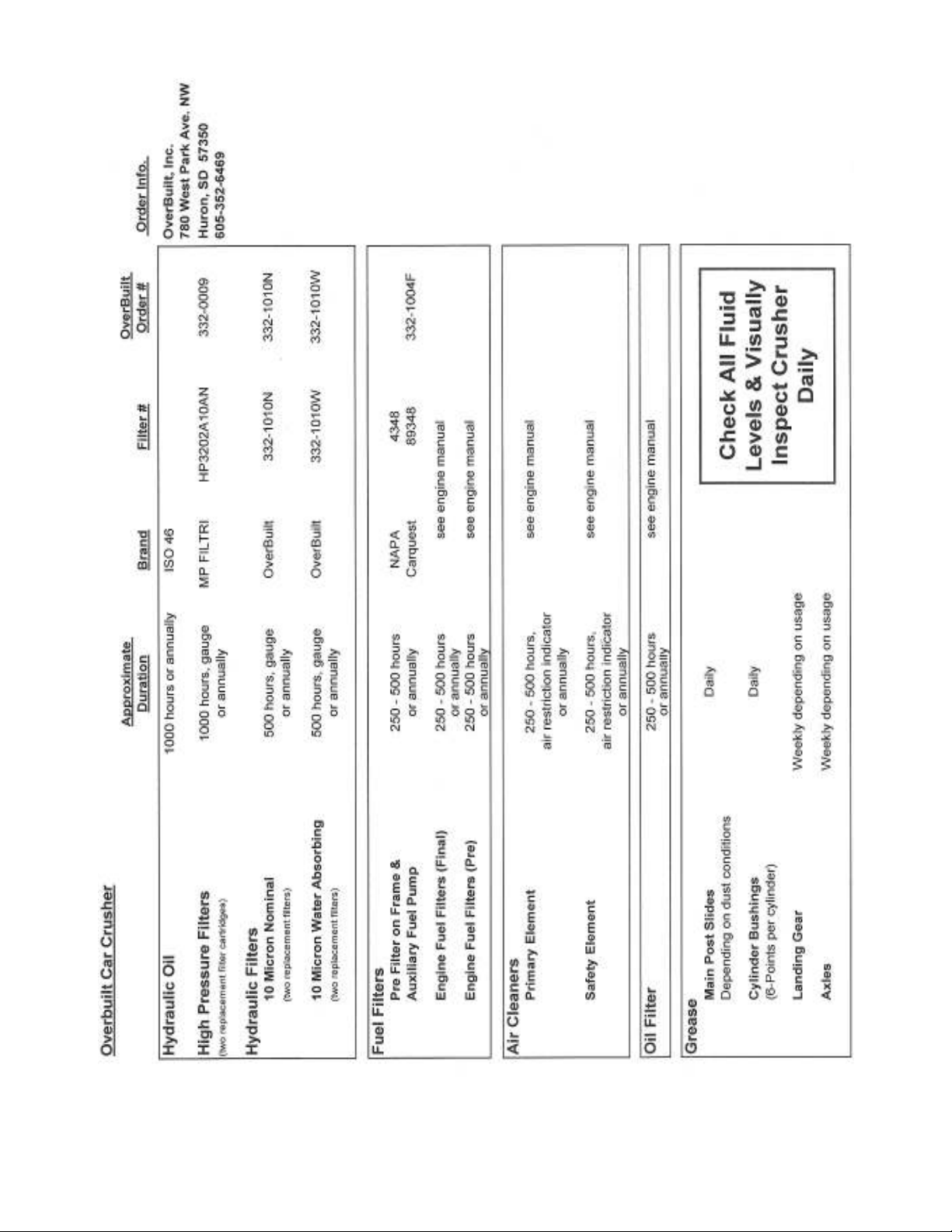
Crusher Filters & Lubrication……..…..……………….…….…………. 26
Advanced Oil Recovery System……………………………..…………… 31
Receiver/Transmitter Programming………………….…….…………… 33
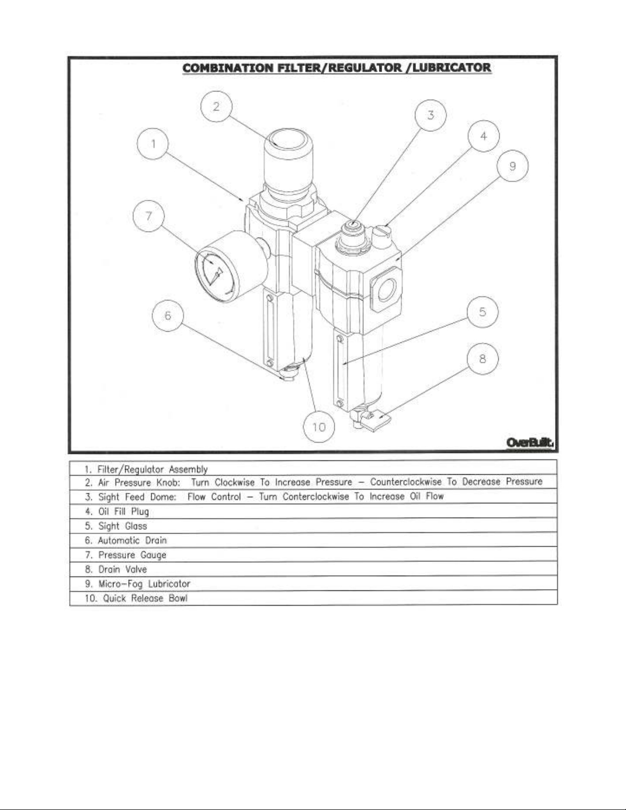
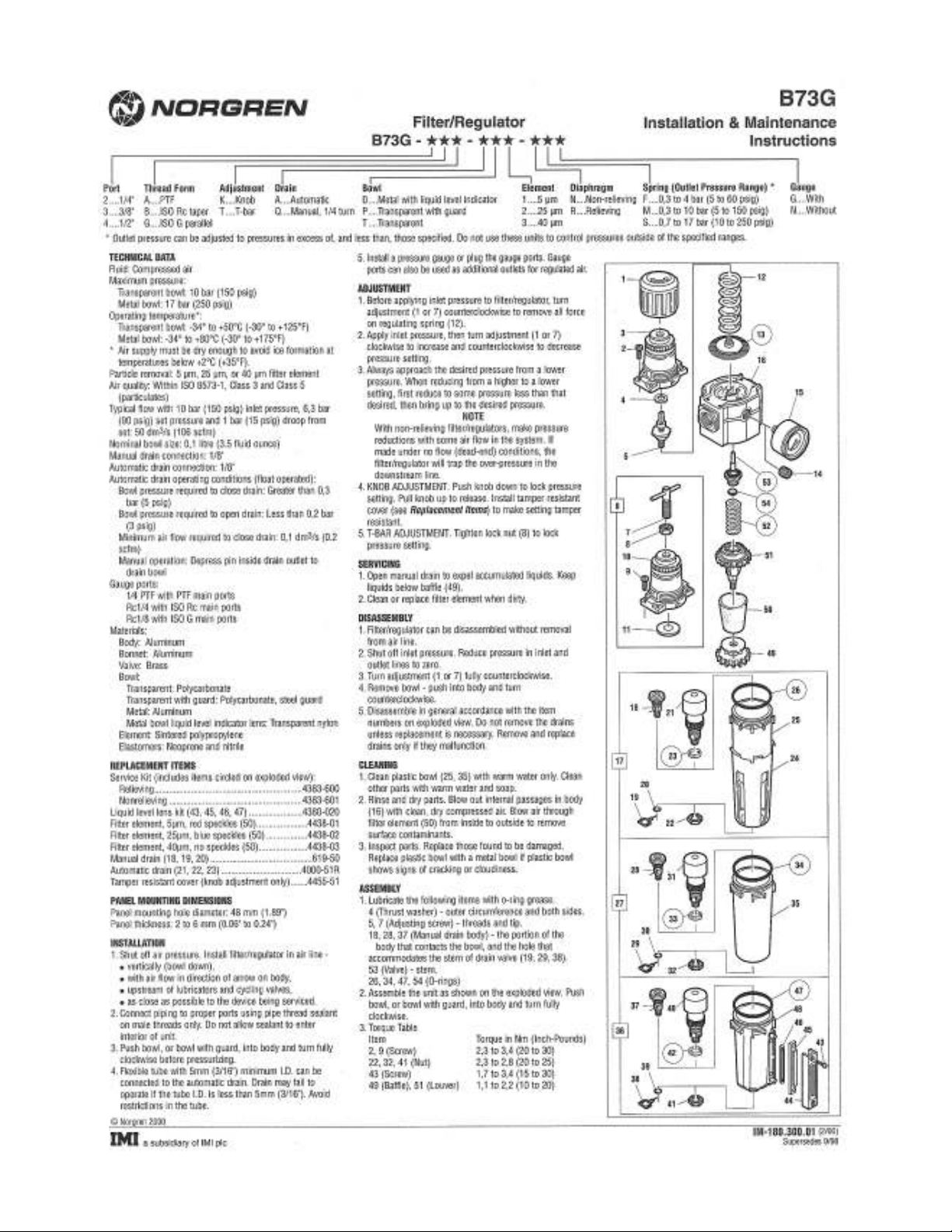
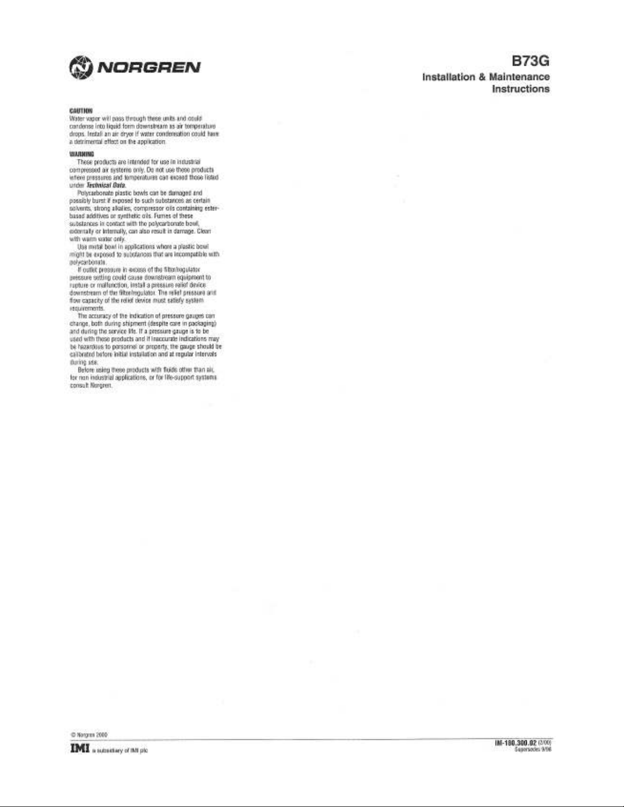
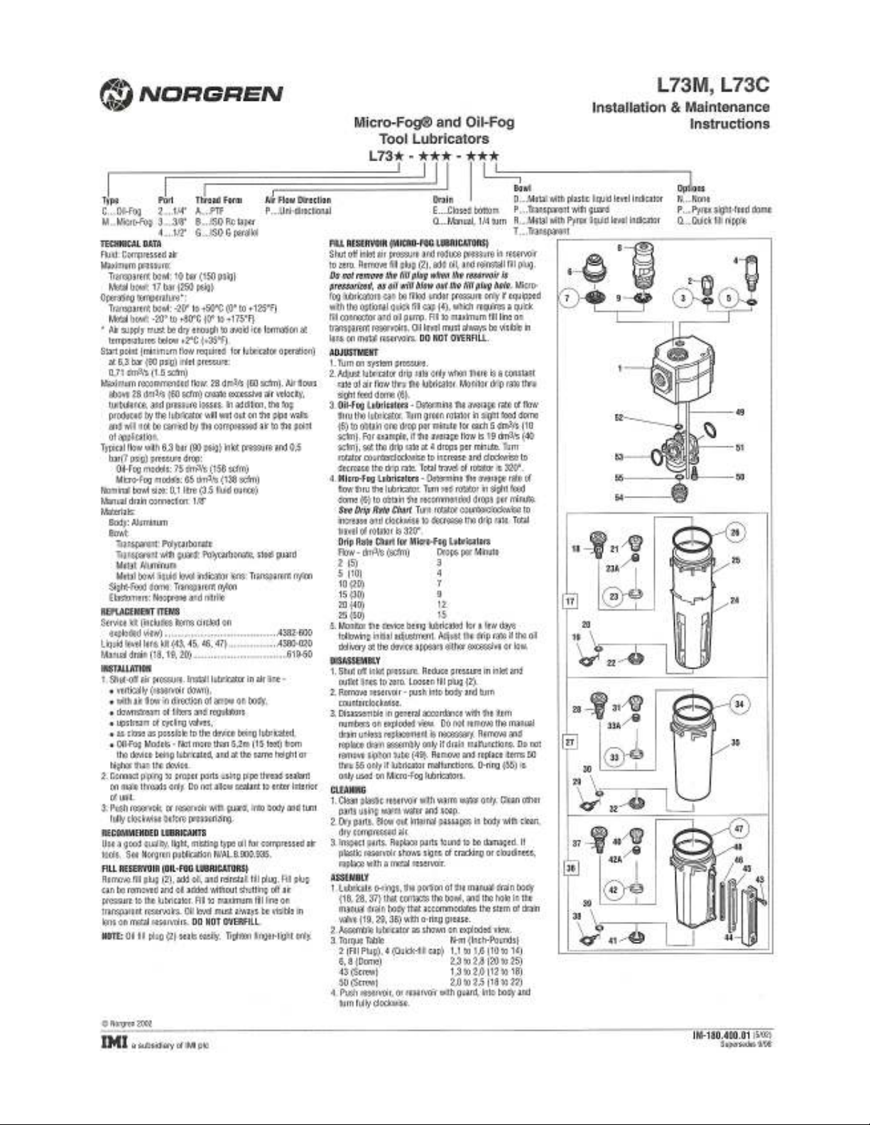
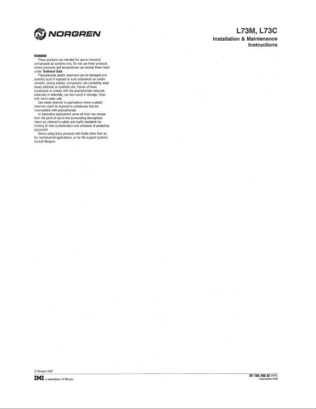
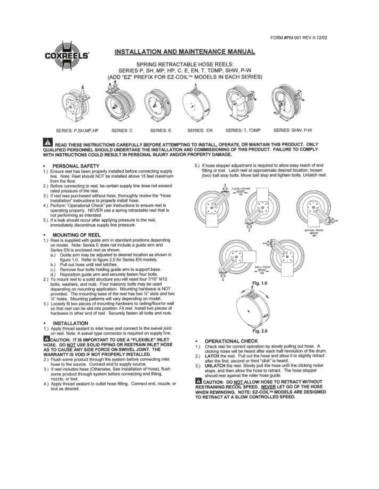
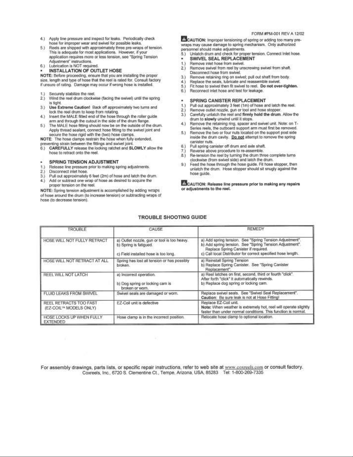
Combination Filter/Regulator/Lubricator…………………….………... 34 to 42
Trouble Shooting…………………………….…………….……………… 46 & 47
Warranty……………………………..……………………….…………... 48
Page 3
Safety
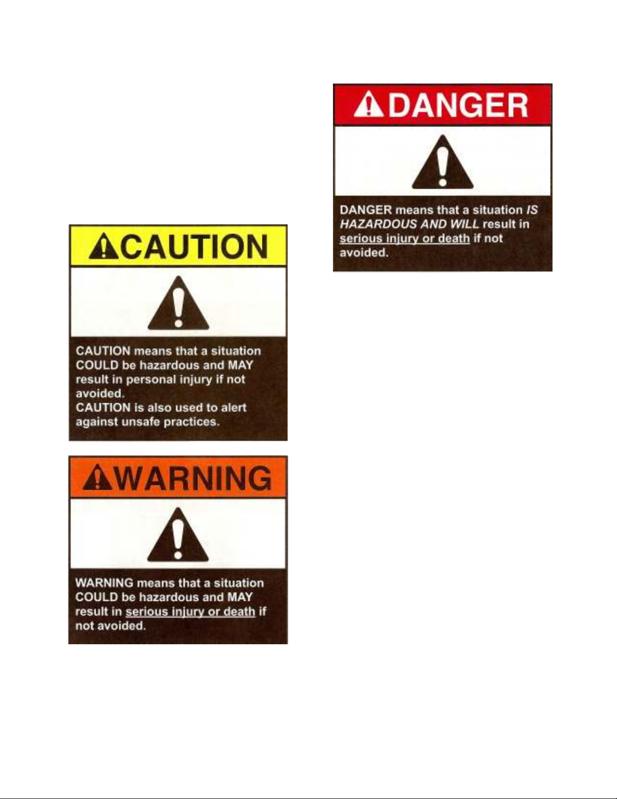
CAUTION, WARNING &
DANGER: WHAT THEY MEAN
Hazards are identified by the “Safety Alert
Symbol” and followed by a signal word:
Caution, Warning or Danger.
DECALS
The decals on the machine provide instruction
for safe and correct operation.
Never make modifications affecting the safe
operation or capacity without the expressed
written approval of OverBuilt, Incorporated.
When OverBuilt approved modifications are
made, the user is responsible for seeing that
appropriate decals and instructions are
changed.
All plates and decals must be in place and
legible at all times.
OPERATOR QUALIFICATIONS
AND TRAINING
⇒⇒⇒⇒ Only trained and authorized persons
should operate the machine. To be
qualified, you must understand the
written instructions supplied by the
1
manufacture, have training (including
the actual operation of this machine)
and know the safety rules and
regulations of the job site.
⇒⇒⇒⇒ Do not operate the machine until you
fully understand the function of all
controls, indicators and instruments.
Page 4

n
should be used at all times when
operating or standing near the
IMPORTANT
EYE AND EAR PROTECTION
Safety glasses and ear protectio
crusher.
Safety Devices
Valves are enclosed in a lockable cabinet.
This allows you to secure the valves from
unauthorized or unintentional use.
Safety lock can be placed on both ends of
the crusher. They are located on the uprights
and must be manually placed under the slides.
To lock the lid in the upright
position.
Make sure the top lid is all of the way up.
Remove the yellow safety lock located on
the uprights.
Place the lock under the lid slides.
Repeat on the other end.
The top lid is now blocked from falling.
NOTE: This safety lock is to prevent the top
lid from falling under its own weight. It may
not stop the lid from falling if you apply
downward hydraulic pressure to the cylinders.
Putting downward hydraulic pressure
on the lid with one or both of the safety
lock mechanisms in place may damage
the mechanisms or a cylinder rod.
Remove keys and do not run engine
when the safety locks are in place.
Always inspect the safety locks to
make sure they have not been damaged.
LOCKOUT PRECEDURE
Crusher lid may fall and death or serious
injury will occur if the following precautions
are not observed before getting on or into
the crusher:
1. Raise lid to full height.
2. Shut off crusher engine and remove
key.
3. Lock cabinet containing hydraulic
valves and remove key.
4. Carry all sets of keys with you.
5. Remove the yellow safety lock located
on the uprights.
6. Place the safety lock under the lid
slider.
7. Repeat on the other end.
8. When finished, remove safety locks
before lowering the lid.
Important: Never leave the crusher lid in a
raised position while the crusher is
unattended.
CRUSHER LOCATION
Lid rises higher than the frame of the
machine. Operating this equipment near
or below power lines may cause serious
injury or death.
Machine should be positioned on level
hard ground.
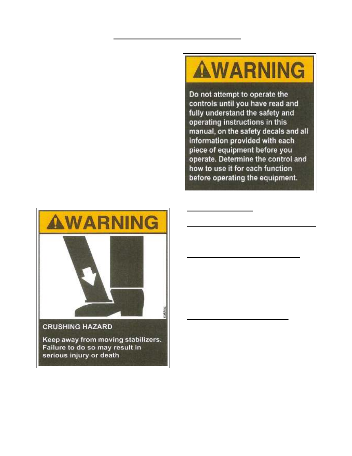
Never move crusher unless the crushing
chamber is completely empty and the
crusher lid is in the closed position.
2
Page 5

Safe Operation of this crusher is the operator’s responsibility. Listed below are some basic
rules that can make an operator aware of dangerous practices to avoid and precautions to take
for his own safety and the safety of others. Observance of these rules in addition to frequent
examinations and periodic inspections of the equipment may prevent injury to personnel and
damage to equipment.
• 1. DO study this manual before operating the crusher. If your crusher is equipped with a remote
control, refer to that part of the manual for additional precautions.
• 2. DO make sure that all persons stay clear of the crusher during operation.
• 3. DO promptly report any malfunctions, unusual performance, or damage of the crusher.
• 4. DO inspect the crusher regularly, replace damaged or worn parts, and keep appropriate
records of maintenance.
• 5. DO inspect the hydraulic system for leaks, worn or damaged hoses.
• 6. DO inspect the fluid levels prior to starting the engine.
• 7. DO keep the crusher clean, paying special attention to the electrical and hydraulic systems.
• 8. DO immediately repair or replace any worn or damaged parts prior to operating the
crusher.
• 9. DO follow the LOCKOUT PROCEDURE (see page 1) prior to getting on or in the crusher.
• 10. DO lower the lid and shut off the engine prior to doing maintenance on the crusher.
• 11. DO NOT at anytime get in or reach in the crusher chamber while the engine is running. The
lockout procedure must be strictly followed.
• 12. DO NOT operate the crusher without visually inspecting in and around the crusher for other
personal.
• 13. DO NOT operate the crusher unless you have a clear view of the machine.
• 14. DO NOT reach in or across moving parts.
• 15. DO NOT operate the crusher near or under power lines.
• 16. DO NOT move the crusher unless the crushing chamber is completely empty and the lid is in
the down position.
• 16. MOST OF ALL use common sense when operating this or any other piece of equipment.
Safety on the job begins with you
3
Page 6
START-UP – DIESEL ENGINE
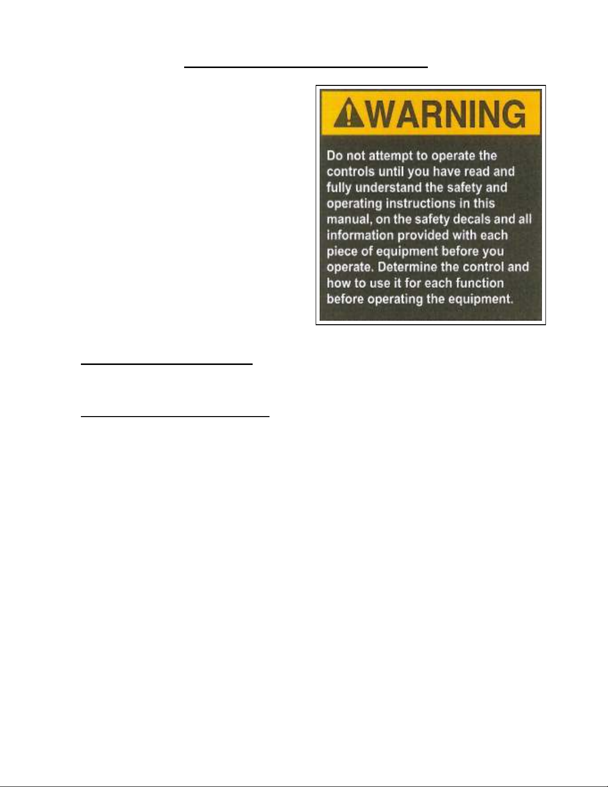
Before starting the engine, read the
manufactures engine operator’s manual.
Check all fluid levels, engine oil, coolant and
hydraulic reservoir.
Turn the ignition key until the starter engages.
Allow the engine to warm up for a couple of
minutes.
Flip the throttle toggle switch to run at high
RPM.
You are now ready to run the lid up and down.
Raise the lid by pulling the valve handle
toward you.
Lower the lid by pushing the valve handle
away from you.
NOTE: Operate the crusher manually to get
familiar with it and to test its operation prior to
using the remote control.
Although the machine was tested at the factory
it is always a good idea to check for oil leaks.
Crank Landing Gear: Block the front of the
machine with a railroad tie. The Manual Crank
Landing Gear Is For Transportation Use Only.
Using it to stabilize the machine while
crushing may cause damage.
Hydraulic & Manual Landing Gear: Pull
safety pins on landing gear legs. Adjust the
landing gear to the desired height using the
hydraulic valves (if so equipped) or manually
using an appropriate sized jack or the air
system on the semi-tractor. Replace safety pins
when you are done adjusting legs.
COLD WEATHER STARTING: 1. Start
diesel engine and run at idle for 5 – 10
minutes. 2. Turn high idle switch on to
help circulate oil through pump. 3. Move lid
up and down manually or with switches on
transmitter (hand held) to help warm hydraulic
oil.
Note: Allow at least 30 minutes for steps 1–3.
4
Page 7
START-UP – ELECTRIC MOTOR
Before starting the engine, read the
manufactures motor installation and
maintenance manual.
Check the fluid levels of the hydraulic
reservoir.
Push the start button to engage the motor
Check motor rotation.
Check the power plant for leaks or other
problems.
You are now ready to run the lid up and down.
Raise the lid by pulling the valve handle
toward you.
Lower the lid by pushing the valve handle
away from you.
NOTE: Operate the crusher manually to get
familiar with it and to test its operation prior to
using the remote control.
Although the machine was tested at the factory
it is always a good idea to check for oil leaks.
COLD WEATHER STARTING: 1. Start electric motor and run for 5 – 10 minutes to help
circulate oil through pump. 2. Move lid up and down manually or with switches on transmitter
(hand-held) to help warm hydraulic oil. Note: Allow at least 30 minutes for steps 1 and 2.
MANUAL/AUTOMATIC SWITCH: Operating the crusher in the manual position deactivates
the 20-minute safety shutdown timer (for cold weather warm up) and the remote start/stop
function from the transmitter. When the crusher is operating, turn the switch to auto to activate
the 20-minute safety timer and the remote start/stop feature.
5
Page 8
6-1 THE HYDRAULIC SYSTEM
There are really two separate hydraulic
systems. The hydraulic tandem pump contains
two sections that draw oil from the tank through
two 100-mesh screen filters located inside the
tank. Each section pumps oil into one of the two
4-way control valves. The valves can be
electrically or manually controlled. The two
valves, in turn, control two separate 10” cylinders.
To raise the lid, pull the valve handle
toward you, oil is then sent to the bottom port of
the cylinder, which will force the lid to go up. The
oil in the top of the cylinder is sent through a 10micron filter and then to the tank
To lower the lid, push the valve handle
away from you, oil is then sent to the top port of
the cylinder, which will force the lid down. The
oil in the bottom of the cylinder is sent through a
10-micron filter and then to the tank.
When the valve handles are in the center
position oil is sent through a 10-micron filter and
then back to the tank.
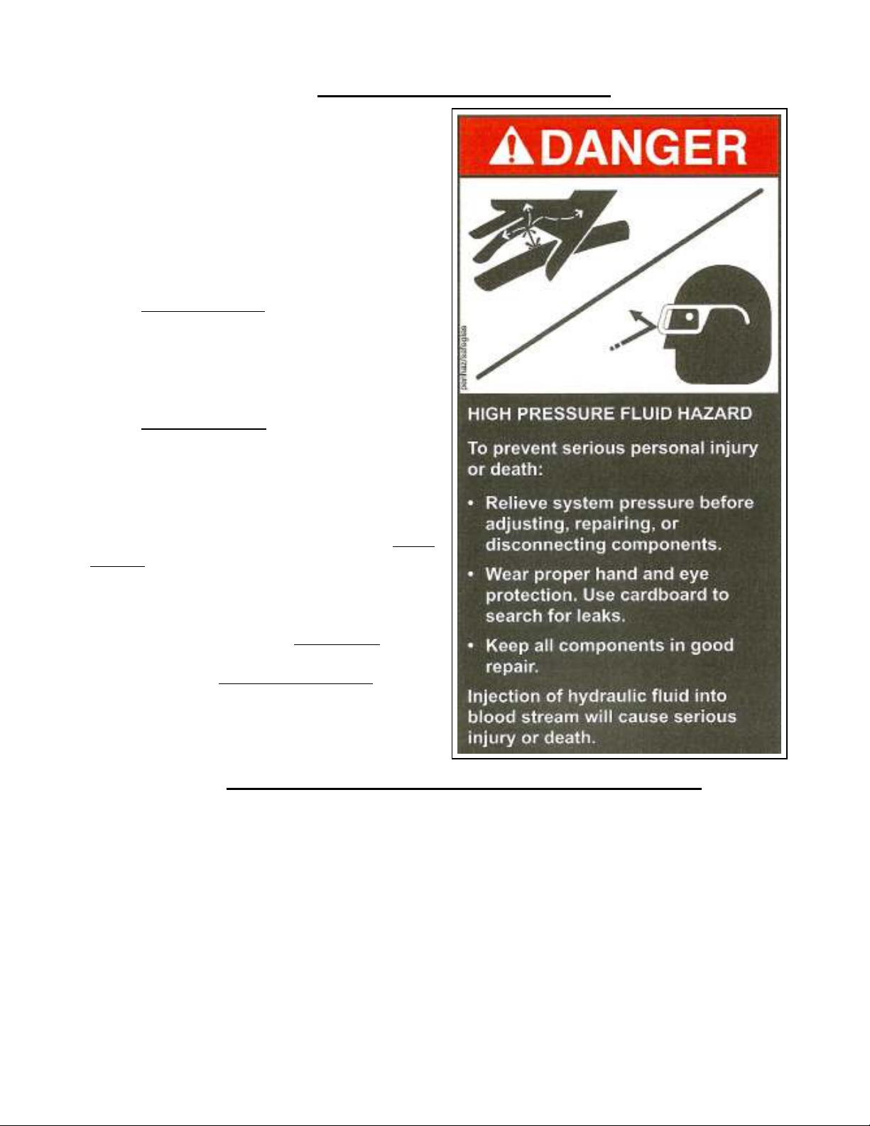
There are two safety pressure valves
located on each system. A Main Relief on the
control valve restricts the valve operating pressure
to 2600 psi. The Cylinder relief valves restricts
the cylinder operating pressure to 2800 psi and
protects the cylinders from extreme pressures that
could damage them.
6-2 STANDARD SPEED CYLINDER OPERATION
On our standard hydraulic system, to raise the lid we pump 32 gallons of oil into the bottom
of each cylinder. The 27 gallons of oil in the top goes back to the tank. The 5-gallon difference is
equal to the area of the rod.
To lower the lid we pump 27 gallons of oil into the top of each cylinder. The 32 gallons of oil
in the bottom goes back to the tank.
6
Page 9

HIGH SPEED CYLINDER OPERATION
It is important to understand the principle of how your high-speed crusher works. If you are
new to this type of equipment you should run the lid up and down a few times to get acquainted with
it. You will find it is totally different than standard speed crushers.
The speed is achieved through the use of 2-1\2” oil bypass valves (Please see illustration on
page 24) located on the main cylinders. It’s quite simple; a cylinder is always full of oil. The bypass
system transfers that oil between the top and bottom cylinder ports, eliminating the need to send oil
all the way back to the tank. The oil is transferred directly to the other end of the cylinder. This
means to raise or lower the lid we only need to move 5 gallons (rod area) of oil in or out of each
cylinder, not the full 32 gallons like the standard system
To raise the lid we take the 27 gallons of hydraulic oil that is in the top of the cylinder and
transfer it to the bottom through the 2.5” bypass valve, adding only 5 gallons of oil from the pump.
Now in about 8 seconds we have put 32 gallons in the bottom of the cylinder. Putting our actual
cylinder port oil flow at over 200 gallons per minute.
When you lower the lid, the oil in the bottom of the cylinder transfers to the top through the
bypass valve. Since there is more, oil in the bottom than the top only the excess 5 gallons goes back
to the tank. It will retract the full 8 feet in just 8 seconds. Putting our actual cylinder port oil flow at
over 200 gallons per minute.
When you raise the lid the bypass valve opens automatically, giving you high-speed operation
on the full up stroke.
The length of time the lid falls in high-speed mode is adjustable. When you lower the lid the
bypass valve will start to close, you can adjust how long it takes the valve to close using the needle
valve (Please see instructions on page 9 – illustration on 24 part # 8) located on the bottom port of the
bypass valve.
As an example you could set it to close in 4 seconds, this means the top lid will lower about 4
feet in the high-speed mode. After the valve closes the lid will slow to the standard speed.
If the lid can fall only 2 feet before landing on the load, it will just sit there for the additional
2 seconds until the valve closes, and then the crusher lid will operate at standard speed and pressure.
AGAIN: When the lid is coming down, you can adjust how far you want it to fall in the highspeed mode. Using the needle valve to adjust the time is takes for the valve to close. Once closed the
cylinders work at standard speed and pressure.
NOTE: During the down stroke, the cylinders do not operate at high pressure in the highspeed mode. Only when the bypass valve closes can the cylinders create high pressure.
You will create high pressure on the up stroke after the cylinders top out.
7
Page 10

ADJUSTING RELIEF VALVES
8-1 Main Relief
The main relief valves are located on the main control valves and are set at 2600 psi. The main relief
(Please see illustration on page 15 part # 5) will limit the amount of pressure that can be built up in
the system.
To check the main relief setting.
Lower the lid.
Push the valve handle away from you to build pressure.
The valve needs to be all of the way open.
Read the pressure gauge on the valve.
This pressure is the main relief pressure and should read 2600 psi.
To adjust the pressure, follow these steps. You will need a 3/4-inch wrench and a 1/4-inch Allen
wrench. - The valve adjustment is located on the back-left side of each control valve.
Remove the dust cap with ¾ inch wrench.
Loosen the nut with ¾ inch wrench.
Hold the valve all the way open.
To adjust the relief to 2600 psi, turn it with a 1/4-inch Allen wrench.
Turn in (clockwise) to increase pressure.
Turn out (counterclockwise) to decrease pressure.
Tighten the nut while holding the Allen wrench in place to keep the setting from changing.
Check the setting after the nut is tight, in some cases it will have changed and you will have to
adjust a second time.
8-2 Standard Speed Cylinder Relief
The cylinder relief valves are located on the back of the main control valves and should be set at 2800
psi. (Please see illustration on page 13 part # 14)
This relief allows the cylinder to extend during the rock cycle, when the opposite end is pulling down
and teeter-tottering the lid over the load
As long as the main control valve can achieve 2600 PSI the bypass won’t need to be adjusted
To adjust the pressure, call the Factory.
8-3 High Speed Cylinder Relief
The cylinder relief valves are located on the side of the bypass valve and should be set at 2800 psi.
(Please see illustration on page 24 part # 5)
This relief allows the cylinder to extend during the rock cycle, when the opposite end is pulling down
and teeter-tottering the lid over the load
As long as the main control valve can achieve 2600 PSI the bypass won’t need to be adjusted
To adjust the pressure, call the Factory.
8
Page 11

ADJUSTING THE HIGH SPEED BYPASS VALVES
A needle valve (Please see illustration on page 24 part # 8) is located next to the bypass valve on each
cylinder. It controls the oil flow into the pilot port of the bypass valve. Therefore controlling the
length of time it takes the bypass valve to close.
Watch the bypass valve open and close
You can actually see the valve open and close by watching the plunger on top of the bypass valve.
When the plunger is up the valve is closed.
When the plunger is down the valve is open.
Again when the bypass valve is open (the plunger is down) the lid comes down in high-speed mode.
Once closed (the plunger is up) the lid will fall at standard speed and pressure. Slowing the oil flow
into the valve will lengthen the time it takes to close, thus increasing the distance the lid will fall in
the high-speed mode.
How to adjust.
To Increase the distance the lid falls at high speed; turn the needle valve in (clockwise) which will
increase the time it takes to close the bypass valve.
To Decrease the distance the lid falls at high speed; turn the needle valve out (counterclockwise) to
decrease the time it takes to close the bypass valve.
The bypass valves are set at the factory to close in 3-4 seconds.
This means the lid will fall about 3-4 feet in the high-speed mode. Then switch to standard speed and
pressure for the last 4-5 feet.
On the first and second cars, the lid will slow to standard speed prior to hitting them. As the pile of
cars gets taller the lid will make contact with them in the high-speed mode.
Example: If the lid only falls for 2 seconds before hitting the load, it will just sit there until the valve
closes. In this example it will sit for an additional 1-2 seconds. After the bypass valve has closed the
cylinders will operate at standard speed and pressure.
It is completely normal for the crusher lid to stop for a few seconds on any load that is taller than 6
feet.
Important: If your crusher is equipped with a remote control, changing the factory setting will effect
how the rock cycle works. If you increase the distance that the lid falls you must increase the height
of the rock cycle. (Please see illustration on page 33 or call the factory prior to making adjustment)
9
Page 12

Adjusting Pressure Switch
Pressure switches are used to send 12V DC signals to the microprocessor. The remote control uses
hydraulic pressure to tell when one step of the cycle is ended and another needs to start.
To adjust the pressure switches follow these steps. You will need a flat screwdriver.
Note: There are indicator lights on the receiver (white box) that tells you when each pressure switch
is closed. The left one is for the left valve, the right one is for the right valve.
1. Lower the lid.
2. Turn the receiver on.
3. With the lid down push the valve handle away from you and hold, this will allow the
maximum pressure of 2600 psi* to be achieved, then release handle. Each pressure switch is
wired to an indicator light on the receiver box. This light will tell you when the pressure
switch is closed.
4. Slowly push the valve handle away from you and watch the pressure on the gauge. You can
tell what pressure the switch is set at, by looking at the pressure reading on the gauge when
the light comes on. Important: Let the pressure on the gauge rise very slowly.
5. Set both pressure switches at 2400 psi. This means the light will come on at 2400 psi.
6. To adjust the pressure, loosen the setscrew (flat screwdriver) on the side of the adjustment
ring.
7. Twist the adjustment ring clockwise to increase the release pressure or counterclockwise to
decrease the release pressure.
8. Re-tighten the setscrew.
Loosen the setscrew Twist the adjustment ring Tighten the setscrew
• The gauge should read 2600 psi when the valve is fully open. If it does not, go to the Adjusting
Relief Valves section on page 8.
10
Page 13

11
Page 14
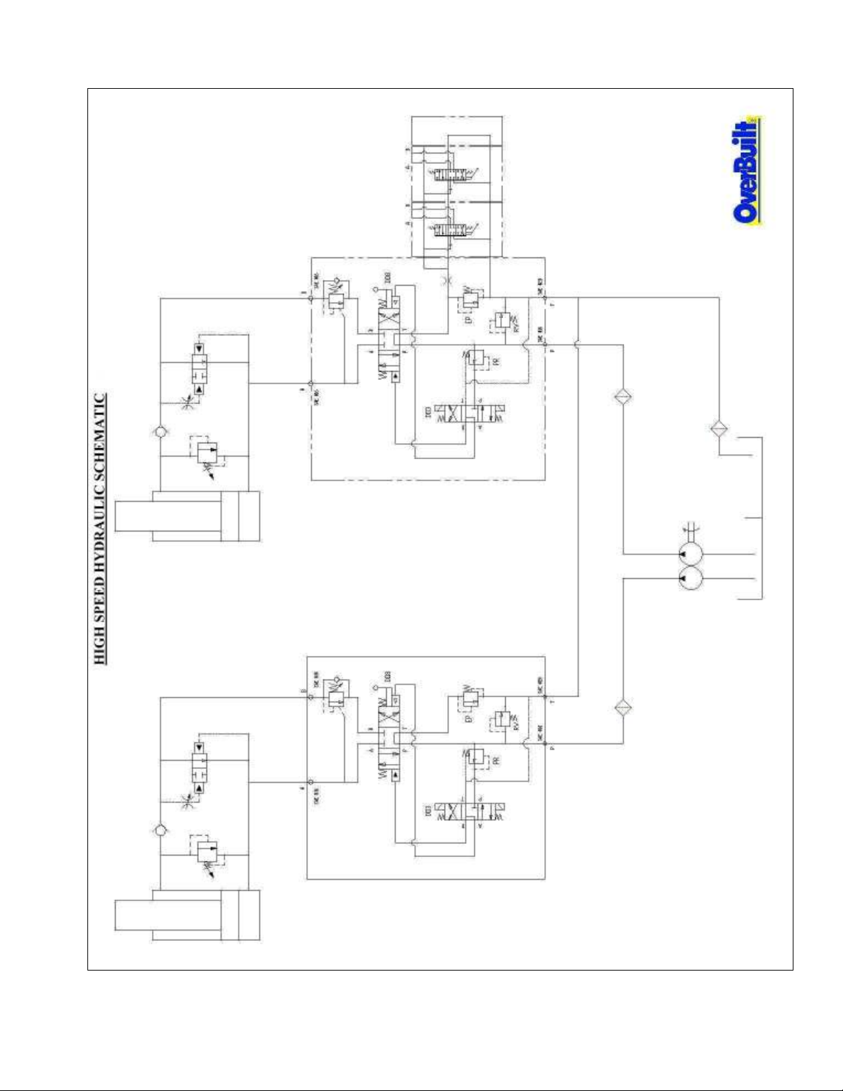
12
Page 15

13
Page 16
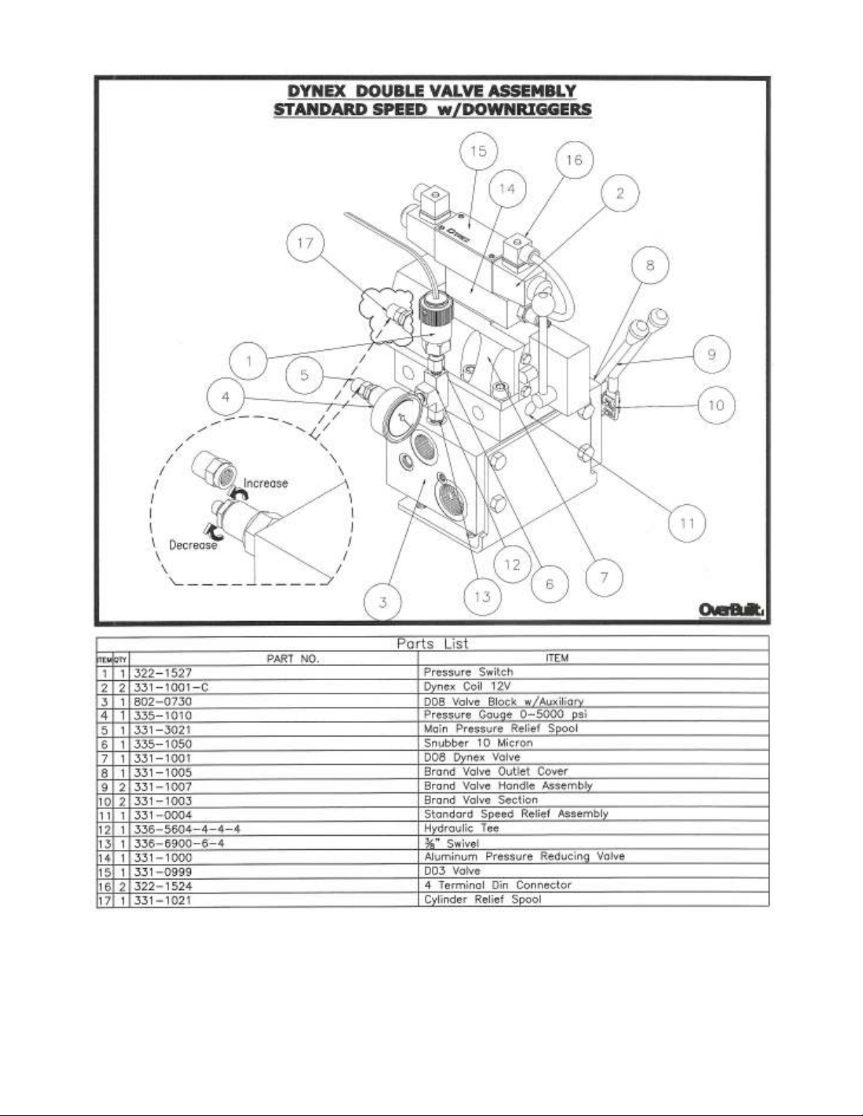
14
Page 17
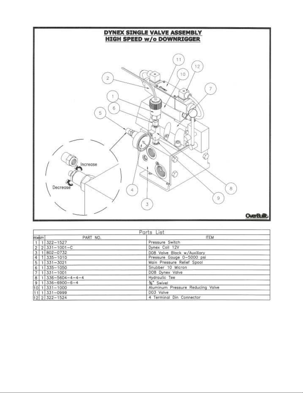
15
Page 18
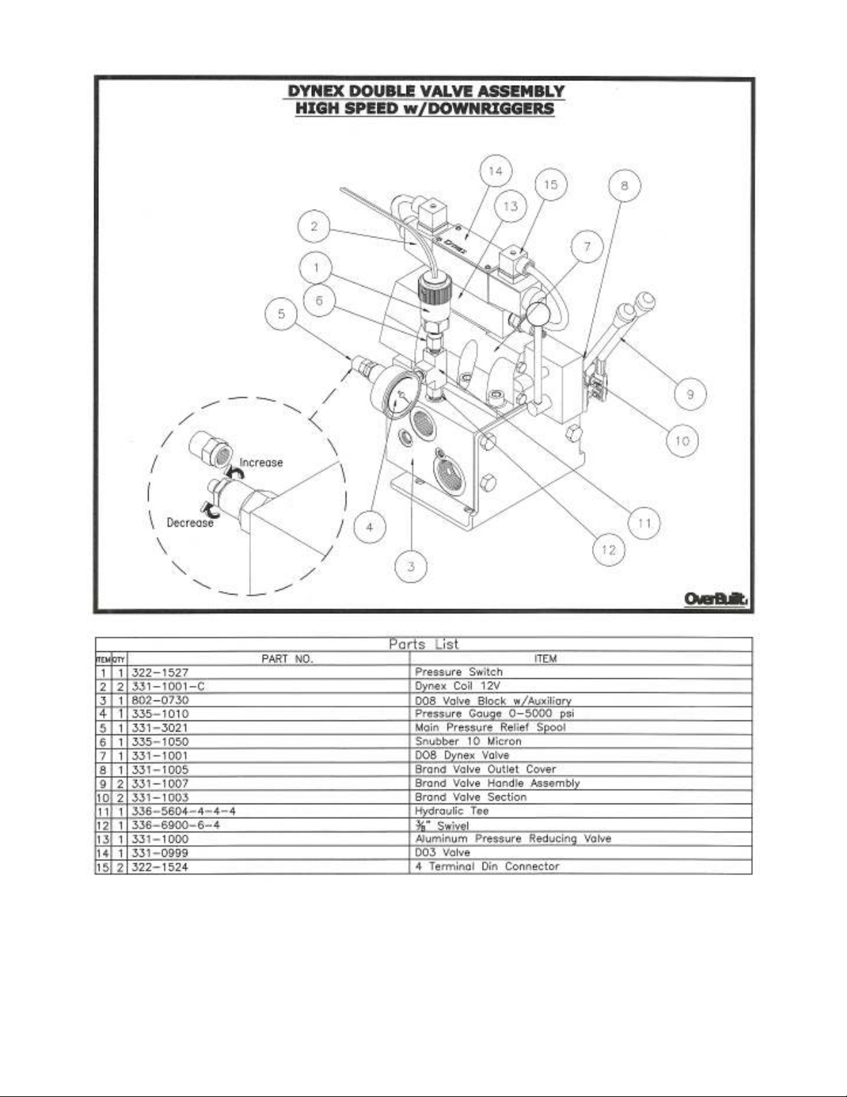
16
Page 19
17
Page 20
18
Page 21
19
Page 22
20
Page 23
21
Page 24
22
Page 25
23
Page 26
24
Page 27
25
Page 28
26
Page 29
27
Page 30
28
Page 31
29
Page 32
30
Page 33
31
Page 34
32
Page 35
33
Page 36
34
Page 37
35
Page 38
36
Page 39
37
Page 40
38
Page 41
39
Page 42
40
Page 43
41
Page 44
42
Page 45
43
Page 46
44
Page 47
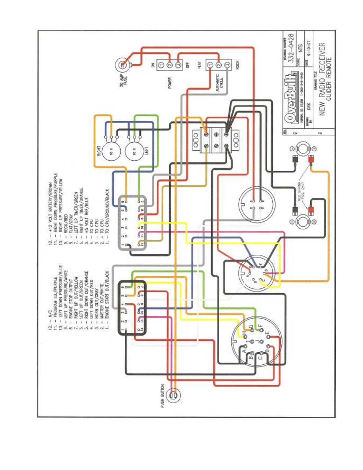
45
Page 48

TROUBLE SHOOTING
Symptom Problem Solution
Lid “tops out” cylinder on the Lid is missing micro switch arm. Adjust arm – side to side, up and
up stroke and the crusher down or rotate arm. (See page 32.)
continues to build pressure.
(Diesel engine will stay on Lid hits switch but does not stop. Check arm operation & electrical
high idle.) connection. (See page 18.)
Lid stops approximately 2 feet Micro switch arm hits the top Adjust load if the lid is coming off
from the top. of the lid instead of the stop tab. off an uneven bundle.
Adjust arm – side to side up and
down or rotate arm. (See page 32.)
Lid stops ¼ - ½ of the way up. Micro switch arm stuck in up Check arm alignment and it’s
position. movement up and down. (See page 32.)
Bad electrical connection. Check wiring inside of micro switch.
Disconnect two-pin connector to micro
switch to see if remote will lift lid with
automation system. (See page 18.)
Lid will not release to go back Automation system not receiving Check two pin electrical connection to
up on automated cycle. signal from pressure switch. pressure switch. (See page 18.)
Check connection to automation box
by jumping connection to white
automation box with wire or paper clip.
(The automation light should come on.)
Pressure switch setting too high. Decrease pressure by turning switch
adjustment counterclockwise. (See
page 10.)
Switch is plugged or stuck. Check and clean pressure switch and
snubber filter while tapping them to
loosen debris.
Light on the white automation Pressure switch setting too low. Increase pressure by turning switch
control box stays on all the time. adjustment clockwise. (See page10.)
Switch is plugged or stuck. Check and clean pressure switch and
snubber filter while tapping them to
loosen debris.
Wire harness or receiver is faulty. Swap the two pin electrical connections
going to the left and right switches. If
the same light remains on replace
receiver. (See page 18.)
46
Page 49

TROUBLE SHOOTING
Symptom Problem Solution
Cylinder takes a long time to Hydraulic oil contamination or Turn needle valve (See page 24 item 8.)
build pressure. (High-speed debris blockage does not allow counterclockwise to open all the way
crushers only.) high-speed plunger to set. and operate machine to clear system.
Watch plunger, in order for it to build
pressure it must be all the way up.
(The same height as the opposite side.)
Cylinder only builds 400-600 psi Will it build 2,400 – 2,600 psi by
going down. manually running the cylinders to the
top?
Bad cylinder relief or regen If it will build pressure up, it may be
manifold. a bad cylinder relief or regen manifold.
(See page 13, item 14 for normal speed
and page 24 for the high speed crusher.)
Bad valve relief or hydraulic If it will not build pressure up, it may be
pump. a bad valve relief or a pump problem.
(See pages 13-16, item 5.)
To check relief spool, take pressure off
of system and remove with a 1¼ inch
wrench. Check plunger and o-rings.
The red automation transmitter Low charge or dead battery. Replace or charge battery.
light blinks or goes dead. (See Automation Manual.)
The automation transmitter Automation system may have Make sure that both the receiver and
will not operate the machine. lost transmitter code. the transmitter power are on and
program as instructed on page 33.
During a rock cycle the lid lifts The high speed plunger has not The lid should not free fall more than
up on one side while the other set, allowing fluid to bypass. 3 to 4 feet. Turn needle valve counterside pulls down. clockwise to decrease fall distance.
(See page 9 & diagram on page 24.)
The crusher battery is rundown Battery may have gone bad or Make sure ignition is off and that white
or dead. switch was left on. automation box is shut off at end of day.
Test crusher battery and replace as
necessary.
47
Page 50

OverBuilt, Inc.
780 West Park Ave. NW
Huron, SD 57350
LIMITED NEW EQUIPMENT WARRANTY
a. OverBuilt, Inc. warrants solely to purchaser (“Purchaser”) of the OverBuilt, Inc. new equipment (“Equipment”) that for a period of 1-year (Warranty
Period) commencing on the date of delivery. The equipment shall be free from defect in material and workmanship (“Warranty”).
b. In the event of the failure of the Equipment to comply with the warranty Period and in the event Purchaser gives OverBuilt, Inc. written notice of the
Equipment defect in material or workmanship within One (1) month after such defect occurs, then Purchaser’s sole and exclusive remedy and
OverBuilt, Inc. sole obligation shall be that OverBuilt, Inc. shall, at its sole cost and expense, correct all such defects in material and/or workmanship
by, at its option, repairing, replacing or modifying the Equipment to comply with the Warranty. Any such repairs, replacement, or modifications of the
Equipment, in whole or in part, shall not in any way extend the Warranty Period. Purchaser shall be required to obtain from OverBuilt, Inc. prior
authorization when the Equipment is returned to OverBuilt, Inc.
c. Not withstanding anything to the contrary contained within, in no event shall: (1) cost borne by OverBuilt, Inc. for such repair, replacement or
modification of any Equipment exceed the Equipment purchase price paid by Purchaser for the Equipment: or (2) OverBuilt, Inc.’s liability to Purchaser
or any third party for damages of any nature, including, without limitation, injury to any person or property, whether based on contract, tort, warranty,
strict liability or any other theory, exceed the Purchase Price of the Equipment.
d. This warrant does not cover any Equipment defect occurring: (1) from normal wear and tear: (2) in shipment to or from Purchaser: (3) due to force
majeure, improper installation or maintenance, misuse, abuse, neglect, accident, negligence, mishandling, lack of maintenance or reasonable care, or any
other cause other than ordinary commercial application, by Purchaser or any third party (other than OverBuilt, Inc. or OverBuilt, Inc., authorized
personnel): (4) due to adjustment, repair, alteration, modification or connection any kind by Purchaser or any party (other than OverBuilt, Inc., or
OverBuilt, Incorporated authorized personnel: (5) due to improper environment, excessive or inadequate heating or other environmental irregularity; or
(6) due to operation not in accordance with any storage, operation or maintenance instructions furnished by OverBuilt, Inc.. or for any operation not in
accordance with generally accepted industry practice.
e. During the Warranty period, all labor and materials to be provided by OverBuilt, Inc., pursuant to the Warranty shall be provided by OverBuilt, Inc.
without charge, as provided herein. There shall be no Warranty for parts or labor after of the expiration of the Warranty Period. OverBuilt, Inc.
recommends the Equipment be insured when shipped. Equipment returned out of Warranty shall be repaired, replaced or modified at the option of
OverBuilt, Inc., and Purchaser shall pay OverBuilt, Inc.’s then current standard charges for: (1) labor, parts and materials supplied by OverBuilt, Inc.,
for servicing the Equipment; and (2) any service calls.
f. THE WARRANTY SET FORTH ABOVE IS EXCLUSIVE AND, EXCEPT AS EXPRESSLY SET FORTH IN THE PRECEDING PARAGRAPHS
OF THIS WARRANTY: (1) OVERBUILT, INC MAKES NO OTHER REPRESENTATION, WARRANTY OR GUARANTY OF ANY KIND TO
PURCHASER OR ANY THIRD PARTY, EXPRESS OR IMPLIED, STATUTORY OR OTHERWISE, ORAL OR WRITTEN, DIRECT OR
INDIRECT, INCLUDING, WITHOUT LIMITATION, OR REPRESENTATION, WARRANTY OR GUARANTEE OF MERCHANTABILITY OR
FITNESS FOR AN ORDINARY, GENERAL OR PARTICULAR PURPOSE, WITH RESPECT TO THE EQUIPMENT (OR ANY COMPONENT OF
OR SERVICE RENDERED WITH RESPECT TO THE EQUIPMENT. OR AS TO ANY MATTER WHATSOEVER WITH RESPECT TO THE
EQUIPMENT OR ITS PERFORMANCE, INCLUDING WITH LIMITATION, ITS CONDITION OR PERFORMANCE CAPABILITIES OR THE
QUALITIES OF AN GOOD OR SERVICE PRODUCED THEREFROM, OR ITS COMPLIANCE WITH THE FEDERAL OCCUPATIONAL
HEALTH AND SAFETY ACT OR ANY OTHER FEDERAL, STATE, OR LOCAL CODES.
ANY STATEMENTS MADE BY OVERBUILT, INC. ITS EMPLOYEES OR AGENTS, INCLUDING, WITH LIMITATION, ANY DEALER OR
DISTRIBUTOR, DO NOT CONSTITUTE OVERBUILT, INC. REPRESENTATIONS OR WARRANTIES, SHALL NOT BE RELIED UPON BY
PURCHASER OR ANY THIRD PARTY AND ARE NOT A PART OF THIS WARRANTY.
g. THIS WARRANTY IS EXCLUSIVE AND IS IN LIEU OF ALL OTHER EXPRESS AND/OR IMPLIED WARRANTIES WHICH NOW OR
HEREAFTER MIGHT OTHERWISE ARISE WITH RESPECT TO THE EQUIPMENT. PURCHASER’S SOLE AND EXCLUSIVE REMEDY (AND
THAT OF ANY THIRD PARTY), AND OVERBUILT, INC.’S SOLE OBLIGATION, ARISING OUT OF OR WITH RESPECT TO THE
EQUIPMENT (REGARDLESS OF ANY LEGAL THEORY UPON WHICH ANY SUCH CLAIM MAY BE BASED) SHALL BE THOSE
SPECIFICALLY SET FORTH IN THIS WARRANTY.
h. NOT WITHSTANDING ANYTHING TO THE CONTRARY CONTAINED HEREIN, IF PURCHASER FAILS TO COMPLY WITH PAYMENT
TERMS ESTABLISHED IN THE CONTRACT, THEN THE WARRANTY PROVIDED IN SECTION I SHALL BE NULL AND VOID AND OF
NO EFFECT, AND THE EQUIPMENT SHALL BE DEEMED TO HAVE BEEN PURCHASED “AS IS, WITH ALL ITS FAULTS”.
i. NOT WITHSTANDING ANYTHING TO THE CONTRARY CONTAINED HEREIN, UNDER NO CIRCUMSTANCES SHALL OVERBUILT,
INC. HAVE ANY LIABILITY TO PURCHASER OR ANY THIRD PARTY FOR: (A) ANY SPECIAL INCIDENTAL, INDIRECT,
CONSEQUENTIAL OR ANY OTHER DAMAGES, INCLUDING WITHOUT LIMITATION, LOSS OF PROFITS, LOSS OF REVENUES, LOSS
OF USE, LOSS OF TIME, INTEREST OR CARRYING CHARGES ON INVESTMENT, EXPENSES ARISING FROM COSTS OF CAPITAL,
UNDER-UTILIZATION OF LABOR, EQUIPMENT OR FACILITIES, OR ANY OTHER COMMERCIAL LOSS OR DAMAGE (EVEN IF
OVERBUILT, INC. HAS BEEN ADVISED OF THE POSSIBILITY OF SUCH POTENTIAL LOSS OR DAMAGE). OR (B) ANY OTHER INJURY
TO PURCHASER OR ANY THIRD PARTY, INCLUDING, WITHOUT LIMITATION, INJURY TO ANY PERSON OR ANY PROPERTY:
RESULTING FROM OR ARISING OUT OF, WHETHER DIRECTLY OR INDIRECTLY: (X) ANY USE OF THE EQUIPMENT (OR ANY
COMPONENT THEREOF) BY PURCHASER OR ANY THIRD PARTY: (Y) ANY PERFORMANCE, NONPERFORMANCE, OR DELAY IN
PERFORMANCE BY OVERBUILT, INC. OF ANY OF ITS OBLIGATIONS: OR (Z) ANY WARRANTY RELATED THERETO.
48
Page 51
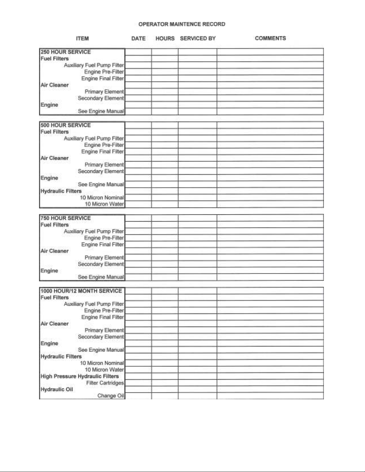
CHECK ALL
CHECK ALL FLUID LEVELS, GREASE &
VISUALLY INSPECT CRUSHER DAILY
Page 52
780 West Park Ave NW
Huron, South Dakota 57350
www.overbuilt.com
6469
0881
Web:
E-mail: sal
Phone: (605) 352-
Fax: (605) 352-
 Loading...