

Page 1
2004 Oventrop 1
Technical information
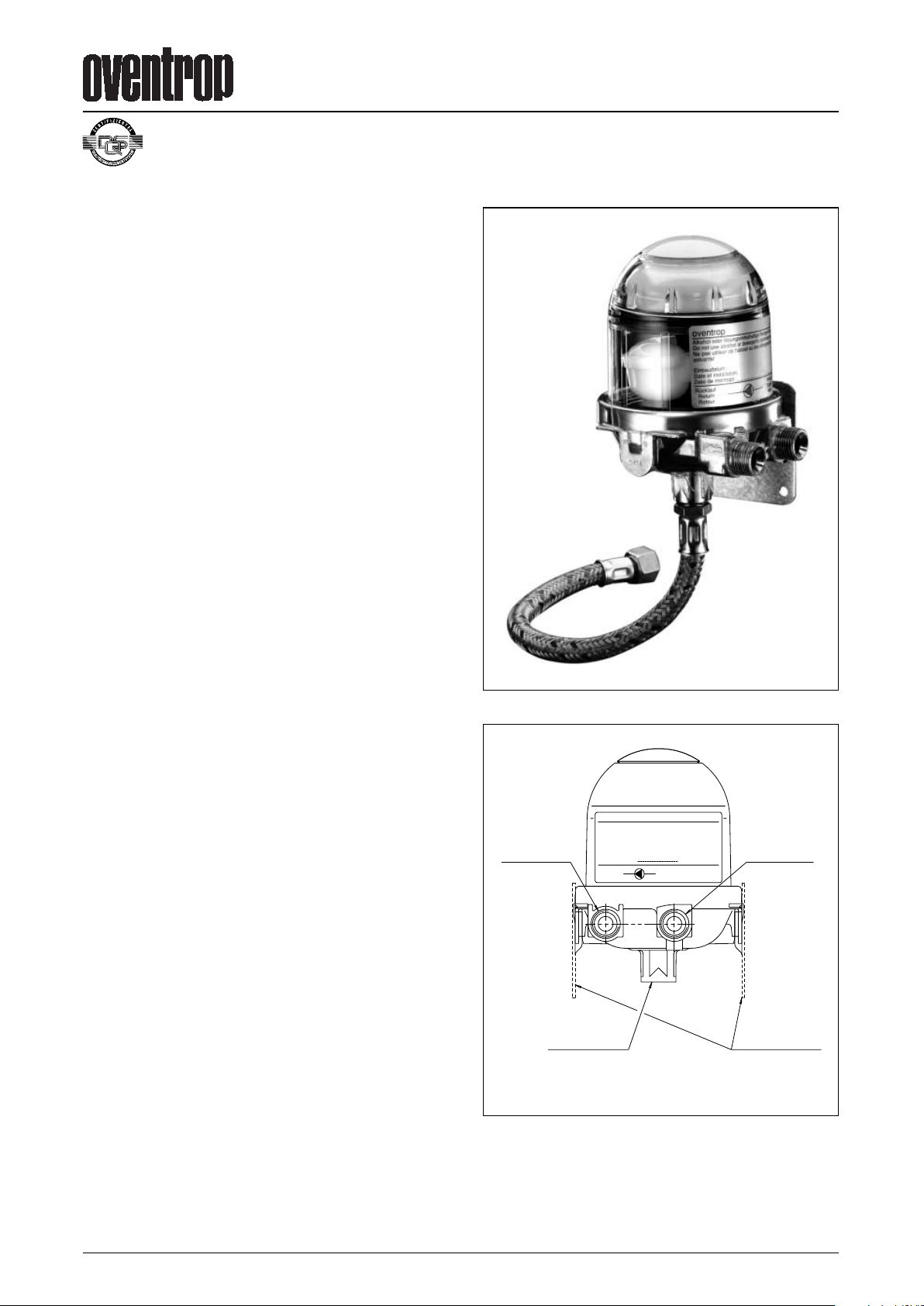
Heating oil deaerator
“Toc-Uno-N”
The Oventrop Quality Management
System is certified to DIN-EN-ISO 9001
View burner side:
oventrop
Toc-Uno-N“
Alkohol oder lösungsmittelhaltige Reiniger nicht benutzen!
Do not use alcool or detergents containing solvents!
Ne pas utiliser de l'alcool ou des détergents contentant
des solvants!
Einbaudatum:
Date of installation:
Date de montage:
F.W. OVENTROP
GmbH & Co. KG
Paul-Oventrop-Str. 1
D-59939 Olsberg
Rücklauf
Return
Retour
Vorlauf
Supply
Aller
Typ: 214 29
TÜV geprüft
Return
from
burner
Supply
to
burner
Fixing plate
right or left
From tank
Tender specification:
Oventrop heating oil deaerator “Toc-Uno-N” for use in one
pipe systems with return flow feed (suction system) for automatic dearation of heating oil. Body of deaerator made of
metal, with wall bracket. Float case made of transparent
plastic for function control. Connection for suction pipe to the
tank
1
⁄4” female thread. Connection to burner 1⁄4” female thread
or
3
⁄8” male thread with inner taper for hose connection.
Item no. 214 29 51
Inlet port (tank side)
1
⁄4” female thread
Outlet port (burner side)
3
⁄8” male thread with inner taper for
hose connection
Accessories: Flexible hose 300 mm, one port
1
⁄4” male thread,
one port with collar nut
3
⁄8” with seal for the connection to a
heating oil filter with male thread
3
⁄8” on burner side
Item no. 214 29 01
Inlet and outlet port
1
⁄4” female thread without accessories
Application:
Oventrop heating oil deaerator for use in heating oil
installations (suction systems) which are operated as one pipe
systems with return flow feed. A heating oil filter with isolation
has to be installed in front of the “Toc-Uno-N”. A return pipe
back to the tank is no longer required. The “Toc-Uno-N”
automatically deaerates the heating oil in heating oil
installations.
Technical data:
Connections
Tank side:
1
⁄4” female thread
Burner side:
3
⁄8” male thread with taper for
burner hoses or
1
⁄4” female thread
Fluid: Heating oil type EL according to
DIN 51603-1 (09.2003)
Max. nozzle capacity: 110 l/h
Max. return flow of
heating oil: 120 l/h
Dearation capacity: min. of 6 l/h air or gas emissions
Installation position: vertical, deaerator cap pointing
upwards
Max. ambient temperature: 60°C*
Max. working temperature: 60°C*
Max. working pressure: 0.7 bar corresponding to a static
column of oil of 8 m for tanks
located at a higher level
Max. suction pressure: -0.5 bar
Max. test pressure: 6 bar
Dimensions [mm]: 107 x 97 x 133
(L x D x H) with female thread:
95 x 97 x 133
TÜV tested: TÜV Rhineland, No.: S137 2004 T1
* According to DIN 4755, the max. admissible temperature of
heating oil in heating oil installations is 40°C
Page 2
2 2004 Oventrop
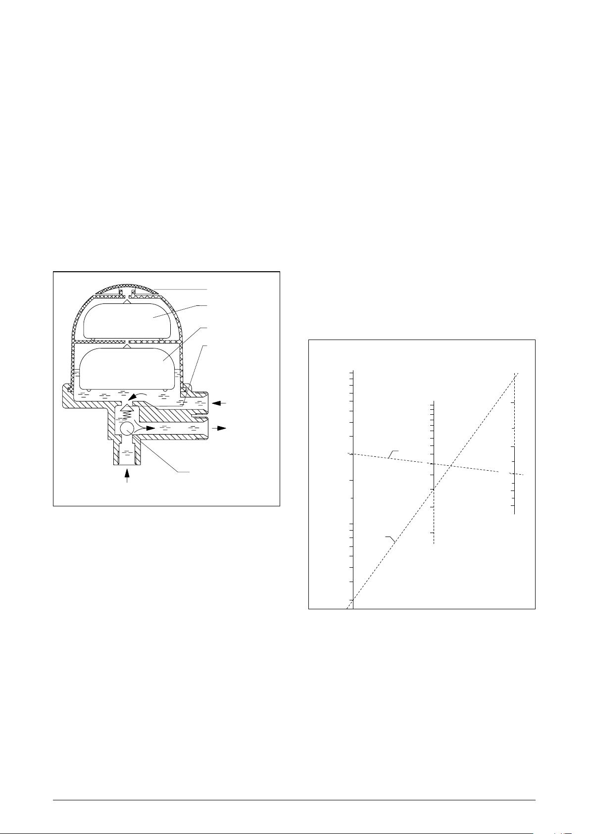
Function:
Oventrop heating oil deaerator “Toc-Uno-N” for automatic
deaeration of heating oil.
The burner pump draws oil through the suction pipe via the
filter mounted in front of the deaerator, the connection pipe
and the check valve. Normally, a small portion of oil is
pumped to the nozzle by the burner pump and is burnt
(per 10 kW of heat output about 1 litre of oil per hour). The
excess is fed into the deaerator via the return pipe. Air and
gas emissions rise and are expelled into the atmosphere via
the float valve. The deaerated oil is fed into the supply via a
diaphragm controlled valve. As a result, only the used
quantity is drawn from the tank via the suction pipe and the
filter. At the same time, the working temperature of the oil
pump is used for pre-warming the oil.
Under working conditions, a relatively constant filling height
will be present in the lower part of the float case. Depending
on the working conditions, this part may even fill up
completely.
If heating oil enters the upper part with the security float, the
deaerator has to be replaced.
The supply and return connection must not be mixed up as
this may cause damage to the deaerator and the burner
pump.
Pressure test:
When carrying out the pressure test of the suction pipe, the
pressure test device must not be connected to the “Toc-UnoN” as the integrated check valve will prevent the pressure
transmission on the tank side.
Moreover, the float valves of a new unfilled “Toc-Uno-N” are
opened so that it should not be included in the pressure test.
Notes:
Do not use detergents containing alcohol or solvents as
these may damage the plastic parts.
Sizing of the suction pipe:
The suction pipe towards the tank should be sized in such a
way that the velocity of the heating oil during burner operation
is between 0.2 and 0.5 m/s (DIN 4755). If the suction pipes are
oversized, velocity is reduced in such a way that the gas
emissions are not transported constantly and gather as big air
bubbles in upper pipe sections. If a big air bubble reaches the
burner, it may cause a malfunction.
For small burner units in one or two family houses, the inner
pipe dimension of 4 mm (e.g. pipe 6 x 1) is often sufficient.
Apart from the velocity, the flow resistance and the suction
height have to be taken into consideration.
b
a
min. min.
3
2
3
4
0.1
0.5
0.4
0.3
0.2
15
10
9
8
7
6
5
4
80
70
60
50
40
30
20
10
9
8
7
6
5
*
90
100
110
12
Examples:
a. For a pump capacity of 30 l/h (about 300 kW), with a
medium suction speed of 0.3 m/s, a pipe of 8 x 1 mm with
an inner diameter of 6 mm is required.
b. A small installation with a heat output of 30 kW,
corresponding to a flow rate of 3 l/h, is equipped with a
pipe of 6 x 1 with an inner diameter of 4 mm. The velocity
is very low then (about 0.07 m/s), but possible airlocks are
very small and do not cause malfunctions.
Installation:
The heating oil deaerator is to be installed at a suitable
location with the help of the enclosed fixing plate. To mount
the latter on the burner wall by use of the enclosed sheet
metal screws, provide 3 mm tapping points. Care should be
taken that the max. ambient temperature does not exceed
60°C, i.e. not mount the “Toc-Uno-N” near an un-insulated
part of the boiler or the exhaust pipe or above flaps of the
heating which can be opened.
The heating oil deaerator is to be installed vertically.
It can be installed above and below the oil level.
For function control, the “Toc-Uno-N” should be installed at a
location which is well visible and easily accessible.
When converting from two pipe systems to one pipe
operation, the pipe dimension has to be reduced if required,
see “Sizing of the suction pipe”.
If constructional conditions allow, the pipe should be installed
in such a way that it acts as a “self-monitoring suction pipe”
according to TRbF 50. It should then be installed with an even
decline towards the tank and all check valves in front of the
“Toc-Uno-N” have to be removed. If a leakage occurs, the
column of liquid in the declining pipe breaks off.
Functional scheme:
Oil capacity
in l/h
Inner pipe
diameter
in mm
Oil velocity
in m/s
Velocity of the heating oil in suction pipes
during operation according to DIN 4755:
0,2 bis 0,5 m/s
* Avoid dimensions of less than 4 mm
Nomogram:
Return
Security float
Float
Differential
pressure
relief valve
Cap
Supply
from
tank
Non-return ball
check valve
Page 3
2004 Oventrop 3
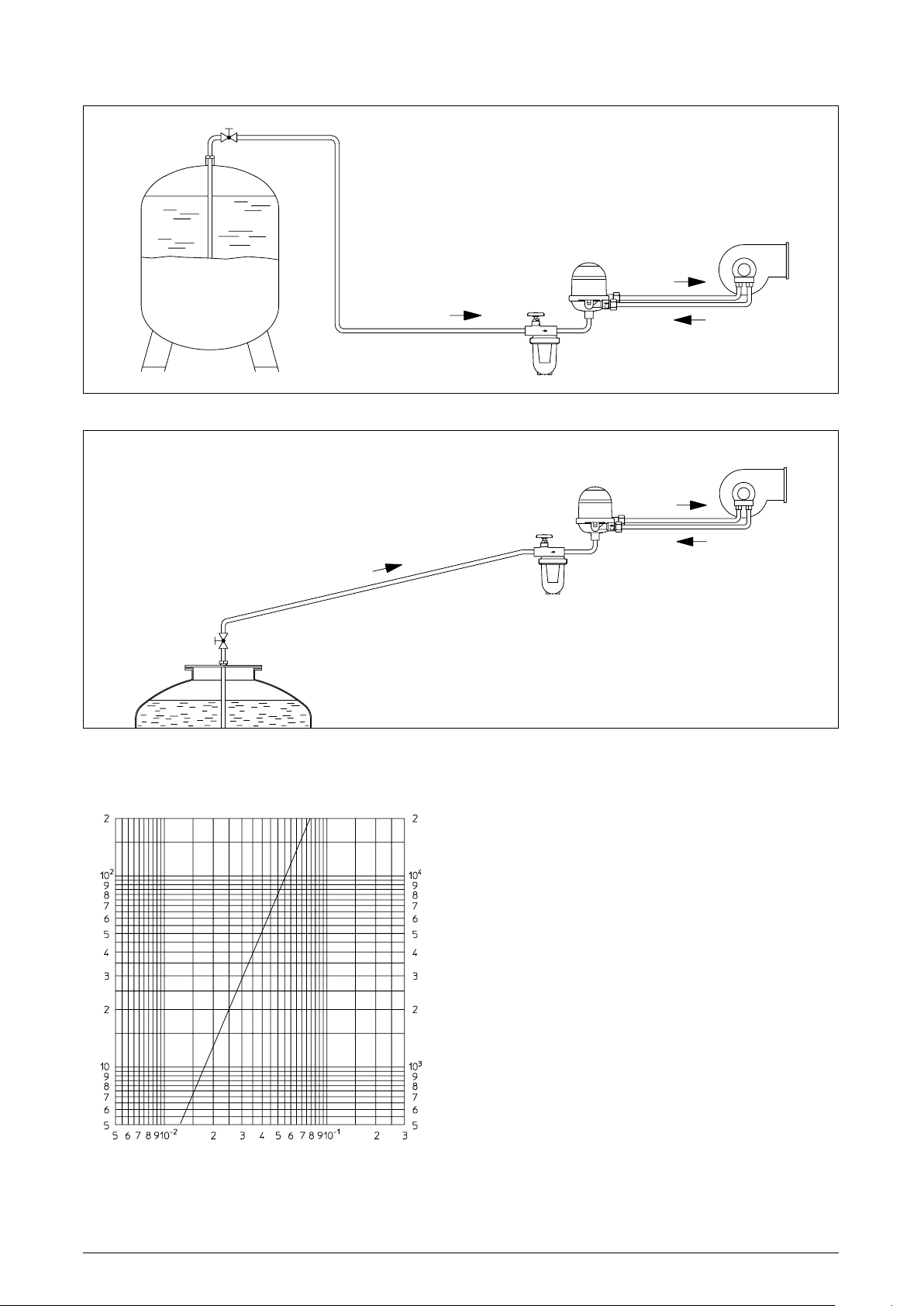
Exemples of installation:
Installation of the heating oil deaerator below the oil level, e.g. battery tank
Installation of the heating oil deaerator above the oil level, e.g. underground tank
Battery tank
“Oilpur”
“Oilpur”
“Toc-Uno-N”
Burner
Underground
tank
“Toc-Uno-N”
Burner
Formation of oil froth and possible malfunctions:
Oil froth may develop if large quantities of air are delivered
via the burner pump together with the heating oil. These may
lead to malfunctions of the burner.
Possible reasons are:
– leakage in the suction pipe
(sealing, re-tighten fittings)
– initial operation of the suction pipe
(if required, fill pipe before)
– oversized suction pipe
(install smaller pipe,
see “Sizing of suction pipe”)
Durchflussdiagramm:
Pressure loss of the suction system
Pressure loss ∆p [mbar]
Pressure loss ∆p [Pascal]
·
Flow rate V [l/s]
Page 4
4 2004 Oventrop
Accessories:
The deaerator expels gas emissions into the atmosphere
which may lead to smell nuisances in badly ventilated boilerrooms. In this case, a hose may be pushed onto a hose nipple
and the air may be expelled. Please ensure that the hose is
not obturated.
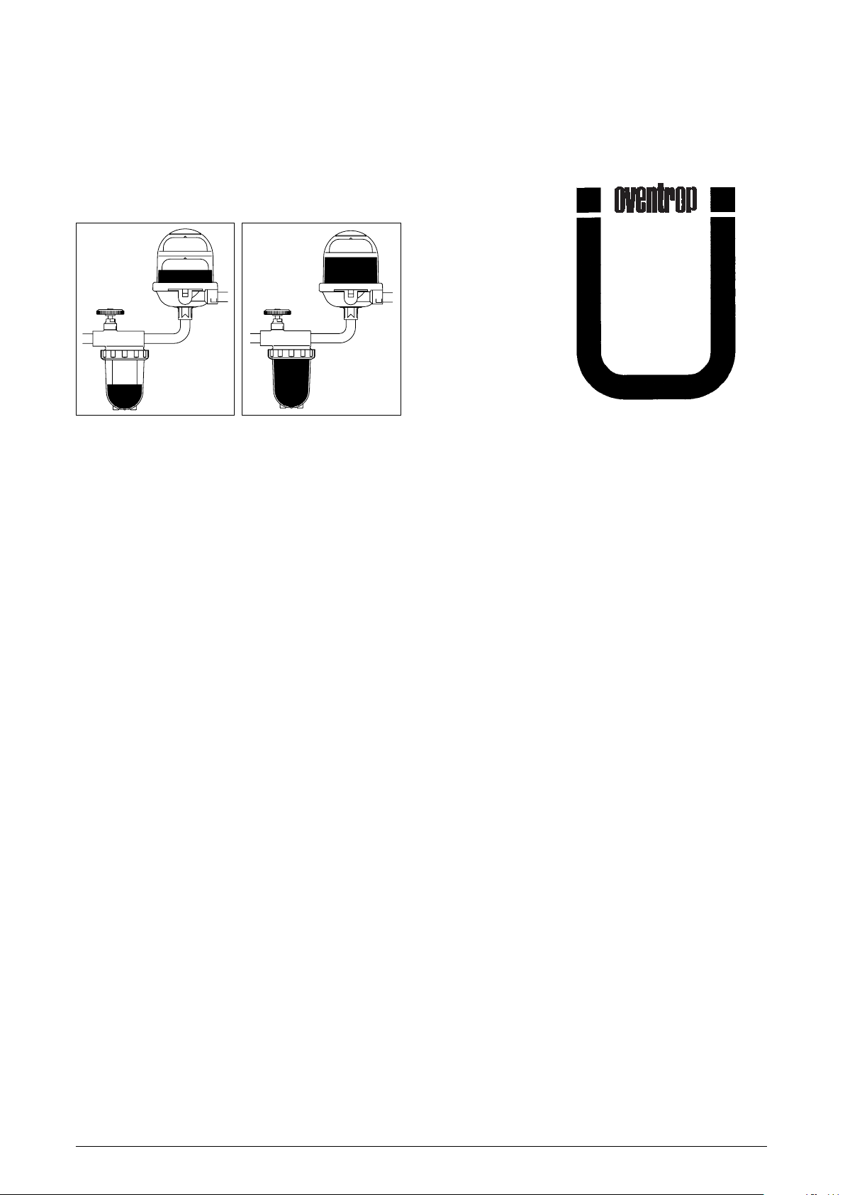
Air pockets in the filter cup of the heating oil filter installed in front of the heating oil deaerator:
The heating oil is filtered before deaeration and during this
process it is possible that some of the air in the oil is retained
by the oil moistened filter insert so that an air pocket forms in
the filter cup.
This is especially noticeable where a large portion of air is in
the oil. During burner operation, this air cushion is the cause
for a sinking oil level in the filter cup when an underlying
pressure is built up. However, as the inside of the filter insert
is completely filled with oil, the installation continues its
operation.
Filling height in the float case:
Depending on the working conditions, different filling heights
may develop in the lower float case.
This chamber may also be filled completely, e.g. if no gas
emissions exist in case of a tank located at a higher level. The
existing air may then dissolve in the heating oil in the circuit
between the burner pump and the chamber of the deaerator.
If working conditions change, e.g. by a sinking oil level in the
tank, a new air cushion may grow.
In case of heating oil in the upper part of the security float, the
deaerator has to be replaced.
Parallel installation of several “Toc-Uno-N”:
If higher nozzle capacities than 110 l/h are required, it is
possible to install two or more deaerators in parallel. It must
be ensured that the maximum return flow does not exceed
120 l/h per installed deaerator. The return flow is the pump
output minus the volume of burnt oil.
Pressure operation:
The “Toc-Duo-N” must not be used under pressure, i.e.
behind a feed pump in the supply pipe. This is not sensible as
air is only emitted in suction operated systems.
According to DIN 4755 it must be ensured that in closed pipe
sections a rise in pressure due to an increase in temperature
of the heating oil must be balanced off (e.g. by installing a
pressure compensation device). Alternatively, closed pipe
sections can be avoided by renouncing check valves.
Increased pressure can lead to damage of the heating oil
deaerator or other installed equipment.
Flooding:
The Oventrop heating oil deaerator “Toc-Uno-N” may also be
installed in areas prone to flooding with the height of flooding
not exceeding 5 m.
As dirt may block the vent bores which may lead to
malfunctions, a replacement of the “Toc-Uno-N” is
recommended after a flooding.
Tested by TÜV Rhineland
DIN
4736-2
Subject to technical modification without notice.
Product range 8 Printed on paper free from
ti 158-1/10/2004/MW chlorine bleaching.
F. W. OVENTROP GmbH & Co. KG
Paul-Oventrop-Straße 1
D-59939 Olsberg
Telefon (029 62) 82 -0
Te lefax (029 62) 82 -450
Internet http://www.oventrop.de
eMail [email protected]
OVENTROP UK LTD.
Unit I – The Loddon Centre
Wade Road
Basingstoke, Hampshire RG24 8FL
Telephone (012 56) 33 0441
Telefax (Sales) (012 56) 330525
Telefax (General) (01256) 47 09 70
E-Mail [email protected]
 Loading...