

Page 1
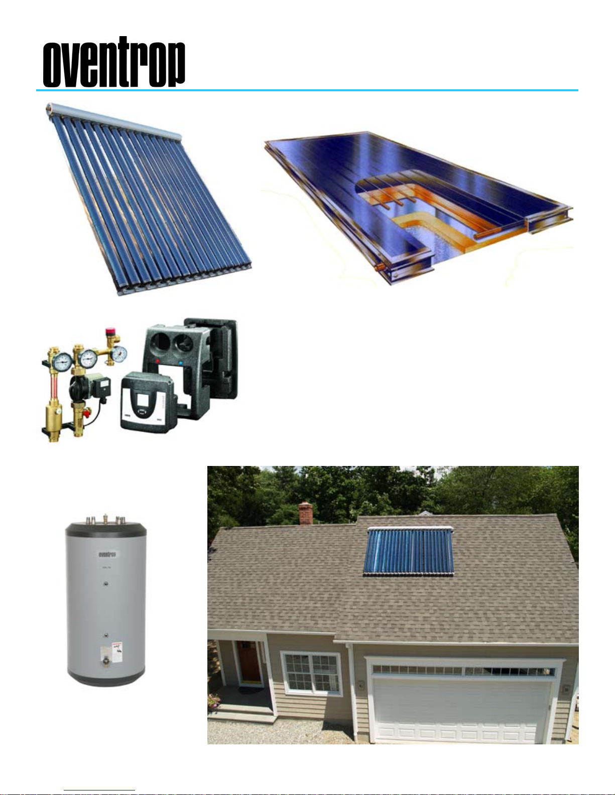
OVSOL
Solar System Manual
Solar hot water system installation guide
for flat plate and evacuated tube systems.
Page 2

table of contents
System Components. . . . . . . . . . . . . . . . . . . . . . . . . . . . . . . . . . . . . . . . . . . . . . . . . . . . . . . 2
Introduction. . . . . . . . . . . . . . . . . . . . . . . . . . . . . . . . . . . . . . . . . . . . . . . . . . . . . . . . . . . . . . 3
Section One:
General Guidelines and Precautions. . . . . . . . . . . . . . . . . . . . . . . . . . . . . . . . . . . . . . . . . . . 4
Section Two:
Solar thermal system design guidelines . . . . . . . . . . . . . . . . . . . . . . . . . . . . . . . . . . . . . . . 5
Section Three:
Collector Layout Orientation and Siting. . . . . . . . . . . . . . . . . . . . . . . . . . . . . . . . . . . . . . . . 9
Section Four:
Evacuated tube Collector Dimensions and Technical Data. . . . . . . . . . . . . . . . . . . . . . . . . . 11
Evacuated tube collector shipping contents . . . . . . . . . . . . . . . . . . . . . . . . . . . . . . . . . . . . 12
Evacuated tube collector mounting systems and shipping contents . . . . . . . .. . . . . . . . . . . 13
Section Five:
Flush Roof Mounting
Flush Mounting on Asphalt Shingles. . . . . . . . . . . . . . . . . . . . . . . . . . . . . . . . . . . . . . . . . . . 16
Flush Mounting on Tile Roofs. . .. . . . . . . . . . . . . . . . . . . . . . . . . . . . . . . . . . . . . . . . . . . . . 18
Flush Mounting on Metal Seamed Roofs. . . . . . . . . . . . . . . . . . . . . . . . . . . . . . . . . . . . . . . 19
Multiple Collector Arrays . . . . . .. . . . . . . . . . . . . . . . . . . . . . . . . . . . . . . . . . . . . . . . . . . . . 21
Piping the collector . . . . . . . . . . . . . . . . . . . . . . . . . . . . . . . . . . . . . . . . . . . . . . . . . . . . . . . 23
Section Six:
Adjustable Angle Roof Mounting Assembly for rack mounting kits 540 00 28-16, -8 . . . . . . 24
Piping the collector . . . . . . . . . . . . . . . . . . . . . . . . . . . . . . . . . . . . . . . . . . . . . . . . . . . . . . . 33
Section Seven:
Flat Plate collector installation
Flat Plate collector Dimensions and Technical Data. . . . . . . . . . . . . . . . . . . . . . . . . . . . . . . 34
Flat Plate collector mounting systems and shipping contents . . . . . . . . . . .. . . . . . . . . . . 35
Flat Plate collector tilt mounted nstallation instructions . . . . . . . . . . . . . . . . . . . . . . . . . . . . . . 38
Flat Plate collector ush mounted installation instructions. . . . . . . . . . . . . . . . . . . . . . . . . . . . . 42
Flat Plate collector strut mounted installation instructions. . . . . . . . . . . . . . . . . . . . . . . . . . . . . 44
Section Eight:
System Piping
System Piping Diagrams . . . . . . . . . . . . . . . . . . . . . . . . . . . . . . . . . . . . . . . . . . . . . . . . . . . . . . .45
Piping single tanks systems . . . . . . . . . . . . . . . . . . . . . . . . . . . . . . . . . . . . . . . . . . . . . . . . . . 62
Piping two tanks systems. . . . . . . . . . . . . . . . . . . . . . . . . . . . . . . . . . . . . . . . . . . . . . . . . . . . . . 63
Section Nine:
Component Installation
Tank dimensions and capacities . . . . . . . . . . . . . . . . . . . . . . . . . . . . . . . . . . . . . . . . . . . . . . . . .64
Regusol pumping station installation . . . . . . . . . . . . . . . . . . . . . . . . . . . . . . . . . . . . . . . . . . . 66
Controller Installation and Operation. . . . . . . . . . . . . . . . . . . . . . . . . . . . . . . . . . . . . . . . . . . . . 68
Section Ten:
System Commissioning and Operation
Fill, Flush, and Check. . . . . . . . . . . . . . . . . . . . . . . . . . . . . . . . . . . . . . . . . . . . . . . . . . . . . . . . . .71
Commissioning / Operation . . . . . . . . . . . . . . . . . . . . . . . . . . . . . . . . . . . . . . . . . . . . . . . . . . 72
Section Eleven:
System Troubleshooting. . . . . . . . . . . . . . . . . . . . . . . . . . . . . . . . . . . . . . . . . . . . . . . . . . . . . . . 73
Section Twelve:
Oventrop Warranty . . . . .. . . . . . . . . . . . . . . . . . . . . . . . . . . . . . . . . . . . . . . . . . . . . . . . . . . . . . 76
082809
1
Page 3
system components
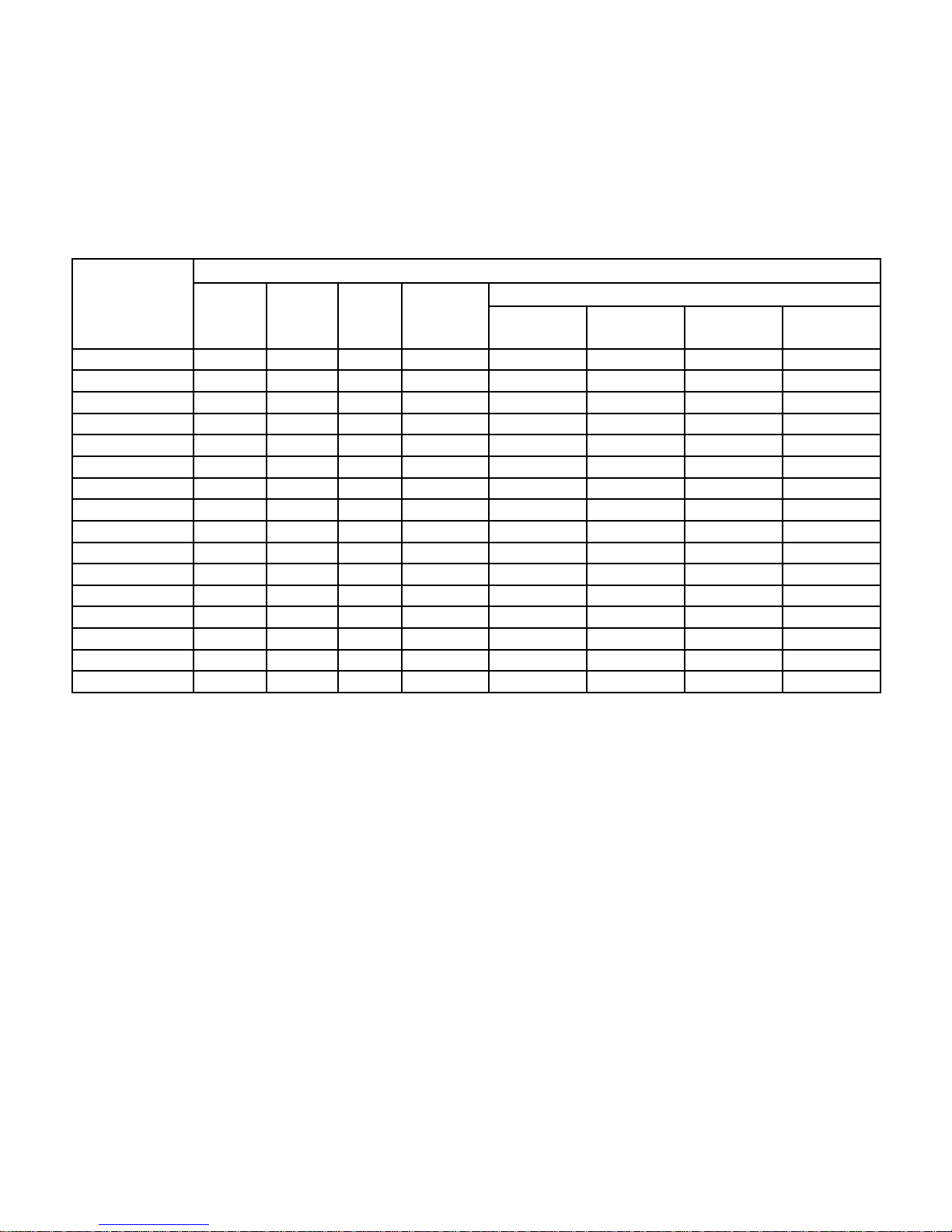
The OVSOL System for solar energy described in this manual, when properly installed
and maintained, meets the minimum standards established by the SRCC.
This certication does not imply endorsement or warranty of this product by the SRCC.
System Contents
System Model
OVSOL 5-16-SC - 1 - 1 80 gallon - - -
OVSOL 5-16-SCE - 1 - 1 - 80 gallon - -
OVSOL 5-16-DC - 1 - 1 - - 80 gallon -
OVSOL 5-16-DCE - 1 - 1 - - - 80 gallon
OVSOL 5-24-SC - 1 1 1 119 gallon - - -
OVSOL 5-24-SCE - 1 1 1 - 119 gallon - -
OVSOL 5-24-DC - 1 1 1 - - 119 gallon -
OVSOL 5-24-DCE - 1 1 1 - - - 119 gallon
OVSOL FP-2-SC 2 - - 1 80 gallon - - -
OVSOL FP-2-SCE 2 - - 1 - 80 gallon - -
OVSOL FP-2-DC 2 - - 1 - - 80 gallon -
OVSOL FP-2-DCE 2 - - 1 - - - 80 gallon
OVSOL FP-3-SC 3 - - 1 119 gallon - - -
OVSOL FP-3-SCE 3 - - 1 - 119 gallon - -
OVSOL FP-3-DC 3 - - 1 - - 119 gallon -
OVSOL FP-3-DCE 3 - - 1 - - - 119 gallon
OVF-32 OV 5-16 OV 5-8
Regusol
EL 130
SIngle Coil
Tank Capacity and Type
Single Coil
Electric
Dual Coil
Dual Coil
Electric
OVF-32 - Oventrop 4’ x 8’ at plate collector
OV 5-16 - Oventrop evacuated tube collector with 16 tubes
OV 5-8 - Oventrop evacuated tube collector with 8 tubes
2
082809
Page 4

introduction
OVSOL System
This manual provides installation instructions for OVSOL System for solar domestic hot water heating. The
OVSOL solar energy system described in this manual, when properly installed and maintained, meets the
minimum standards established by the SRCC.
This certication does not imply endorsement or warranty of this product by the SRCC.
Planning before the installation and use of the solar collector array should include:
l Solar hot water system design.
l Properly sized solar storage tank.
l Properly sized and insulated solar loop (plumbing circuit).
l An air bleed valve at the highest point in the collector circuit located for convenient access.
l Roof penetrations for piping to and from the collector.
l System components for closed loop solar systems—tank, heat exchanger, solar loop circulator,
pressure relief valve, solar controller, expansion tank, ll and drain valves, pressure and temperature
gauges.
l Propylene glycol (antifreeze) to provide protection from frost and high idle mode temperatures of
375 °F.
Requirements for each installation should be fully detailed by a system schematic and specications.
The assembly and installation instructions described in this manual have been carefully prepared. It is very
important to read these instructions thoroughly before proceeding with the collector installation. An effort has
been made to conform procedures in this manual to the specications of various governmental and agency solar
programs. Also, many programs allow substitution of manufacturers’ standards for program standards. If this
is the case, the enclosed manual can be used to comply with program standards. Cases where it is unclear
whether the enclosed manufacturers’ standards can be substituted for program standards should be brought to
the attention of the particular program administrator or to Oventrop Corporation for clarication.
Be certain to follow all applicable building and safety codes for installations of solar thermal collectors.
Compliance with local codes is essential. Local code requirements must be met for penetrating structural
members and re-rated assemblies. Collectors and piping must be installed in such a way that the performance
of any structural member or re-rated assembly is not reduced. Be especially aware of safety regulations when
working upon rooftops. It is the buyer’s responsibility to secure all permits and approvals before purchasing and
attempting the installation of this equipment.
Specications are subject to change without notice.
Installing Contractor
Company________________________________________
Installer’s name___________________________________
Address_________________________________________
City, State, Zip____________________________________
Phone Number____________________________________
082809
3
Page 5

section one
Guidelines and Precautions
Installing Collector Arrays
It is not recommended to install more than three 16-tube collectors in a series (64 tubes). Larger
installations will require parallel piping for balanced ow through each array. Balancing valves should
be installed on multiple arrays. One roof mounting kit is needed for each single collector module. Each
additional collector will require an expansion kit.
Closed Loop and Drainback
OVSOL collectors can be installed for both closed loop and drainback solar heating applications.
Freeze Tolerance Limits
Freeze tolerance limits are based upon the freeze and burst protection of the antifreeze used in the solar
closed loop, or the mixture of the glycol-to-water ratio. Oventrop NT-40 is a 40% glycol-to-water mix with
freeze protection to -6o F and burst protection to -60o F. Oventrop NT-50 is a 50% glycol-to-water mix with
freeze protection to -30o F and burst protection to -60o F. For additional protection, the Regusol 130 EL
control has an antifreeze function (“OCF”) that can be programmed to enable the circulator to protect the
antifreeze from freezing or thickening.
Shedding Snow
In regions of snow accumulation, evacuated tube collector tilt angles above 50° will shed snow from collectors even after severe storms. Therefore, in heavy snow areas, it is critical that collectors be sloped to
at least a 50° tilt angle. If collectors are installed on a at roof in an area that receives heavy snowfall, the
lower end of the units should be at least 18” above the roof level to minimize chances of snow build-up on
the bottom of the collectors.
Transport of Collector
The collector should be transported to the roof in parts and then assembled together on the rooftop.
Lightning Protection
In areas of high incidence of lightning, one lightning rod should be considered. If there is a ready-made
lightning protection device, please connect it with the collector.
Minimum Inclination Angle of Collector (for Evacuated tube collectors only)
In order to ensure heat pipe delivery, a minimum inclination angle of 25° is necessary for OV SOL-5 collectors. If the tilt angle of the roof is not above 25°, please build necessary roof mounting racks.
Precautions
Temperatures in excess of 390 °F are possible in the condenser (top metal protruding bulb) when exposed
to bright sunlight or diffused insolation. DO NOT TOUCH the condenser. Store the tubes in a safe location,
away from the sun, during the installation of the roof mounting rack. Tubes are installed as the last step.
Oventrop Corporation will not be liable for burns or personal injury due to the touching of a hot condenser.
Handle the tubes with care to avoid accidental bending of the heat pipe at the condenser which may cause
damage to the heat pipe or the vacuum seal.
The maximum solar loop operating pressure is 87 psi. The pressure relief valve must be set to open below
87 psi. A 75 psi pressure relief valve is suggested. Normal operating pressures for a solar closed loop are
25 to 35 psi.
4
082809
Page 6
section two
Solar thermal system design guidelines
Solar hot water systems are simple in principal but complicated in practice. This guide is designed to
describe and explain the process for designing a solar hot water system. There are many ways to
design a solar hot water system to achieve the same end result. The two system types that Oventrop
uses are external heat exchanger systems (i.e. the Regusol X) and Immersed coil heat exchangers (i.e.
internal coil tanks). All of Oventrop’s systems are based on one of these two variants.
Solar Design Basics
Incoming solar radiation at the earth’s surface on a perfectly clear day is approximately 300 BTU/H
per square foot. With that said, solar collector performance depends on several factors. These
factors include, but are not limited to: ambient temperature at the location of the solar collector,
required operating temperature of the working uid in the collector, incoming solar radiation
(energy), geographical location of the collector, shading of the collector, and inclination angle of the
collector.
The difference in temperature between the working uid and the ambient temperature drives the heat
loss of the solar collector. This temperature difference has the greatest inuence on the solar
collector’s thermal efciency. This efciency measures the solar collector’s ability to convert
incoming solar radiation to usable heat in the form of a hot working uid. This hot working uid can
be used for any application.
The availability of solar radiation (energy) is dependent on weather, time of year, site shading, and
collector inclination angle. Throughout the year, the distance of the sun from the horizon will
change from the longest on the rst day of summer to the shortest on the rst day of winter. This
translates to a 47-degree change in the sun’s angle with respect to the collector throughout the year.
The optimal inclination angle to minimize this change and maximize year-round performance is
equivalent to the latitude at which the collector is located. Shading at the collector site determines
the amount of available solar radiation to which the collector is exposed.
Understanding that all of the above factors affect the performance of the solar thermal collector,
one cannot make a location independent generalization of collector performance.
Design conditions are calculated as the maximum instantaneous solar radiation, in other words, the
most energy the system can handle at any given time. For design conditions we assume the collector
is at an operating efciency of 75%, on a clear day, facing south, with no shading. Due to this efciency the
maximum output of the solar collector at design is rated at 225 BTU/H per square foot. This value is in no
way a guarantee or estimate of any Oventrop collector’s performance. The table below shows the design
BTU/H
rating of each Oventrop solar collector.
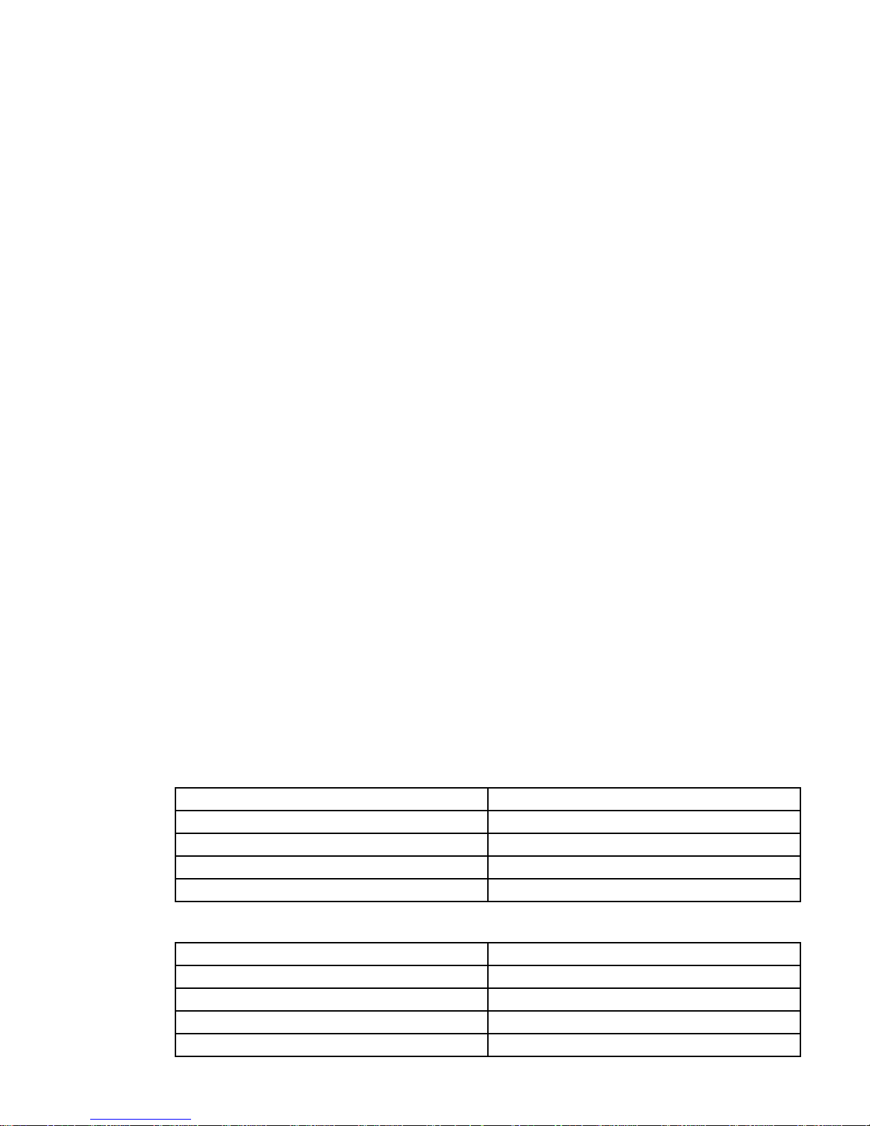
Collector Type Design Conditions BTU/H rating
OV 5-16 Evacuated tube collector 6,277 BTU/H
OVF-21 Flat plate collector 4,230 BTU/H
OVF-32 Flat plate collector 6,615 BTU/H
OVF-40 Flat plate collector 8,280 BTU/H
Table 2, below, shows the design ow rates for each Oventrop collector type.
Collector Type Design Flow Rate per collector
OV 5-16 Evacuated tube collector 0.75 GPM
OVF-21 Flat plate collector 0.525 GPM
OVF-32 Flat plate collector 0.80 GPM
OVF-40 Flat plate collector 1.0 GPM
082809
5
Page 7

These ow rates were chosen based on the collection area of each solar collector and the incoming solar
radiation at design conditions. The ow rates allow the collectors to achieve an 18 degree Fahrenheit temperature
rise across the solar loop.
‘The sun is the source, the system is the battery.’
Solar energy is only available for a limited time during each day. It is because of this that the energy must be
captured and stored for later use. The amount of energy stored is related to the system operating temperature
(i.e. radiant oor heat at 100F or fan coil units at 180F), the storage volume, and to the maximum temperature in
the storage vessel. Maximum energy storage [BTU’s] is calculated using equation 1, below.
Maximum Stored Energy = 8.33 x Storage volume [Gal] x (Max. tank temp. – System operating temp.)
Where, Storage volume is in gallons and all temperatures are in Fahrenheit. Optimization of this equation has
determined the design number of gallons per collector. The table below shows the number of gallons of storage
recommended per collector.
Collector Type Gallons of Storage per Collector
OV 5-16 Evacuated tube collector 66 Gallons
OVF-21 Flat plate collector 27 Gallons
OVF-32 Flat plate collector 41 Gallons
OVF-40 Flat plate collector 53 Gallons
These storage values are calculated for a national average. Since daily solar radiation varies signicantly from the
South to the North, these storage values are not required, only recommended. Less storage can be used in the
northern latitudes and more storage can be used in the southern latitudes. The storage values should only vary plus
or minus 5% from the recommended values listed above.
Another way to think of solar storage is as the fuel tank of the system. It is used to store energy that can be used
over the entire day. In this way the daily load is matched to the daily collector output. Oventrop solar hot water
systems are designed to optimize the transfer of energy from the collectors to the solar storage vessel.
Small systems
Internal coil tanks are used for Oventrop smaller systems. This allows for the ease of installation for system
packages. Oventrop has pre-packaged solar domestic hot water systems for daily loads of 80 and 115 gallons.
Depending on location these packaged systems will provide between 30 and 70 percent of the annual domestic hot
water load.
Using a similar conguration as the pre-packaged systems, larger domestic hot water loads can be accommodated.
Variations of small systems are sized by tank size and can be arranged for up to 160 gallons and 230 gallons of daily
usage. These small systems are comfortably in the design range of the Regusol EL 130 solar pumping station. This
pumping station is designed for a maximum ow rate of four (4) gallons per minute. Because the Regusol EL 130 is
constructed in ¾”, the maximum ow rate is based on the maximum trouble free ow through ¾” pipe.
Medium systems
Medium systems are above the ow range established for the Regusol EL 130 and have increasingly larger storage
requirements. It is for these reasons that the Regusol-X pumping station with heat exchanger was developed.
External heat exchangers provide exibility of design and reduce cost when considering larger storage volume and
collector arrays. The Regusol-X is designed to be used with any storage vessel that is built for hot water storage; it
does not require internal heat exchangers.
6
082809
Page 8
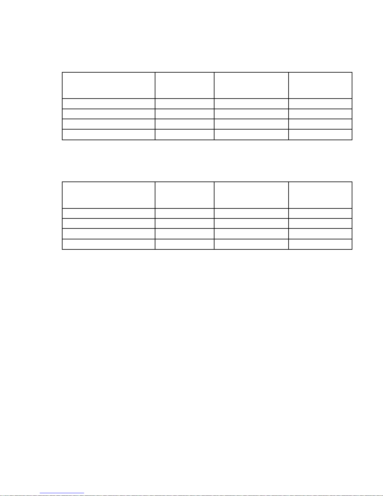
The design limits for the Regusol-X are based on the pressure drop through the heat exchanger, the pump capacity,
and the maximum output of the heat exchanger. The table below lists the maximum number of collectors allowed to
be used with each Regusol-X.
For Single Speed Pumps
Maximum number
Collector Type
OV 5-16 Evacuated tube collector 3 6 8
OVF-21 Flat plate collector 7 9 12
OVF-32 Flat plate collector
OVF-40 Flat plate collector
Using an external heat exchanger allows for either multiple or single tank congurations. As long as the storage is
sized correctly the tanks can be in any conguration.
For Three Speed Pumps
Collector Type
OV 5-16 Evacuated tube collector 4 7 8
OVF-21 Flat plate collector 7 10 12
OVF-32 Flat plate collector
OVF-40 Flat plate collector
of collectors on one
Regusol EL130*
5
4
Maximum number
of collectors on one
Regusol EL130*
5
4
Maximum number
of collectors on one
Regusol-X 15**
6 8
5 6
Maximum number
of collectors on one
Regusol-X 15**
6 8
5 6
Maximum number
of collectors on one
Regusol-X 25**
Maximum number
of collectors on one
Regusol-X 25**
* No more than three (3) OV 5-16 tube collectors are to be piped in series through the Regusol EL130 without a
booster pump.
** No more than two (2) OV 5-16 tube collectors are to be piped in series through the Regusol X without a booster
pump.
082809
7
Page 9
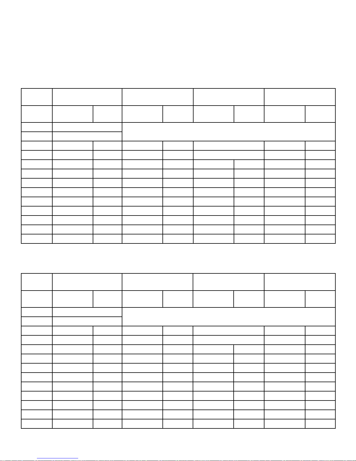
Oventrop Solar Systems Sizing Chart
The following solar sizing charts shows various combinations of solar collector quantities to Regusol pumping stations an the
design solar storage volume.
Tank selections are up to the designer for Regusol X systems and larger.
For Single Speed Pumps
Collector
Type
Number of
collectors
1 OVSOL 5-16 package
1.5 OVSOL 5-24 package
2 Regusol EL130 160 Regusol EL130 54 OVSOL FP-2 package Regusol EL130 106
3 Regusol EL130 230 Regusol EL130 81 OVSOL FP-3 package Regusol EL130 159
4 Regusol X-15 264 Regusol EL130 108 Regusol EL130 160 Regusol EL130 212
5 Regusol X-15 330 Regusol EL130 135 Regusol EL130 205 Regusol X-15 265
6 Regusol X-15 396 Regusol EL130 162 Regusol X-15 246 Regusol X-25 318
7 Regusol X-15 462 Regusol EL130 189 Regusol X-25 287
8 Regusol X-25 528 Regusol X-15 216 Regusol X-25 328
9 Regusol X-15 243
10 Regusol X-25 270
11 Regusol X-25 297
12 Regusol X-25 324
OV 5-16 Evacuated tube
collector
Pumping
Station
Storage in
Gallons
OVF-21 Flat plate collector OVF-32 Flat plate collector OVF-40 Flat plate collector
Pumping
Station
Storage in
Gallons
Pumping
Station
N/A
Storage in
Gallons
Pumping
Station
Storage in
Gallons
For Three Speed Pumps
Collector
Type
Number of
collectors
1 OVSOL 5-16 package
1.5 OVSOL 5-24 package
2 Regusol EL130 160 Regusol EL130 54 OVSOL FP-2 package Regusol EL130 106
3 Regusol EL130 230 Regusol EL130 81 OVSOL FP-3 package Regusol EL130 159
4 Regusol EL130 264 Regusol EL130 108 Regusol EL130 160 Regusol EL130 212
5 Regusol X-15 330 Regusol EL130 135 Regusol EL130 205 Regusol X-15 265
6 Regusol X-15 396 Regusol EL130 162 Regusol X-15 246 Regusol X-25 318
7 Regusol X-25 462 Regusol EL130 189 Regusol X-25 287
8 Regusol X-25 528 Regusol X-15 216 Regusol X-25 328
9 Regusol X-15 243
10 Regusol X-15 270
11 Regusol X-25 297
12 Regusol X-25 324
OV 5-16 Evacuated tube
collector
Pumping
Station
Storage in
Gallons
OVF-21 Flat plate collector OVF-32 Flat plate collector OVF-40 Flat plate collector
Pumping
Station
Storage in
Gallons
Pumping
Station
N/A
Storage in
Gallons
Pumping
Station
Storage in
Gallons
8
082809
Page 10
section three
Collector Layout, Orientation, and Siting
Place the collector where it will receive the maximum amount of sunlight available in your location. OVSOL
collectors may be installed on a roof, against a south facing wall, or on the ground.
Orientation
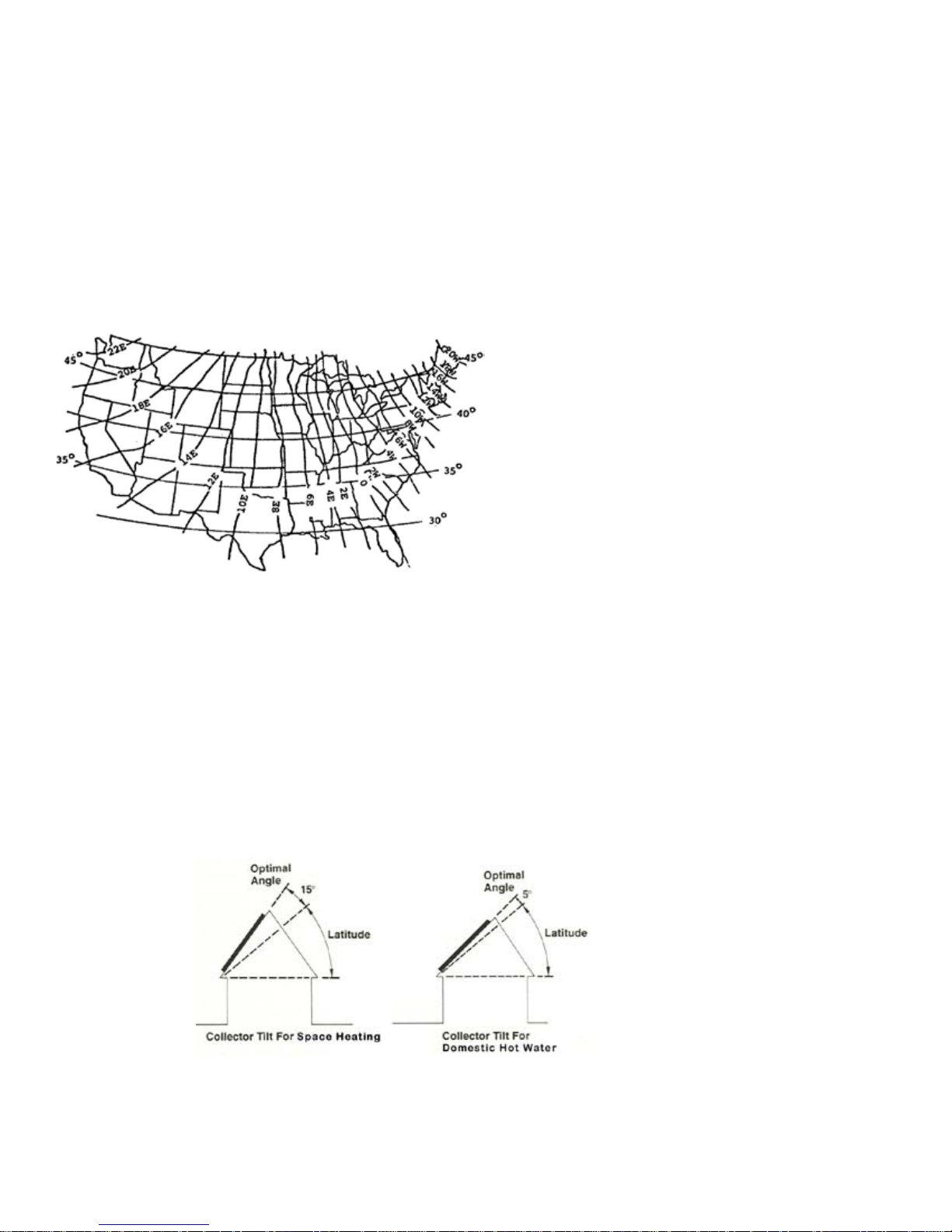
Orientation and tilt are critical to performance. The OVSOL collectors should be oriented (faced) as close
to true south as practical, although they may be faced as much as 20° east or west of true south with less
than 5% loss in capacity. Because the earth’s magnetic eld is not aligned parallel to the earth’s north-
south axis, there are some parts of the United States where the needle of a magnetic compass can point as
much as 20° east or west of true north. There are several ways to determine true south in your area. You
can consult a local surveyor, a plot map in your
local tax ofce, or a recent isogonic chart of the
United States published by the U.S. Coast and
Geodetic Survey. Adjust your magnetic compass reading according to the meridian nearest
to you. Do not use old charts, as there are
annual variations in the readings. When using
a magnetic compass, beware of standing near
large metallic objects or power lines because
they will affect the compass readings.
Shading
Trees, chimneys, dormers, other buildings,
new construction, and even fences may shade the collector array, especially in the winter when sun angles
are low and shadows are long. Be sure the collectors are placed where they will be not shaded by these
obstructions. As a rule, no more than 5% of the collector area should be shaded between the hours of 9:00
a.m. and 3:00 p.m. It is highly advised to make use of a solar site selector while determining suitability for a
collector site.
Angle of Inclination or Tilt Angle
For domestic water, use an optimum tilt of the site’s latitude plus 5°, although the slope may be 10° greater
or less with a capacity loss of under 5% for the system. For a solar space heating system, a steeper tilt
angle is important for optimal winter performance. The steeper tilt will favor winter system operations when
the sun is low in the sky. Therefore, for space heating systems chose a tilt of latitude plus 15°.
The variation of 10° either way will not seriously affect the total annual performance of the system, all other
things being equal.
The following chart will help you determine the tilt angle of roof pitches. For space heating systems, always
082809
9
Page 11
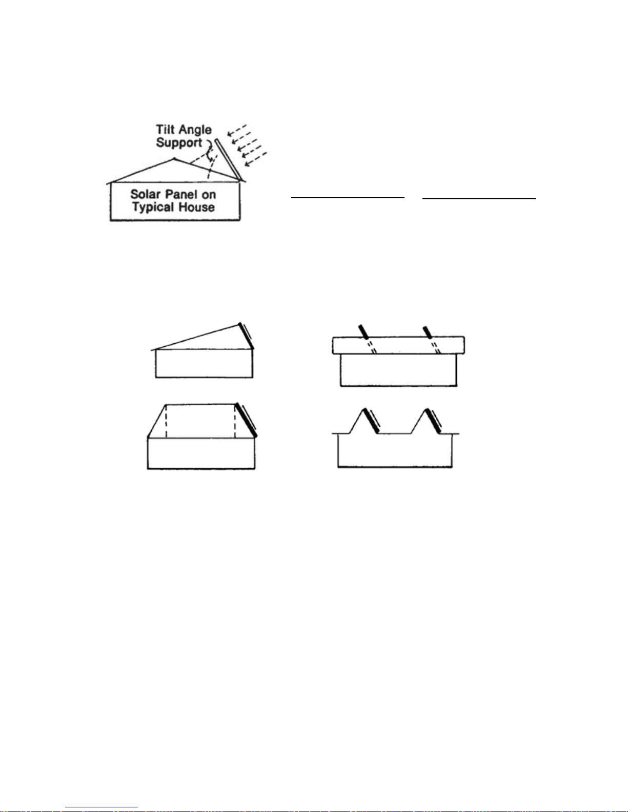
have collectors sloped at optimal tilt for winter performance. Install a collector rack for tilt angle support
whenever necessary.
Roof Pitch Tilt Angle
4/12 18°
6/12 26°
10/12 39°
Integrating with Building Architecture
Maintaining a pleasing appearance to the
building’s architecture is important for adding solar collectors to a roof or on the ground. Most homes are
not oriented well for solar gain, so getting the collectors at just the right orientation and tilt may not integrate
well with the roof lines.
Roof Pitch Tilt Angle
12/12 45°
14/12 49°
22/12 61°
With domestic hot water systems, there may be greater variations to tilt and orientation without large annual
losses, and in some cases may justify ush-mounting collectors. Space heating systems must have a
steep slope and be oriented within 30° of true south. For these larger space heating systems, the layout
should integrate into the roo ine. For new construction, integrating OVSOL collectors into the building’s
roof system should be addressed by the solar designer to the architect.
Shedding Snow
A tilt angle of 50° or more is necessary in regions of heavy snowfall and accumulation. Tilt angles of 50°
and above will shed snow from OVSOL evacuated tube collectors even after severe storms. It is critical in
heavy snow areas that the collectors be sloped to at least a 50° tilt angle. If collectors are installed on a at
roof in an area which receives heavy snowfalls, the lower end of the units should be at least 18” above the
roof level to minimize chances of snow build-up on the bottom end of the collectors.
Shading
To avoid shading by collectors on each other, the front to front dimension must be 2.5 times the highest
point of the front collector.
10
082809
Page 12
section four
Collector Dimensions and Technical Data
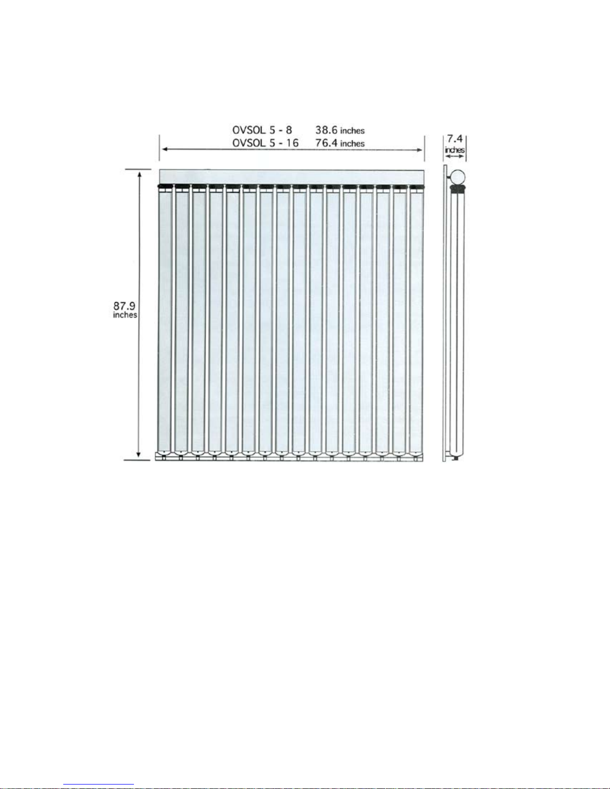
Dimensions of OVSOL 5 8 or 16 tube collectors
Technical Data:
OVSOL 5 - 8: 87.9L x 38.6W x 7.4D inches
OVSOL 5 -16: 87.9L x 76.4W x 7.4D inches
Gross collector area: OVSOL 5 - 8 22.28 sq. ft.
OVSOL 5 - 16 44.67 sq. ft.
Net absorber area: OVSOL 5 - 8 19.37 sq. ft.
OVSOL 5 - 16 38.75 sq. ft.
Gross weight: OVSOL 5 - 8 110 lbs.
OVSOL 5 - 16 220 lbs
082809
Inclination angle: 25° to 90°
Typical operating temperature: 158 - 248 °F
Stagnation temperature: 375 °F
Pressure drop per module
at 1.0 gpm: 0.47 ft/hd
Aluminum nitride absorber
Vacuum grade: 10 mbar
Connection: Dn22 mm tting
11
Page 13
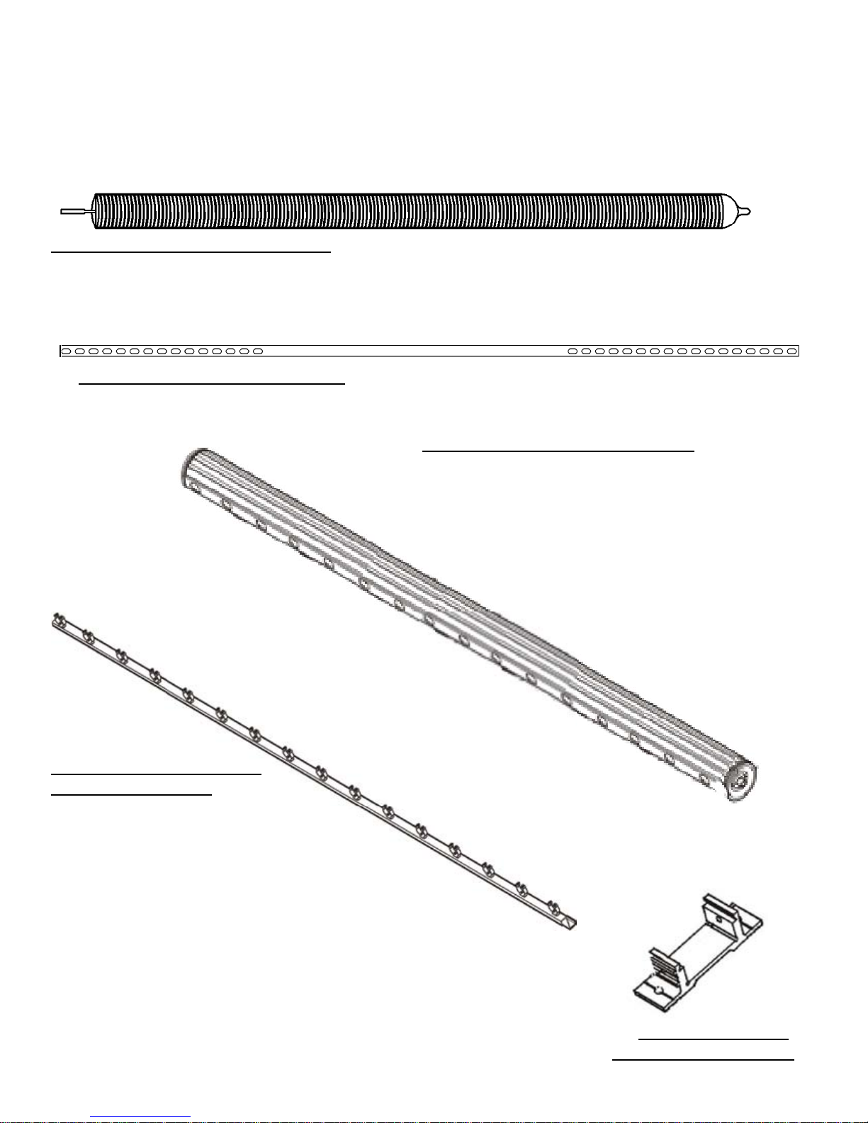
Oventrop OV - 5 Evacuated Tube Solar Thermal Collector
(Eight tube model - 540 00 08, Sixteen tube model 540 00 16)
Contents:
OV - 5, evacuated tube with heatpipe
540 00 08 contains eight (8) tubes
540 00 16 contains sixteen (16) tubes
Dimensions: 79L x 4D inches
2 x Stainless steel collector support rail, 85L x 1.5W x 1.0D inches
Aluminum heatpipe manifold header
540 00 08 contains eight (8) tube connections
Dimensions: 76L x 6D inches
Bottom collector support rail
with steel spring clips
540 00 08 contains eight (8) tube
connections
Dimensions: 76L inches
540 00 16 contains sixteen (16) tube
connections
Dimensions: 38L inches
540 00 16 contains sixteen (16) tube connections
Dimensions: 38L x 5-1/4D inches
Evacuated tubes are shipped eight (8) to a box.
12
2 x Aluminum heatpipe
manifold header bracket
082809
Page 14
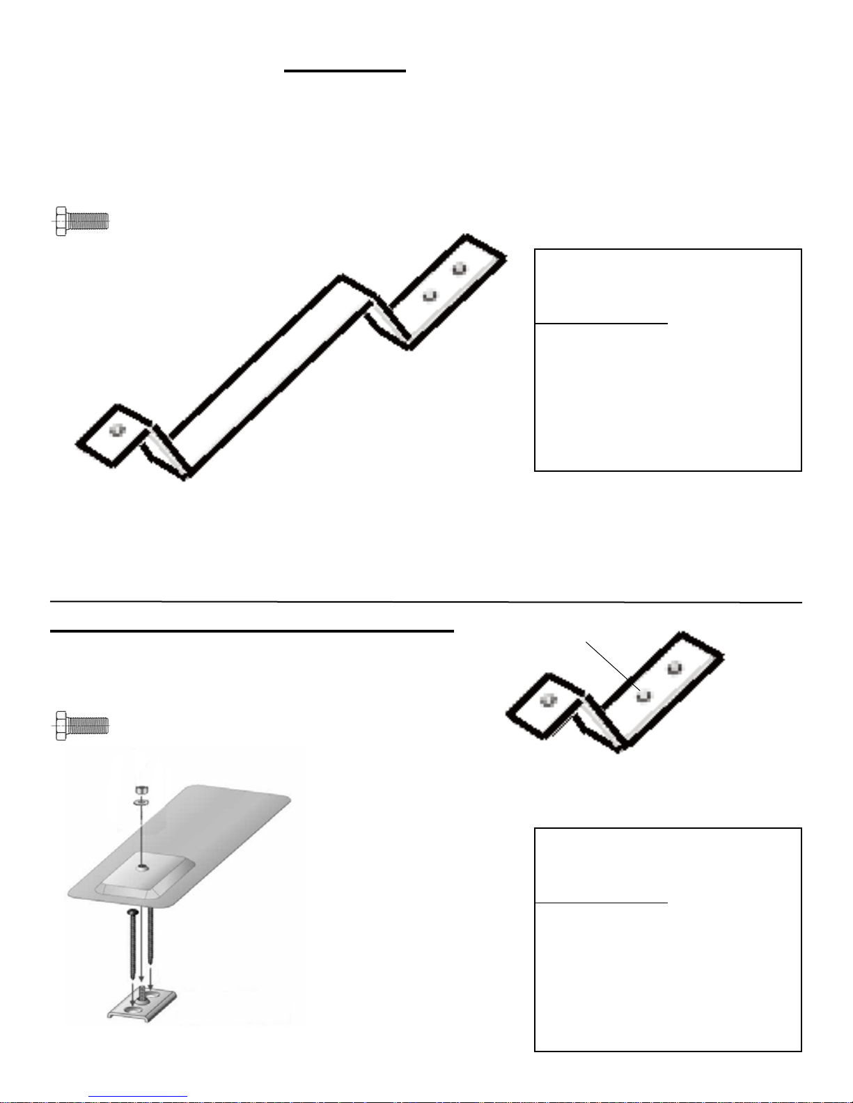
Flush Mounting Kit - Tile Roof
540 00 28-TK
Contents:
4 - Metric thread hex head bolt
540 00 28-TK also contain one bag
of piping connection hardware (not
shown).
The bag contains:
2 - 22 mm connection tee ttings
1 - Manually operated air vent
1 - Temperature sensor thermowell
2 - 22 mm to 3/4 inch adapter pipe
1 - Tube of heatpipe condenser
thermal grease
4 - Steel “tile” roof hooks
Dimensions: 6L x 2W x 4-1/2H inches
Flush Mounting Kit - Shingle Roof
540 00 28-FM
Contents:
4 - Metric thread hex head bolt
4 - Roof mounting ashing kits
Mounting hole
4 - Steel “shingle” roof hooks
Dimensions: 6L x 2W x 4-1/2H inches
540 00 28-FM also contain one bag
of piping connection hardware (not
shown).
The bag contains:
2 - 22 mm connection tee ttings
1 - Manually operated air vent
1 - Temperature sensor thermowell
2 - 22 mm to 3/4 inch adapter pipe
1 - Tube of heatpipe condenser
thermal grease
082809
13
Page 15
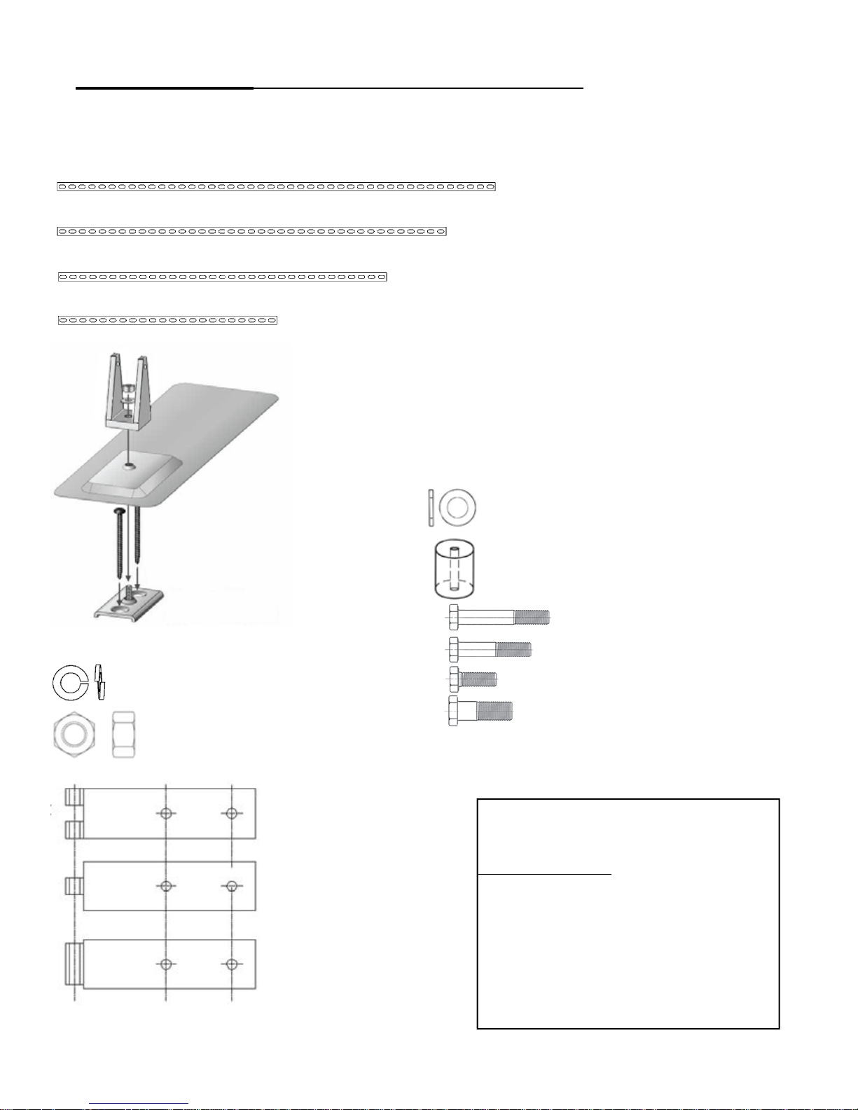
Adjustable Rack for evacuated tube collectors
- for eight (8) tube collector, 540 00 28-8
- for sixteen (16) tube collector, 540 00 28-16
Contents:
2 - Back support rail (A) 66 inches
1 - Back cross brace 58 inches
(540 00 28-16 only)
1 - Back cross brace 50 inches
1 - Back cross brace 32 inches
(540 00 28-8 only)
4 - Roof mounting bracket and ashing kits
22 - Split lock washer
Dimensions: 5/16 D.nom. inches
22 - Hex nut
Dimensions: 5/16 D.nom. inches
2 - Hinge A
2 - Hinge B
4 - Hinge C
44 - Steel at washer
Dimensions: 3/8 D.nom. inches
8 - Aluminum spacer bushing
Dimensions: 1.0H x 1.0D inches
6 - 5/16 x 2.5 inch hex head bolt
8 - 5/16 x 2 inch hex head bolt
8 - 5/16 x 1 inch hex head bolt
4 - 1/2 x 1.5 inch hex head bolt
540 00 28-8 and 540 00 28-16 also
contain one bag of piping connection
hardware (not shown).
The bag contains:
2 - 22 mm connection tee ttings
1 - Manually operated air vent
1 - Temperature sensor thermowell
2 - 22 mm to 3/4 inch adapter pipe
1 - Tube of heatpipe condenser thermal
grease
14
082809
Page 16
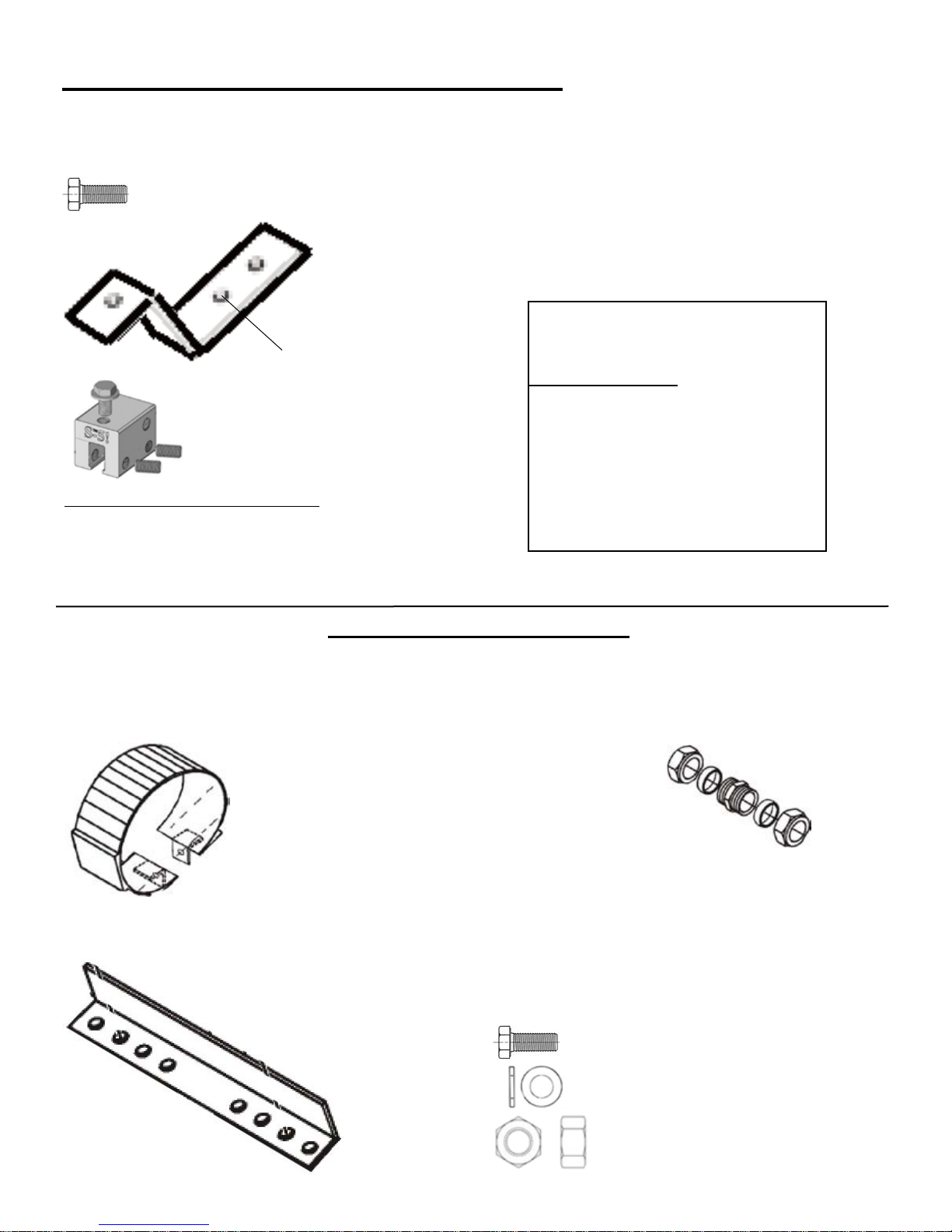
Flush mounting kit - Metal Seam Roof
540 00 28-MS
Contents:
4 - Metric thread hex head bolt
4 - Steel roof hooks
Dimensions: 6L x 2W x 4-1/2H inches
540 00 28-MS also contain one bag
of piping connection hardware (not
Mounting hole
4 - Metal seam clamp kit
Metal seam clamp kit contains:
1 - Aluminum clamp block
1 - 3/8 x 3/4 inch hex head bolt
1 - Flat washer, 3/8 inch
4 - 3/8 x 3/4 inch set screw
shown).
The bag contains:
2 - 22 mm connection tee ttings
1 - Manually operated air vent
1 - Temperature sensor thermowell
2 - 22 mm to 3/4 inch adapter pipe
1 - Tube of heatpipe condenser
thermal grease
Connection Kit for evacuated tube collectors
540 00 21, for 540 00 08 and 540 00 16
Contents:
1 - Extruded aluminum manifold sleeve
Dimensions: 2W x 5-1/4D inches
1 - 22 mm straight compression coupling
1 - Bottom support rail connection L-bracket
Dimensions: 8L x 1.0W x 1.0H inches
2 - Metric thread hex head bolt
082809
2 - Metric thread at washer
2 - Metric thread hex head nut
15
Page 17
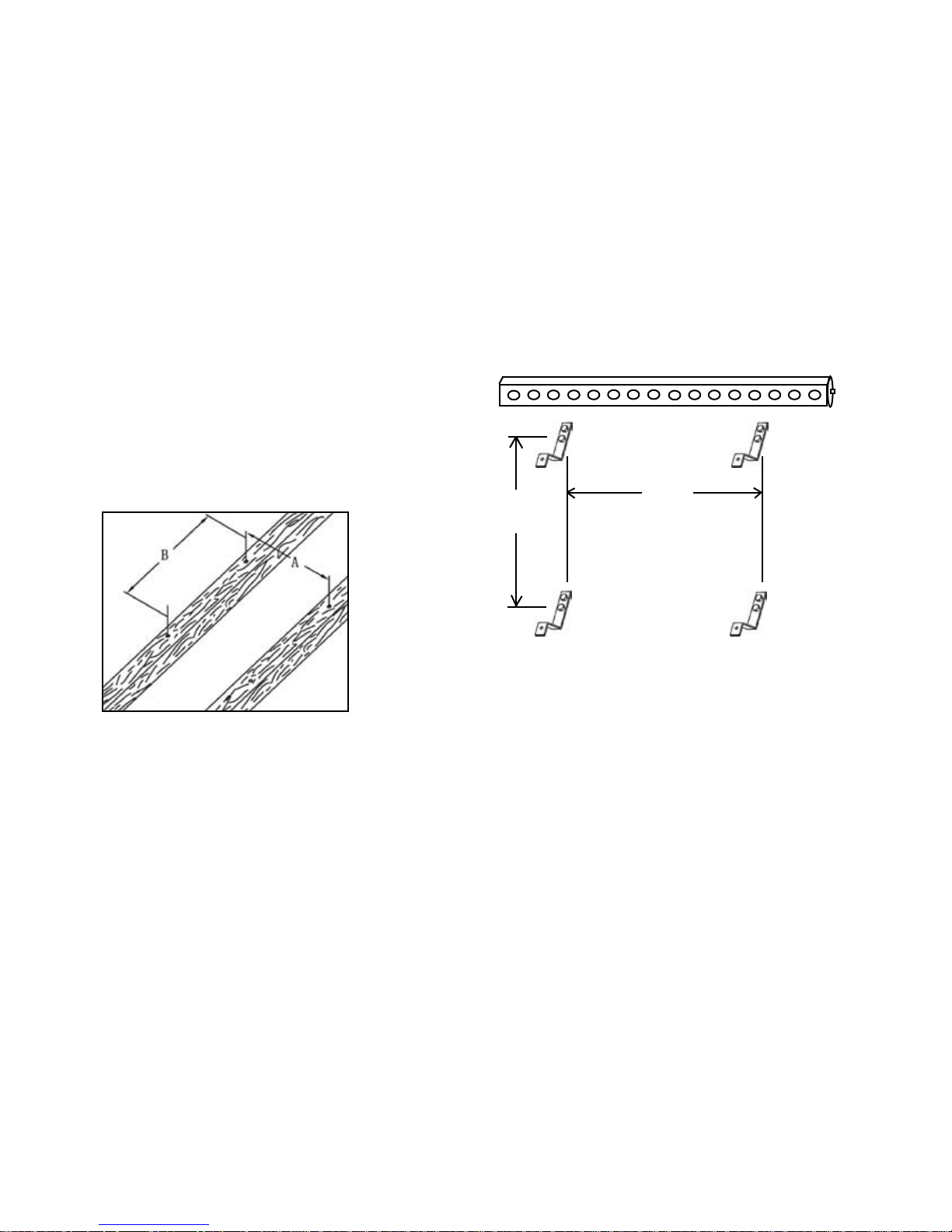
section ve
Collector Assembly
Flush Roof Mounting
Collector foot measuring details for
Shingle Roof Kit (540 00 28-FM, Tile Roof Kit (540 00 28-TK), and
Metal Seam Roof Kit (540 00 28-MS)
Measure the Installation Area
Once the collector location is determined, lay out the four mounting feet of each collector within
the dimensions listed below:
8 tube collector: ‘A’ = 16 to 25 inches;
‘B’ = 63 to 80 inches
center manifold on collector feet spacing
16 tube collector: ‘A’ = 48 to 66 inches; ‘B’ = 63 to 80
inches
B
63” - 80”
Flush Mounting on Asphalt Shingles (for mounting with supplied ashing kit see next page)
Shingle Roof Kit (540 00 28-FM)
Mounting of Collector Feet
Collector feet may be lag bolted into the roof rafters. Since most roof trusses or rafters are built on 16-inch
centers, locate the comers so that the width dimension falls on the 16-inch center. To locate the nearest
rafters, use a stud nder. Once the rafter is located, drill a small diameter pilot hole to verify the rafter’s
center line. Be sure to lift the upper shingle and predrill into the underlying (covered) row to prevent water
leaks. Lift shingles carefully to avoid tearing. Always seal pilot holes not being used.
8 tube: 16” - 25”
16 tube: 48” - 66”
A
Roof Hooks
Mark the pilot hole for the center line of the roof rafter or truss. Next, pre-drill two holes for each collector foot
into the center line of the rafter using a drill bit smaller in diameter than the lag bolt supplied. Apply a
generous amount of polyurethane sealant around and within the pre-drilled hole. Screw the collector feet in
place. Avoid over-tightening and stripping the lag bolts. You may apply a small amount of sealant to the lag
bolt heads to prevent water leakage. The important thing is to locate the collector feet atop roof joists so that
the weight of the collector is supported. Select rafters so that two tubes will overhang to the right and left for
an 8-tube module. For a 16-tube module, you may allow up to four tubes to overhang to the left and right of
the rafters. The overhangs are necessary for better weight distribution.
16
082809
Page 18
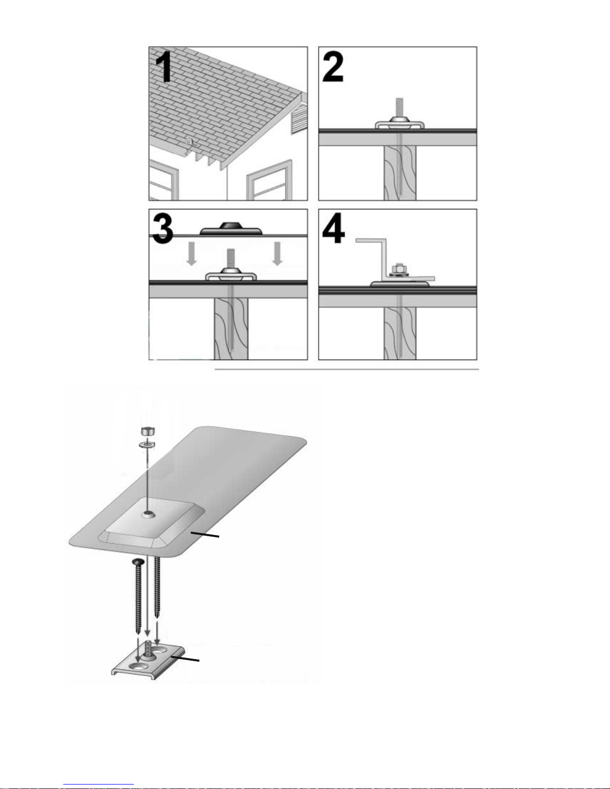
Flashing
The bracket is to be fastened
to the base plate through the
hole closest to the vertical.
Installing the collector feet and ashing
No need to remove any shingles to install the ashing.
Base plate is rst screwed into a roof rafter or block and
ashing is slided under the roof shingle covering the
installed base plate.
Tools Required:
- Cordless drill with #2 square drive bits
- Tape measure, stud nder, chalk line
1. Locate the rafters and snap horizontal and vertical lines
to mark the installa-tion position for each upper mounting
foot. Blocks, installed in the attic, may have to be positioned between the rafters to make sure the base plate has
a structural member to screw into.
Base Plate
Sealant must be applied to
any penetration of the roof
082809
2. Install the base plate with the square drive screws. Mark
the screw locations and apply polyurethane sealant at
the penetrations. The baseplate must be securely at-
tached atop the roof and into the roofs structural member.
3. Install ashing by sliding it into place under then next
row of shingles. cover base plate with the ashing pocket .
4. Install the collector foot onto the ashing using
neoprene-bonded washer and stainless locking nut.
17
Page 19
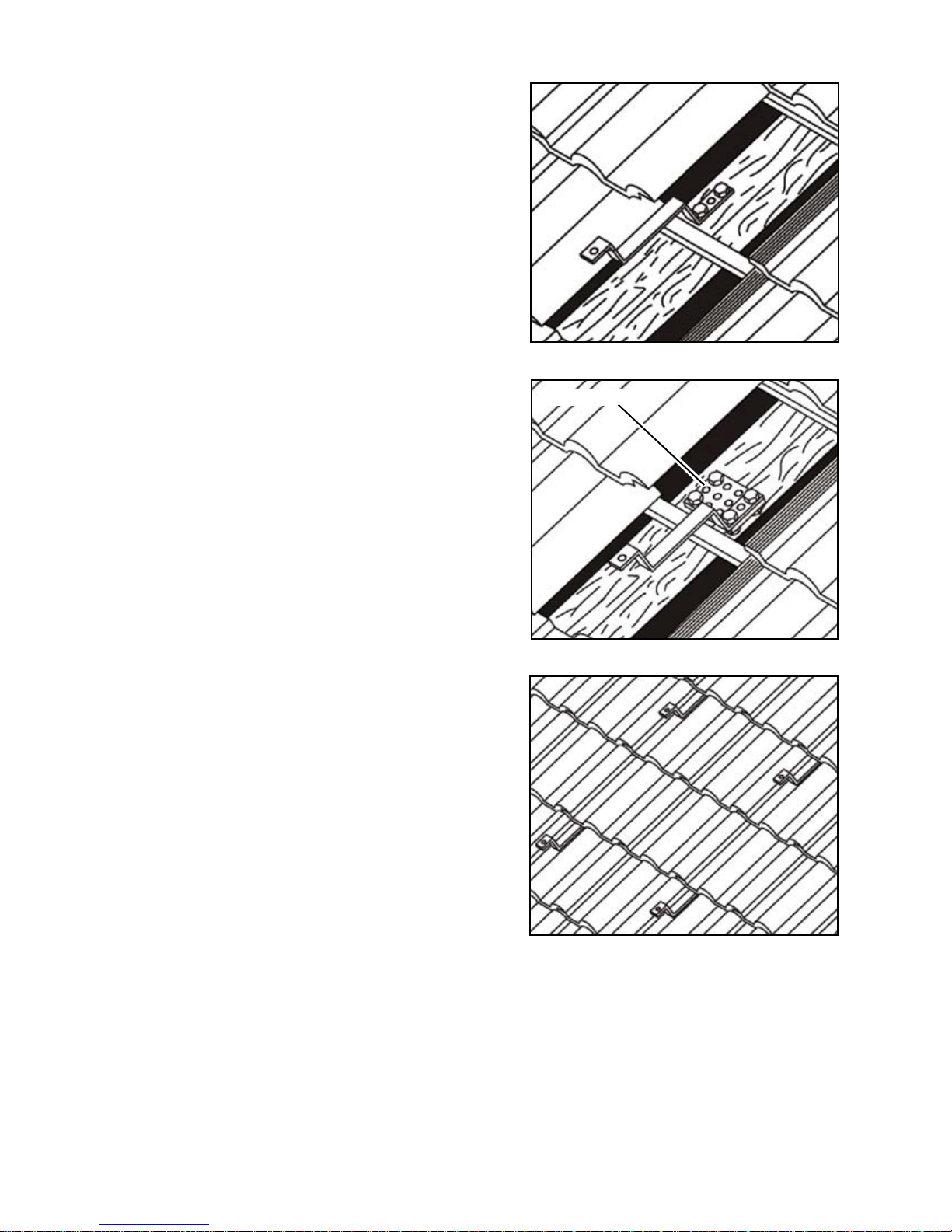
Flush Mounting on Tile Roofs
Tile Roof Kit (540 00 28-TK)
Mounting of Collector Feet
On a tiled roof, it is generally easy to locate the rafters
by simply lifting out individual tiles at the desired foot
placement. You will see the where the sheeting has been
nailed into the roof rafters below. This is your visual
indicator for the rafters. Predrill small pilot holes to nd
the center line of the rafters.
Install four collector feet by lag bolting feet into roof rafter.
If necessary, use perforated plates to extend the tile roof
hooks from the roof rafters, or lag bolt into spanners
or blocks between the rafters, to get the width needed
between collector feet.
Place the feet vertically so that the rst angle on the roof
hook clears the top edge of the tile resting below.
Apply a generous amount of polyurethane sealant in
and around the lag bolt holes before tightening bolts
into place. Seal any other test holes made for pre-siting
rafters.
The collector feet must be aligned vertically and
horizontally.
Perforated plate
Reinstall tiles around the collector feet.
See page 9 for ush mounting frame assembly
instructions.
18
082809
Page 20
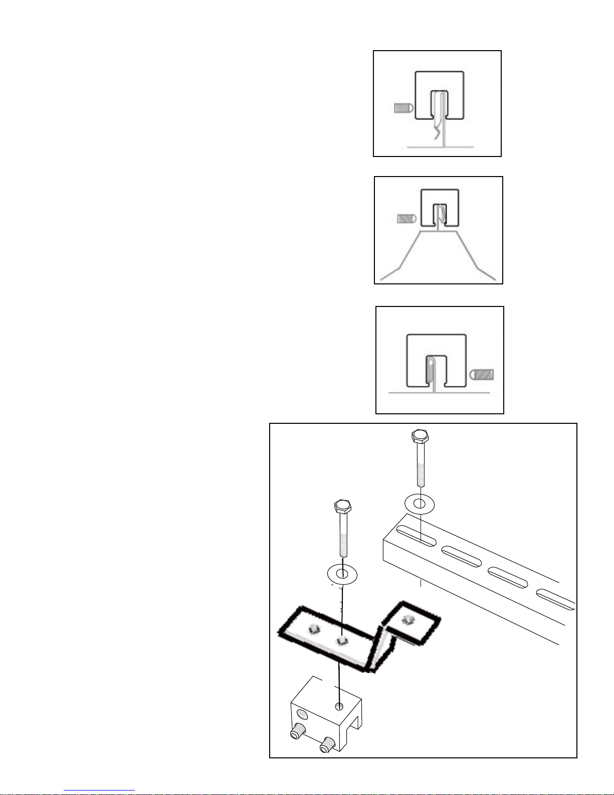
Flush Mounting to a Metal Seam Roof
Metal Seam Roof Kit (540 00 28-MS)
Mounting of Collector Feet
For each collector support rail, attach the rectangular
blocks in the hole fourth from the top and rst from the
bottom as shown by the image below.
On the top end in holes 1 and 3, using the square nuts,
attach the manifold bracket.
Secure the rails to the seams of the roof as seen in
the illustrations. Select seams so that two tubes will
overhang to the right and left for an 8-tube module.
For a 16-tube module, you may allow up to four tubes
to overhang to the left and right of the seams. The
overhangs are necessary for better weight distribution.
Once the rails are secured to the roof seams, the tube
support rail should be bolted into the second holes
from the bottom.
After installing the tube support rail, slide the manifold
through the manifold brackets at the top of the
collector.
Insert the two outer tubes and check for square lines.
Insert remaining tubes from one side to the other.
The bracket is to be fastened to
the metal seam clamp through
the hole closest to the vertical.
082809
19
Page 21
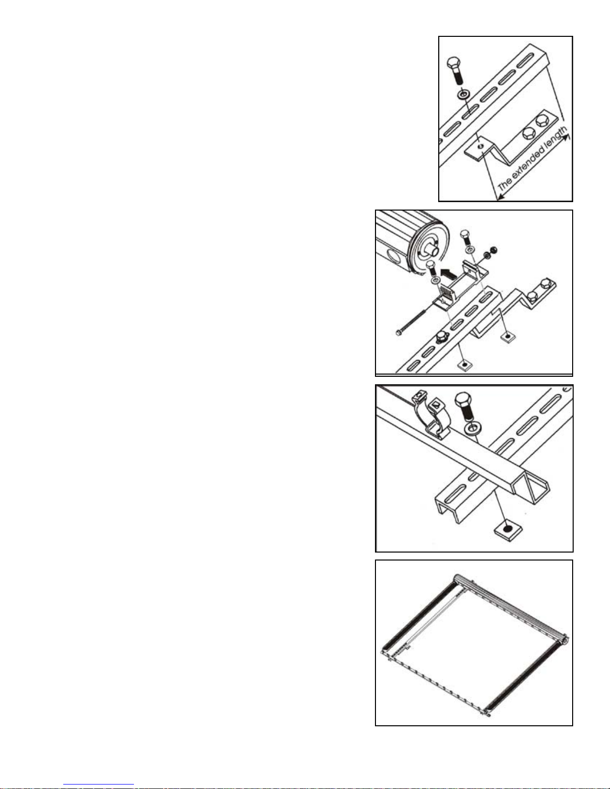
Assembling the Collector Frame
Place the collector rail on the collector top and bottom
feet and install rail where it can be lined up with the collector feet bolt holes. If possible, choose the fourth hole
from the top of the verticle frame to set the bolt into the
top collector foot.
Tighten bolts.
Attach the manifold support into the rst and third holes
of the vertical collector frame. Bolt the manifold support
into the collector frame with square nuts.
Bolt the bottom tube support with square nuts on the
second hole from the bottom of the vertical collector
frame; tighten bolts to avoid the bottom support from
slipping. Line up the collector clips at the bottom tube
support rail to the manifold dry well ttings for the
evacuated tubes to line up square. There may need to
be a verticle adjustment, so don’t tighten the bolt
completely until a tube has been pre-t.
Install one vacuum tube on either end. Using corner-tocorner measurements, ensure the collector assembly is
squared.
Install each vacuum tube from one end to the other.
20
082809
Page 22
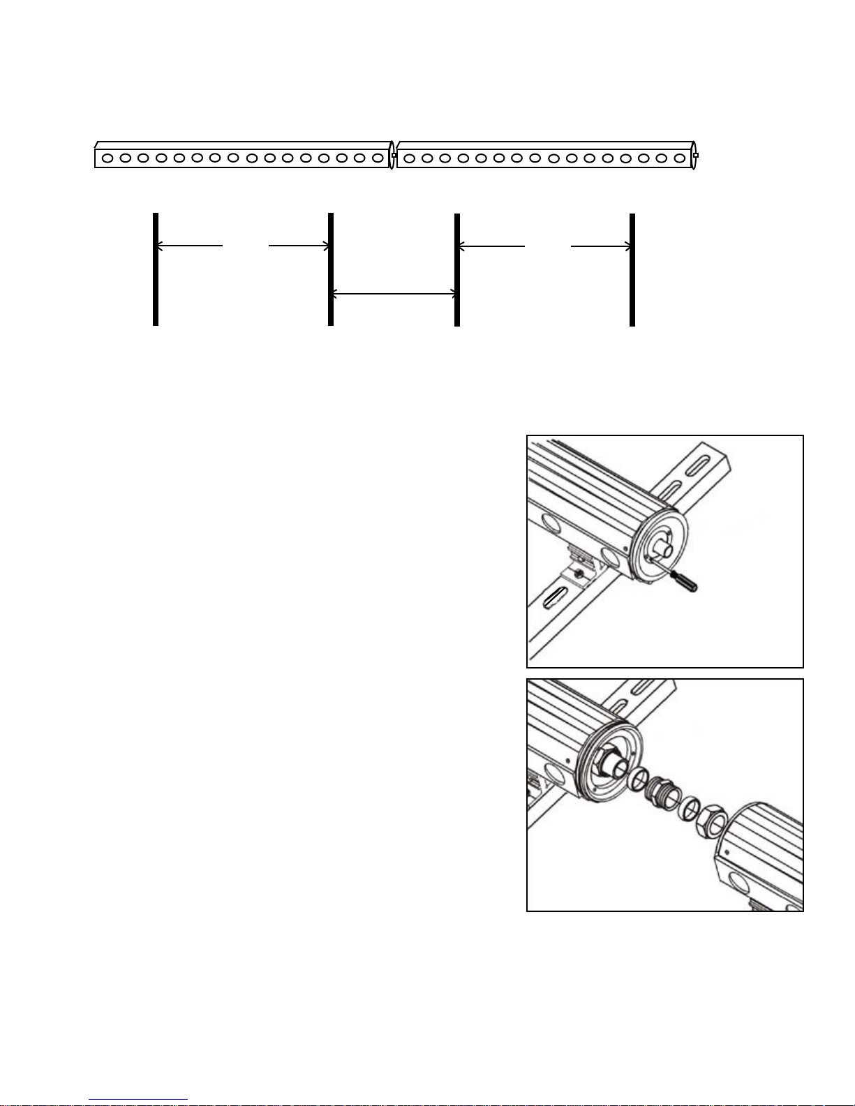
Multiple Collector Array Dimensions
ManifoldManifold
Rail
A
16 tube: 48”
A
Distance Between Rails
Adding Collectors
Collector Extension Kit
If there is more than one collector, you may add a coupler
between the manifold ends to connected them together.
Disassemble the end cover with screwdriver.
Rail
C
16 tube: 28”
C
Distance Between Collectors (Rails)
Rail
16 tube: 48”
Distance Between Rails
Rail
A
A
Connect two header boxes with compression
couplings supplied — keep distance of 2 - 1/8” between
the two header boxes for the manifold connector cuff.
082809
21
Page 23
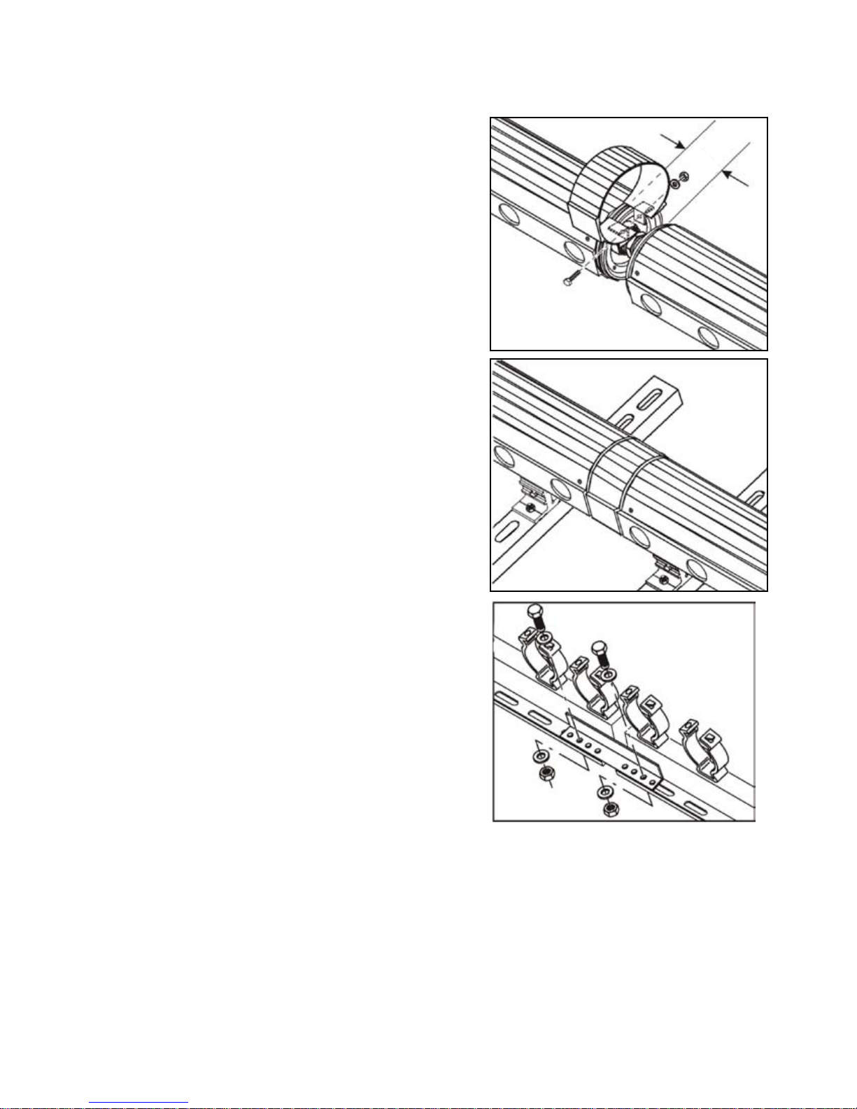
Collector Extension Kit continued
Insulation in the collector cuff cavity. Use high
temperature (300F+) elastomeric foam insultube,
or comparable.
Install and attach the connection cuff.
Tighten the screw slot bolt and nut to clamp the connection
cuff.
2- 1/8”
The bottom rails are connected with a bottom support
connection.
Screw nut and bolt the bottom support connector into place
between the two collector bottom rails.
22
082809
Page 24
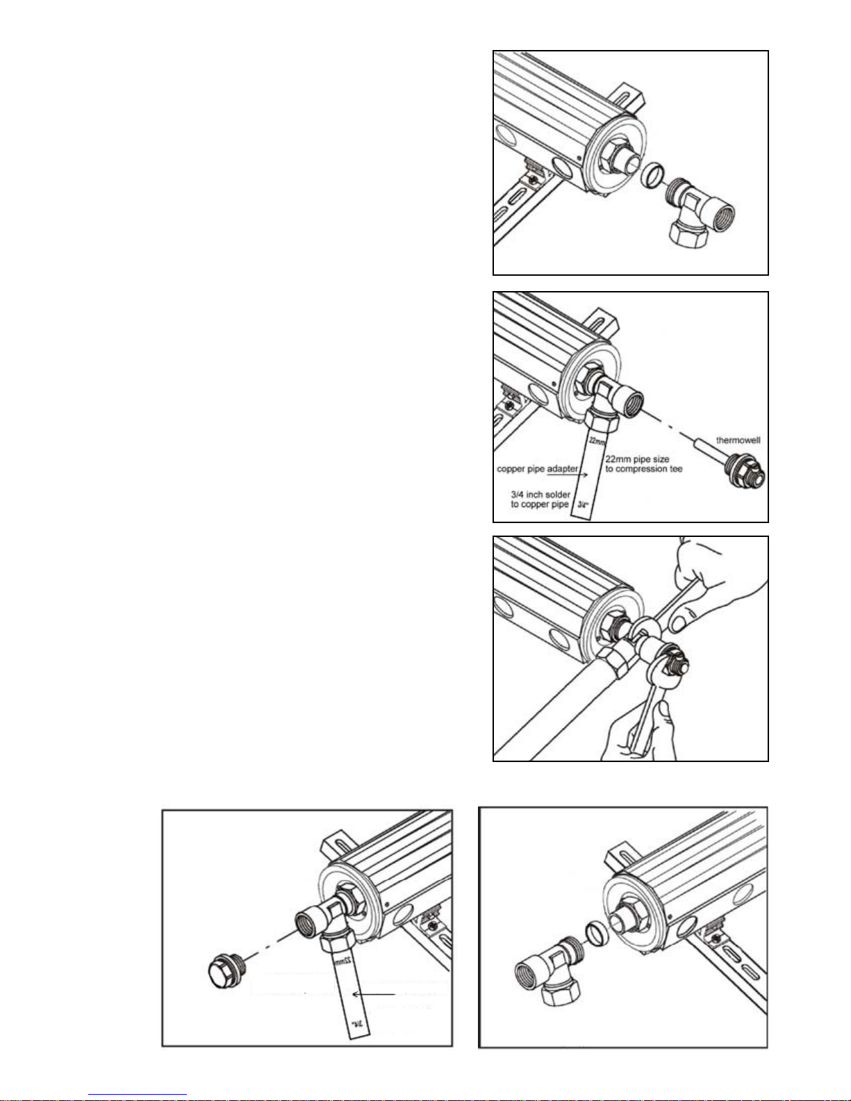
Connect Piping to the Manifold
With each roof mounting kit, there are adapters to pipe to
the manifold. Included are:
l Two compression tees to attach to the supply and return
terminations on each collector manifold or collector array;
l Two copper pipe adapters that adapt from 22mm copper
pipe size (at compression tee) to 3/4” copper pipe. Also
included in some roof kits are two stainless steel exible
hoses and additional compression couplings for copper pipe
adapters.
NOTE: Use 1/2” copper supply and return for collectors
with up to 24 tubes (one 8- and one 16-tube collector) and
3/4” copper for collectors with a 4- to 16-tube collector array.
Preferably use Type L. Do not use PEX plastic tubing.
PEX tubing cannot withstand temperatures above 200°F
and will fail. Always insulate outdoor tubing with high
temperature Insultube and weather proong against UV
degradation. Use insulation with a wall thickness of at least
3/4”.
Thermowell must
be soldered in
place.
Install compression tees at supply and return on collector
manifold. Make sure the compression ring is well
onto the copper pipe terminating the manifold so that
the compression ring will not slide off the pipe as the
compression nut is tightened.
Install the Thermowell, which is for the collector sensor, on
the return outlet tee. Solder the threaded Thermowell into
the tee before installing the compression tee to the header.
Smear some heat transmission paste on the sensor and
insert the sensor into the Thermowell. Lock sensor into
place with set screw on the Thermowell.
Install the manual air vent on the manifold’s supply inlet
tee. If the piping rises above the collector on a closed loop
system, add an additional manual air vent at the highest
point of the loop.
Supply side
manual
air vent
22mm pipe size
to compression tee
082809
copper pipe adapter
3/4 inch solder to
copper pipe
23
Page 25
Section Six
Adjustable Rack Mounting Kit
540 00 28-16
Roof Mounting Assembly
Rack Assembly
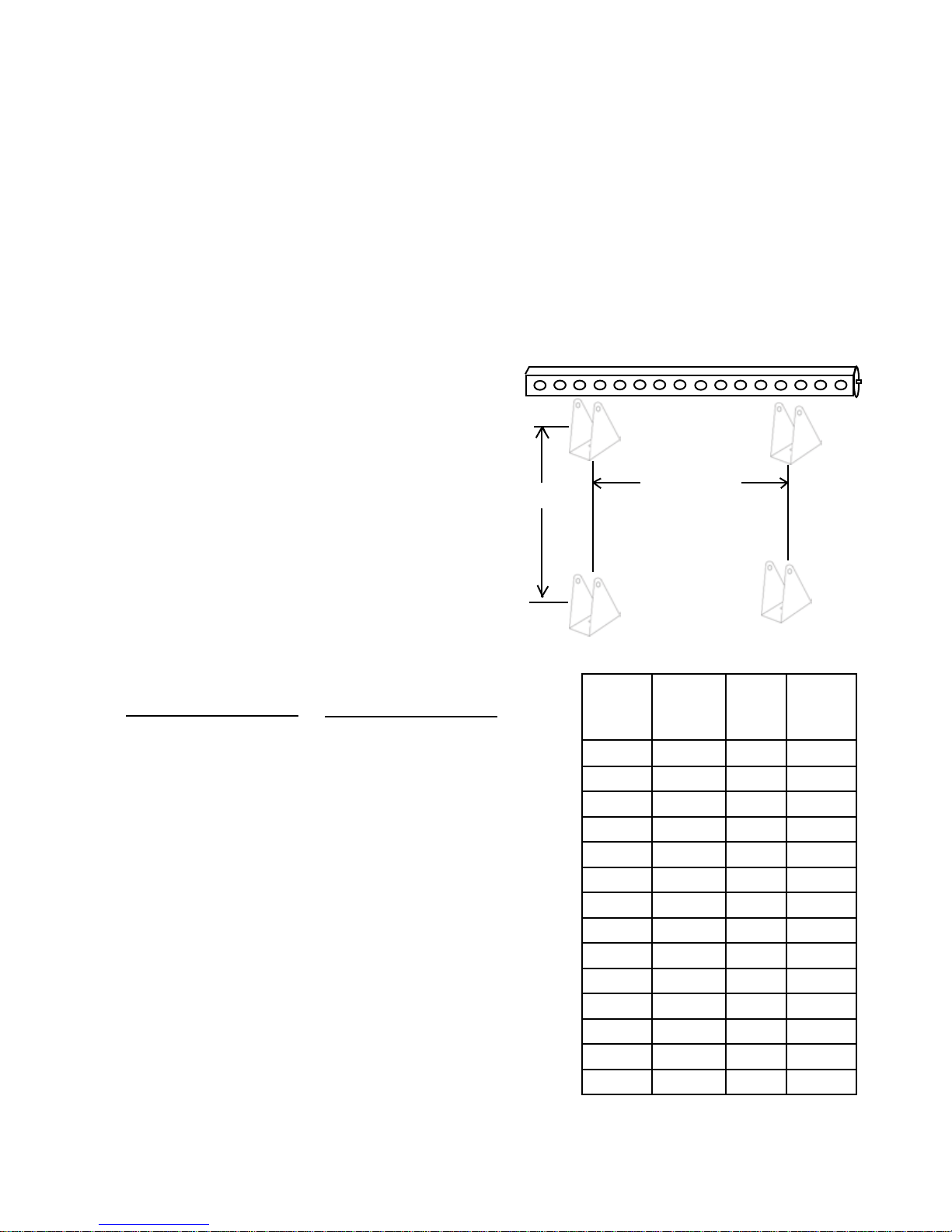
Measure the Installation Area
Once the collector location is determined, lay out the four mounting feet of each collector within
the dimensions listed below:
Center manifold on collector feet spacing
Measures (B) the “on center” distance between the front and back collector mounting feet.
The width between the feet should be 48
inches on center for a 16 tube collector.
For the 8 tube collector, the width between
the feet should be 32” on center.
B
Maximum
dimensions
8 tube: 32”
16 tube: 48”
and 540 00 28-8
Roof Pitch Tilt Angle
4/12 18°
6/12 26°
10/12 39°
Roof Pitch Tilt Angle
12/12 45°
14/12 49°
22/12 61°
The column (“A” Inches) measures the length of
the rear support legs.
The column (“B” Inches) measures the dimension
between front and rear feet (center to center)
where the hinge leaf barrels will be set for
accurate tilt.
The width between the feet should be maximum
48” on center for 16 tube collector. For the 8 tube
collector, the width between the feet should be
maximum 32” on center.
Collector mounting feet
Rack
Angle in
degrees
0 N/A N/A 75”
10 11” 4 74”
15 17” 8 72”
20 23” 10 70”
25 30” 14 68”
30 35” 16 65”
35 41” 19 62”
40 46” 22 58”
45 51” 24 53”
50 56” 27 48”
55 60” 28 43”
60 63” 31 40”
65 67” 32 40”
70 72” 34 40”
“A”
Inches
number
of total
slots
“B”
Inches
24
082809
Page 26
Installing the upper mounting brackets
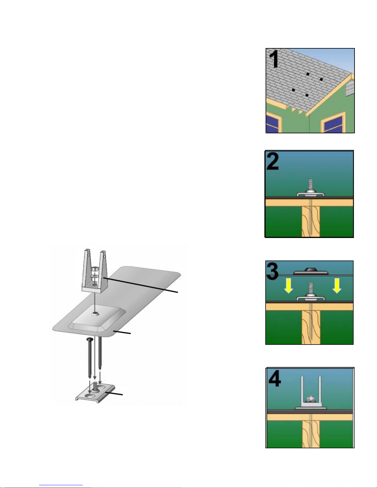
Installing the collector feet and ashing
No need to remove any shingles to install the ashing. Base plate is rst screwed
into roof rafter or block and ashing is slided under the roof shingle covering the
installed base plate.
Tools Required:
- Cordless drill with #2 square drive bits
- Tape measure, stud nder, chalk line
1. Locate the rafters and snap horizontal and vertical lines to mark the installa-
tion position for each upper mounting foot. Blocks, installed in the attic, may have
to be positioned between the rafters to make sure the base plate has a structural
member to screw into.
2. Install the base plate with the square drive screws. Mark the screw locations
and apply polyurethane sealant at the penetrations. The baseplate must be
securely attached atop the roof and into the roofs structural member.
3. Install ashing by sliding it into place under then next row of shingles. cover
base plate with the ashing pocket .
4. Install the collector foot as shown below using neoprene-bonded washer and
stainless locking nut.
Collector Feet
Flashing
Base Plate
Sealant must be applied to
any penetration of the roof
082809
25
Page 27
Collector Frame Assembly Instructions
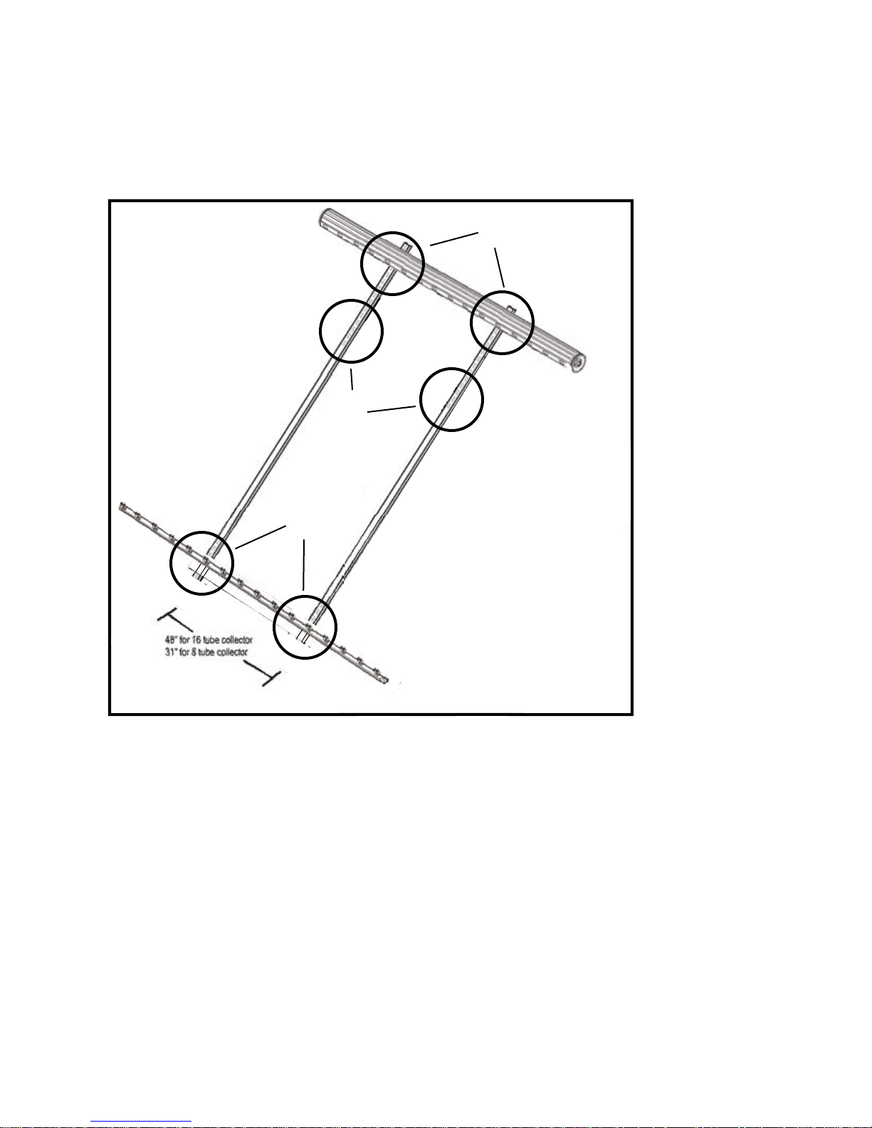
Adjustable rack collector mounting kit - 540 00 28-16 and 540 00 28-8
1
3
A
2
Maximum
dimensions
For adjustable tilt mounting
Steps 1 through 6 should be
completed before beginning
assembly on the roof
26
082809
Page 28
Steps 1, 2, and 3:
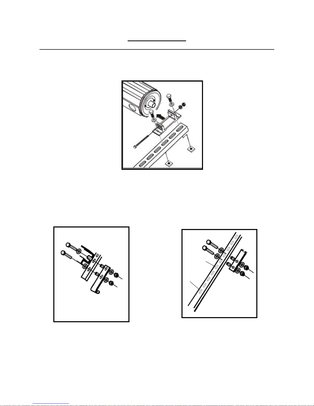
Attaching hinge leaves A and C to the stainless steel collector support rail.
Parts: 5/16 x 2.0 inch bolts, 5/16 inch nuts, 3/8 inch washers, 1.0 inch aluminum
spacers, hinge leaves A, hinge leaves C, assembled collector frame from step 1
1
Step 1a: Attach the header
manifold bracket with bolts
through holes 1 and 3 at
the top of the rail using the
supplied square nuts
2
Step 2: Attach hinge leaf C
through the rst two(2) holes
at the bottom of the rail
Step 1b: Attach manifold by
sliding the mounted manifold
bracket and rail along the
manifold
#5
#1
3
Step 3: Attach hinge leaf
A through the sixth(6) and
seventh(7) holes from the
center of the rail.
082809
27
Page 29
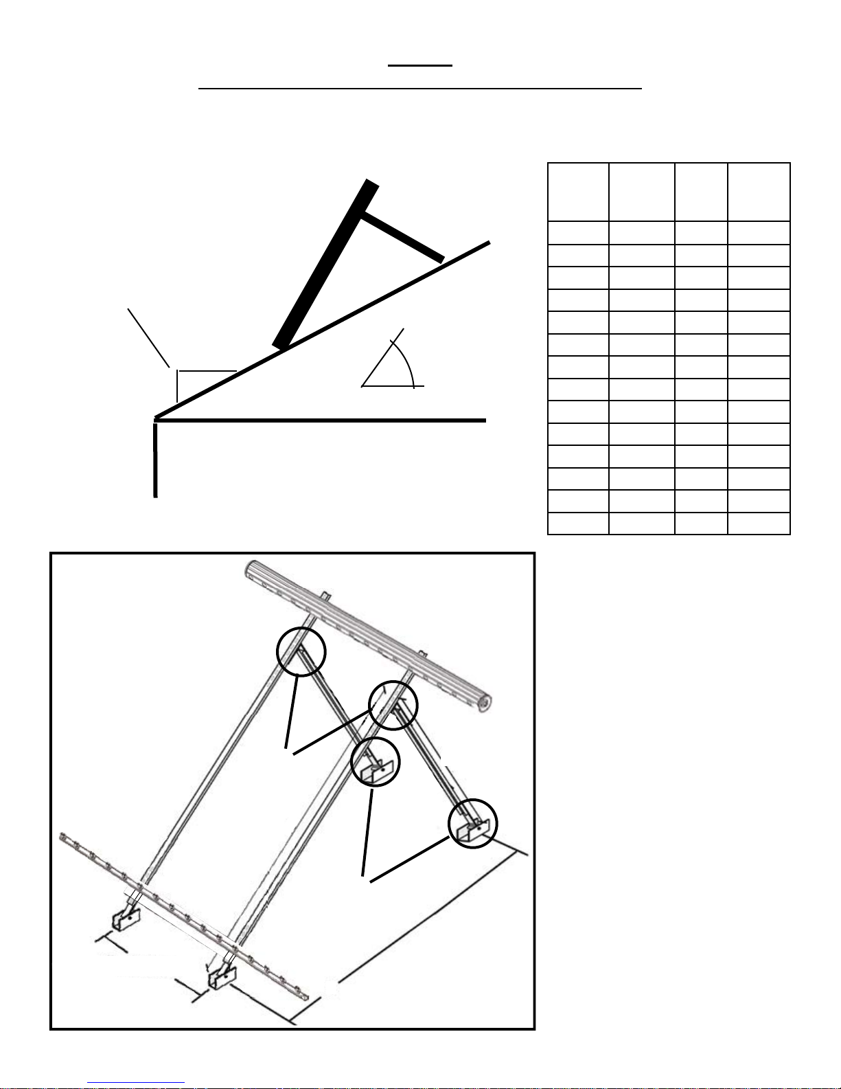
Step 4:
Sizing and cutting the back support rails to length ‘A’
Parts: Back support rail (A) 66 inches
Roof Pitch
Angle
Rise
Collector
Rack Tilt
Angle
Run
Collector tilt angle
66” piece cut to
dimension “A”
Roof line
Rack
Angle in
degrees
0 N/A N/A 75”
10 11” 4 74”
15 17” 8 72”
20 23” 10 70”
25 30” 14 68”
30 35” 16 65”
35 41” 19 62”
40 46” 22 58”
45 51” 24 53”
50 56” 27 48”
55 60” 28 43”
60 63” 31 40”
65 67” 32 40”
70 72” 34 40”
The column (“A” Inches) measures the length of
the rear support legs.
“A”
Inches
number
of total
slots
“B”
Inches
48” for 16 tube collector
31” for 8 tube collector
Maximum
dimensions
The column (“B” Inches) measures the
dimension between front and rear feet (center to
center) where the hinge leaf barrels will be set
for accurate tilt.
The width between the feet should be maximum
48” on center for 16 tube collector. For the 8
tube collector, the width between the feet should
be maximum 32” on center.
5
75”
A
6
B
28
082809
Page 30
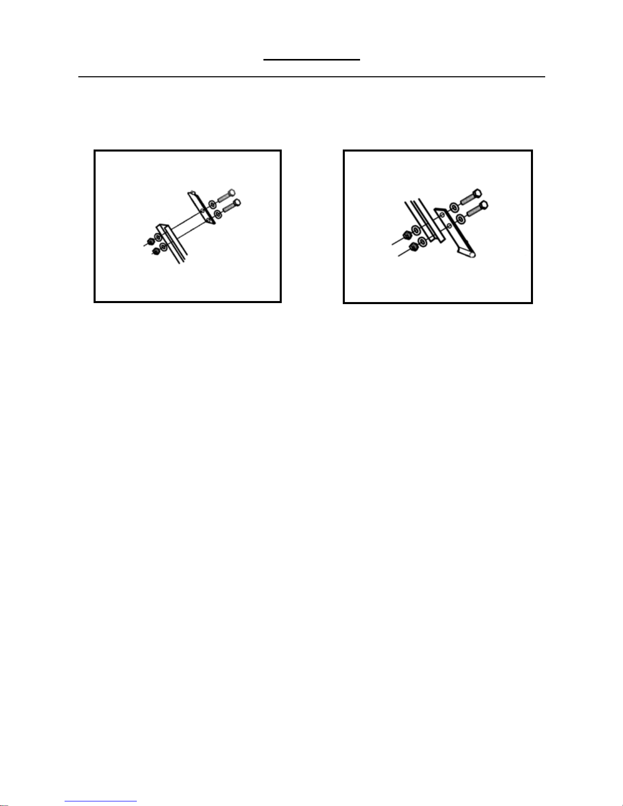
Steps 5 and 6:
Attaching hinge leaves B and C to the piece of strut cut to length in step 7.
Parts: 5/16 x 1.0 inch bolts, 5/16 inch nuts, 3/8 inch washers, hinge leaves A,
hinge leaves C, 66 inch piece of strut cut to length in step 4
5
Step 5: Attach hinge leaf B to the
top end of the back support rail
6
Step 6: Attach hinge leaf C to the
bottom end of the back support rail
082809
29
Page 31
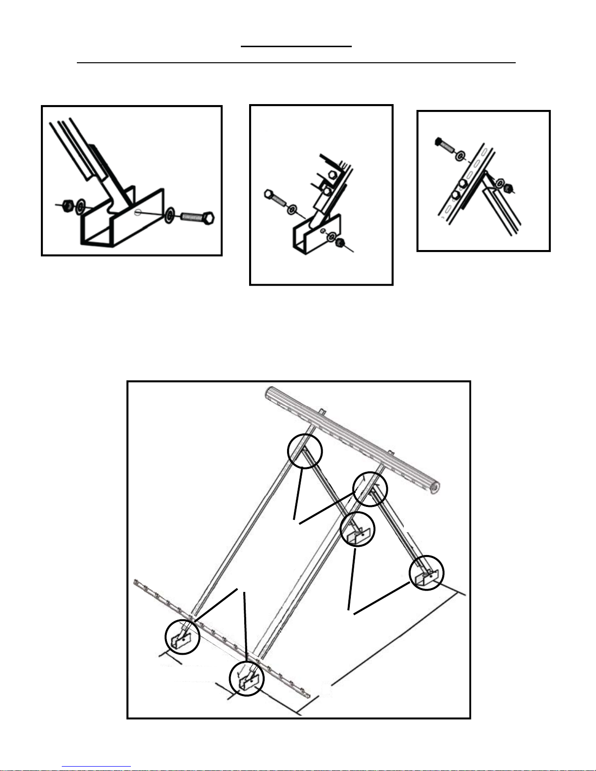
Steps 7, 8, and 9:
Attaching hinge leaves A to B and leaves C to the aluminum bracket feet.
Parts: 5/16 x 2.5 inch bolts, 5/16 inch nuts, 3/8 inch washers, piece from step 6
(back support rail), piece from step 3 (assembled collector frame)
7
Step 7: Align hinge leaf C
(from back support rail) with
the holes in the walls of the
rear foot bracket and insert
bolt.
8
Step 8: Align hinge leaf C
(from front collector rail) with
the holes in the walls of the
front foot bracket and insert
bolt.
9
Step 9: Align hinge leaf
B (from back support rail)
with hinge leaf A (from front
collector rail) and insert bolt.
48” for 16 tube collector
31” for 8 tube collector
Maximum
dimensions
30
9
8
75”
7
B
A
082809
Page 32
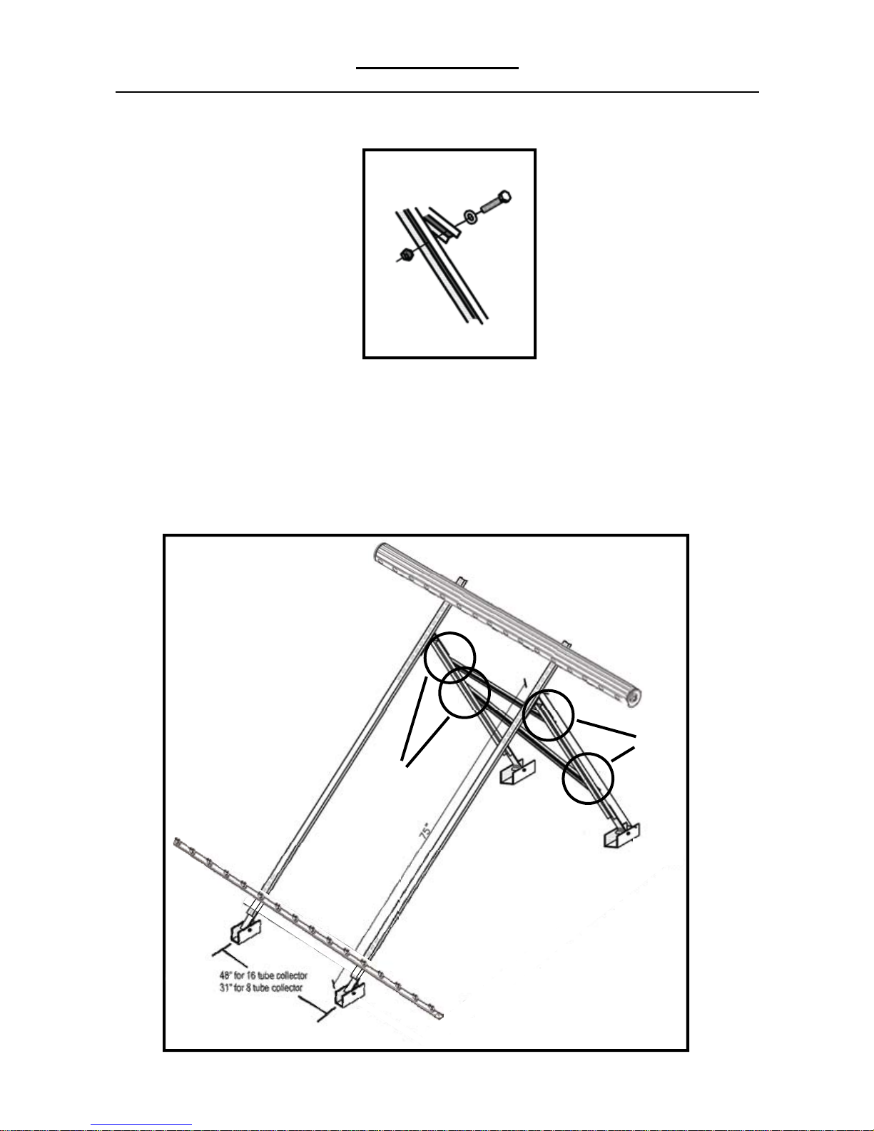
Steps 7, 8, and 9:
Attaching hinge leaves A to B and leaves C to the aluminum bracket feet.
Parts: 1/2 x 1.5 inch bolts, 1/2 inch nuts, 1/2 inch washers, pieces from step 9
(assembled collector frame)
10
Step 10a: Using the 1/2
inch bolt sets, attach the
50” (32” for 8 tube collector)
back cross bracing piece,
horizontally, to the collector
10
Step 10b: Using the 1/2
inch bolt sets, attach the
58” (50” for 8 tube collector)
back cross bracing piece,
diagonally, to the collector
10
Maximum
dimensions
082809
31
Page 33
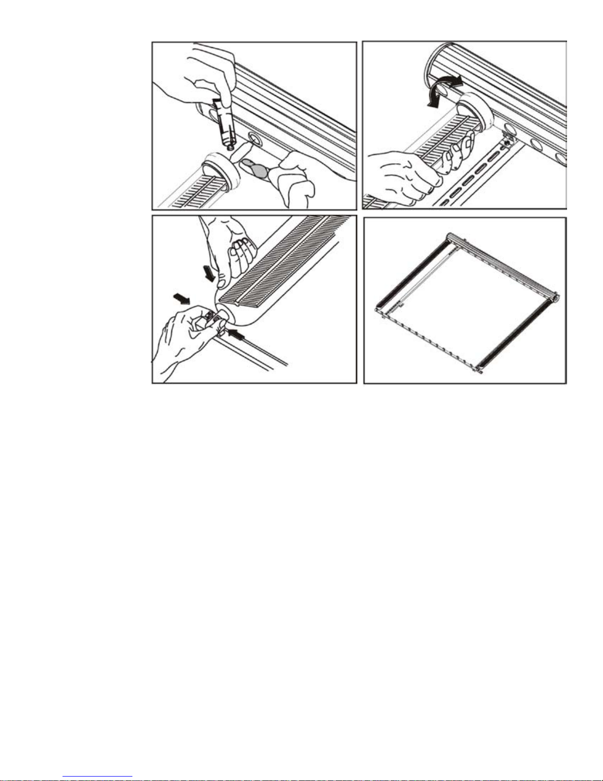
11
12
13
Installing the vacuum tubes
Grease condenser with heat transmission paste.
Note: Use a glove or a cloth to apply the paste.
Do not touch a hot condenser which could be as high
as 390 °F! Keep tubes covered before installation.
When tubes are exposed to the sun, the temperature of
the condenser could reach 390 °F or higher.
Align the tube and slide the condenser gently into the
manifold while turning the tube gently back and forth.
Adjust vacuum tube. Keep blue selective coating side
facing upward. The rubber gasket atop the vacuum tube
must be set within manifold hole in header to securely
seal heat pipe in manifold.
Put the end cap of the tube into the clip. If necessary,
adjust the location of the bottom support. The end of the
tube should rest on the rubber strip of the bottom support.
Close clip. Clip is sharp, use gloves to close clip.
32
Install one vacuum tube on either end, and check the
whole collector for square lines.
Install each vacuum tube from one end to the other.
082809
Page 34
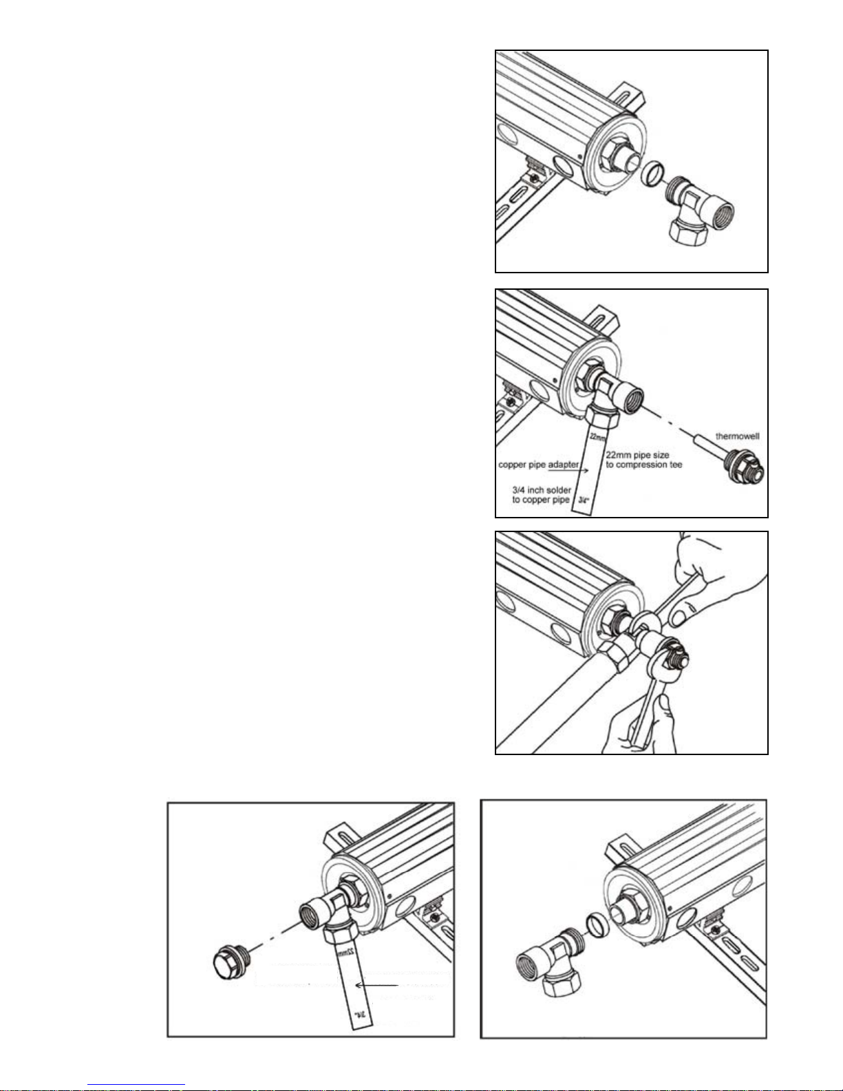
Connect Piping to the Manifold
With each roof mounting kit, there are adapters to pipe to
the manifold. Included are:
l Two compression tees to attach to the supply and
return terminations on each collector manifold or collector
array;
l Two copper pipe adapters that adapt from 22mm
copper pipe size (at compression tee) to 3/4” copper pipe.
Also included in some roof kits are two stainless steel
exible hoses and additional compression couplings for
copper pipe adapters.
NOTE: Use 1/2” copper supply and return for collectors
with up to 24 tubes (one 8- and one 16-tube collector)
and 3/4” copper for collectors with a 4- to 16-tube
collector array. Preferably use Type L. Do not use PEX
plastic tubing. PEX tubing cannot withstand
temperatures above 200°F and will fail.
Always insulate outdoor tubing with high temperature
Insultube and weather proong against UV degradation.
Use insulation with a wall thickness of at least 3/4”.
Install compression tees at supply and return on collector
manifold. Make sure the compression ring is well onto
the copper pipe terminating the manifold so that the
compression ring will not slide off the pipe as the
compression nut is tightened.
Install the Thermowell, which is for the collector sensor,
on the return outlet tee. Solder the threaded Thermowell
into the tee before installing the compression tee to the
header. Smear some heat transmission paste on the
sensor and insert the sensor into the Thermowell. Lock
sensor into place with set screw on the Thermowell.
Install the manual air vent on the manifold’s supply inlet
tee. If the piping rises above the collector on a closed
loop system, add an additional manual air vent at the
highest point of the loop.
Supply side
manual
air vent
22mm pipe size
to compression tee
082809
copper pipe adapter
3/4 inch solder to
copper pipe
33
Page 35
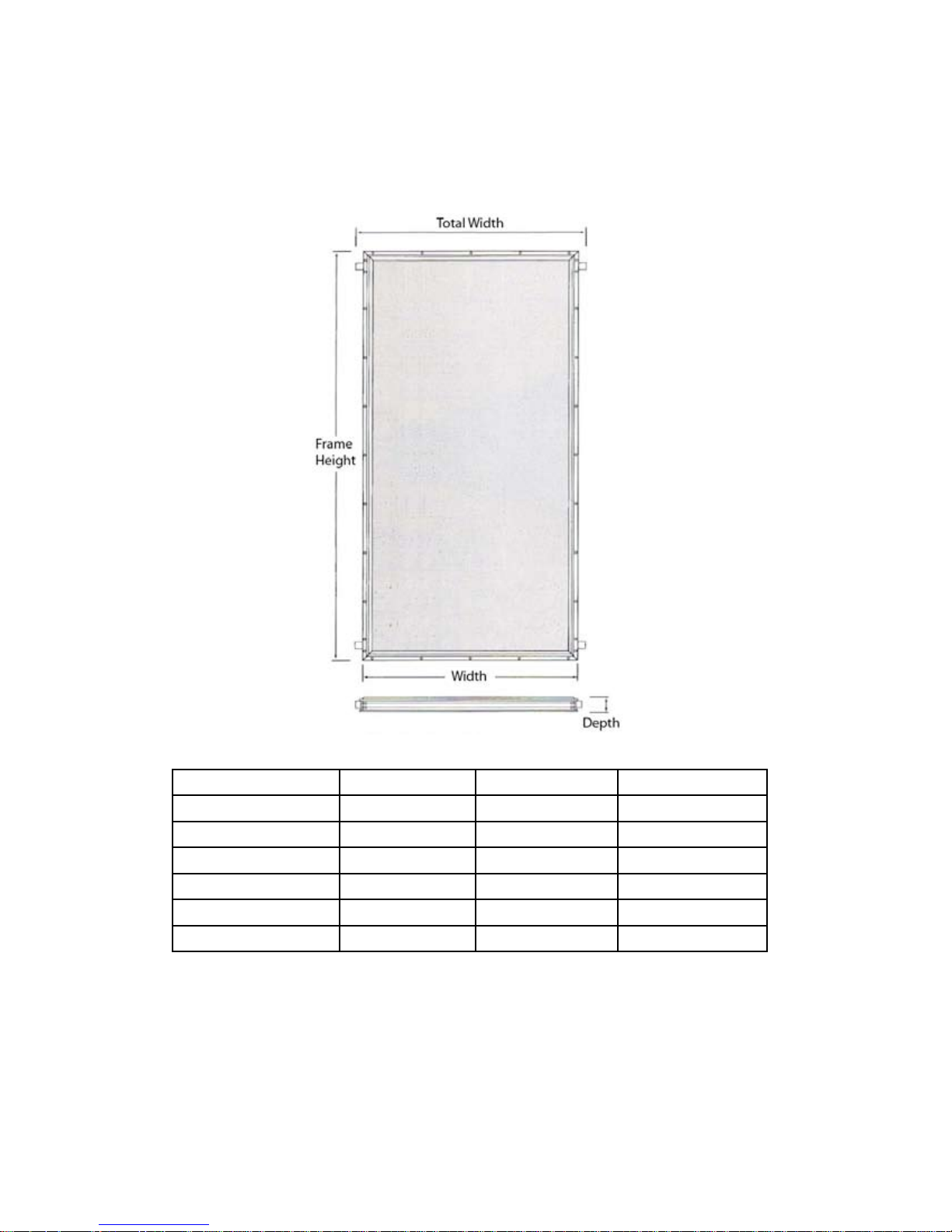
Section Seven
Oventrop Flat Plate solar thermal collector
(3’x7’ model OVF-21 - 540 03 07, 4’x8’ model OVF-32 - 540 04 08, 4’x10’ model - OVF-40 - 540 04 10)
Model (Part Number) 3’ x 7’ (540 03 07) 4’ x 8’ (540 04 08) 4’ x 10’ (540 04 10)
Gross Collector Area 21.5 sqft 32.7 sqft 40.7 sqft
Frame Height 86 inches 98 inches 122 inches
Frame Width 36 inches 48 inches 48 inches
Frame Depth 3-1/8 inches 3-1/8 inches 3-1/8 inches
Total Width 38 inches 50 inches 50 inches
Weight 76 lbs. 116 lbs. 151 lbs.
34
082809
Page 36
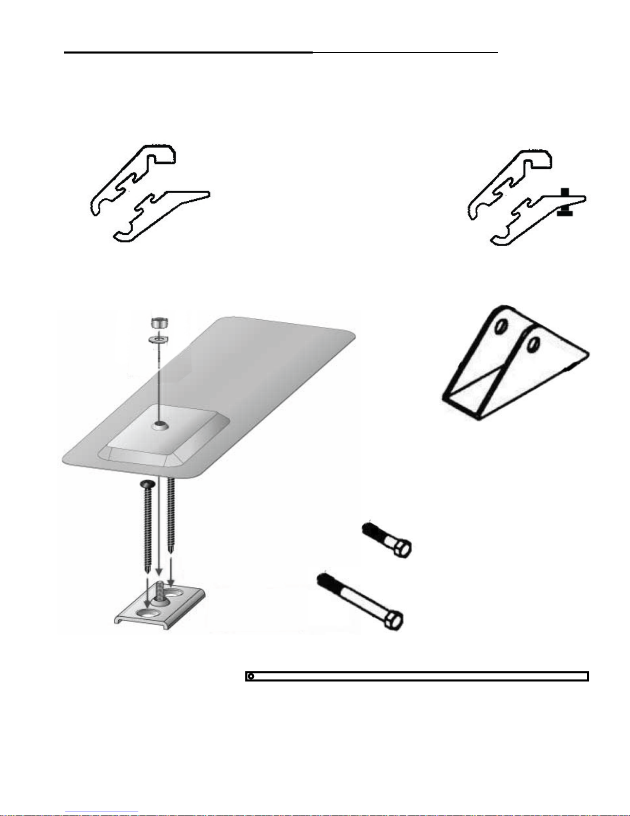
Adjustable Rack Mounting Kit for at plate collectors
540 00 28-FP
- for all at plate collectors (OVF-21, OVF-32, OVF-40)
Contents:
4 - Flat Plate Quick-Lock collector clamp
2 - Flat Plate Quick-Lock collector clamp
With locking screw
4 - Roof mounting ashing kits
4 - Triangle base bracket (foot)
4 - 2 inch bolt/washer/nut set
2 - 4 inch bolt/washer/nut set
2 - Aluminum square tube
Dimensions: 72L x 1.0W x 1.0H inches
082809
35
Page 37
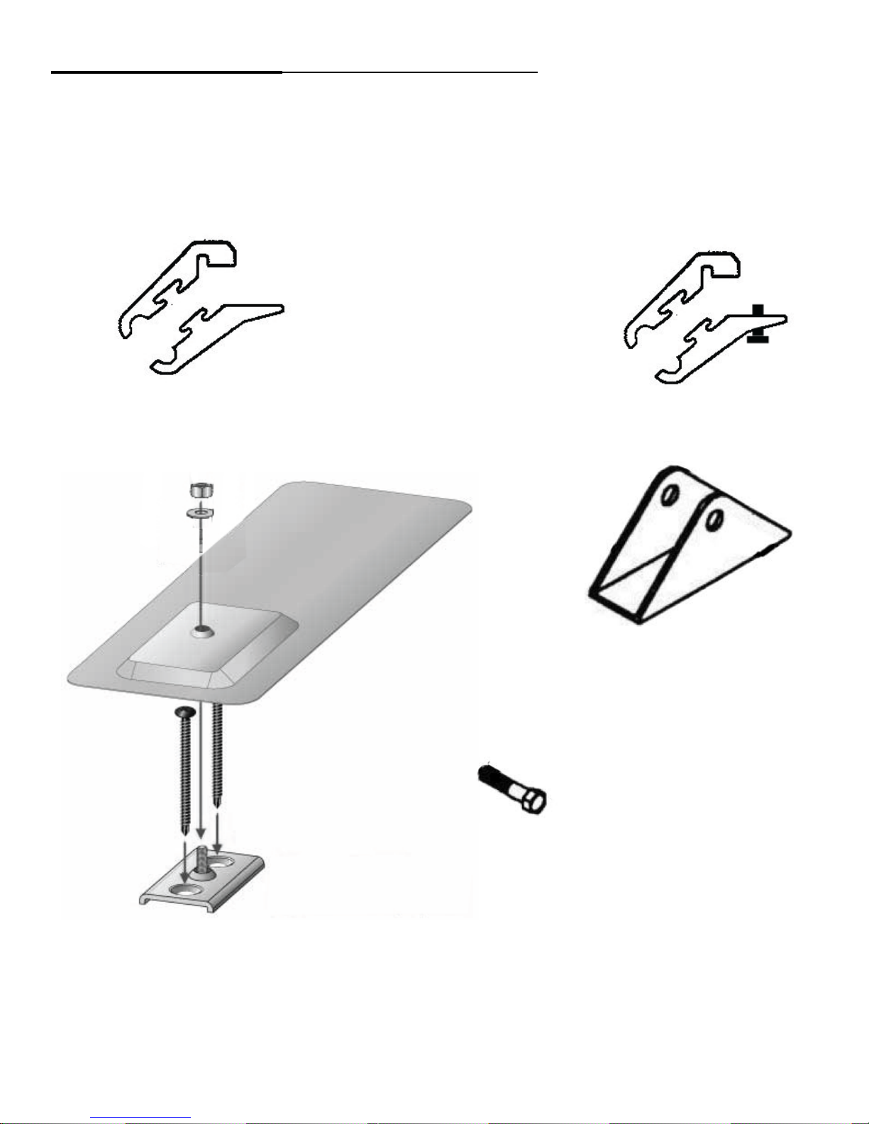
Flush Mounting Kit for at plate collectors
540 00 28-FPFM
- for all at plate collectors (OVF-21, OVF-32, OVF-40)
Contents:
2 - Flat Plate Quick-Lock collector clamp
2 - Flat Plate Quick-Lock collector clamp
With locking screw
4 - Roof mounting ashing kits
4 - Triangle base bracket (foot)
4 - 2 inch bolt/washer/nut set
36
082809
Page 38
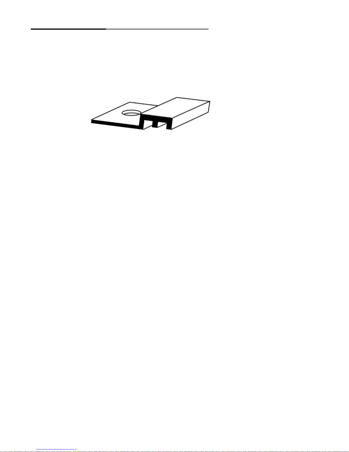
Strut Mount Clips for at plate collectors
540 00 28-FC
- for all at plate collectors (OVF-21, OVF-32, OVF-40)
Contents:
Set of 4 clips
These clips are used to attach and secure the at plate collectors to strut mounting channel assemblies.
Required but not provided are strut channel, strut locknuts, bolts and washers.
Strut clips are usually used to mount at plate collectors to horizontal bearing strut.
082809
37
Page 39
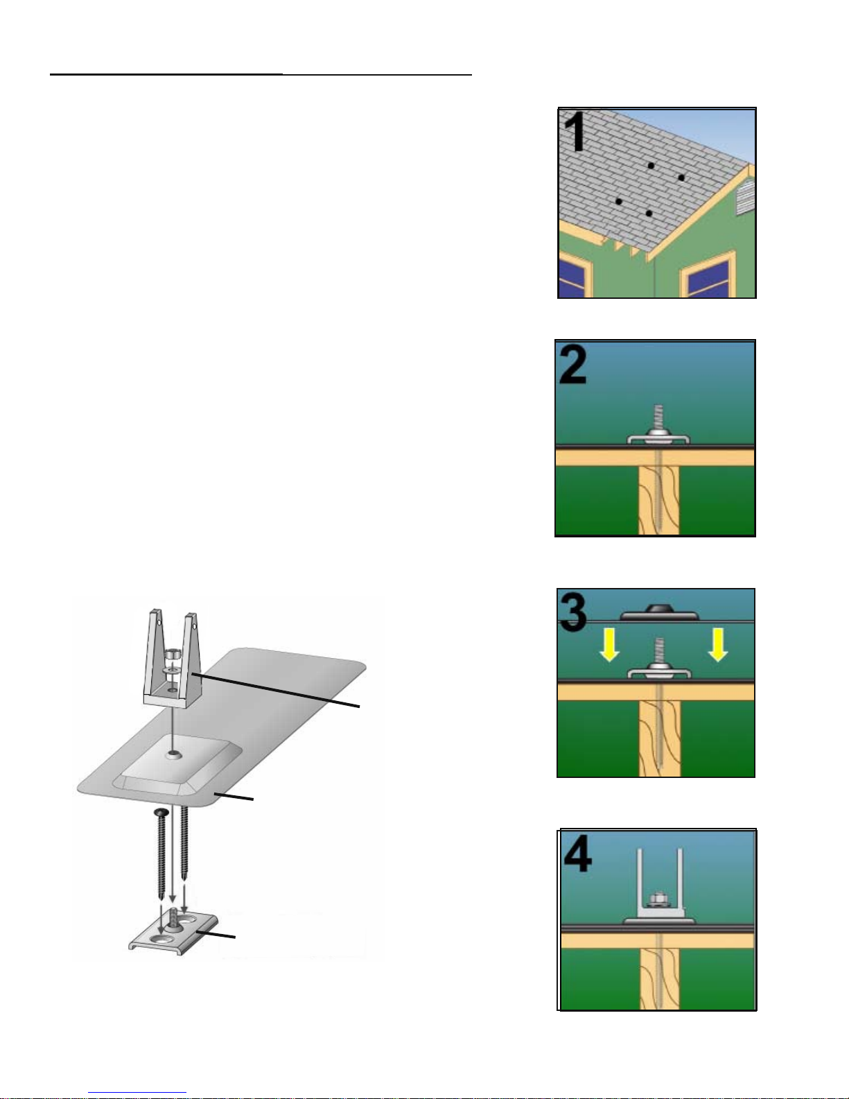
Adjustable Mounting Kit for at plate collectors 540 00 28-FP
- for all at plate collectors (OVF-21, OVF-32, OVF-40)
Installing the collector feet and ashing
COLLECTOR FOOT MUST BE ATTACHED TO THE BASE PLATE
USING THE CENTER HOLE.
No need to remove any shingles to install the ashing. Base plate is rst screwed
into roof rafter or block and ashing is slided under the roof shingle covering the
installed base plate.
Tools Required:
- Cordless drill with #2 square drive bits
- Tape measure, stud nder, chalk line
1. Locate the rafters and snap horizontal and vertical lines to mark the installa-
tion position for each mounting foot. Blocks, installed in the attic, may have to
be positioned between the rafters to make sure the base plate has a structural
member to screw into.
2. Install the base plate with the square drive screws. Mark the screw locations
and apply polyurethane sealant at the penetrations. The baseplate must be
securely attached atop the roof and into the roofs structural member.
3. Install ashing by sliding it into place under then next row of shingles. cover
base plate with the ashing pocket .
4. Install the collector foot as shown below using neoprene-bonded washer
and stainless locking nut. The collector foot must be tightened fully to restrict
unwanted movement.
Collector Feet
Flashing
Base Plate
Sealant must be applied to
any penetration of the roof
38
082809
Page 40
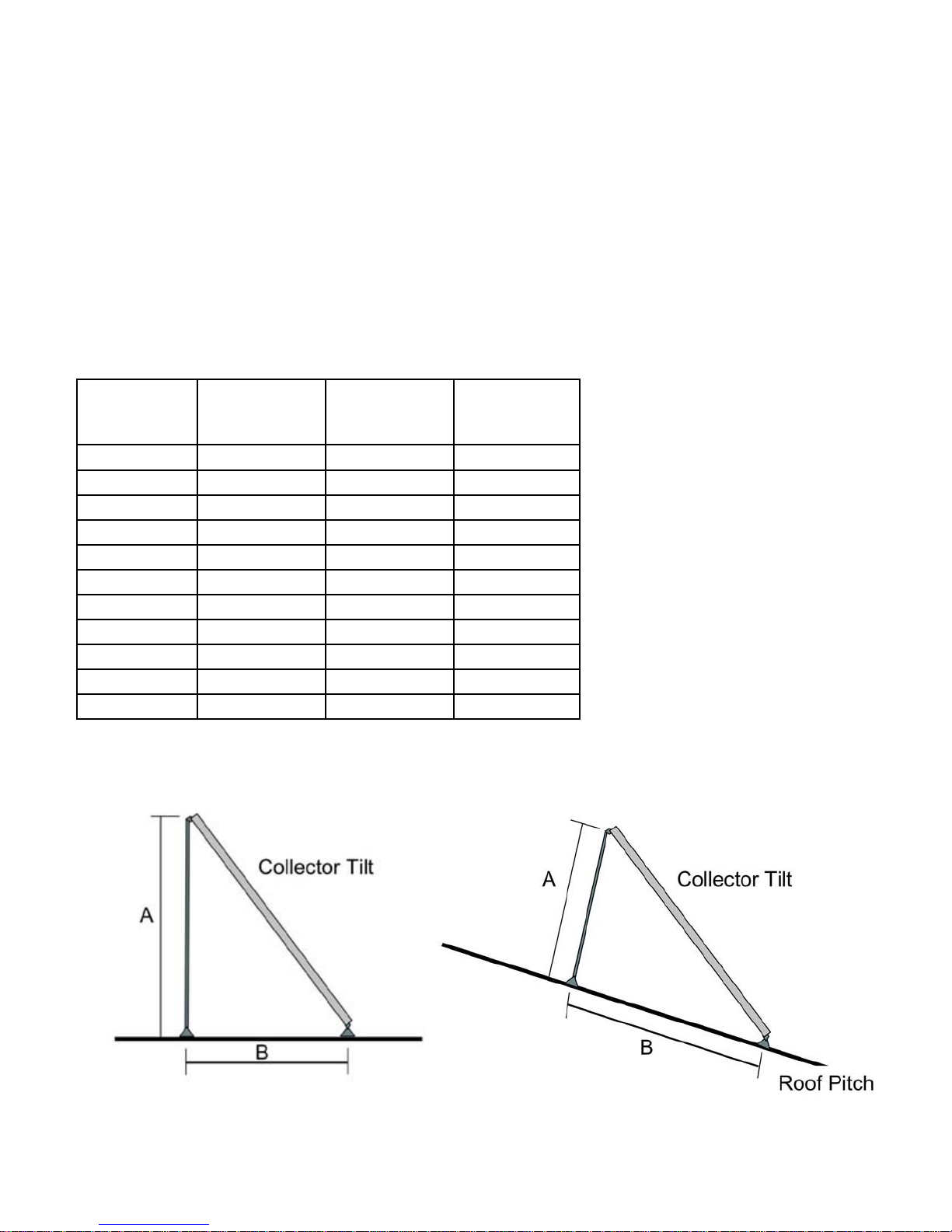
Measuring and cutting the rack legs
Use an angle nder tool to set the desired collector tilt angle during installation.
Table 1 below is to help you nd distances between the front and rear feet (B), and
the cut length for the rack leg (A) at various collector tilt angles.
The table is for collector tilt angle from a horizontal plane, such as for a at roof or
for ground mounting. (gure 1)
When mounting on a pitched roof (gure 2) the table can be used by subtracting the
roof pitch (angle) from the collector tilt angle to nd the remaining angle for Table 1.
With this method the collector legs will be perpendicular with the roof pitch (gure 2).
Table 1
Collector Tilt
Angle in degrees
from horizontal
A / B for OVF - 21
in inches
A / B for OVF - 32
in inches
5 8 / 86 9 / 98 11 / 122
10 15 / 85 17 / 97 21 / 120
15 22 / 83 25 / 95 32 / 118
20 30 / 81 34 / 92 42 / 115
25 36 / 78 42 / 89 52 / 111
30 43 / 74 49 / 85 61 / 105
35 49 / 71 56 / 80 70 / 100
40 55 / 66 63 / 75
45 61 / 61 69 / 69
50 66 / 55
55 71 / 49
A / B for OVF - 40
in inches
gure 1
082809
gure 2
39
Page 41
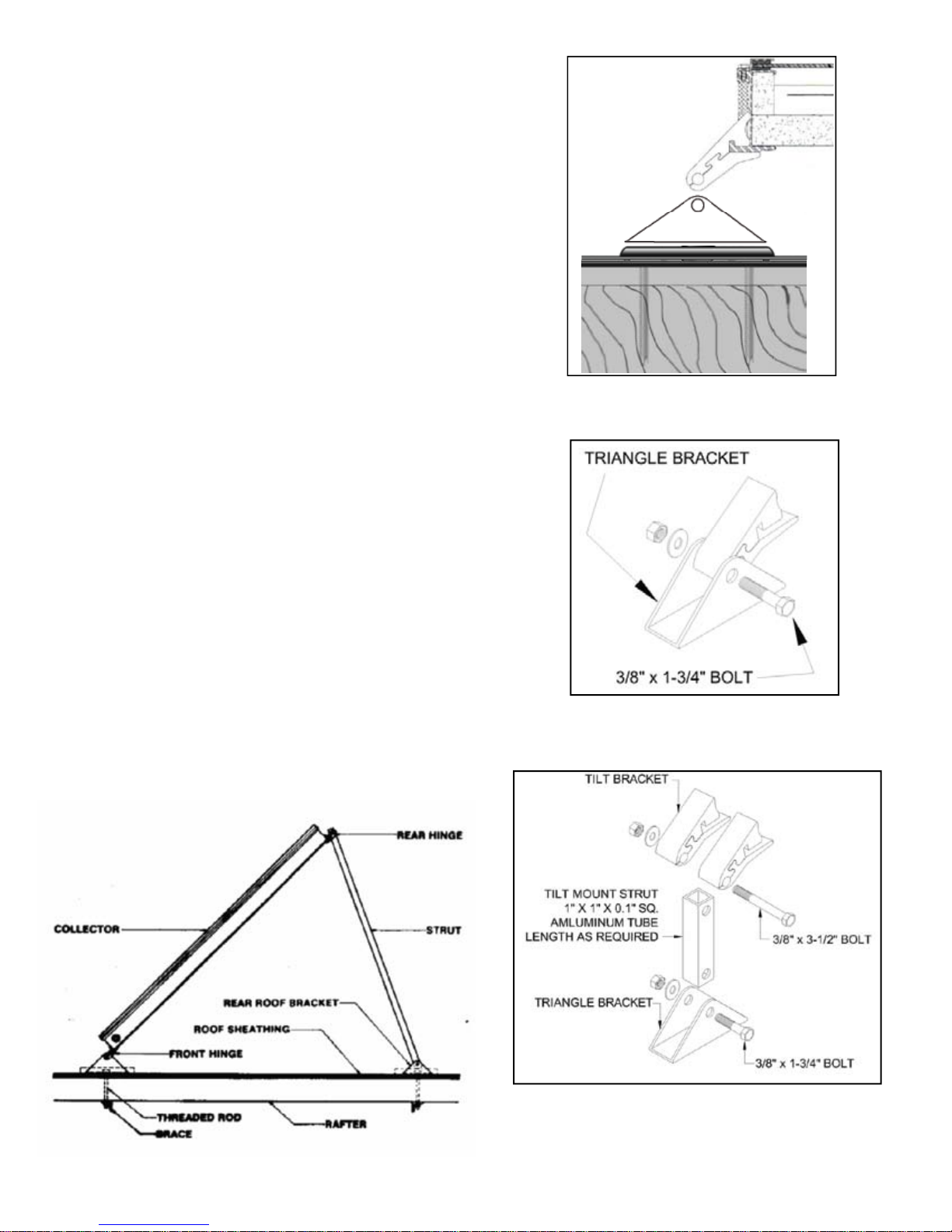
Mounting Hardware and Installation
The adjustable rack installation hardware is specially designed to speed
collector installation. This hardware consists of four Quick-Lock collector clamps for the rear top hinge, two Quick-Lock collector clamps with
locking screws for the front bottom hinge, four triangle brackets (collector
feet), two
aluminum square tube strut for collector legs, bolts, nuts and washers.
(See page 33).
After locating the mounting points for the collector feet, the base plate and
ashing should be installed (See page 38).
Install the triangle brackets on top of the ashing using the neoprene-
bonded washer and stainless locking nut.
The rear struts should be cut and drilled to the desired length from
Table 1.
Attach two Quick-Lock collector clamps with locking screws to
bottom of the collector. Keep the locking screws loose. Secure
the bottom Quick-Lock clamps on the collector and drop the
clamp into the triangle bracket using the bolt, washer, and nut
provided. Tighten locking screws after collector is set on the
triangle brackets. See diagram 1.
Attach the four Quick-Lock collector clamps to the top of the
collector. Using two Quick-Lock clamps per collector leg, bolt
the collector leg (mounting strut) to the top of the collector.
Attach both collector legs.
Raise the collector and bolt the bottom of the collector legs to
the collector foot with the bolt, washer, and nut provided.
See diagram 2.
Square up the collector legs and tighten all the nuts and bolts at
the collector feet and the rear collector hinge.
Quick-Lock collector clamp into front foot
front hinge Diagram 1
40
rear hinge and strut Diagram 2
082809
Page 42
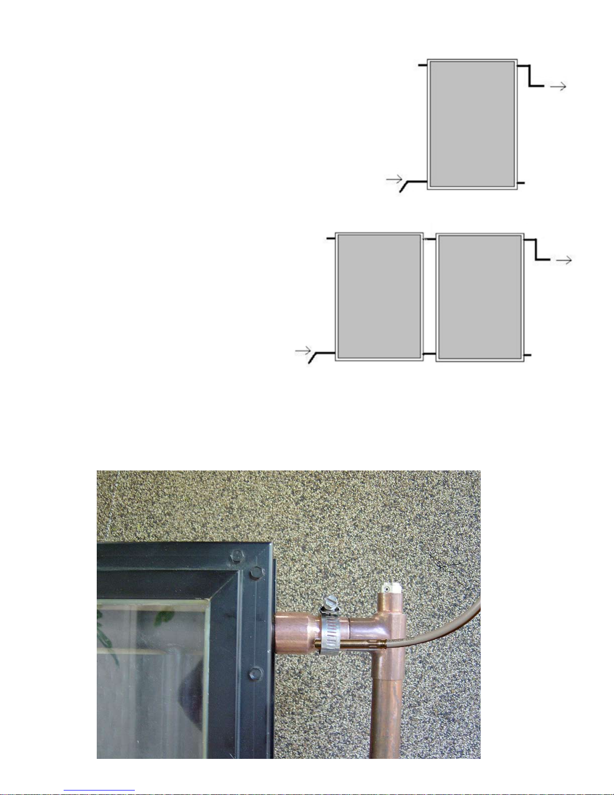
Flat Plate Collector Piping
The piping of the system should be considered before a nal decision is made
on how the collectors are mounted. Piping should be made of copper tube of
the type meeting local codes, insulated with Armaex or similar, and painted
or wrapped with aluminum tape where exposed to ultraviolet radiation.
Care should be taken in the spacing of collectors as attachment of piping
is easiest with properly aligned collectors. The collectors and piping to
the storage tank should be slightly sloped downward (3” in 8 feet) to allow
draining in case of freezing conditions. A manual air vent should be installed
at the top of the collector on the outlet. Soldered connections should be made
with 95/5 solder.
The outlets of the collector are 1” copper pipe nipples.
The copper union makes attachment of piping to collector
easy. Teon tape or high temperature, high quality pipe
sealant should be used when making threaded connections. The collector inlets should be piped similarly but
without the air vent.
Sensor Mounting at Collector
The controller heat sensor is mounted to the nipple
outlet of the collector (Figure 14). A stainless steel
screw clamp should be used. The entire nipple should
be wrapped thoroughly with insulating tape so that the
sensor is isolated from the outside air.
082809
41
Page 43
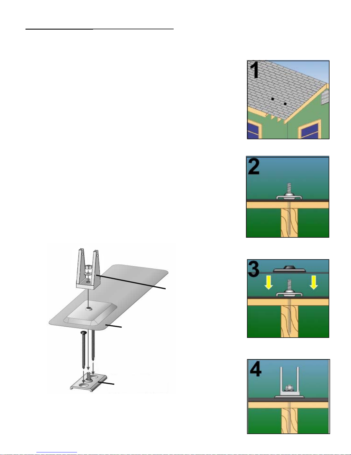
Flush Mounting Kit for at plate collectors 540 00 28-FPFM
- for all at plate collectors (OVF-21, OVF-32, OVF-40)
Installing the collector feet and ashing
COLLECTOR FOOT MUST BE ATTACHED TO THE BASE PLATE
USING THE CENTER HOLE.
No need to remove any shingles to install the ashing. Base plate is rst screwed
into roof rafter or block and ashing is slided under the roof shingle covering the
installed base plate.
Tools Required:
- Cordless drill with #2 square drive bits
- Tape measure, stud nder, chalk line
1. Locate the front feet locations on rafters and snap horizontal and vertical lines
to mark the installation position for each lower mounting foot. Blocks, installed in
the attic, may have to be positioned between the rafters to make sure the base
plate has a structural member to screw into.
2. Install the base plate with the square drive screws. Mark the screw locations
and apply polyurethane sealant at the penetrations. The baseplate must be
securely attached atop the roof and into the roofs structural member.
3. Install ashing by sliding it into place under then next row of shingles. Cover
the base plate with the ashing pocket .
4. Install the collector foot as shown below using neoprene-bonded washer
and stainless locking nut. The collector foot must be tightened fully to restrict
unwanted movement.
Collector Feet
set bottom feet rst then place
collector
Base Plate
Sealant must be applied to
any penetration of the roof
42
Flashing
082809
Page 44
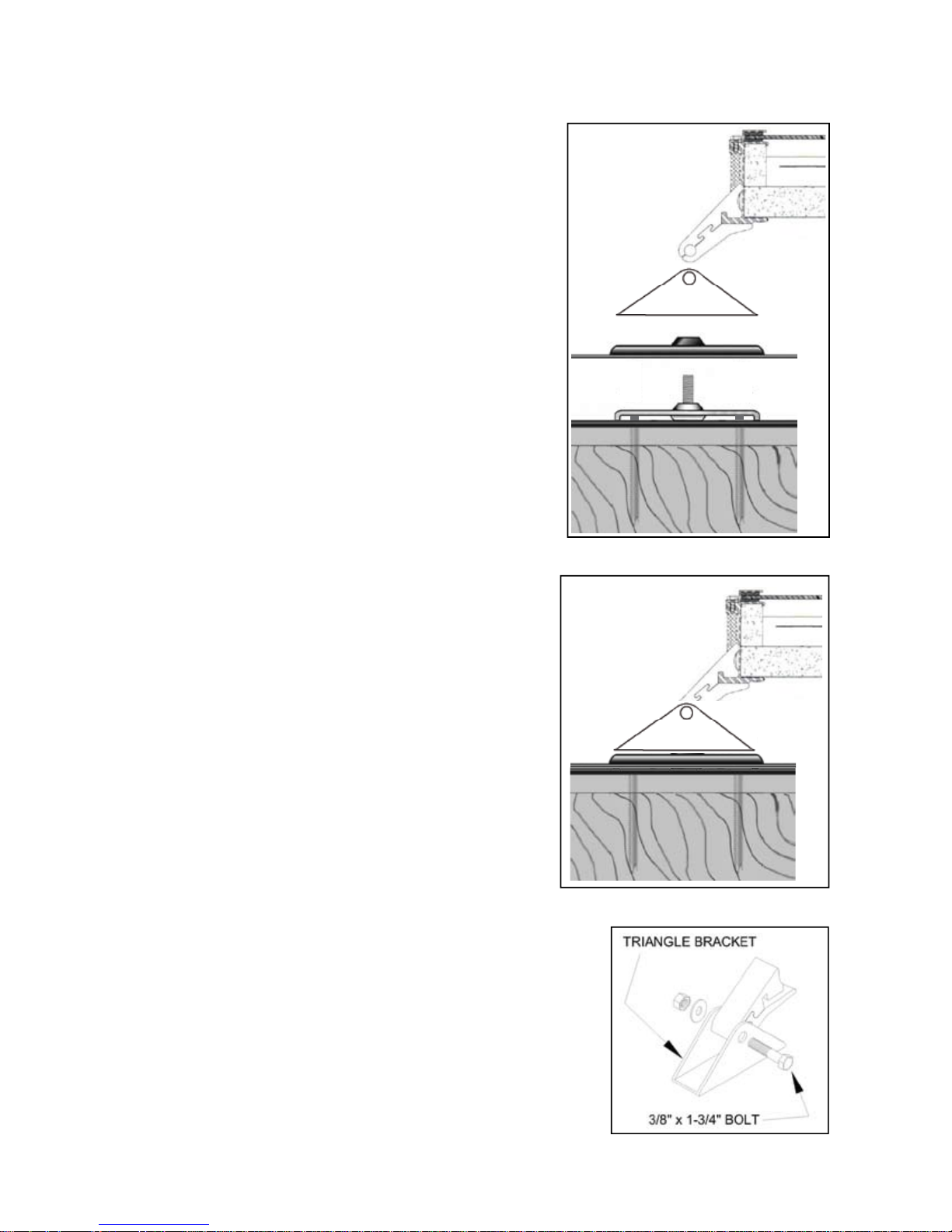
Flush Mounting Hardware and Installation
The ush mount installation hardware is specially designed to speed
collector installation. This hardware consists of two Quick-Lock collector clamps with locking screws for the front hinge, two Quick-Lock
collector clamps for the rear hinge, four triangle brackets (collector
feet), bolts, nuts and washers.
(See page 36).
Collector
Quick-Lock
Clamp
After installing the base plate and ashing, install the triangle brackets
on top of the ashing using the neoprene-bonded washer and stain-
less locking nut.
Next attach two Quick-Lock collector clamps with locking screws to
bottom of the collector. Keep the locking screws loose. Secure the
bottom Quick-Lock clamps on the collector and drop the clamp into
the triangle bracket using the bolt, washer, and nut provided. Tighten
locking screws after collector is set at position of location on the
triangle brackets. See diagram 1.
Attach the two upper Quick-Lock collector clamps to the collector
along with the two triangle brackets and roof mounting base plates.
Do not overtighten bolts.
Place the top of the collector down on the roof with the base plate
positioned over a rafter. Blocks, installed in the attic, may have to be
positioned between the rafters to make sure the base plate has a
structural member to screw into.
Draw the base plate layout onto the roof on the shingle.
Unbolt the base plate from the triangle bracket, and the triangle
bracket from the Quick-Lock.
Triangle
Bracket
Flashing
Base Plate
Square drive screws
Screw the baseplate onto it’s template on the shingle.
Install the base plate with the square drive screws. Mark the screw
locations and apply polyurethane sealant at the penetrations.
The baseplate must be securely attached atop the roof and into the
roofs structural member.
Install ashing by sliding it into place under then next row of shingles.
Cover the base plate with the ashing pocket .
Install the collector foot as shown below using neoprene-bonded
washer and stainless locking nut.
Attach the two Quick-Locks to the collector and bolt them into the
installed collector feet. Diagram 1.
Tighten all the nuts and bolts at the front and rear collector hinges.
082809
Front and rear hinge diagram 1
43
Page 45
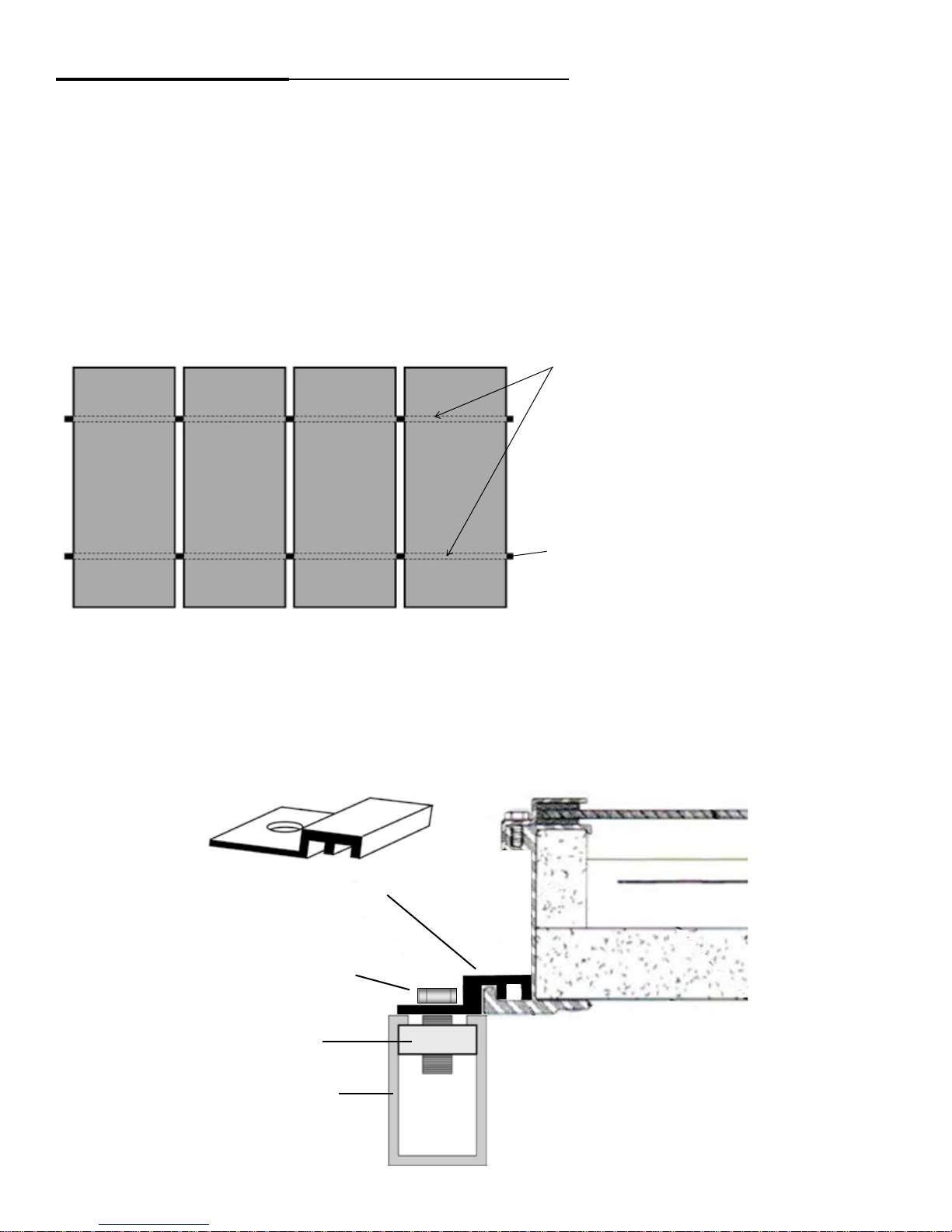
Strut Mount Clips for at plate collectors
540 00 28-FC
- for all at plate collectors (OVF-21, OVF-32, OVF-40)
Collector clips are designed to make Oventrop ate plate collectors
versitle enough to mount on strut channel assemblies, especially those
with locking strut nuts or locknuts.
Required but not provided are strut channel, strut locknuts, bolts and washers.
Usually the Collectors are attached and secured to two horizontal load bearing strut channels
placed 1 - 2 ft. in from the collector ends.
See gure below.
Strut Channel
Collectors
Collector Clip location
To connect the clips to the strut channel raise the collector onto the installed horizontal strut.
Attach the collector to the strut by using a collector clip, a bolt and a strut locknut.
Each collector has four mounting clips.
Collector
Collector Clip
Bolt
Locknut
Strut Channel
44
082809
Page 46
Section Eight
System Piping Schematics
The OVSOL System for solar energy described in this manual, when properly installed
and maintained, meets the minimum standards established by the SRCC.
This certication does not imply endorsement or warranty of this product by the SRCC.
Piping
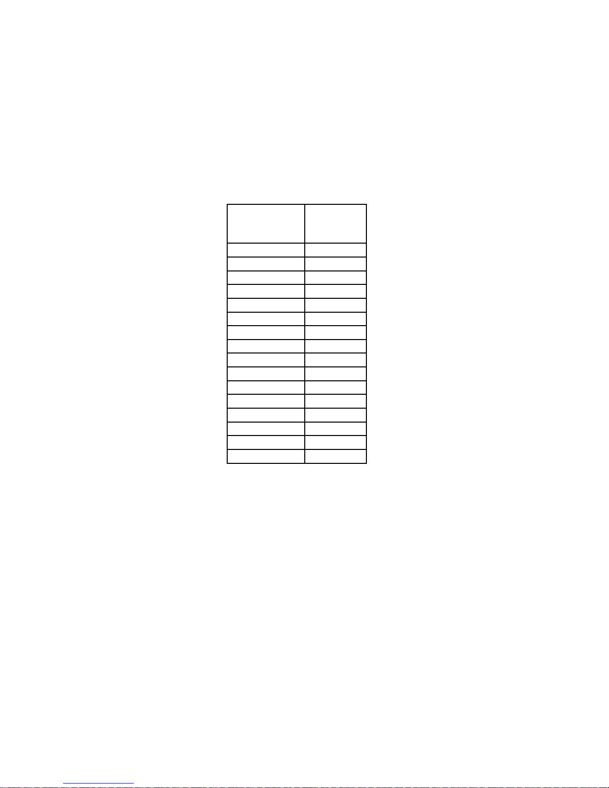
System Model
OVSOL 5-16-SC 46
OVSOL 5-16-SCE 47
OVSOL 5-16-DC 48
OVSOL 5-16-DCE 49
OVSOL 5-24-SC 50
OVSOL 5-24-SCE 51
OVSOL 5-24-DC 52
OVSOL 5-24-DCE 53
OVSOL FP-2-SC 54
OVSOL FP-2-SCE 55
OVSOL FP-2-DC 56
OVSOL FP-2-DCE 57
OVSOL FP-3-SC 58
OVSOL FP-3-SCE 59
OVSOL FP-3-DC 60
OVSOL FP-3-DCE 61
Schematic
page #
082809
45
Page 47
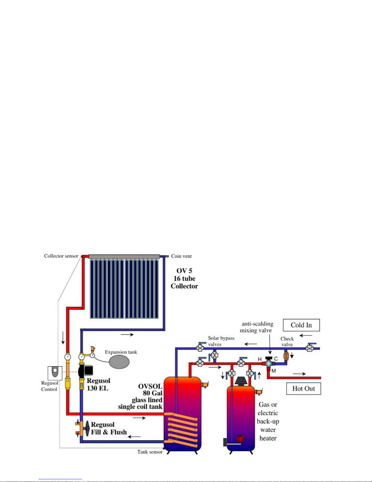
OVSOL System 5-16-SC / 80 gallon, Evacuated tube, Single coil tank
System Assembly
Installing OVSOL System 5-16-SC
Model Number 540 00 16K-SC
Solar Closed-Loop Domestic Hot Water System
Oventrop Components
OVSOL 5 -16 Evacuated Tube Collector . . . . . . . . . . . . . . . . . . . . . . . . . . . . . . . . . . lled weight: 225 lbs.
Regusol 130 EL Solar Transmission Station . . . . . . . . . . . . . . . . . . . . . . . . . . . . . . . lled weight: 20 lbs.
80 Gallon OVSOL glass lined Tank. . . . . . . . . . . . . . . . . . . . . . . . . . . . . . . . . . . lled weight: 940 lbs.
Regusol Fill and Flush Valve
Oventrop NT Propelyne Glycol Antifreeze
System Design Description
The solar closed-loop heating system consists of the Oventrop Regusol 130 EL pump and control station,
one OV-5 evacuated tube collector, and an 80 gallon glass lined tank with one internal coil. An expansion tank is
installed at the Regusol on the safety group. Oventrop NT propelyne glycol antifreeze is lled into the closed loop
system through the Regusol ll and ush valve.
Cold water is piped to the solar tank and in series with the back-up hot water heater. Solar bypass valves
are installed for servicing the solar tank. Back-up hot water heater bypass valves may be installed to bypass the hot
water heater. An anti-scald valve must be installed for hot water mixing to hot water xtures if the solar tank high
limit in the Regusol controller is set above 120
o
F.
46
082809
Page 48
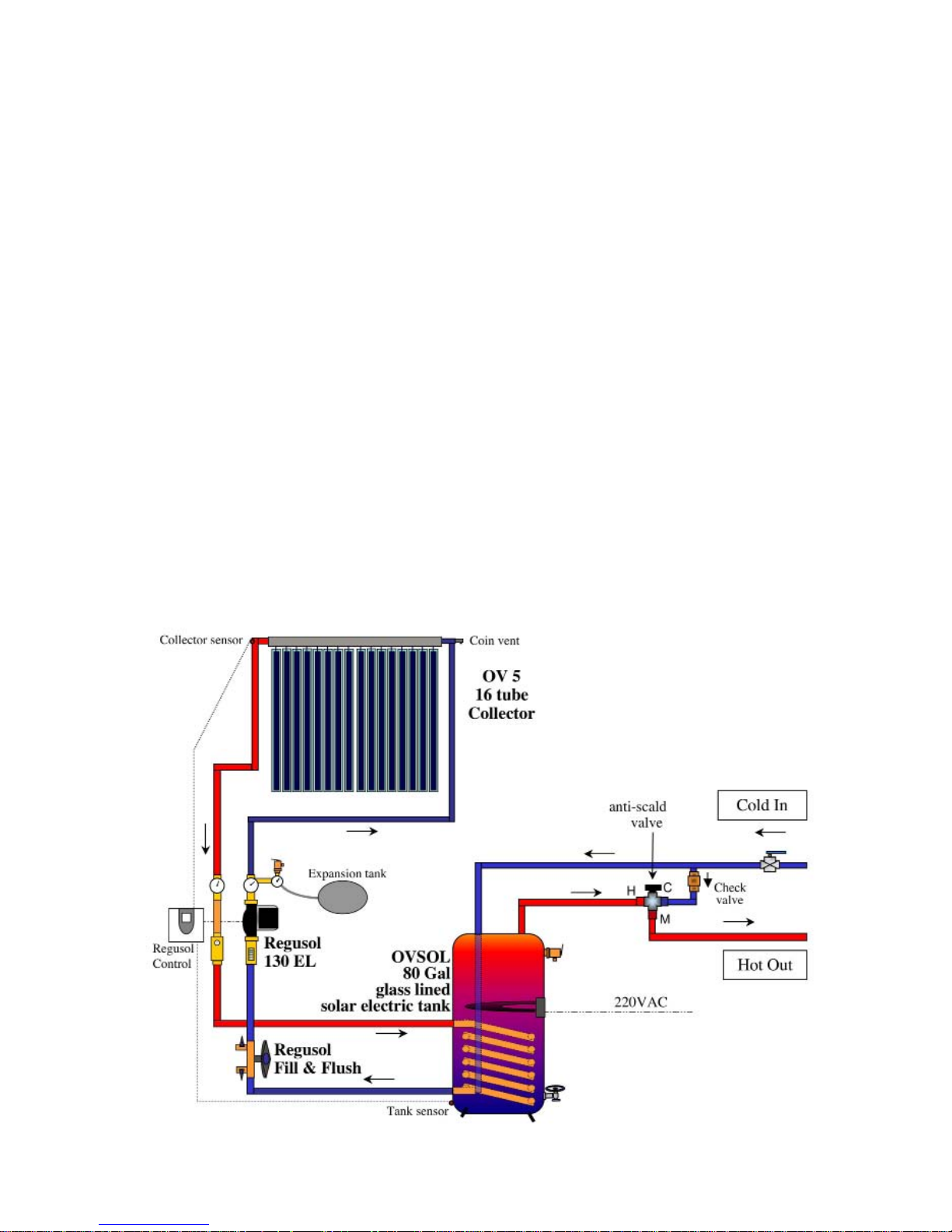
OVSOL System 5-16-SCE / 80 gallon, Evacuated tube, Single coil electric tank
System Assembly
Installing OVSOL System 5-16-SCE
Model Number 540 00 16K-SCE
Solar Closed-Loop Domestic Hot Water System
Oventrop Components
OVSOL 5 -16 Evacuated Tube Collector . . . . . . . . . . . . . . . . . . . . . . . . . . . . . . . . . . lled weight: 225 lbs.
Regusol 130 EL Solar Transmission Station . . . . . . . . . . . . . . . . . . . . . . . . . . . . . . . lled weight: 20 lbs.
80 Gallon OVSOL glass lined Tank. . . . . . . . . . . . . . . . . . . . . . . . . . . . . . . . . . . lled weight: 920 lbs.
Regusol Fill and Flush Valve
Oventrop NT Propelyne Glycol Antifreeze
System Design Description
The solar closed-loop heating system consists of the Oventrop Regusol 130 EL pump and control station,
one OV-5 evacuated tube collector, and an 80 gallon glass lined tank with one internal coil and electric backup element. An expansion tank is installed at the Regusol on the safety group. Oventrop NT propelyne glycol antifreeze is
lled into the closed loop system through the Regusol ll and ush valve.
Cold water is piped to the solar tank. An anti-scald valve must be installed for hot water mixing to hot water
xtures if the solar tank high limit in the Regusol controller is set above 120
o
F.
082809
47
Page 49
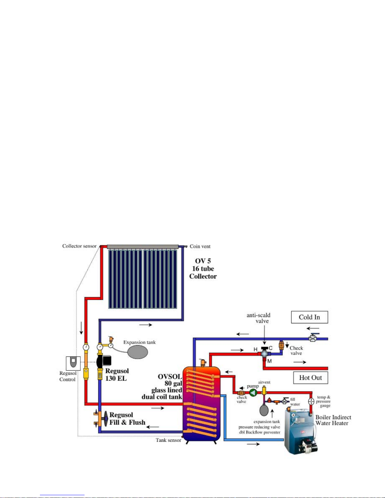
OVSOL System 5-16-DC / 80 gallon, Evacuated tube, Dual coil tank
System Assembly
Installing OVSOL System 5-16-DC
Model Number 540 00 16K-DC
Solar Closed-Loop Domestic Hot Water System
Oventrop Components
OVSOL 5 -16 Evacuated Tube Collector . . . . . . . . . . . . . . . . . . . . . . . . . . . . . . . . . . lled weight: 225 lbs.
Regusol 130 EL Solar Transmission Station . . . . . . . . . . . . . . . . . . . . . . . . . . . . . . . lled weight: 20 lbs.
80 Gallon OVSOL glass lined Tank. . . . . . . . . . . . . . . . . . . . . . . . . . . . . . . . . . . lled weight: 970 lbs.
Regusol Fill and Flush Valve
Oventrop NT Propelyne Glycol Antifreeze
System Design Description
The solar closed-loop heating system consists of the Oventrop Regusol 130 EL pump and control station,
one OV-5 evacuated tube collector, and an 80 gallon glass lined tank with two internal coils. An expansion tank is
installed at the Regusol on the safety group. Oventrop NT propylene glycol antifreeze is lled into the closed loop
system through the Regusol ll and ush valve.
Cold water is piped to the solar tank. An anti-scald valve must be installed for hot water mixing to hot water
xtures if the solar tank high limit in the Regusol controller is set above 120
the manner of a standard indirect water heater.
o
F. The top coil is piped to the boiler in
48
082809
Page 50
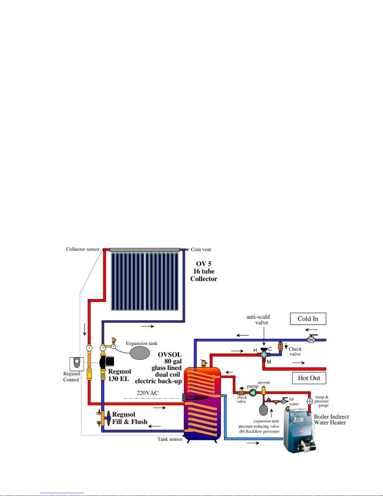
OVSOL System 5-16-DCE / 80 gallon, Evacuated tube, Dual coil electric tank
System Assembly
Installing OVSOL System 5-16-DCE
Model Number 540 00 16K-DCE
Solar Closed-Loop Domestic Hot Water System
Oventrop Components
OVSOL 5 -16 Evacuated Tube Collector . . . . . . . . . . . . . . . . . . . . . . . . . . . . . . . . . . lled weight: 225 lbs.
Regusol 130 EL Solar Transmission Station . . . . . . . . . . . . . . . . . . . . . . . . . . . . . . . lled weight: 20 lbs.
80 Gallon OVSOL glass lined Tank. . . . . . . . . . . . . . . . . . . . . . . . . . . . . . . . . . . lled weight: 970 lbs.
Regusol Fill and Flush Valve
Oventrop NT Propelyne Glycol Antifreeze
System Design Description
The solar closed-loop heating system consists of the Oventrop Regusol 130 EL pump and control station,
one OV-5 evacuated tube collector, and an 80 gallon glass lined tank with two internal coils and an electric backup
element. An expansion tank is installed at the Regusol on the safety group. Oventrop NT propylene glycol antifreeze
is lled into the closed loop system through the Regusol ll and ush valve.
Cold water is piped to the solar tank. An anti-scald valve must be installed for hot water mixing to hot water
xtures if the solar tank high limit in the Regusol controller is set above 120
the manner of a standard indirect water heater.
o
F. The top coil is piped to the boiler in
082809
49
Page 51
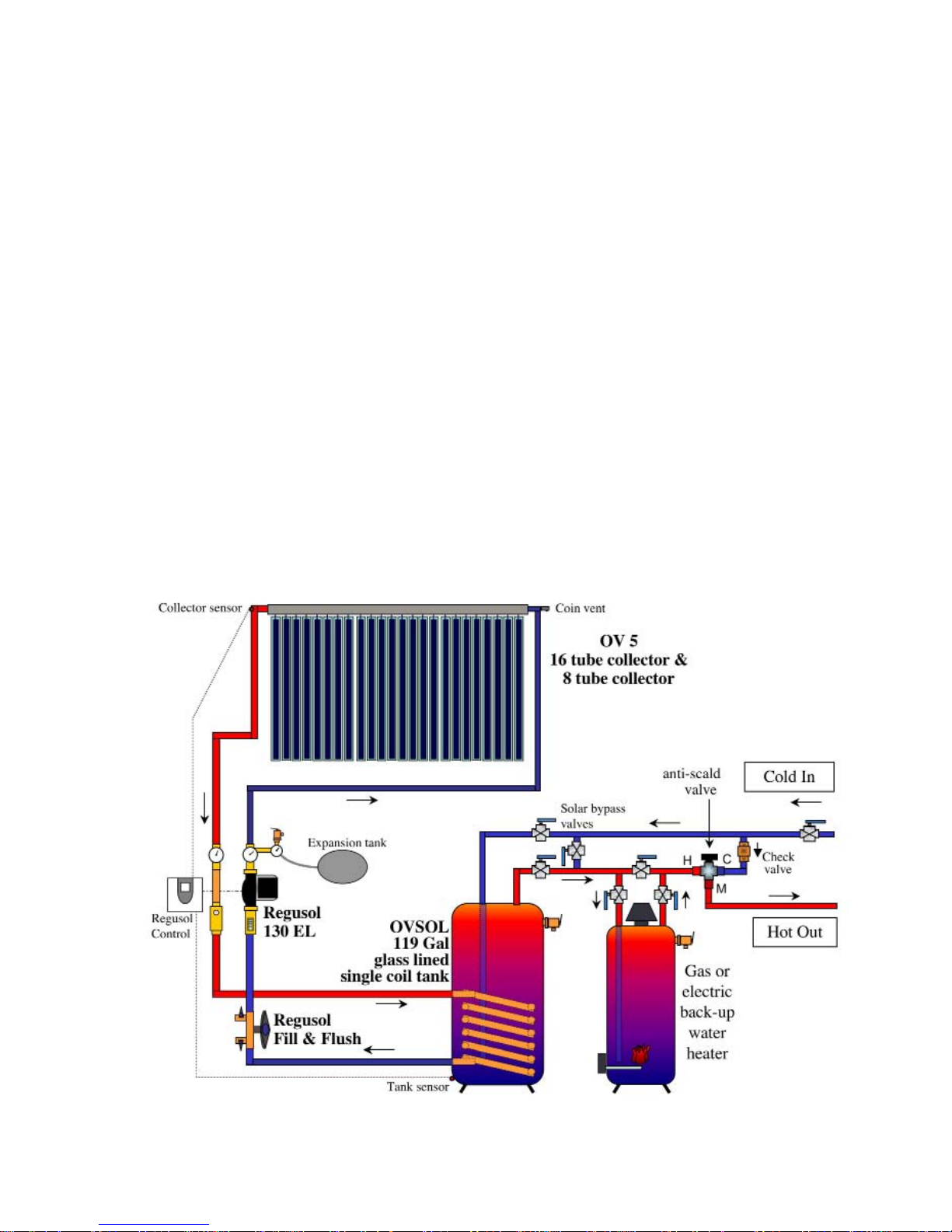
OVSOL System 5-24-SC / 119 gallon, Evacuated tube, Single coil tank
System Assembly
Installing OVSOL System 5-24-SC
Model Number 540 00 17K-SC
Solar Closed-Loop Domestic Hot Water System
Oventrop Components
OVSOL 5 -16 and 5-8 Evacuated Tube Collector . . . . . . . . . . . . . . . . . . . . . . . . . . . lled weight: 337 lbs.
Regusol 130 EL Solar Transmission Station . . . . . . . . . . . . . . . . . . . . . . . . . . . . . . . lled weight: 20 lbs.
119 Gallon OVSOL glass lined Tank. . . . . . . . . . . . . . . . . . . . . . . . . . . . . . . . . . . lled weight:1315 lbs.
Regusol Fill and Flush Valve
Oventrop NT Propelyne Glycol Antifreeze
System Design Description
The solar closed-loop heating system consists of the Oventrop Regusol 130 EL pump and control station,
one OV-5 evacuated tube collector, and an 80 gallon glass lined tank with one internal coil. An expansion tank is
installed at the Regusol on the safety group. Oventrop NT propelyne glycol antifreeze is lled into the closed loop
system through the Regusol ll and ush valve.
Cold water is piped to the solar tank and in series with the back-up hot water heater. Solar bypass valves
are installed for servicing the solar tank. Back-up hot water heater bypass valves may be installed to bypass the hot
water heater. An anti-scald valve must be installed for hot water mixing to hot water xtures if the solar tank high
limit in the Regusol controller is set above 120
o
F.
50
082809
Page 52
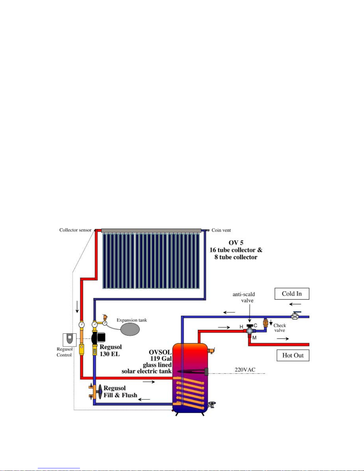
OVSOL System 5-24-SCE / 119 gallon, Evacuated tube, Single coil electric tank
System Assembly
Installing OVSOL System 5-24-SCE
Model Number 540 00 17K-SCE
Solar Closed-Loop Domestic Hot Water System
Oventrop Components
OVSOL 5 -16 and 5-8 Evacuated Tube Collector . . . . . . . . . . . . . . . . . . . . . . . . . . . lled weight: 337 lbs.
Regusol 130 EL Solar Transmission Station . . . . . . . . . . . . . . . . . . . . . . . . . . . . . . . lled weight: 20 lbs.
119 Gallon OVSOL glass lined Tank. . . . . . . . . . . . . . . . . . . . . . . . . . . . . . . . . . . lled weight: 1315 lbs.
Regusol Fill and Flush Valve
Oventrop NT Propelyne Glycol Antifreeze
System Design Description
The solar closed-loop heating system consists of the Oventrop Regusol 130 EL pump and control station,
one OV-5 evacuated tube collector, and an 80 gallon glass lined tank with one internal coil and an electric backup
element. An expansion tank is installed at the Regusol on the safety group. Oventrop NT propelyne glycol antifreeze
is lled into the closed loop system through the Regusol ll and ush valve.
Cold water is piped to the solar tank. An anti-scald valve must be installed for hot water mixing to hot water
xtures if the solar tank high limit in the Regusol controller is set above 120
o
F.
082809
51
Page 53
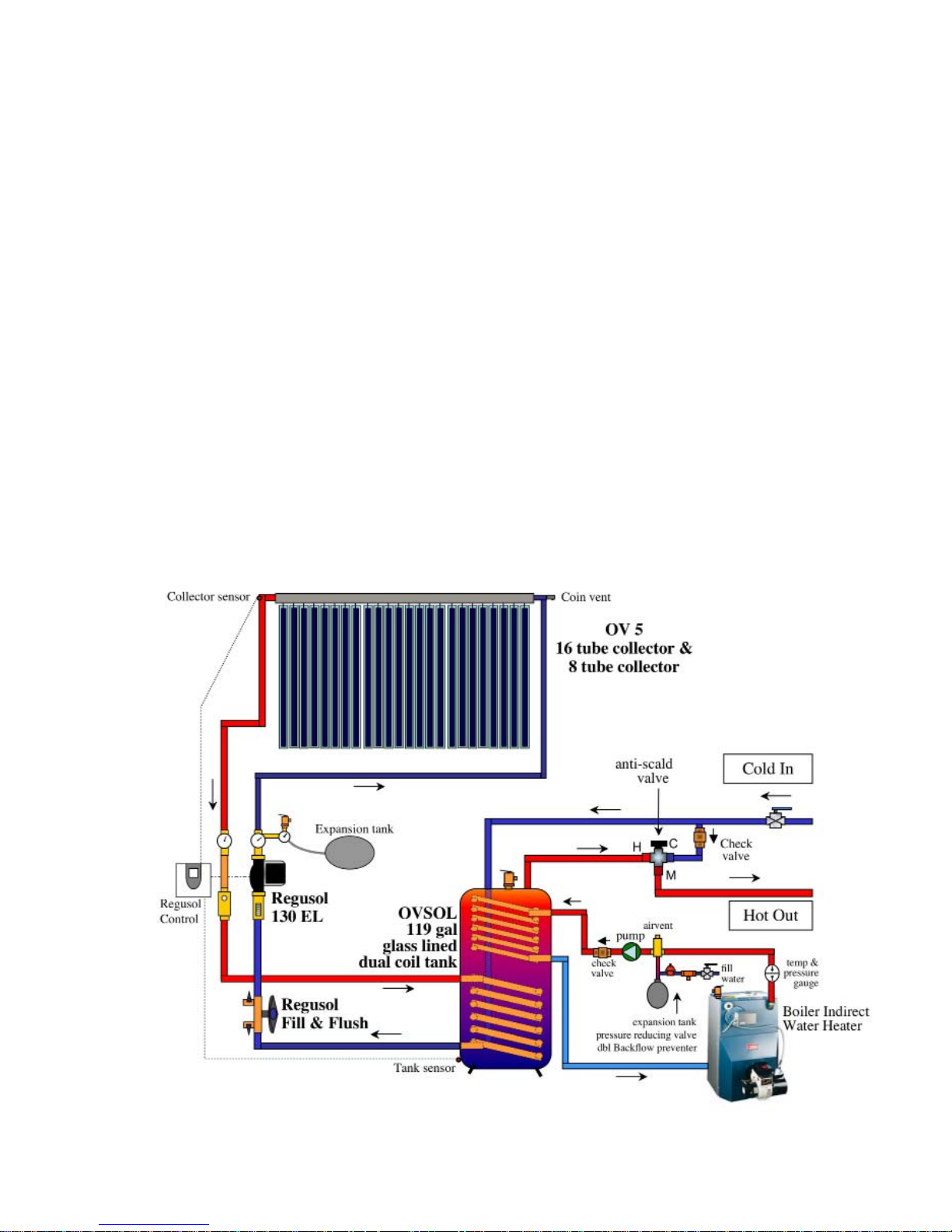
OVSOL System 5-24-DC / 119 gallon, Evacuated tube, Dual coil tank
System Assembly
Installing OVSOL System 5-24-DC
Model Number 540 00 17K-DC
Solar Closed-Loop Domestic Hot Water System
Oventrop Components
OVSOL 5 -16 and 5-8 Evacuated Tube Collector . . . . . . . . . . . . . . . . . . . . . . . . . . . lled weight: 337 lbs.
Regusol 130 EL Solar Transmission Station . . . . . . . . . . . . . . . . . . . . . . . . . . . . . . . lled weight: 20 lbs.
119 Gallon OVSOL glass lined Tank. . . . . . . . . . . . . . . . . . . . . . . . . . . . . . . . . . . lled weight: 1340 lbs.
Regusol Fill and Flush Valve
Oventrop NT Propelyne Glycol Antifreeze
System Design Description
The solar closed-loop heating system consists of the Oventrop Regusol 130 EL pump and control station,
one OV-5 evacuated tube collector, and an 80 gallon glass lined tank with two internal coils. An expansion tank is
installed at the Regusol on the safety group. Oventrop NT propelyne glycol antifreeze is lled into the closed loop
system through the Regusol ll and ush valve.
Cold water is piped to the solar tank. An anti-scald valve must be installed for hot water mixing to hot water
xtures if the solar tank high limit in the Regusol controller is set above 120
the manner of a standard indirect water heater.
o
F. The top coil is piped to the boiler in
52
082809
Page 54
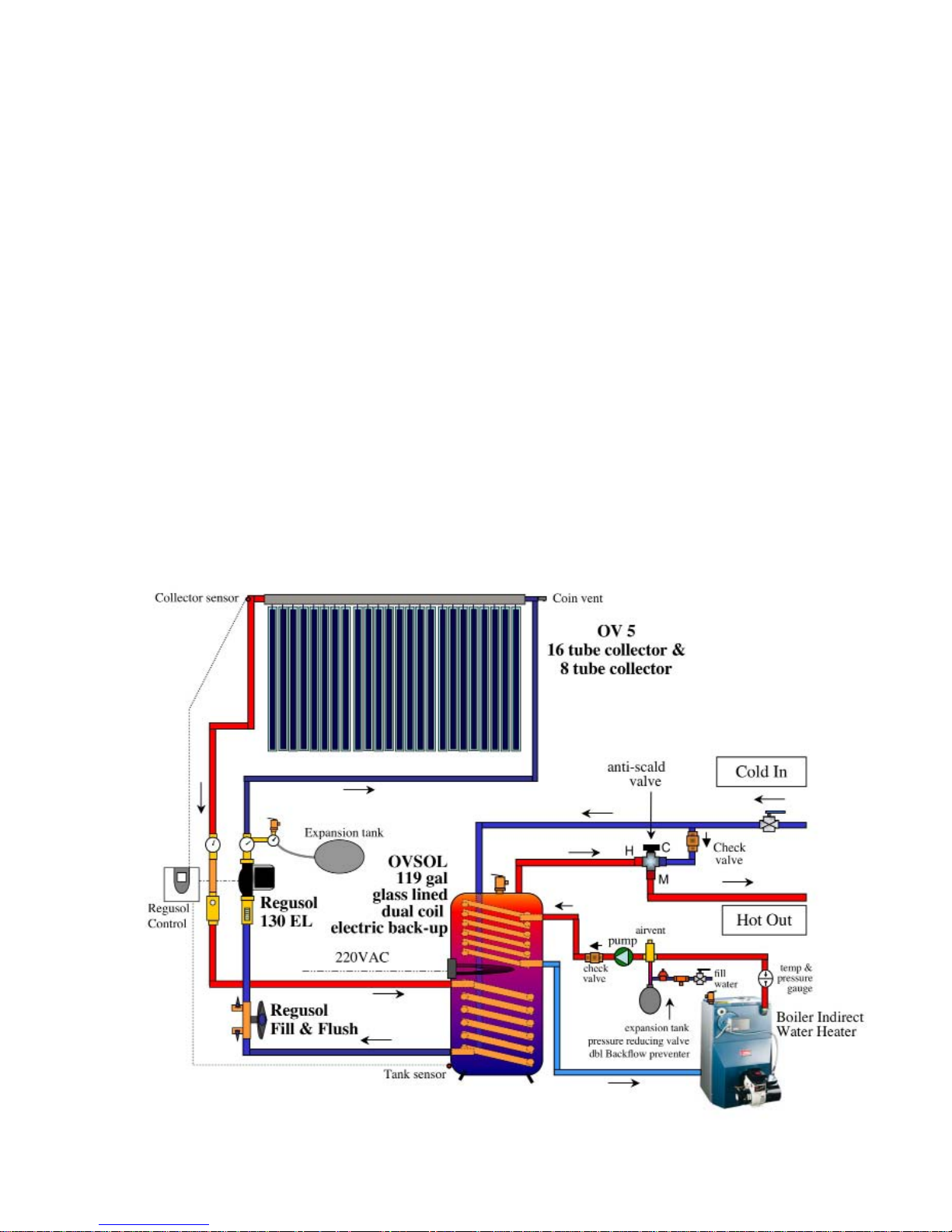
OVSOL System 5-24-DCE / 119 gallon, Evacuated tube, Dual coil electric tank
System Assembly
Installing OVSOL System 5-24-DCE
Model Number 540 00 17K-DCE
Solar Closed-Loop Domestic Hot Water System
Oventrop Components
OVSOL 5 -16 and 5-8 Evacuated Tube Collector . . . . . . . . . . . . . . . . . . . . . . . . . . . lled weight: 337 lbs.
Regusol 130 EL Solar Transmission Station . . . . . . . . . . . . . . . . . . . . . . . . . . . . . . . lled weight: 20 lbs.
119 Gallon OVSOL glass lined Tank. . . . . . . . . . . . . . . . . . . . . . . . . . . . . . . . . . . lled weight: 1340 lbs.
Regusol Fill and Flush Valve
Oventrop NT Propelyne Glycol Antifreeze
System Design Description
The solar closed-loop heating system consists of the Oventrop Regusol 130 EL pump and control station,
one OV-5 evacuated tube collector, and an 80 gallon glass lined tank with two internal coils and an electric backup
element. An expansion tank is installed at the Regusol on the safety group. Oventrop NT propelyne glycol antifreeze
is lled into the closed loop system through the Regusol ll and ush valve.
Cold water is piped to the solar tank. An anti-scald valve must be installed for hot water mixing to hot water
xtures if the solar tank high limit in the Regusol controller is set above 120
the manner of a standard indirect water heater.
o
F. The top coil is piped to the boiler in
082809
53
Page 55
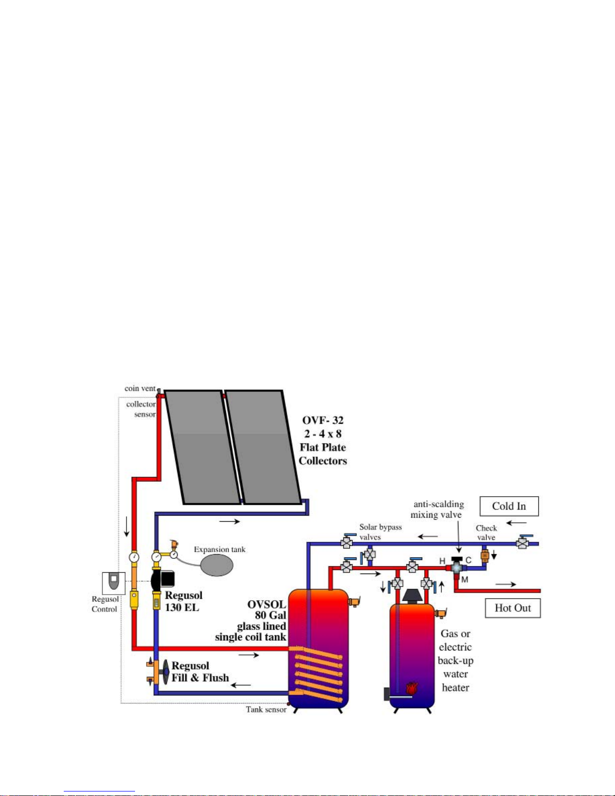
OVSOL System FP-2-SC / 80 gallon, Flat plate, Single coil tank
System Assembly
Installing OVSOL System FP-2-SC
Model Number 540 04 08K-SC
Solar Closed-Loop Domestic Hot Water System
Oventrop Components
Two OVF-32 Flat Plate Solar Collectors . . . . . . . . . . . . . . . . . . . . . . . . . . . . . . . . . . lled weight: 550 lbs.
Regusol 130 EL Solar Transmission Station . . . . . . . . . . . . . . . . . . . . . . . . . . . . . . . lled weight: 20 lbs.
80 Gallon OVSOL glass lined Tank. . . . . . . . . . . . . . . . . . . . . . . . . . . . . . . . . . . lled weight: 920 lbs.
Regusol Fill and Flush Valve
Oventrop NT Propelyne Glycol Antifreeze
System Design Description
The solar closed-loop heating system consists of the Oventrop Regusol 130 EL pump and control station,
one OV-5 evacuated tube collector, and an 80 gallon glass lined tank with one internal coil. An expansion tank is
installed at the Regusol on the safety group. Oventrop NT propelyne glycol antifreeze is lled into the closed loop
system through the Regusol ll and ush valve.
Cold water is piped to the solar tank and in series with the back-up hot water heater. Solar bypass valves
are installed for servicing the solar tank. Back-up hot water heater bypass valves may be installed to bypass the hot
water heater. An anti-scald valve must be installed for hot water mixing to hot water xtures if the solar tank high
limit in the Regusol controller is set above 120
o
F.
54
082809
Page 56
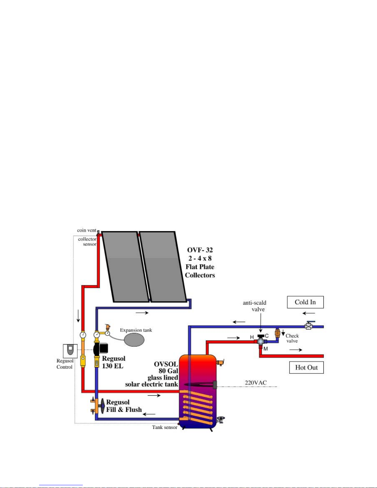
OVSOL System FP-2-SCE / 80 gallon, Flat plate, Single coil electric tank
System Assembly
Installing OVSOL System FP-2-SCE
Model Number 540 04 08K-SCE
Solar Closed-Loop Domestic Hot Water System
Oventrop Components
Two OVF-32 Flat Plate Solar Collectors . . . . . . . . . . . . . . . . . . . . . . . . . . . . . . . . . . lled weight: 550 lbs.
Regusol 130 EL Solar Transmission Station . . . . . . . . . . . . . . . . . . . . . . . . . . . . . . . lled weight: 20 lbs.
80 Gallon OVSOL glass lined Tank. . . . . . . . . . . . . . . . . . . . . . . . . . . . . . . . . . . lled weight: 920 lbs.
Regusol Fill and Flush Valve
Oventrop NT Propelyne Glycol Antifreeze
System Design Description
The solar closed-loop heating system consists of the Oventrop Regusol 130 EL pump and control station,
one OV-5 evacuated tube collector, and an 80 gallon glass lined tank with one internal coil and an electric backup
element. An expansion tank is installed at the Regusol on the safety group. Oventrop NT propelyne glycol antifreeze
is lled into the closed loop system through the Regusol ll and ush valve.
Cold water is piped to the solar tank. An anti-scald valve must be installed for hot water mixing to hot water
xtures if the solar tank high limit in the Regusol controller is set above 120
o
F.
082809
55
Page 57
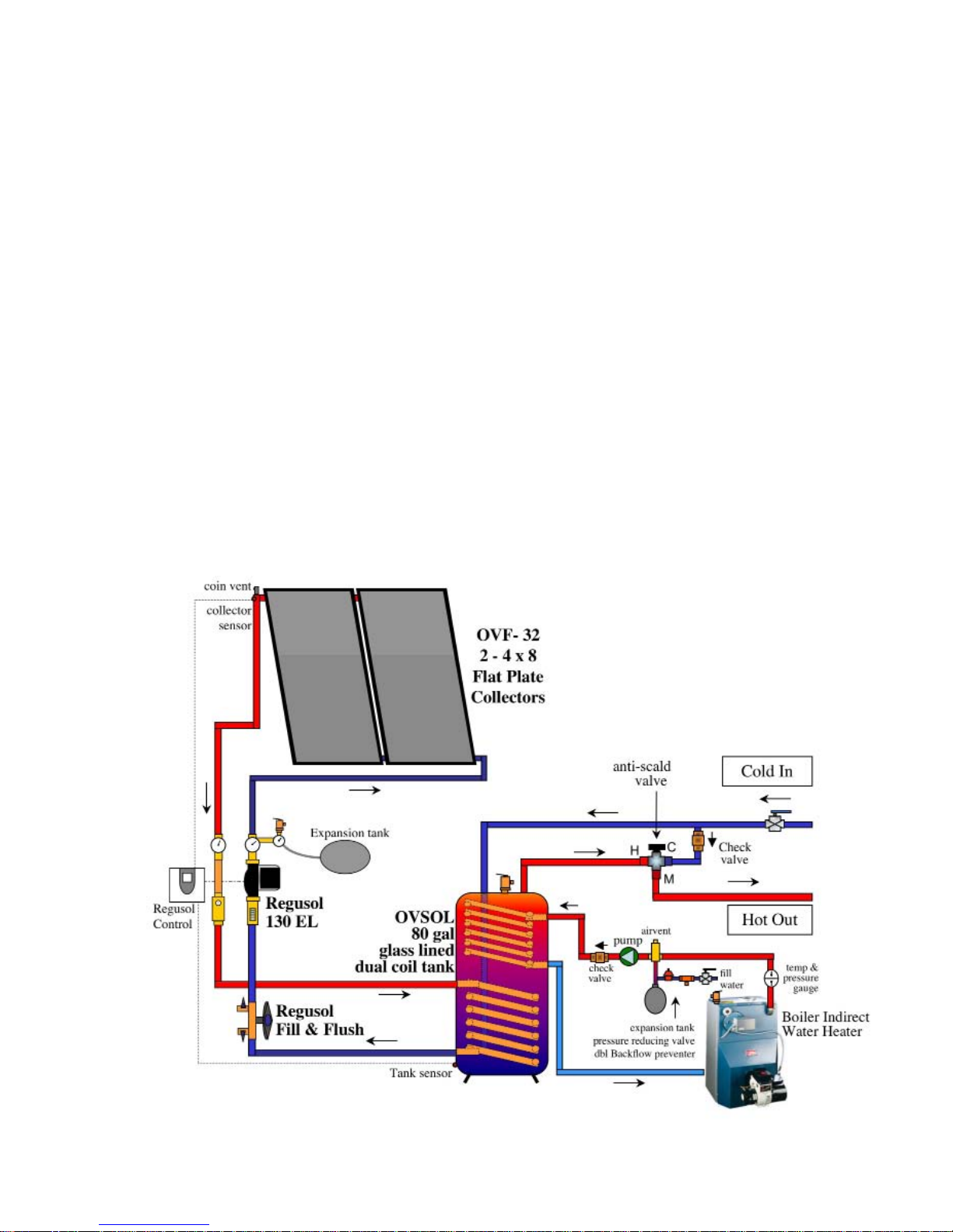
OVSOL System FP-2-DC / 80 gallon, Flat plate, Dual coil tank
System Assembly
Installing OVSOL System FP-2-DC
Model Number 540 04 08K-DC
Solar Closed-Loop Domestic Hot Water System
Oventrop Components
Two OVF-32 Flat Plate Solar Collectors . . . . . . . . . . . . . . . . . . . . . . . . . . . . . . . . . . lled weight: 550 lbs.
Regusol 130 EL Solar Transmission Station . . . . . . . . . . . . . . . . . . . . . . . . . . . . . . . lled weight: 20 lbs.
80 Gallon OVSOL glass lined Tank. . . . . . . . . . . . . . . . . . . . . . . . . . . . . . . . . . . lled weight: 970 lbs.
Regusol Fill and Flush Valve
Oventrop NT Propelyne Glycol Antifreeze
System Design Description
The solar closed-loop heating system consists of the Oventrop Regusol 130 EL pump and control station,
one OV-5 evacuated tube collector, and an 80 gallon glass lined tank with two internal coils. An expansion tank is
installed at the Regusol on the safety group. Oventrop NT propelyne glycol antifreeze is lled into the closed loop
system through the Regusol ll and ush valve.
Cold water is piped to the solar tank. An anti-scald valve must be installed for hot water mixing to hot water
xtures if the solar tank high limit in the Regusol controller is set above 120
the manner of a standard indirect water heater.
o
F. The top coil is piped to the boiler in
56
082809
Page 58
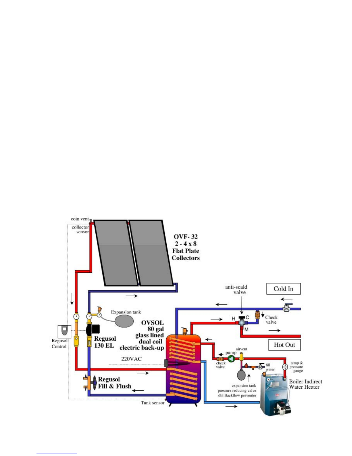
OVSOL System FP-2-DCE / 80 gallon, Flat plate, Dual coil electric tank
System Assembly
Installing OVSOL System FP-2-DCE
Model Number 540 04 08K-DCE
Solar Closed-Loop Domestic Hot Water System
Oventrop Components
Two OVF-32 Flat Plate Solar Collectors . . . . . . . . . . . . . . . . . . . . . . . . . . . . . . . . . . lled weight: 550 lbs.
Regusol 130 EL Solar Transmission Station . . . . . . . . . . . . . . . . . . . . . . . . . . . . . . . lled weight: 20 lbs.
80 Gallon OVSOL glass lined Tank. . . . . . . . . . . . . . . . . . . . . . . . . . . . . . . . . . . lled weight: 970 lbs.
Regusol Fill and Flush Valve
Oventrop NT Propelyne Glycol Antifreeze
System Design Description
The solar closed-loop heating system consists of the Oventrop Regusol 130 EL pump and control station,
one OV-5 evacuated tube collector, and an 80 gallon glass lined tank with two internal coils and an electric backup
element. An expansion tank is installed at the Regusol on the safety group. Oventrop NT propelyne glycol antifreeze
is lled into the closed loop system through the Regusol ll and ush valve.
Cold water is piped to the solar tank. An anti-scald valve must be installed for hot water mixing to hot water
xtures if the solar tank high limit in the Regusol controller is set above 120
the manner of a standard indirect water heater.
o
F. The top coil is piped to the boiler in
082809
57
Page 59
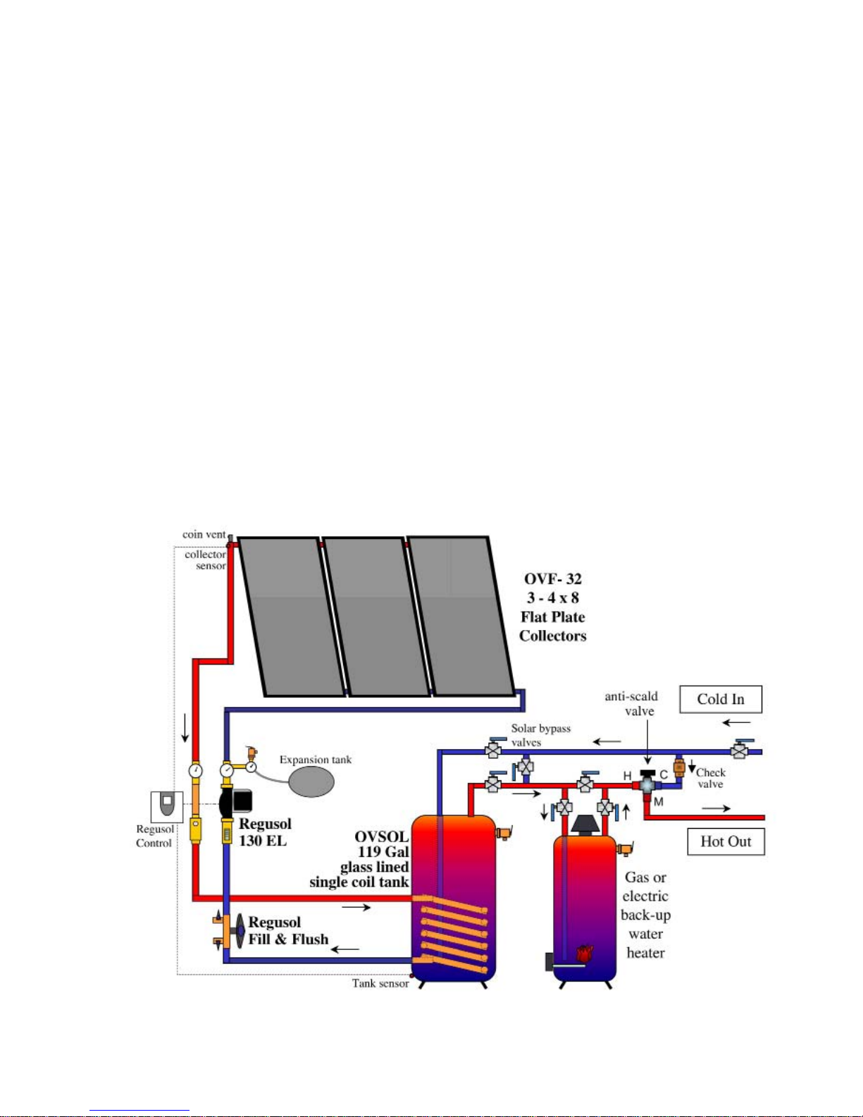
OVSOL System FP-3-SC / 119 gallon, Flat plate, Single coil tank
System Assembly
Installing OVSOL System FP-3-SC
Model Number 540 34 08K-SC
Solar Closed-Loop Domestic Hot Water System
Oventrop Components
Three OVF-32 Flat Plate Solar Collectors. . . . . . . . . . . . . . . . . . . . . . . . . . . . . . . . . . lled weight: 675 lbs.
Regusol 130 EL Solar Transmission Station . . . . . . . . . . . . . . . . . . . . . . . . . . . . . . . lled weight: 20 lbs.
119 Gallon OVSOL glass lined Tank. . . . . . . . . . . . . . . . . . . . . . . . . . . . . . . . . . . lled weight:1315 lbs.
Regusol Fill and Flush Valve
Oventrop NT Propelyne Glycol Antifreeze
System Design Description
The solar closed-loop heating system consists of the Oventrop Regusol 130 EL pump and control station,
one OV-5 evacuated tube collector, and an 119 gallon stainless steel tank with one internal coil. An expansion tank
is installed at the Regusol on the safety group. Oventrop NT propelyne glycol antifreeze is lled into the closed loop
system through the Regusol ll and ush valve.
Cold water is piped to the solar tank and in series with the back-up hot water heater. Solar bypass valves
are installed for servicing the solar tank. Back-up hot water heater bypass valves may be installed to bypass the hot
water heater. An anti-scald valve must be installed for hot water mixing to hot water xtures if the solar tank high
limit in the Regusol controller is set above 120
o
F.
58
082809
Page 60
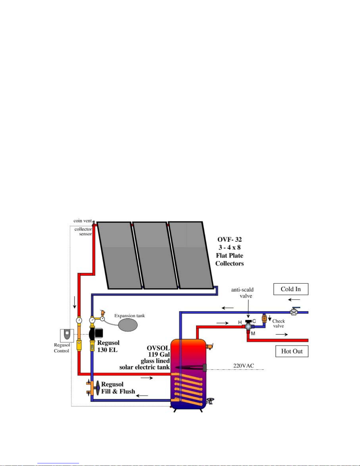
OVSOL System FP-3-SCE / 119 gallon, Flat plate, Single coil electric tank
System Assembly
Installing OVSOL System FP-3-SCE
Model Number 540 34 08K-SCE
Solar Closed-Loop Domestic Hot Water System
Oventrop Components
Three OVF-32 Flat Plate Solar Collectors . . . . . . . . . . . . . . . . . . . . . . . . . . . . . . . . . . lled weight: 675 lbs.
Regusol 130 EL Solar Transmission Station . . . . . . . . . . . . . . . . . . . . . . . . . . . . . . . lled weight: 20 lbs.
119 Gallon OVSOL glass lined Tank. . . . . . . . . . . . . . . . . . . . . . . . . . . . . . . . . . . lled weight: 1315 lbs.
Regusol Fill and Flush Valve
Oventrop NT Propelyne Glycol Antifreeze
System Design Description
The solar closed-loop heating system consists of the Oventrop Regusol 130 EL pump and control station,
one OV-5 evacuated tube collector, and an 119 gallon stainless steel tank with one internal coil and an electric element. An expansion tank is installed at the Regusol on the safety group. Oventrop NT propelyne glycol antifreeze is
lled into the closed loop system through the Regusol ll and ush valve.
Cold water is piped to the solar tank. An anti-scald valve must be installed for hot water mixing to hot water
xtures if the solar tank high limit in the Regusol controller is set above 120
o
F.
082809
59
Page 61
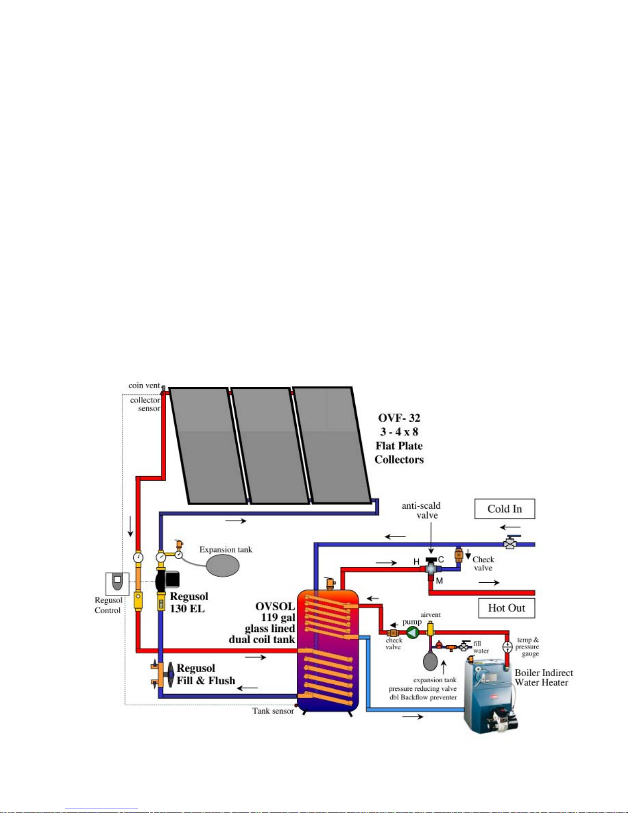
OVSOL System FP-3-DC / 119 gallon, Flat plate, Dual coil tank
System Assembly
Installing OVSOL System FP-3-DC
Model Number 540 34 08K-DC
Solar Closed-Loop Domestic Hot Water System
Oventrop Components
Three OVF-32 Flat Plate Solar Collectors . . . . . . . . . . . . . . . . . . . . . . . . . . . . . . . . . . lled weight: 675 lbs.
Regusol 130 EL Solar Transmission Station . . . . . . . . . . . . . . . . . . . . . . . . . . . . . . . lled weight: 20 lbs.
119 Gallon OVSOL glass lined Tank. . . . . . . . . . . . . . . . . . . . . . . . . . . . . . . . . . . lled weight: 1340 lbs.
Regusol Fill and Flush Valve
Oventrop NT Propelyne Glycol Antifreeze
System Design Description
The solar closed-loop heating system consists of the Oventrop Regusol 130 EL pump and control station,
one OV-5 evacuated tube collector, and an 119 gallon glass lined tank with two internal coils. An expansion tank is
installed at the Regusol on the safety group. Oventrop NT propelyne glycol antifreeze is lled into the closed loop
system through the Regusol ll and ush valve.
Cold water is piped to the solar tank. An anti-scald valve must be installed for hot water mixing to hot water
xtures if the solar tank high limit in the Regusol controller is set above 120
the manner of a standard indirect water heater.
o
F. The top coil is piped to the boiler in
60
082809
Page 62
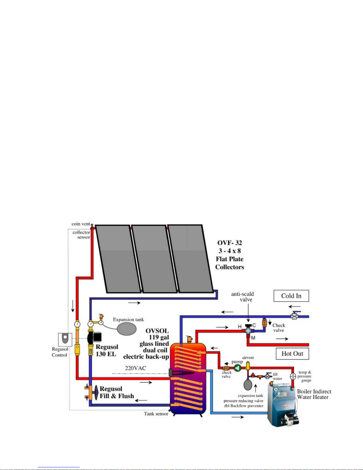
OVSOL System FP-3-DCE / 119 gallon, Flat plate, Dual coil electric tank
System Assembly
Installing OVSOL System FP-3-DCE
Model Number 540 34 08K-DCE
Solar Closed-Loop Domestic Hot Water System
Oventrop Components
Three OVF-32 Flat Plate Solar Collectors . . . . . . . . . . . . . . . . . . . . . . . . . . . . . . . . . . lled weight: 675 lbs.
Regusol 130 EL Solar Transmission Station . . . . . . . . . . . . . . . . . . . . . . . . . . . . . . . lled weight: 20 lbs.
119 Gallon OVSOL glass lined Tank. . . . . . . . . . . . . . . . . . . . . . . . . . . . . . . . . . . lled weight: 1340 lbs.
Regusol Fill and Flush Valve
Oventrop NT Propelyne Glycol Antifreeze
System Design Description
The solar closed-loop heating system consists of the Oventrop Regusol 130 EL pump and control station,
one OV-5 evacuated tube collector, and an 119 gallon glass lined tank with two internal coils and an electric backup
element. An expansion tank is installed at the Regusol on the safety group. Oventrop NT propelyne glycol antifreeze
is lled into the closed loop system through the Regusol ll and ush valve.
Cold water is piped to the solar tank. An anti-scald valve must be installed for hot water mixing to hot water
xtures if the solar tank high limit in the Regusol controller is set above 120
the manner of a standard indirect water heater.
o
F. The top coil is piped to the boiler in
082809
61
Page 63
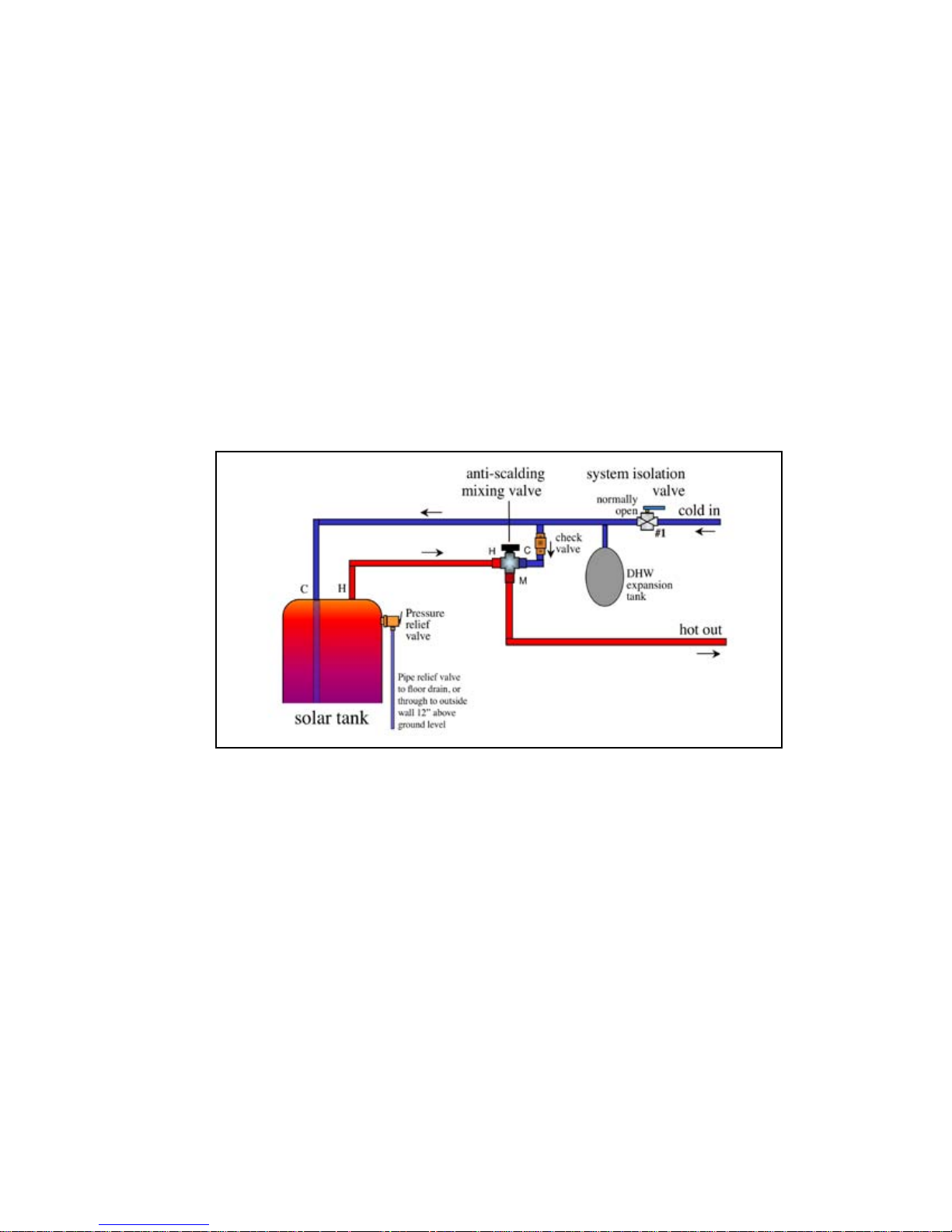
Piping the Solar Tank with Integrated Back-up as a One Tank System
Use 3/4” copper pipe for plumbing the tanks. To prevent heat loss through the copper tubing, insulate all
tubing with at least 1/2” wall tube insulation. This should include the cold water feed to the solar storage tank
up to 6 feet from the tank. A check valve should be installed on the cold water feed line to the mixing valve to
prevent hot water migration into the cold water piping.
The solar tank should include valves and piping for service.
A domestic hot water expansion tank can be installed on the cold water feed to the tanks. The expansion tank
should be installed downstream from a back ow preventer, for cold water feed to the tanks.
Service Valves and Instructions for Emergency
To isolate or service the hot water system in an emergency, turn system isolation valve #1 off.
To leave the system in an unoccupied house when hot water will not be drawn, the solar system should be
drained of antifreeze and the controller turned to “off” or unplugged. You may also turn the system isolation
valve #1 off if no hot water ow to the xtures is desired.
62
082809
Page 64
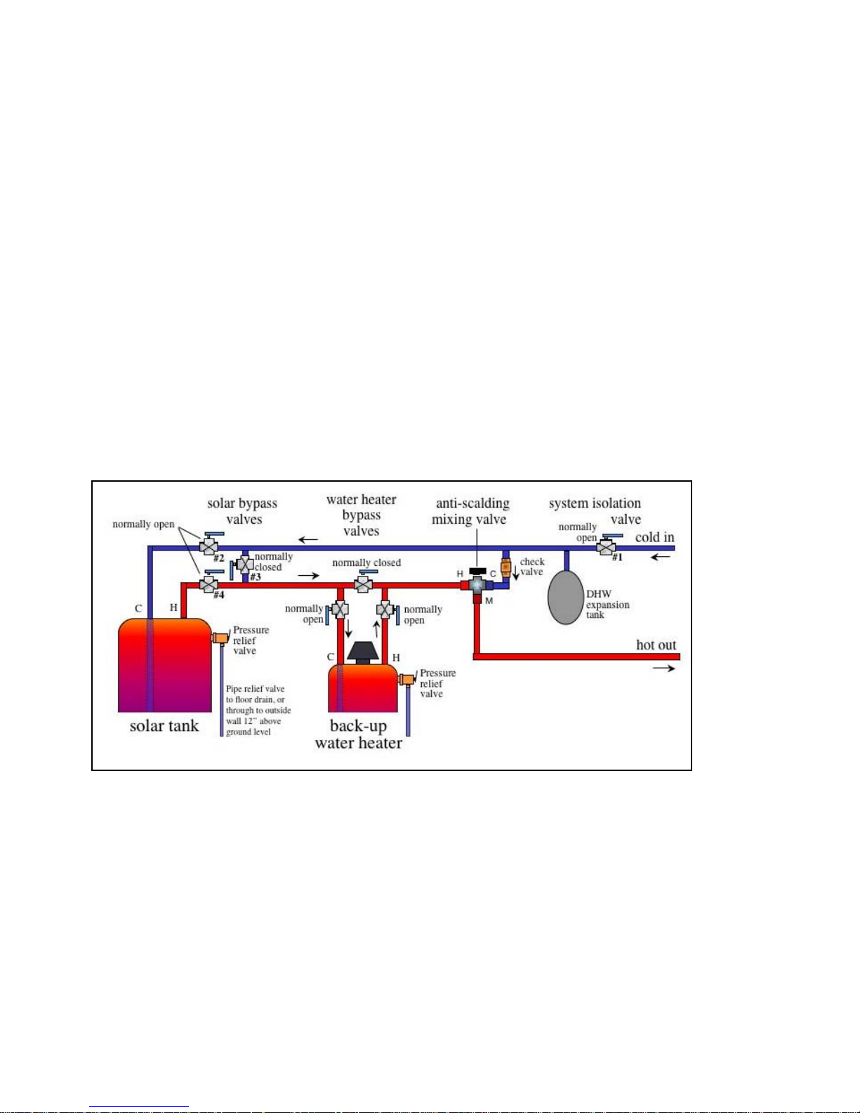
Piping the Solar Tank and the Auxiliary Hot Water Service for Two Tank System
Use 3/4” copper pipe for plumbing the tanks. To prevent heat loss through the copper tubing, insulate all
tubing with at least 1/2” wall tube insulation. This should include the cold water feed to the solar storage tank
up to 6 feet from the tank. A check valve should be installed on the cold water feed line to the mixing valve to
prevent hot water migration into the cold water piping.
The solar tank should include valves and piping for service. In addition, the back-up water heater can have
valves installed for solar hot water bypass.
A domestic hot water expansion tank can be installed on the cold water feed to the tanks. The expansion tank
should be installed downstream from a back ow preventer, for cold water feed to the tanks.
Service Valves and Instructions for Emergency
To isolate or service the hot water system in an emergency, turn system isolation valve #1 off.
To isolate the solar tank from the auxiliary water heater, the normally open solar bypass valves #2 and #4 are
shut off, isolating the solar tank from the supply of water. The normally closed valve #3 is then opened for
bypass. Under no circumstances are valves number 1, 2 & 3 to be left open during solar operation.
To leave the system in an unoccupied house when hot water will not be drawn, the solar system should be
drained of antifreeze and the controller turned to “off” or unplugged. You may also turn the system isolation
valve #1 off if no hot water ow to the xtures is desired.
Piping and Insulating the Solar Loop
When piping collectors, use 3/4” copper for one to four 16-tube collector arrays. Preferably use type L.
Never use PEX plastic tubing. PEX tubing cannot withstand temperatures above 200°F, and fail in
solar loops.
Always insulate solar loops with at least a high temperature elastomeric insulation. This exible rubber foam
insulation may be protected against UV degradation with a mastic or a 15-year latex paint applied to the
surface. High temperature berglass, urethane, and isocyanurates are also used on solar loops and have
jackets that enclose and protect the insulation. Use insulation with at least a 3/4” wall thickness for all outdoor
piping. Always insulate completely around pipe ttings and at the collector ttings. Pay particular attention
to insulation detail at the collector sensor. Copper pipework must be supported by pipe hangers, split ring
hangers or Unistrut clamps. Check your local codes for pipe sizes and support distances for vertical and
horizontal runs. The supports must not hold onto and compress the insulation. Pipe support hangers should
be secured directly to the pipe.
082809
63
Page 65
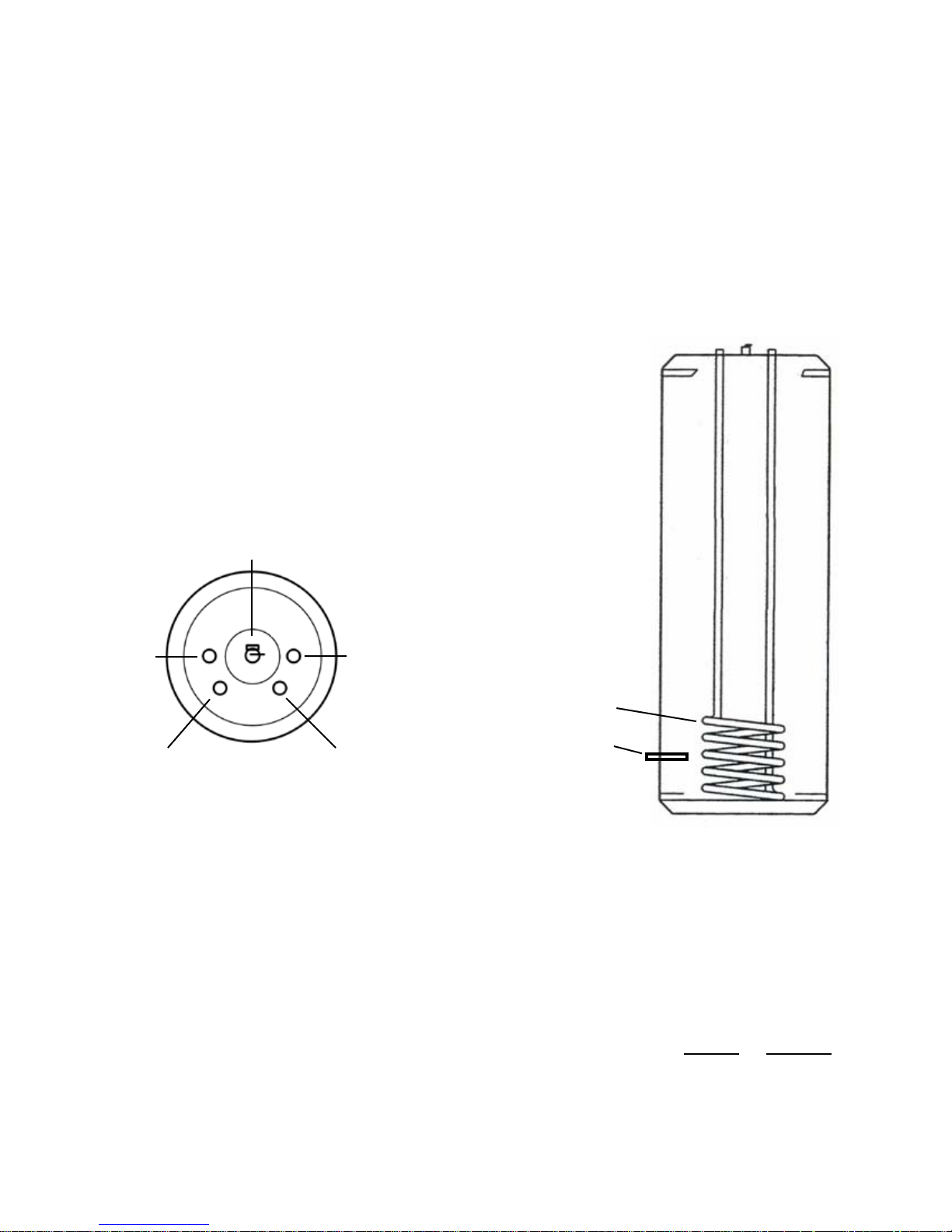
Section Nine
Oventrop Stainless Steel Indirect Solar Hot Water Tanks
Indirect single and dual coil domestic hot water storage tanks are made in 60-, 80-, and 115-gallon models. Each
tank has bottom heat exchanger coil connection for solar heat transfer.
Please read the Installation, Operating and Service Instructions Manual, placed with the tank.
1) Model SC- Solar heating with a single coil.
The units are provided with one 3/8” ID thermal well for installation of the solar tank sensor.
Quality Design and Construction
Tanks and coils are all stainless steel.
Includes over 2” of urethane insulation, R-12.
Thermoplastic jacket will not rust or corrode.
All connections are 1” on top.
Tank ports are clearly marked.
Top View
Side View
T & P valve
cold water in hot water out
solar coil
bottom coil (solar)
return from collector
Locating the Water Heater
The water heater should be located in an area where water leakage from the tank or connections will not result in damage to
areas adjacent to the water heater or to lower oors of the structure. When such a location cannot be avoided, a suitable drain
pan must be installed under the water heater, and the drain pan must be connected to a drain.
The water heater should be installed as close to the back-up hot water heater or boiler as is practical for easy access for service.
The unit is designed for installation on combustible ooring and in alcoves, closets, etc.
The minimum clearances from
combustible surfaces are:
bottom coil (solar)
supply to collector
The minimum clearances
for service are:
solar sensor well
(tank sensor)
Tank Dimensions:
Dimensions
(inches)
Bottom----------------------------0”
Left, right, and rear sides -Front------------------------------1”
Top--------------------------------6”
Bottom--------------------------- 0”
Left, right, and rear sides -- 3”
Front----------------------------- 30”
Top------------------------------- 6”
Height
60 gallon 60 22.5
80 gallon 54 26.5
115 gallon 72 26.5
Diameter
64
082809
Page 66
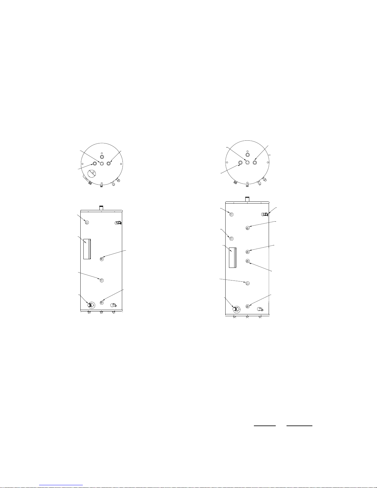
Oventrop Glass-lined Indirect Solar Hot Water Tanks
Indirect single and dual coil domestic hot water storage tanks are made in 80-, and 119-gallon models. Each
tank has bottom heat exchanger coil connection for solar heat transfer with optional upper coil and electric
backup elements.
Please read the Installation, Operating and Service Instructions Manual, placed with the tank.
Quality Design and Construction
Tanks and coils are all glass lined.
Includes over 2” of urethane insulation, R-14.
All tanks have a metal jacket over the insulation.
Electric Elements are 4500W ,240VAC.
HOT OUT
(1” NPT)
ANODE
3/4NPTPort
Optional
Electric
Heating
Assembly
Bottom Sensor
Immersion Well
COLD IN
(1”NPT)
80SCE,
119SC
ONLY
ANODE
FROM SOLAR
(1” NPT)
TO SOLAR
(1” NPT)
Figure 1: 80SC/SCE, 119SC/SCE
HOTOUT(1”NPT)
ANODE
Top Sensor
Immersion Well
Immersion Well
Optional
Electric
Heating
Assembly
Bottom
Sensor
Immersion
Well
COLD IN
(1”NPT)
Figure 2: 80DC/DCE, 119DC/DCE
ANODE
T&P RELIEF VALVE
FROMBOILER(1”NPT)
TOBOILER(1”NPT)
FROM SOLAR
(1”NPT)
TO SOLAR
(1”NPT)
Locating the Water Heater
The water heater should be located in an area where water leakage from the tank or connections will not result in damage to
areas adjacent to the water heater or to lower oors of the structure. When such a location cannot be avoided, a suitable drain
pan must be installed under the water heater, and the drain pan must be connected to a drain.
The water heater should be installed as close to the back-up hot water heater or boiler as is practical for easy access for service.
The minimum clearances from
combustible surfaces are:
Bottom----------------------------0”
Sides (non-piping) ------------0”
Front------------------------------0”
Top--------------------------------0”
082809
The minimum clearances
for service are:
Side (T&P Relief) ------------ 6”
Sides (non-piping) ----------- 4”
Front----------------------------- 16”
Top------------------------------- 12”
Tank Dimensions:
Dimensions
(inches)
Height
80 gallon 64 24
119 gallon 65 28
Diameter
65
Page 67
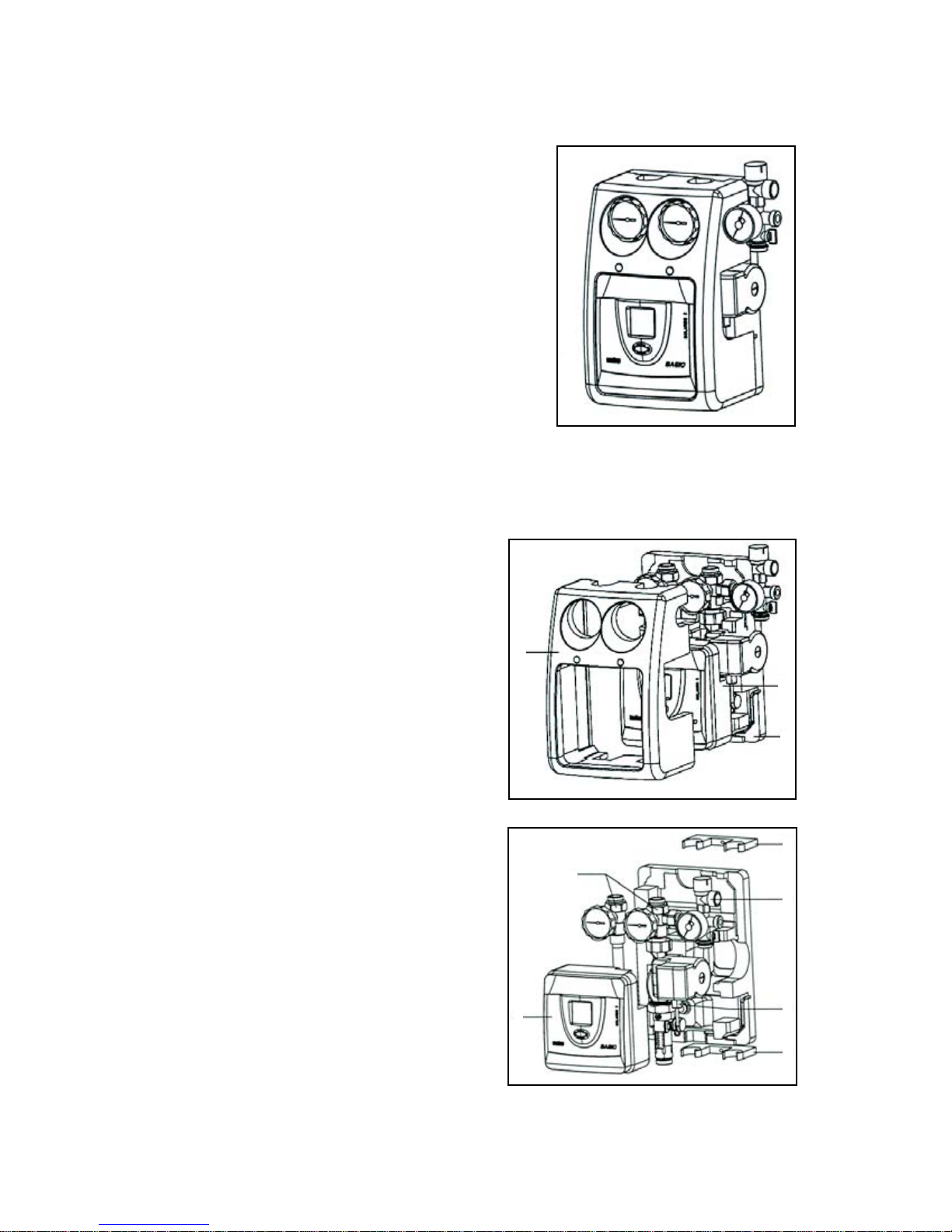
Transmission station
with deaerator
“Regusol EL-130”
Installation instructions
Transmission station “Regusol EL-130” with pre-assembled,
integrated microprocessor-driven control.
The transmission station is supplied with a detailed
instruction manual of the control.
The “Regusol EL-130” is equipped with a deaerator for
air elimination from the heat transfer medium.
Safety notes
The safety notes are to be observed.
Installation, initial operation, maintenance and repairs
have to be carried out by authorized and qualied trade persons.
Installation notes
The transmission station is supplied pre-assembled.
Pump wiring (5) is necessary.
Compression ttings for 3/4” copper pipe are included.
The transmission station always has to be mounted at a lower
level than the collectors.
Assembly notes
Remove transmission station from the packaging.
Pull the front insulation (1) from the control retainer (2)
while pushing the control retainer against the back insulation (3).
Now the control retainer can be pulled off the back insulation
together with the control (4).
Remove transmission station (6).
For each wall-mounting device (7), drill 5/16-inch holes
at a distance of 10 5/16 inches.
Fix mounting device by screwing it onto the wall and engage
back insulation. Now push transmission station onto the
xing clips of the wall mounting device.
Connect the Regusol to the collectors (top connectors) and the tank
(bottom connectors) through the Regusol compression ttings.
See diagram 1 for details. Use 3/4” hard copper to pipe. The pipe
ends must be cut at right angles and be free of burrs. Apply clear
plumber’s grease on the compression nut thread and rings. Slide in
pipe until stop and rmly tighten the compression ttings. Hold rm
while tightening.
(Continued on next page)
1
2
3
7
6
8
4
5
7
66
082809
Page 68
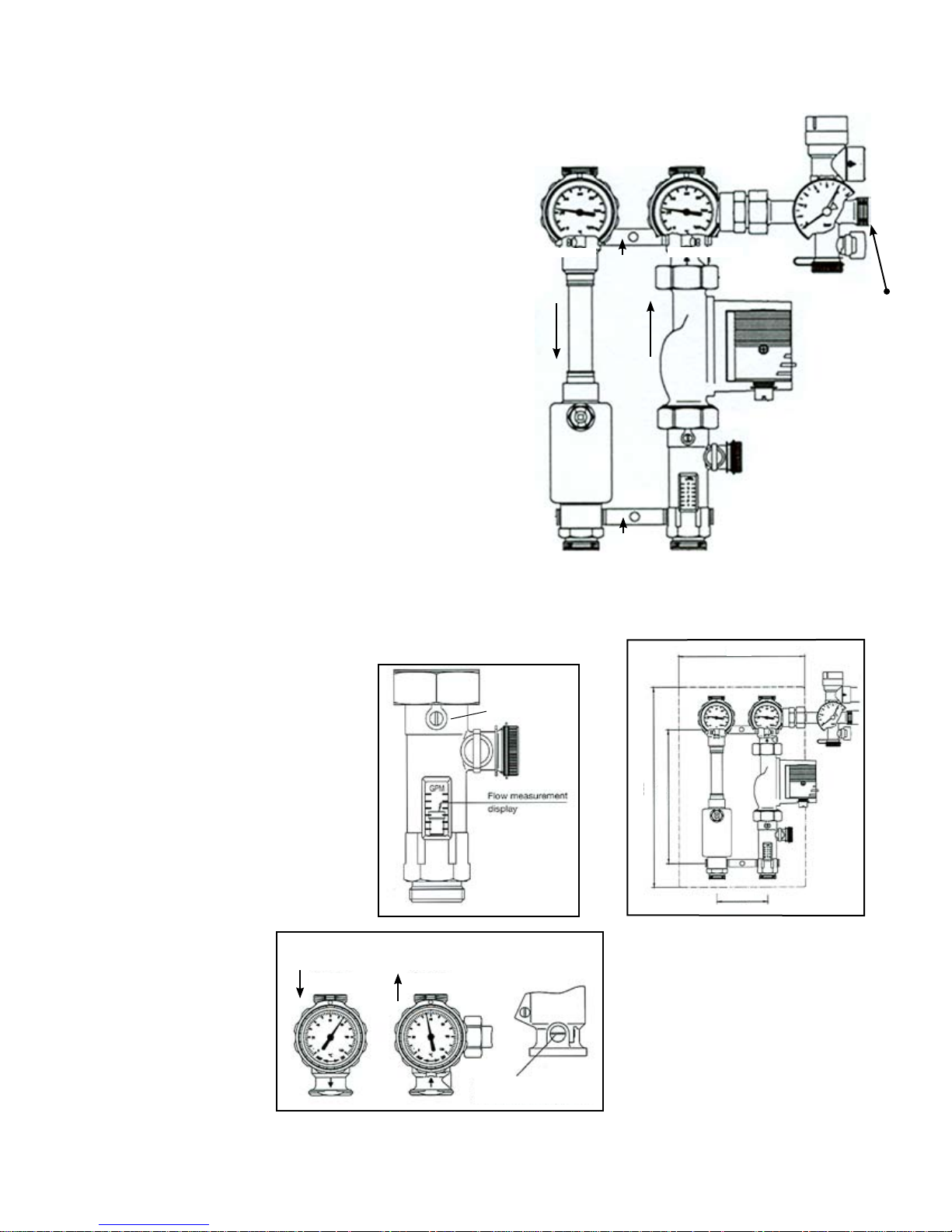
Screw safety group (8) onto the ball valve.
Install discharging pipe from the pressure relief valve to the
oor or through exterior wall to 12” from ground level.
If there is no oor drain, a bucket may be placed under
discharge pipe.
Connect piping of 1/2” male pipe thread on the safety group
to an expansion tank.
Connect cable to the pump (diagram 2) and push control
retainer with the control onto the back insulation.
Now the front insulation can be slipped over the control
retainer and be pushed onto the back insulation until it clicks
into position.
Air test all pipework on solar closed loop. Flush solar installa-
tion thoroughly, then ll the system with Oventrop solar uid.
Adjust the ow rate with the screw slot in the ow measuring
device.
Open vent with radiator vent key on deaerator to remove any
air separated from solar transfer uid.
Make sure thermometers are left in their vertical position,
as valve handles must be left open. Check that the screw
slot on the supply side check valve is left in the horizontal
position.
Connection to collector(s)
Return from Supply to
Thermometer
Deaerator
Connection Connection
supply to tank return from tank
Mounting
bracket
Direction
of ow
Mounting
bracket
Thermometer
Pressure
relief valve
Pressure
gauge
Expansion tank
connection
Circulator
Diagram 1
Flow meter
9- 7/8’’
Typical ow rates are set to
3/4 to 1 gpm per collector*
*16 tube model collector
Collectors
Flow restrictor
screw slot
14- 3/4’’
10- 5/16’’
3- 7/8’’
SupplyReturn
Thermometers in solar collection
mode (displayed on the controller)
will indicate a temperature rise on the
o
return side of an average of 10 - 25
F.
This temperature rise indicates that the
Check valve
slot in horizontal position
collectors are collecting and transferring
solar energy.
082809
67
Page 69
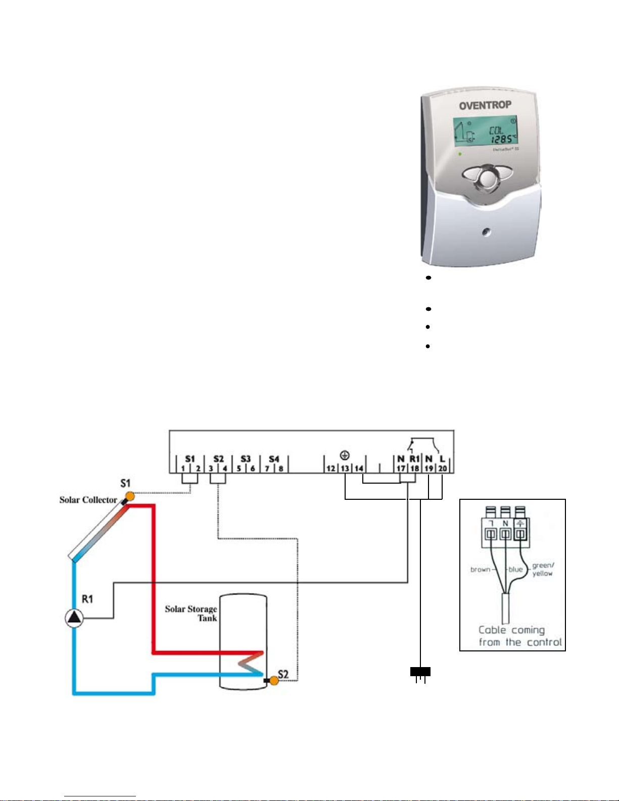
Oventrop Regusol 130 EL Controller
Standard Solar Domestic Hot Water System
Wiring
Warning!
Do not plug in Deltasol controller until all wiring connections are made.
The unit must only be located internally. It is not suitable for installation in wet or
hazardous locations and should not be sited near any electromagnetic eld.
Sensor wires are installed separately from any 120 VAC power chords.
The type of wire installed from the sensors to the controller should be sunlightresistant shielded copper wire with at least two conductors at 18
AWG.
1. Unscrew the cross-recessed screw of the cover and remove it from the housing.
2. Wire the collector sensor and tank sensor wires (S1 & S2).
3. Wire the Regusol Wilo pump as follows:
yellow with green strip wire – ground
blue wire – neutral N #17
brown wire – hot R1 #18
4. Wire the outlet plug as follows:
green wire – ground
white wire – neutral N #19
black wire – load L #20
5. Replace cover.
The power supply to the controller must be made last.
single relay
differential controller
sensor monitoring
on/off/autocontrol
operations hour counter
Wiring and operation instructions
are included with the Regusol
Operating instructions are included with the solar controller.
Control board under cover
Diagram 2
Ground
S1 Collector sensor
S2 Storage sensor low
R1 Solar pump
120 VAC
Plug wired to Deltasol
Regusol EL 130 Pump
Wiring Guide
68
082809
Page 70
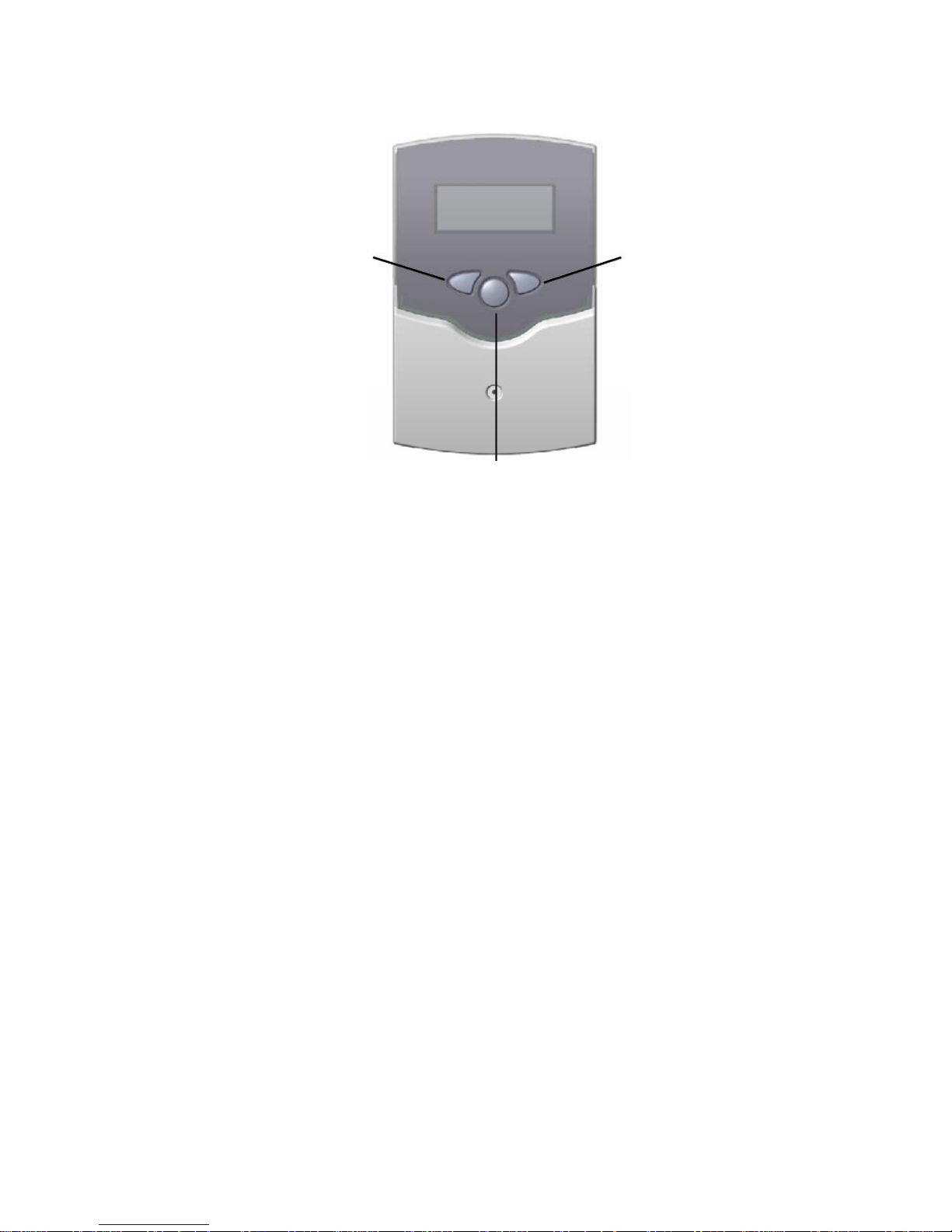
Operation and Programming the Regusol Controller
Display
Backward
Used for scrolling backward
through the menu or to decrease
the adjustment value
2
Operating Mode and Display
Forward or backward buttons will
indicate following information:
COL: Collector sensor temperature
TST: Tank temperature
hP: Operating hours counter
Press “Set” key for programming mode
Programming Mode
To begin programming mode, press forward key to hP
display.
Press and hold forward key 1 in “hP” mode for
2 seconds.
Menu mode displays next indicator (DT 0) and may now be scrolled
through rest of programmable settings using keys 1 or 2 (forward or
backward through the entire menu).
Values in display settings may be changed by pressing “Set” (key
3). The “Set” icon will blink while in programming mode. Raise or
lower values with keys 1 or 2. Press set button once more to complete change. “Set” icon will stop blinking.
Program Changes
“DT 0” differential turn on set point
The rst program display will be “DT 0” differential turn on set point.
DT 0 is set at 12 ºF. This indicates what turn on temperature the
collectors must be above the tank to begin solar circulation. No
change is necessary.
Forward
Used for scrolling forward
through the menu or to
decrease the adjustment value
3
Set
1
Program Changes
Mode of Operation ON / OFF / AUTO
“HND 1”
Scroll through menu to “HND 1” display, near the end of the
program menu. This is for the setting switch ON, OFF, or
AUTO that allows the controller the function of operation.
It is a service operation switch.
ON position energizes the pump to circulate at all times.
OFF position keeps the pump from circulating.
AUTO allows the controller to operate the pump based on the
differential temperatures (normal operation).
Default setting is AUTO. To change press “Set” (key 3). Press
key 1 or 2 to change into ON, OFF or AUTO mode. Press set
key 3 again to complete change and before moving into the
next menu.
Always leave the controller in AUTO for normal solar collection
cycling.
“S MX” storage maximum set point
“S MX” is set at 140 ºF. This setting can be turned up only if
there is a anti-scald valve installed on the DHW system.
“DT F” differential turn off set point
The second indicator will be “DT F” differential turn off set point. DT
F is set at 5 ºF. This indicates what turn-off temperature the collectors must be above the tank for solar circulation to end. No change
is necessary.
082809
To change press “Set” (key 3). Press key 1 to increase or 2 to
decrease the storage maximum temperature. Press set key
again to set change.
69
Page 71

Operating and Programming the Regusol Controller
Program Changes
The factory settings for the following displays are suitable for all solar domestic hot water heating. For more information
on these settings, read the control manual included with the Regusol 130.
“EM” limit collector temperature
Factory setting: 285o F
“OCX” system cooling
Factory setting: OFF
“OCN” Minimum collector limitation
Factory setting: OFF
“OCF” antifreeze function
Factory setting: OFF
The settings for the following displays are as follows.
“LANG” language
Factory setting: En (english)
“UNIT” Temperature in degrees
Factory setting: FAH (fahrenheit)
“OREC” option recooling
Factory setting: OFF
“O TC” tube collector special function
Factory setting: OFF
“OHQM” heat quantity balancing
Factory setting: OFF
“PROG”
Controllers program
“VERS”
This indicates the program version
70
082809
Page 72
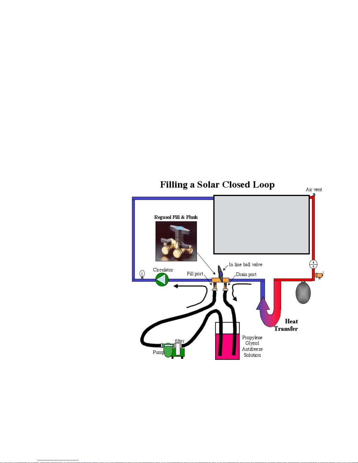
Section Ten
Collector Flush, Leak Check, and Fill Procedure
Before proceeding with the instructions outlined in this section, the solar storage tank should be
lled with water. The collector loop then should be leak checked, ushed, and lled. A Regusol
“ll and ush” valve should be installed for system charge-up. Filling or “charging up” a solar
closed loop incorporates a 1/2 HP utility pump available through most Oventrop dealers.
Leak Check and Flush
1. To ensure there are no leaks, air test the system to approximately 60 PSI. Check and repair
any leaks. When the solar loop is leak-free, release air and ush system with tap water.
2. Before lling the collector loop with antifreeze solution, it must be ushed free of any ux,
copper lings, or debris. Straight tap water may be used for this purpose.
3. To perform this step, hook up a hose from tap faucet to the ll port and run another hose
from the drain port to a drain or outdoors. Close center ball valve on “ush and ll.” Open water
tap to begin ushing. Flush the system with tap water for approximately 10 minutes to assure
there is no solder, ux, or debris left within the collector loop piping.
This step may also be used to cool the collectors before lling the system with propylene glycol.
Fill Procedure
Charging the collector loop
will require approximately 3
- 8 gallons of Oventrop NT40 antifreeze (provided).
It is a premixed waterpropylene glycol solution
of 40% propylene glycol to
60% water and will provide
freeze protection to -6 oF.
No mixing is necessary.
Oventrop
Solar Collector
Array
If collector loop is to be
charged during the sunlight
hours, collectors should
be covered for at least one
hour before beginning; or
the collector may be cooled
with water using procedure
in step 3 (above).
Connect pressure side of
charge pump with washing
machine hoses to the ll
port. From suction side of charge pump, attach another hose to the bucket of the propylene
glycol solution. Attach another hose from the drain port to an empty bucket. If the system was
just ushed with water, drain down the water pressure to prime the charge pump. Drain water
pressure into empty buckets.
Set up for lling with solar heat transfer uid. Turn center ball valve of “Regusol ll and ush”
perpendicular to have propylene glycol ow throughout solar closed loop.
082809
71
Page 73

Turn on ll rig and pump propylene glycol. If pumping out water, have an empty bucket on the
drain port hose to collect water until the color of antifreeze returns. Then put drain port hose
into antifreeze bucket for circulating antifreeze. Run the charge pump until no air bubbles
are seen returning to the bucket. Periodically close drain port to allow pressure to build, then
reopen to purge any air that may be trapped. Watch for air escape. Repeat this procedure until
air is no longer returning to the ll rig pail.
To complete system ll and charge, close the drain port and ll system to pressure of 30 to 35
psi. Close ll port and turn off charge pump. Turn center ball valve of “Regusol ll and ush”
parallel to direction of ow to have propylene glycol ow throughout solar closed loop installation with the system pump in operation. Cover ll and drain ports with hose caps.
Open air vent atop solar collector to eliminate any air trapped at the high point of the system.
Next open the air vent to remove air from the deaerator at the Regusol 130 EL.
Commissioning the System
Before activating system the following checks should be made:
l
System lled with water (tank).
l
Appropriate cold and hot water bypass valves are set for series water ow through tank(s).
l
Collector and tank sensors connected.
l
Regusol is wired and solar loop is air-tested for leaks.
The collector loop can now be lled with the recommended anti-freeze.
Once the solar loop is lled, place Regusol thermometer handles in the fully open position and
the ll and ush valve in fully open position.
Plug in the Regusol controller for operation.
Controller will start and be in automatic mode of operation.
Digital display and indicator light should illuminate.
If the collector temperature is above the tank temperature by 12º F, the circulator should start
and run. Flow meter will indicate circulation. If there is noise of air circulating through the
pump, the system must be recharged to remove air bubbles. Solar closed loops must be free
of air bubbles.
If the collector temperature is below the tank temperature, circulator should not run.
If circulator is not running, set the controller to the “On” position (see Operation and Control-
ling the Regusol Controller) to check circulator operation and indication of ow. Remember to
leave the solar controller set in the “Auto” mode of operation when completed.
If circulator fails to operate, refer to Troubleshooting checks on the following pages.
It is unlikely that system malfunctions will develop within the Regusol. Should they occur,
however, the following procedures will prove helpful. Several of the procedures indicated require the use of test equipment, such as a volt-ohmeter with 10K scale. If this equipment is not
available to you, contact your authorized Oventrop dealer or distributor for service.
72
082809
Page 74

Section Eleven
Trouble Shooting
1. Controller does not come
on.
2. Circulator does not start or
run in “on” position.
3. Circulators will not run
with switch in “auto”
4. Circulator runs constantly
in “auto”
5. Inadequate solar loop
temperature.
A. Controller is not plugged in
B. Breaker tripped to off
C. Blown fuse in controller
D. Inoperative controller
A. Shaft bound
B. Blown fuse or breaker
C. Bad electrical connection
D. Inoperative controller
A. Same as A through D
indicated above
B. Inoperative sensor circuits
C. Poorly attached or insulated
sensors
D. Inadequate temperature
differential
A. Inoperative sensors or
sensor wire circuits
B. Inoperative controller
A. Recent heavy usage of hot
water
C. Inoperative circulator
D. Collector shading
E. Ambient conditions
F. Steam lock at solar collector
A. Check to see if plug is in outlet
B. Reset breaker
C. Replace fuse
D Replace controller
A. Remove plug at rear of circulators and
insert screw driver into slotted end of
shaft; turn to loosen shaft
B. Replace fuse; or reset breaker
C. Tighten connections
D Replace controller
A. Same as A through D indicated above
B. Check sensor circuits and wiring
C. Reattach or reinsulate
D. System will not operate until preset
conditions are met
A. Check sensor circuits and wiring,
check for short in collector sensor
circuit or open in tank sensor circuit
Replace sensor wire or sensors
B. Replace controller
A. Wait until system temperature is
replenished
C. Remove plug at rear of circulator
and insert screwdriver into slotted end
of shaft, turn to loosen shaft
D. Remove shading obstacles
E. Wait until preset conditions are met
F. Recharge solar closed loop to remove
air from antifreeze solution
6. System losing temperature
at night.
082809
A. Inoperative check valve(s)
B. Inoperative controller
C. Inoperative sensor
circuits
A. Make sure check valves in Regusol
are not stuck open
B. Replace controller
C. Check sensor circuits and wiring
73
Page 75
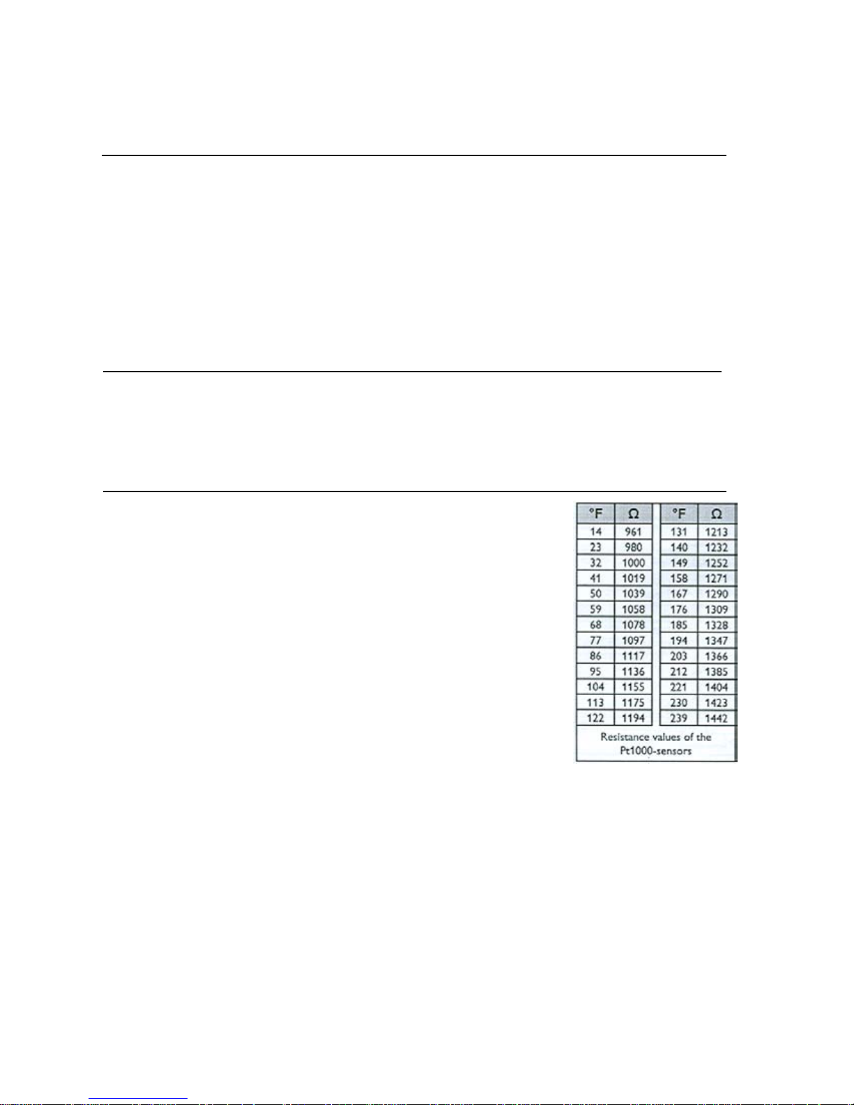
Trouble Shooting
Trouble Probable Cause Remedy
7. Inadequate hot water
delivery temperature.
8. Tank pressure temperature
relief valve blowing off.
A. Recent heavy usage of hot
water
B. Inoperative mixing valve
C. Ambient conditions
D. Inoperative back-up hot
water heater
E. Inoperative existing system
during periods of low solar
insulation
A. Inoperative P/T relief valve
B. Hot water storage tanks
building too much pressure
C. Water main pressure too
high
A. Wait until system temperature is
replenished
B. Adjust or replace mixing valve
C. Wait until preset conditions are met
D. Replace back-up tank or service
thermostat or element in electric hot
water heater (this should be done by
licensed electrician)
E. Contact appropriate service
A. Replace P/T valve
B. Install hot water expansion tank
C. Install Pressure regulator on cold
water supply
Sensor Test
Use an Ohm meter to measure the resistance of the sensor circuit. If an
open circuit or a short circuit situation is detected, then inspect the sensor
wiring before suspecting the sensor. Measure the sensor resistance
without the interconnecting wire before removing the sensor.
The resistance should match the chart for a given temperature.
Maintenance Procedures
Cleaning. The solar collectors will not require cleaning in a climate in which there
is periodic rainfall. A light coating of dust will not seriously affect performance. In
dry, dusty climates, collectors should be cleaned occasionally.
Circulators and Controller. No scheduled maintenance is required for the uid
lubricated circulators or controller system. In the event of a circulator or controller
malfunction, refer to troubleshooting Checks.
Collector Loop Fluid. Collector loop uid must be changed in order to maintain adequate freeze and
corrosion protection. Antifeeze checks should be performed annually. Collector loop uid should be replaced
every 5 - 7 years. To prevent elevated temperatures from developing at the collectors, do not turn the system
off while absent from premises for extended periods.
Solar Storage Tank. Periodically drain a small amount of water from the bottom of tank to prevent sludge or
sediment buildup in the solar storage tank.
Scaling. If your water supply contains a large percentage of minerals (hard water), we strongly recommend
that a water softening device be installed to protect not only the stainless steel solar storage tank and coils
but also the existing hot water heater and its plumbing as well.
74
082809
Page 76

Projections for various components average life cycle
OVSOL 5 evacuated tubes: expected lifetime against vacuum loss . . . . . . . . . . . . 15 - 20 years
OVF-32 at plate collectors . . . . . . . . . . . . . . . . . . . . . . . . . . . . . . . . . . . . . . . . . . . 15 - 20 years
Dual or single coil indirect glass lined tanks: good water quality . . . . . . . . . . . . . . . 20+ years
Regusol 130 EL: Oventrop PE Controller and sensors, Wilo circulator . . . . . . . . . . 10 - 15 years
All inquiries should be made to the product manufacturer:
Oventrop Corporation
PO Box 789
29 Kripes Road
East Granby, CT 06026
Ph. (860)413-9173
www.oventrop-us.com
082809
75
Page 77

Section Twelve
Oventrop Corporation - Limited Warranty
Oventrop Corporation warrants to its “Customers” that all Oventrop products, used for heating and plumbing
applications and sold in accordance with these warranty provisions, shall be free from defects in material and
workmanship. “Customer” as used herein shall mean an end-user of Oventrop products.
Five (5) years for all solar components from the date of purchase, unless otherwise specied in writing.
Ten (10) years for evacuated tube collector from date of purchase, unless otherwise specied in writing.
Limited Lifetime for stainless steel indirect water heater fteen (15) years from date of purchase, unless otherwise
specied in writing.
In order to be eligible for a warranty claim, products sold
(1) must be installed and maintained professionally according to the relevant assembly instructions and the
product manual,
(2) must only be used for purposes provided in the Oventrop Corporation’s product description or assembly
instructions,
(3) must be exposed only to gaseous or liquid media approved for the product by Oventrop Corporation, and
(4) shall not be combined with products of other manufacturers unless otherwise stated in the product manual.
Oventrop Corporation’s sole obligation hereunder shall be, at its option, to issue credit, repair or replace any
component or part thereof which is proved to be defective. The limited warranty does not cover cost for
transportation or labor charges (including installation and removal) unless such charges are authorized in writing
in advance by the Oventrop Corporation. Any repairs without the express written consent of Oventrop
Corporation shall render this limited warranty invalid. Oventrop Corporation disclaims allowances for
dismounting and consequential losses and damages.
Warranty claims must be received by Oventrop Corporation within the applicable warranty period and within
thirty (30) days from when the cause for the claim occurred or was discovered. Upon receipt of prompt notice
of a warranty claim, Oventrop Corporation shall have ten (10) business days in which to determine whether it
acknowledges responsibility for any asserted defects in material or workmanship and the appropriate action to be
taken.
This limited warranty and any claims arising from the breach of warranty, or any other claim arising hereunder,
shall be governed and construed under the laws of the State of New York. No other persons than Oventrop
Corporation employees have any expressed or implied authority to bind Oventrop Corporation to any agreement
or warranty of any kind without the express written consent of Oventrop Corporation.
Disclaimer of Warranties:
OVENTROP CORPORATION DISCLAIMS ANY WARRANTY NOT PROVIDED HEREIN INCLUDING
THE IMPLIED WARRANTY OF MERCHANTABILITY AND IMPLIED WARRANTY OF FITNESS FOR A
PARTICULAR PURPOSE. IT IS EXPRESSLY UNDERSTOOD THAT OVENTROP CORPORATION IS NOT
RESPONSIBLE FOR ANY CONSEQUENTIAL OR OTHER DAMAGES THAT MAY ARISE FROM USING
OVENTROP CORP. SYSTEM COMPONENTS. DAMAGE RESULTING FROM WATER FREEZING IN THE
TUBING DOES NOT CONSTITUTE A DEFECT IN MATERIAL OR WORKMANSHIP, AND SHALL NOT
BE COVERED BY THIS WARRANTY. OVENTROP TUBING MAY NOT BE STORED IN DIRECT
SUNLIGHT FOR ANY PERIOD LONGER THAN THREE WEEKS, OR THIS LIMITED WARRANTY
BECOMES INVALID. OVENTROP CORPORATION DISCLAIMES ANY STATUTORY OR IMPLIED
WARRANTY OF HABITABILITY. OVENTROP CORPORATION FURTHER DISCLAIMS ANY
RESPONSIBILITY FOR LOSSES, EXPENSES, INCONVENIENCES, SPECIAL, INDIRECT, SECONDARY,
INCIDENTAL, OR CONSEQUENTIAL DAMAGES ARISING FROM OWNERSHIP OR USE OF THE
ARTICLES SOLD HEREUNDER.
THERE ARE NO WARRANTIES WHICH EXTEND BEYOND THE FACE HEREOF.
76
082809
 Loading...