

oventrop Hydromat DP, Hydromat DP DN 25, Hydromat DP DN 15, Hydromat DP DN 20, Hydromat DP DN 32 Technical Information
...Page 1
2009 Oventrop 1
Differential pressure regulator
”Hydromat DP“
DN 15 to DN 50
Technical information
The Oventrop Quality Management
System is certified to DIN-EN-ISO 9001
Differential pressure regulator “Hydromat DP”
Measuring technique “classic”
Tender specification:
Oventrop differential pressure regulator “Hydromat DP“ for a constant control of the set nominal value as proportional regulator
working without auxiliary energy.
Infinitely adjustable nominal value between 50 and 300 mbar
or 250 and 700 mbar which can be locked and be read-off from
the outside at any time. With hidden isolating facility and with ball
valve for draining and filling, installation in the return pipe, oblique
pattern. Valve disc with soft seal.
Valve body, bonnet and regulator housing made of bronze, valve
disc and stem made of brass resistant to dezincification (DZR),
O-rings, washer and diaphragm made of EPDM.
Max. working temperature t
s
: +120°C
Min. working temperature t
s
: -20°C
Max. working pressure p
s
: 10 bar
Max. differential pressure: DN 15 – DN 40: 2 bar
DN 50: 3 bar
Length of capillary: 1 m
Differential pressure regulator, both ports female thread according
to EN 10226
Item no. Item no.
Size kvs 50 up to 300 mbar 250 up to 700 mbar
DN 15 2.5 106 45 04 106 47 04
DN 20 5.0 106 45 06 106 47 06
DN 25 7.5 106 45 08 106 47 08
DN 32 10.0 106 45 10 106 47 10
DN 40 15.0 106 45 12 106 47 12
DN 50 34.0 106 45 16 106 47 16
Differential pressure regulator, both ports male thread with collar
nut
Item no. Item no.
Size kvs 50 up to 300 mbar 250 up to 700 mbar
DN 15 2.5 106 46 04 106 48 04
DN 20 5.0 106 46 06 106 48 06
DN 25 7.5 106 46 08 106 48 08
DN 32 10.0 106 46 10 106 48 10
DN 40 15.0 106 46 12 106 48 12
DN 50 34.0 106 46 16 106 48 16
Advantages:
- all functioning components on one level
- infinitely adjustable nominal value
- very good optical display of the set nominal value
- nominal value can be locked
- simple isolation of the pipe
- ball valve for filling and draining of the riser
-pressure balanced valve disc
- existing double regulating and commissioning valves can be
converted to differential pressure regulators
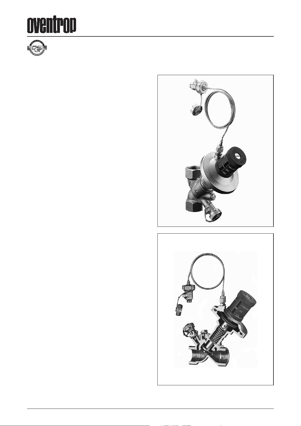
Cut illustration
Page 2
2009 Oventrop2
Function:
The Oventrop differential pressure regulators are proportional
regulators working without auxiliary energy. They are designed for
use in heating or cooling systems to maintain a constant differential pressure within a necessary proportional band. The spring for
nominal pressure can be adjusted by use of the nominal value
setting device. The outer chamber of the diaphragm regulator
must be connected to the capillary, and the capillary to the supply
pipe. With the differential pressure in the installation increasing,
the valve disc closes down and opens as the differential pressure
falls. The excess differential pressure is reduced by the differential
pressure regulator, until the set differential pressure in the pipe is
reached.
Installation of the regulator:
Oventrop differential pressure regulators “Hydromat DP“ are installed in the return pipe. Installation is possible in any position
provided the direction of flow conforms with the direction of the
arrow on the valve body. Before installing the regulator into the
pipework, it is advisable to flush the latter thoroughly. The installation of an Oventrop ”Y“ type strainer is recommended. The capillary should be fitted above or horizontal to the supply pipe, but
not from underneath where it might be prone to get blocked by
dirt particles.
Pressure test of the installation only with the capillary being connected.
Setting the nominal value:
The nominal value of the Oventrop differential pressure regulator
is infinitely adjustable. To do so, loosen locking screw and turn
handwheel to the desired nominal value. Then retighten locking
screw.
Operation of the manual isolation:
The Oventrop differential pressure regulator “Hydromat DP“ can
be closed off manually, e.g. for maintenance works, and thus additionally acts as an isolating valve. To isolate the regulator manually, remove locking screw from the handwheel and close valve
with a 3 mm Allen key with the capillary of the upper chamber of
the diaphragm regulator being connected to the supply pipe.
If the regulator shall be reopened after servicing, reopen screw
fully with the Allen key. A perfect regulation is only possible in this
position.
Draining and filling of the installation:
The installation may be drained and filled with the help of the two
ball valves. Close the ball valve in the supply pipe before dismantling the capillary. During this operation, a minimum amount of
water may escape. Fit
1
⁄2" hoses onto both ball valves and open
valves to drain or fill the installation.
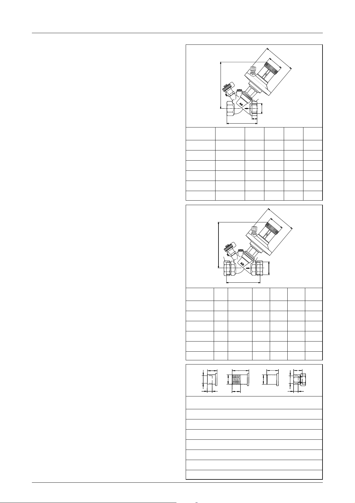
Dimensions:
300
400
200
100
100
200
300
Item no.
D
tSW*L H
EN 102266
106 45/4704 Rp
1
⁄2 13.2 27 80 158
106 45/4706 Rp
3
⁄4 14.5 32 84 160
106 45/4708 Rp 1 16.8 41 97.5 163
106 45/4710 Rp 1
1
⁄4 19.1 50 110 172
106 45/4712 Rp 1
1
⁄2 19.1 54 120 178
10645/4716 Rp 2 25,7 70 150 210
300
400
200
100
100
200
300
Item no. DN SW1*SW2*L H
10646/4804 15 G
3
⁄4 27 30 88 158
10646/4806 20 G 1 32 37 93 160
10646/4808 25 G 1
1
⁄4 41 46 110 163
10646/4810 32 G 1
1
⁄2 50 52 110 172
10646/4812 40 G 1
3
⁄4 54 58 120 178
10646/4816 50 G 2
3
⁄8 65 75 150 210
DN D1 L1 L2 L3 L4 D3 L5 L6 L7
15 15 18 12 R
1
⁄2 31 13.2 20.5 50 Rp 1⁄2 37 13.2
20 18 23 15 R
3
⁄4 34 14.5 26 50 Rp 3⁄4 39 14.5
20 22 24 17
25 28 27 20 R 1 40 16.8 33 60 Rp 1 53 16.8
32 35 32 25 R 1
1
⁄4 46 19.1 41 60 Rp 11⁄4 55 19.1
40 42 37 29 R 1
1
⁄2 49 19.1 47.5 65
50 54 50 40 60 65
D
2
EN 10226
D4
EN 10226
H
D
L
SW
Ø104
Ø48
H
L
SW
1
SW
2
Ø104
Ø48
L2
D1
D2
D3
D4
L3
L1
L5
L6
L4
L
7
D
ISO 228
t
Differential pressure regulator “Hydromat DP”
DN 15 to 50
* SW = spanner size
100
200
100
300
200
400
300
0
0
1
0
0
2
0
0
1
0
0
3
0
0
2
4
0
0
0
0
3
Page 3
2009 Oventrop 3
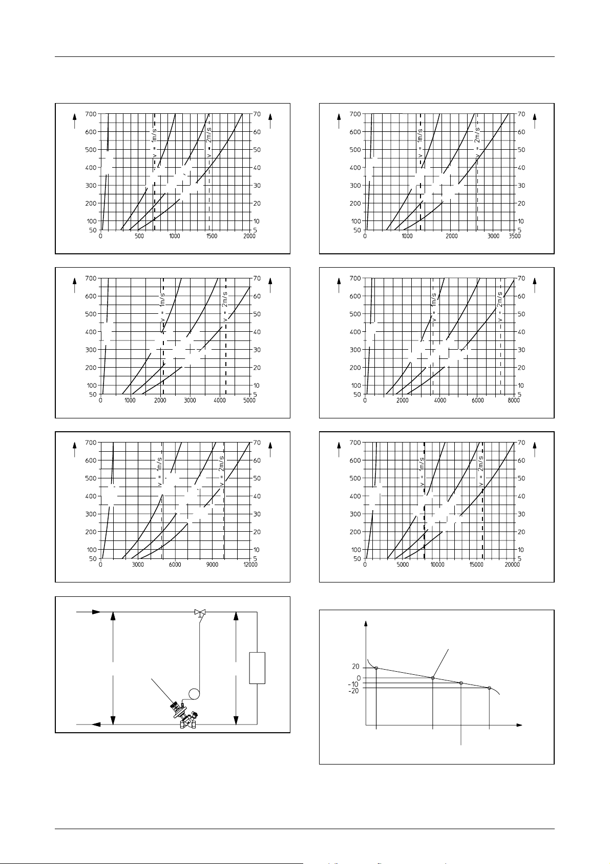
Performance data:
Application range with ∆po ≥ 2 x ∆p
The recommended application range is determined by the minimum flow rate (q
m
min.) and the maximum flow rate (qmmax.).
The design of the regulator can be made with the help of the
above charts. The correct regulator can be determined from the
flow rate and the differential pressure. The maximum flow rate to
be expected in the system may not exceed that of the regulator
(q
m
max.). As for the curve qmnom., the differential pressure of the
system is identical with the set nominal value.
DN 15: kvs = 2.5
Exemple of installation:
Nominal value ∆p [mbar]
Nominal value ∆p[kPa]
DN 20: kvs = 5.0
Lowest P-deviation at medium nominal value setting
(qmnom.).
Nominal value ∆p [mbar]
Nominal value ∆p[kPa]
Supply
Return
System
∆p
0
qmmin. qmmax.qmnom.
q
m
nom.–10%
q
m
∆p
∆p
Nominal value
setting ∆p
Nominal value
setting ∆p
P-deviation [%]
Flow rate qm[kg/h] Flow rate qm[kg/h]
DN 25: kvs = 7.5
Nominal value ∆p [mbar]
Nominal value ∆p[kPa]
DN 32: kvs = 10.0
Nominal value ∆p [mbar]
Nominal value ∆p [kPa]
Flow rate qm[kg/h] Flow rate qm[kg/h]
DN 40: kvs = 15.0
Nominal value ∆p [mbar]
Nominal value ∆p[kPa]
DN 50: kvs = 34.0
Nominal value ∆p [mbar]
Nominal value ∆p[kPa]
Flow rate qm[kg/h] Flow rate qm[kg/h]
The curve q
m
nom. –10% shows the values with a P-deviation of
–10%.
To guarantee a sufficient valve authority of the differential pressure regulator, ∆p should be ≥ 1.5 x ∆p.
Differential pressure regulator “Hydromat DP”
DN 15 to 50
q
m
min.
q
m
nom.
q
m
max.
q
m
nom.–10%
q
m
min.
q
m
nom.
q
m
max.
q
m
nom.–10%
q
m
min.
q
m
nom.
q
m
max.
q
m
nom.–10%
q
m
min.
q
m
nom.
q
m
max.
q
m
nom.–10%
q
m
min.
q
m
nom.
q
m
max.
q
m
nom.–10%
q
m
min.
q
m
nom.
q
m
max.
q
m
nom.–10%
Page 4
2009 Oventrop4
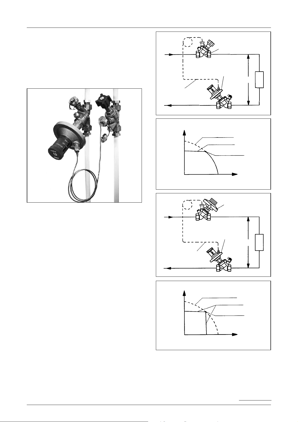
Examples of installation:
“Hydromat DP“ / Isolating valve
Setting and automatic regulation of the differential pressure in a
riser.
Condition:
Calculation of the flow rate and the corresponding differential
pressure of the riser which shall be regulated.
Note:
Simple setting of the desired nominal value by turning the handwheel.
(Illustrated isolating valve is not required for hydronic balancing).
“Hydromat Q“ / “Hydromat DP“
Setting and automatic regulation of the flow rate and the differential pressure in a riser.
Condition:
Calculation must have been made (i.e. total flow rate of the riser
which shall be regulated must be known to find out the correct
size of the valve.)
Note:
Simple setting of the nominal value by turning the handwheel of
the flow regulator and the differential pressure regulator.
Supply
Supply
Return
Return
Capillary
Flow regulator
System
System
∆p
∆p
Design point
Design point
without regulating valves
without regulating valves
with ”Hydromat DP”
with ”Hydromat DP”
with ”Hydromat Q”
∆p
∆p
max.
q
m
qmmax.
Capillary
Differential pressure
regulator
Isolating valve
Differential pressure
regulator
∆p
∆p
max.
q
m
qmmax.
Differential pressure regulator “Hydromat DP”
DN 15 to 50
Subject to technical modification without notice.
Product group 3
ti 96-1/10/MW Printed on paper free from
Edition 2009 chlorine bleaching.
F. W. OVENTROP GmbH & Co. KG
Paul-Oventrop-Straße 1
D-59939 Olsberg, Germany
Telephone +49(0) 2962 82 -0
Te lefax +49(0)2962 82 -450
E-Mail [email protected]
Internet www.oventrop.de
For an overview of our global
presence visit www
.oventrop.de.
 Loading...