

Page 1
Application:
The pressure independent control valve “Cocon QTZ” with automatic flow control is a valve combination consisting of a flow regulator
and a regulating valve. The nominal value of the flow regulator can
be set with the help of an easily accessible handwheel. The pressure
independent valve can be equipped with an actuator, a temperature
controller or a manual head (connection thread M 30 x 1.5).
The pressure independent control valve “Cocon QTZ” is designed
to be installed in heating and cooling systems (e.g. central or underfloor heating systems, fan coil units, chilled ceilings, fan convectors
etc.) with closed circuits for automatic flow control (hydronic
balancing). It can also be used for the control of another variable
(e.g. room temperature) by modifying the flow rate with the help of
actuators, thermostats or temperature controllers.
Technical data:
Performance data
Max. operating temperature: +120°C
Min. operating temperature: -10°C
Max. operating pressure: 16 bar (1600 kPa)
Fluid: Water or mixtures of water and
ethylene/propylene-glycol
(max. 50%), ph-value 6.5-10
Max. closing pressure: 16 bar (1600 kPa)
in the direction of flow
“Cocon QTZ”
Pressure independent control valve
Technical information
“Cocon QTZ”
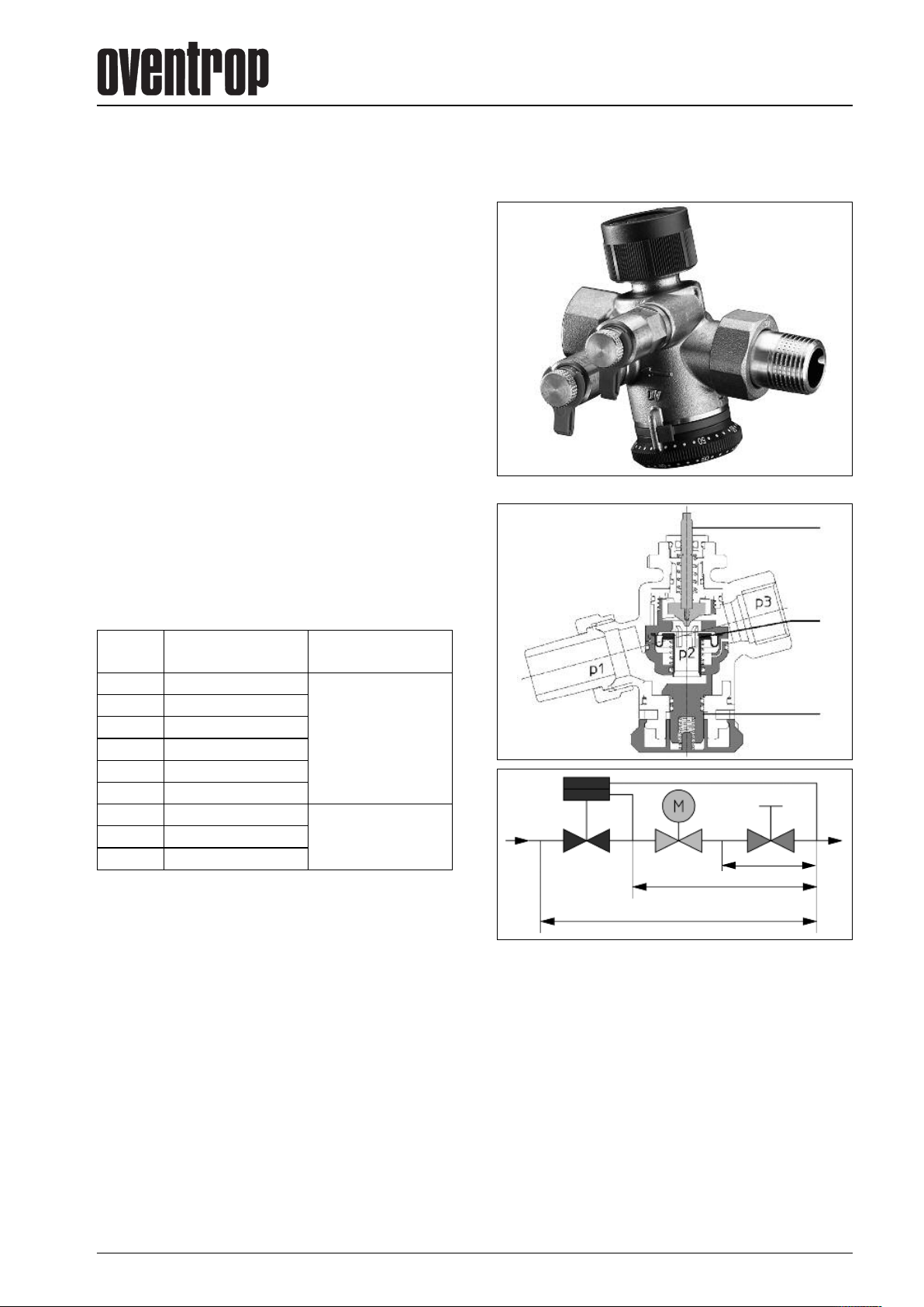
Legend:
1 Flow control unit
1a Diaphragm unit
1b Nominal value unit
2 Control unit
2
Control range:
DN
10
10 90- 450
15 30- 210
15 90- 450
15 150-1050
20 150-1050
20 180-1300
25 300-2000
32 600-3600
Data for actuator connection:
Connection thread: M 30 x 1.5
Piston stroke: 2.8 mm
Closing dimension: 11.8 mm
Closing pressure (actuator): 90 - 150 N
Materials:
Body made of dezincification resistant brass, seals made of
EPDM or PTFE, valve stem made of stainless steel.
Function:
The required flow rate is set at the handwheel (see page 3 at the
bottom). The nominal setting can be secured by engaging the
handwheel and by inserting the locking ring which is lead sealable.
During low demand periods, regulation can be carried out with the
help of an actuator or a temperature controller which can be
screwed onto the valve.
Control range [l/h]
(min.-max.)
30- 210
(DN 10/15/20: 30-1050 l/h)
3.5 mm
(DN 20: 180-1300 l/h)
4 mm
(DN 25 und DN 32)
Differential pressure p1-p
(min.-max.)
0.2 bar-4 bar
(20 kPa-400 kPa)
0.15 bar-4 bar
(15 kPa-400 kPa)
1a
3
1b
p3p2p1
1a 2
p2-p3 = constant
p1-p3
The illustrated section of the pressure independent control valve
“Cocon QTZ” shows three pressure ranges:
“p1” is the inlet pressure and “p3” the outlet pressure of the valve.
“p2” is the pressure actuating the integrated diaphragm unit (pos.
1 a) which maintains the differential pressure “p2” – “p3” at a constant level via the regulating unit (pos. 2) which is activated
through the actuator and via the nominal value unit (pos. 1 b)
which can be set to a maximum flow rate.
Even where high differential pressure variations “p1” – “p3” occur,
e.g. if sections of the system are activated or inactivated, the
differential pressure “p2” – “p3” is kept at a constant level. This
way the valve authorities of 100% are maintained (a = 1). Even
during low demand periods with steady control (e.g. in combination with 0-10 V actuators), the valve authority of the “Cocon
QTZ” valve within the effective valve lift amounts to 100% (a = 1).
∆p
1b
M
2015 Oventrop 1
Page 2
Advantages:
– constant, high valve authority
– small dimensions
– presetting of the nominal values even with mounted actuator
– optical display of the set nominal value even with mounted
actuator
– excellent optical display of the presetting in any installation
position
– nominal values can be read off in l/h without conversion
– presetting is secured by engaging the handwheel
– presetting can be locked and lead sealed with the help of the
locking ring
– installation can be optimised by measuring the regulating
pressure
– almost linear characteristic line if actuator driven
– high valve lift, even with small presetting values
– soft sealing valve disc
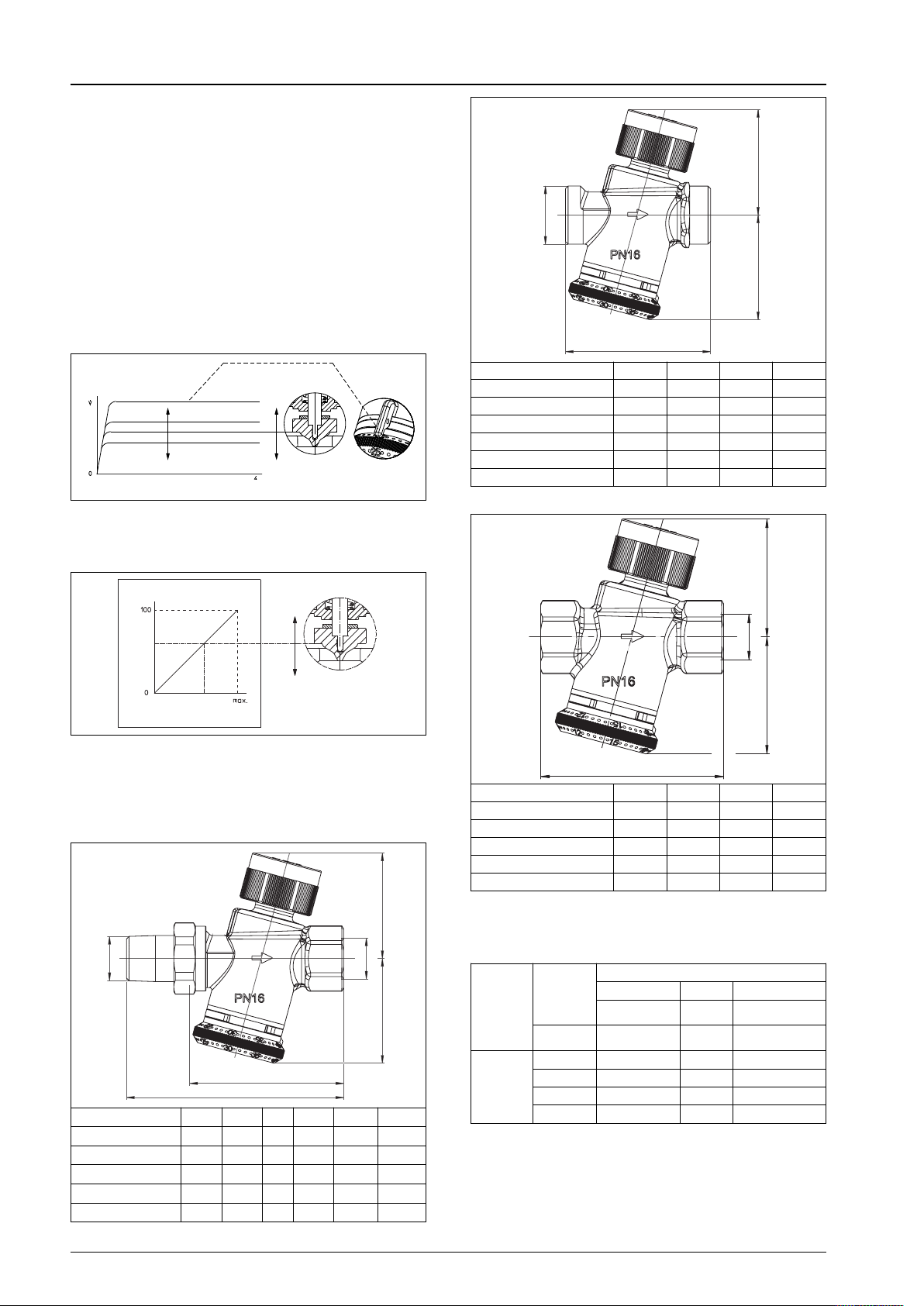
Volume flow [l/h]
Differential pressure p1-p3 [bar]
The maximum flow volume (V) within the control range is set with
·
the help of the handwheel. During low demand periods, room
temperature control may for instance be carried out with the help
of actuators and room thermostats.
“Cocon QTZ”
Pressure independent control valve
D
L1
DN L1 H1 H2 D
10
15 66 52 48 G 3⁄4
20 (150-1050 l/h) 74 52 48 G 1
20 (180-1300 l/h) 84 58 54.5 G 1
25 118 66 79 G 11⁄4
32 124 66 79 G 13⁄4
Dimensions
60 54 46 G 1⁄2
H1
H2
1
H
Effective valve lift [%]
Volume flow [l/h]
The pressure independent control valve “Cocon QTZ” has an
almost linear characteristic line within the effective valve lift. This is
advantageous when using actuators (electrothermal or electromotive) which also have a linear stroke behaviour across the
control voltage. In general, the valve can also be combined with a
temperature controller.
D1
D2
H2 H1
L
1
L2
DN L1 L2 H1 H2 D1 D2
15 70 98.5 52 48 R 1⁄2 Rp 1⁄2
20 (150-1050 l/h) 74 106 52 48 R 3⁄4 Rp 3⁄4
20 (180-1300 l/h) 85.5 117.5 58 54.5 R 3⁄4 Rp 3⁄4
25 118 154 66 79 R 1 Rp 1
32 124 165 66 79 R 11⁄4 Rp 11⁄4
Dimensions
D2
H2
L1
DN L1 H1 H2 D
15 74.5 52 48 Rp 1⁄2
20 (150-1050 l/h) 78 52 48 Rp 3⁄4
20 (180-1300 l/h) 89 58 54.5 Rp 3⁄4
25 122 66 79 Rp 1
32 130 66 79 Rp 11⁄4
Dimensions
Actuators:
The pressure independent control valves “Cocon QTZ” can be
used with the following Oventrop actuators (M 30 x 1.5):
Actuator Voltage
Electrothermal
Electromotive
24V
230V
24V 1012708 1012700/05 (0-10V)
230V 1012710
EIB 1156065/66*
LON 1157065*
1012816/26*
1012916/26
1012815/25/17*
1012915/25
Regulation behaviour
2 point 3 point Proportional
1012951 (0-10V)*
* Actuators with piston strokes smaller than 4 mm. Due to the
smaller piston strokes, the maximum possible flow rates will not
be reached when combining these actuators with valves sized
DN 25 and DN 32.
Item no. 1012703: After modification of the presetting, the
actuator has to be disconnected from the power for a short time.
The “Cocon QTZ” valves can also be used with Oventrop
thermostats and Oventrop temperature controllers.
2 2015 Oventrop
Page 3
“Cocon QTZ”
Pressure independent control valve
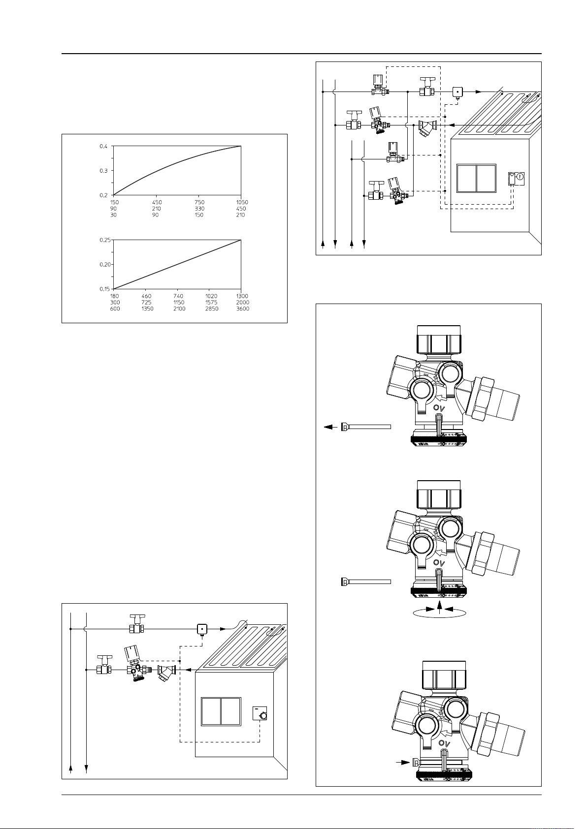
Minimum differential pressure p1 – p3 for the valve design:
The minimum required differential pressure p1 – p3 across the
valve can be obtained for the chart below:
Explanation of chart:
As for the valves with integrated flow control, the required minimum differential pressure changes depending on the nominal setting. The mathematical interrelationship is considered in the chart.
N 10/DN 15/DN 20 (150 l/h-1050 l/h)
D
Min. differential pressure p1-p3 [bar]
N 20 (180 l/h-1300 l/h)/DN 25/DN 32
D
Min. differential pressure p1-p3 [bar]
ominal setting [l/h]
N
ominal setting [l/h]
N
Installation:
– The direction of flow must conform to the arrow on the valve
body.
– The valve may be installed in any position (electric actuators,
except for the actuators 1012915, 1012925, 1012916 and
1012926, may not be installed vertically downwards).
–
Do not use any lubricant or oil when installing the valve as these
may destroy the valve seals. All dirt particles and lubricant or oil
residues must be removed from the pipework by flushing the
latter.
– Any tension applied on the valve by the pipework must be
avoided.
– When choosing the operating fluid, the latest technical
development must be considered (e.g. VDI 2035).
– Isolating valves for maintenance are to be installed in front of
and behind the valve.
– A strainer has to be installed in the supply pipe if the operating
fluid is contaminated (see VDI 2035).
– The correction factors of the manufacturers of the antifreeze
liquids have to be considered when setting the flow rate.
– Once installation is completed, check all installation points for
leaks.
Pipe connection:
– Use suitable compression fittings “Ofix”, tailpipe connection
sets or inserts (when using flat sealing tailpipes) of the Oventrop
product range.
Isolation
Strainer
Control valve
Isolation
Cooling
Heating
Cocon QTZ”
“
ith actuator
w
ew point control
D
oom
R
hermostat
t
System illustration: Four pipe system
Setting of the flow rate:
The maximum flow rate can be set with the help of the protected
presetting at the handwheel.
1. Remove locking ring.
2. Push handwheel and carry out presetting.
Cooling
Isolation
Isolation
“Cocon QTZ”
with actuator
Strainer
Dew point control
Room
thermostat
3. Let handwheel snap back into
the cogs and fit locking ring.
System illustration: Two pipe system
2015 Oventrop 3
Page 4
Pressure test points:
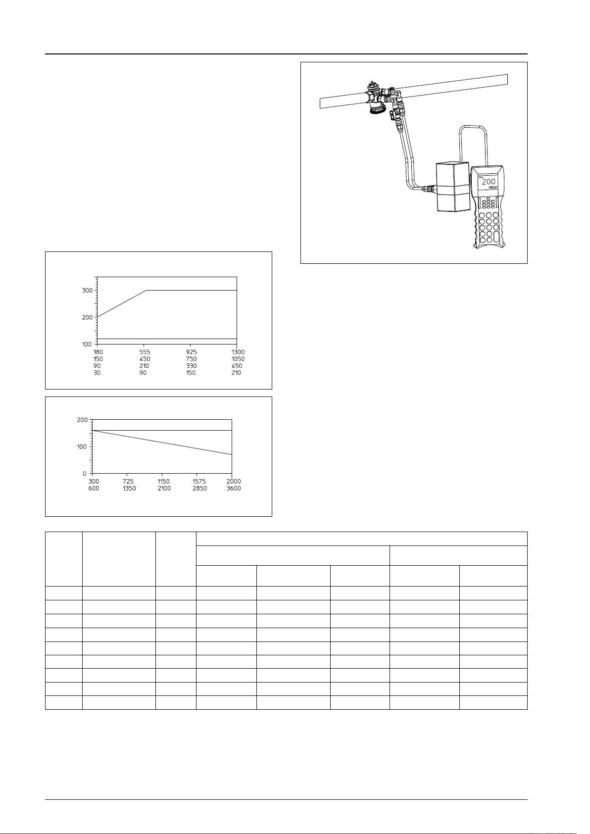
The flow meter “OV-DMC 2” can be connected to the pressure
test points (model “Cocon QTZ” with pressure test points). This
will confirm if the valve is working within the control range. The
pump setting can be optimised by measuring the differential
pressure.
For this purpose, the pump head is reduced until the hydraulically
underprivileged valves are just working within the control range.
As the measured differential pressure is not equal to the minimum
differential pressure (p1 – p3) for the valve design, the following
charts must be used.
With a flow meter connected (e.g. “OV-DMC 2”), the differential
pressure is measured across the flow unit. To do so, the pressure
independent control valve must be fully opened (unscrew
protection cap or set actuator to open position). As soon as
the measured differential pressure is equal or higher than the
differential pressure
within the control range.
∆p
indicated in the chart, the valve works
M
DN 10/DN 15/DN 20 (150 l/h-1050 l/h)
DN 20 (180 l/h-1300 l/h)
[mbar]
M
DN 10/DN 15/DN 20
∆p
Pressure independent control valve
Pressure test points
Maintenance:
The valve has to be serviced if malfunctions occur.
The gland is replaceable under working conditions.
Cocon QTZ”
“
DN 20 (180 l/h-1300 l/h)
Measured differential pressure
Nominal setting [l/h]
DN 25/DN 32
[mbar]
M
∆p
DN 25
DN
32
Nominal setting [l/h]
Measured differential pressure
Item no.
DN
Control range
[l/h]
kvs-
value
without pressure test points
with pressure test points
measuring technique “classic”
male/male female/coupling female/female male/male female/coupling
10 30-210 0.5 1145563 – – 1146063 –
10 90-450 1.1 1145663 – – 1146163 –
15 30-210 0.5 1155564 1145504 1147504 1146064 1146004
15 90-450 1.1 1145664 1145604 1147604 1146164 1146104
15 150-1050 1.8 1145764 1145704 1147704 1146264 1146204
20 150-1050 1.8 1145566 1145506 1147506 1146066 1146006
20 180-1300 2.5 1145666 1145606 1147606 1146166 1146106
25 300-2000 4 1145668 1145608 1147608 1146168 1146108
32 600-3600 7.2 1145670 1145610 1147610 1146170 1146110
Models
4 2015 Oventrop
Page 5
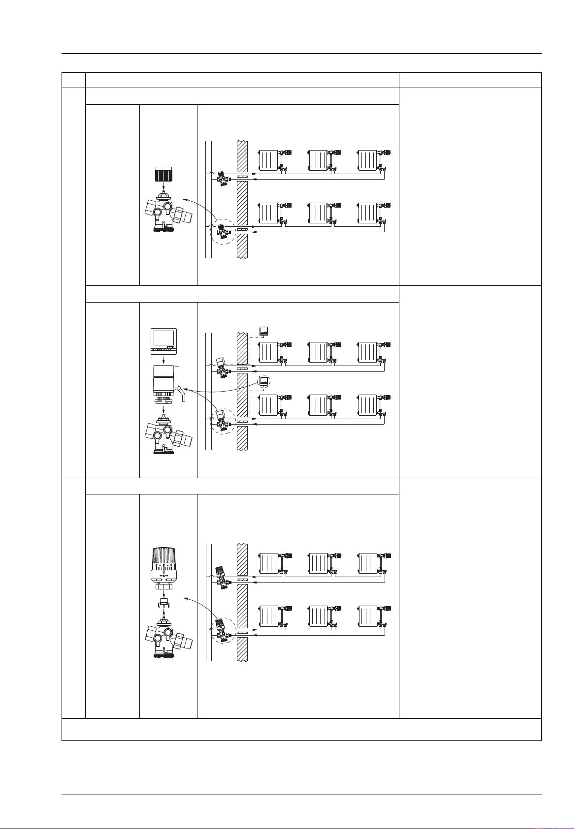
One pipe heating system:
Configuration level of the one pipe heating system Advantages
1a Hydronic balancing of the one pipe heating system
Cap
1146091
+
“Cocon QTZ”
DN 10-DN 32
“Cocon QTZ”
Pressure independent control valve
– Hydronic balancing by
constant volume flows in the
one pipe heating risers
– The risers do not influence
each other
– No undersupply
1b Hydronic balancing + temperature setback of the dwelling unit
Digital
room thermostat
1152561/
1. Constant volume flows for each riser
1152562
+
Actuator
1012915/
1012916
+
“Cocon QTZ”
DN 10-DN 32
2 Hydronic balancing + limitation of return temperature + minimum flow rate
“Uni RTLH”
1149068
+
Distance piece
1149090
+
“Cocon QTZ”
DN 10-DN 32
by limitation of return temperature
2. Variable volume flows for each riser
Rooms supplied by the riser must belong
to one dwelling unit!
– Hydronic balancing by
constant volume flows in the
one pipe heating risers
– The risers do not influence
each other
– No undersupply
+
– Additional energy savings
by reduction of the volume
flow and reduction of
the heat loss during low
demand periods, e.g. night
setback
– Daily and weekly setback
periods programmable via
a digital room thermostat
– Hydronic balancing by
constant volume flows in the
one pipe heating risers
– The risers do not influence
each other
– No undersupply
+
– Energy savings by limitation
of the return temperature
– Room temperature control
is improved by the reduction
of the volume flow during
low demand periods as
overheating is avoided
– Quick reactivation after
reduction to a minimum volume
flow which is guaranteed
by the distance piece
– Low return temperatures
(important for gross calorific
appliances and district
heating systems)
To be observed: The “Cocon QTZ” valves should not be installed in rooms which are sensitive to noise.
2015 Oventrop 5
Page 6
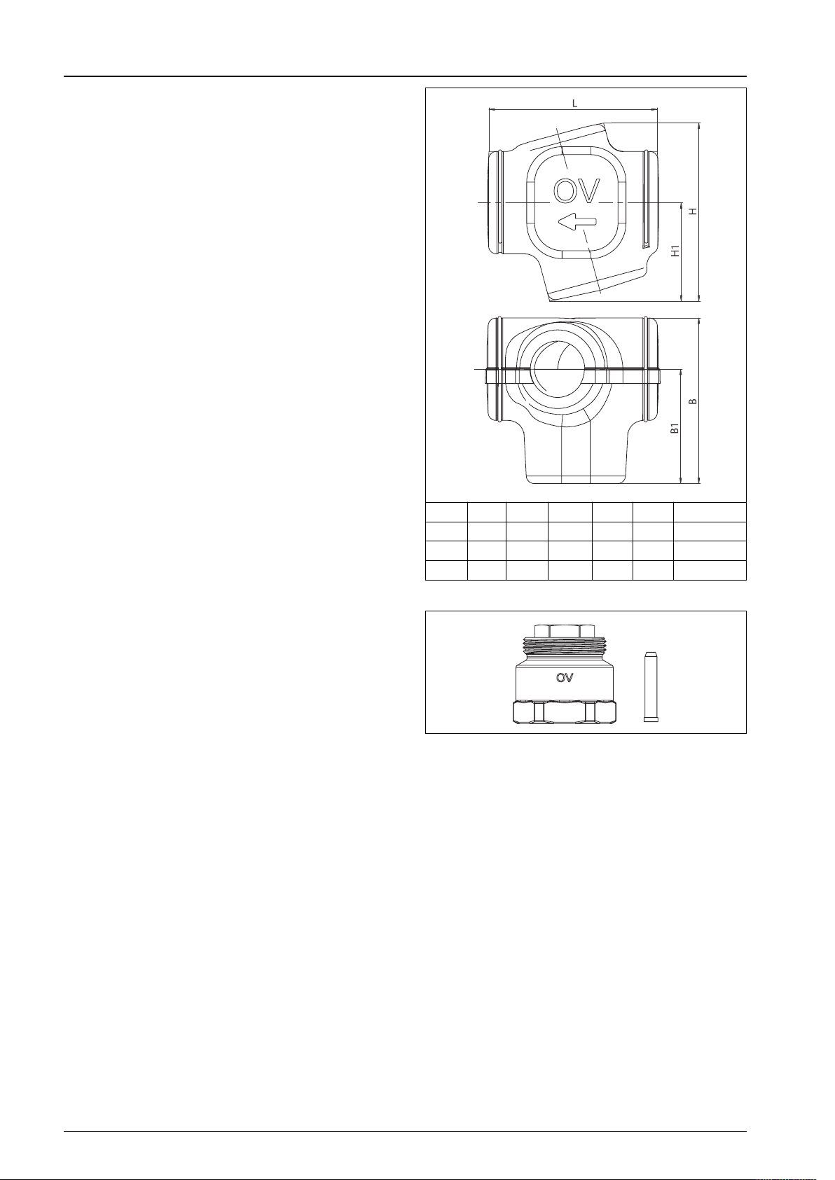
Insulation shells DN 15 – DN 32
Tender specification:
The insulation shells have a CFC-free inner core made of
polyurethane rigid foam with a 1.5 mm plastic coat.
They consist of two double shells which are tightened by two
metal straps.
For heating and cooling systems.
Building material class B2 according to DIN 4102.
Operating temperature t
: -20°C up to +130°C
s
Sizes: Item no.:
DN 15 – DN 20 1149104
DN 20, model 180 – 1300 l/h 1149106
DN 25 – DN 32 1149108
Accessories:
Adapter with stem for “Cocon QTZ” 1149190
Extension = 25 mm
Is required if the “Cocon QTZ” valves shall be equipped with
insulation shells and actuators.
“Cocon QTZ”
Pressure independent control valve
OVENTROP GmbH & Co. KG
Paul-Oventrop-Straße 1
D-59939 Olsberg
Germany
Telephone +49(0)2962 82-0
Fax +49(0)2962 82- 450
E-Mail [email protected]
Internet www.oventrop.de
DN L H H1 B B1 Item no.:
15/20 106 112 62 105 72 1149104
20* 116 125 69 120 82 1149106
25/32 166 169 101 154 97 1199108
Dimensions – *Model: 180 – 1300 l/h
Adapter with stem
For an overview of our global presence
visit www.oventrop.de
Subject to technical modification without notice
Product range 3 Gedruckt auf chlorfrei
ti 218-EN/10/MW
Edition 2015 gebleichtem Papier.
6 2015 Oventrop
 Loading...