

Ovation Systems Gemini 2, Gemini 4 User Manual

Issue 1.1 Ovation Systems Ltd. Page 1
www.ovation.co.uk
Gemini-4
User Guide
Video Link Expander
Gemini 2 & 4
Video Link Expander
User Guide
Ovation Systems Ltd.
Great Haseley Trading Estate
Great Haseley
Oxfordshire
OX44 7PF
UK
Tel: +44 1844 279 638
Fax: +44 1844 279 071
Email: support@ovation.co.uk
Web: www.ovation.co.uk
Issue 1.1 Ovation Systems Ltd. Page 2
www.ovation.co.uk
Gemini-4
User Guide
Video Link Expander
1 Introduction
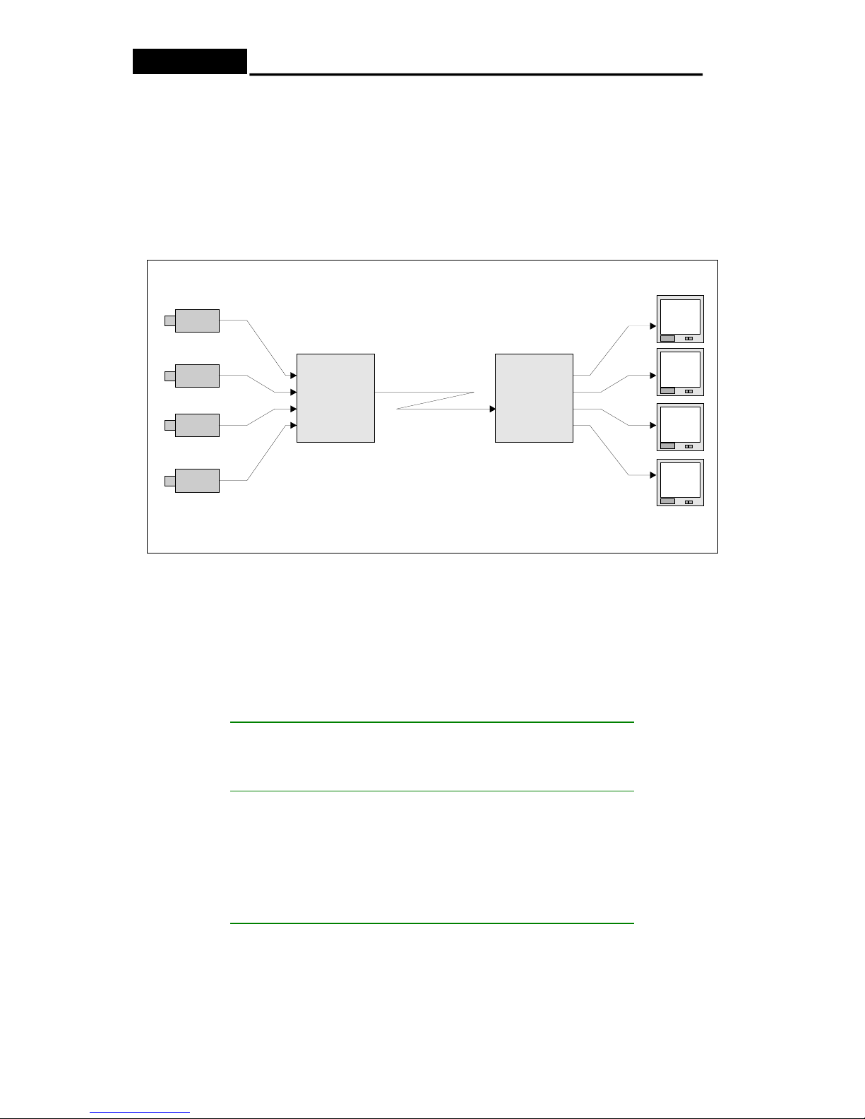
Gemini-4 allows extra cameras to be easily sent over an existing video surveillance link
without the need of any modification. Gemini operates by multiplexing up to 4 video inputs
together into one video stream suitable for transmission over a coax, fibre-optic or RF/
microwave link. At the receive site, the Gemini decoder splits the multiplexed stream back
into separate outputs ready to be viewed on individual monitors, or a combination of scaled
pictures on one monitor, as required. See Figure 1: Gemini Application Diagram.
Gemini
Decoder
Gemini
Encoder
Camera 1
Camera 2
Camera 3
Camera 4
TV
1
TV
3
TV
2
TV
4
Any real-time
video link
- Coax
- Fibreoptic
- RF
Figure 1: Gemini Application Diagram.
Gemini provides the fastest possible picture update rates by using video field multiplexing.
The picture update rate per channel is dependant upon the number of active inputs to the
encoder and the video standard used. Please refer to Table 1 below showing details of
Gemini’s update rates:
Number
of
Inputs
PAL Picture Update
Rate
(Pictures per Second)
NTSC Picture Update
Rate
(Pictures per Second)
1 50 60
2 25 / 25 30 / 30
3 25 / 12.5 / 12.5 30 / 15 / 15
4 12.5 / 12.5 / 12.5 / 12.5 15 / 15 / 15 / 15
Table 1: Gemini Picture Update Rates
Issue 1.1 Ovation Systems Ltd. Page 3
www.ovation.co.uk
Gemini-4
User Guide
Video Link Expander
2 Quick Start Guide
The Gemini system is supplied as an encoder / decoder pair with DC power leads. The
following describes the basic installation:
2.1 Ensure the units are configured for the correct video standard (PAL or NTSC). A “PAL”
or “NTSC” label on the side of the unit indicates the configuration.
2.2 Ensure the encoder’s and decoder’s mode control switches are both set to “0” as
shown in Figure 2.
2.3 Connect 7 to 32 V DC power source to the encoder and decoder to units using Lemo
cable assembly provided, as shown in Figure 2. As a guide the encoder requires
approximately 300 mA, the decoder 400 mA, at 12 Volts DC.
Red
+ 6 to
32 V
DC
Blue
0 V
Video
Expansion port
& RS232
Mode
Control
Switch
DC Power
0
1
9
2
A
3
B
4
C
5
D
6
E
7
F
8
Figure 2: Gemini Interfaces / User Control
2.4 Connect up to 4 video sources (cameras) to the encoder’s video inputs. Any
combination of input channels may be used. All video connections are nominally 1 V pp
with 75Ω terminations.
2.5 Connect the encoder’s video output to the real-time video link (see Figure 1).
2.6 Connect the output of the video link to the decoder’s input (see Figure 1).
2.7 Connect the number of video monitors required to the Gemini decoder’s outputs (see
Figure 1).
 Loading...