

Oval TF1015-P11G-11 A, TF1050-A12G-11 A, TF1020-P11G-11 A, TF1025-A12G-11 A, TF1040-A12G-11 A Instructions Manual

MASS FLOW MONITOR
Ins. No.
S-193-11-E
MODEL:TF10□□-
P11
G- 11□A□
A12
TF1025-A12G-11□A□
TF1015-P11G-11□A□
TF1020-P11G-11□A□
Every OVAL
control.
In order to maintain its design performance throughout its life, this manual offers the operator the necessary
installation, operation and maintenance information.
Be well familiar with these instructions before you place the product in service and keep this manual at the
field location for ready reference.
Mass Flow Monitor
is fabricated and shipped from our factory under stringent quality
TF1040-A12G-11□A□
TF1050-A12G-11□A□
1

S-193-11-E
CONTENTS
1. BEFORE YOU BIGIN ............................. 3
1.1 Confirming the Nameplate ......................... 3
1.2 Transportation Considerations ................... 3
1.3 Storage Considerations .............................. 3
2. OPERATING CONDITIONS ...................4
3. GENERAL ..............................................
3.1 Features ...................................................... 4
4. COMPONENT NAMES AND
FUNCTIONS .......................................... 5
4.1 Part Names ................................................. 5
4.2 Individual Functions ................................... 5
5. INSTALLATION ...................................... 6
5.1 Installation Location .................................... 6
5.2 Physical Orientation ................................... 6
5.3 How to Change Display Orientation ........... 6
5.4 Conditions Required for Metered Fluid ...... 8
5.5 Tubing Guidelines ....................................... 8
5.6 Maximum Service Flowrate ........................ 9
7. OPERATION ........................................ 14
8. TRANSMITTER DISPLAY FUNCTIONS
AND RECONFIGURATION .................. 15
8.1 Viewing the Flow Variables ........................15
8.2 Parameter Display .....................................16
4
8.3 Default Parameter Settings .......................18
8.4 Parameter Reconfiguration .......................19
8.5 Alarm Features .........................................20
8.6 Dummy Pulse Output ................................24
8.7 Analog Output Trim ...................................25
8.7.1 Analog Trim (4mA) ....................................... 25
8.7.2 Analog Trim (20mA) ..................................... 26
8.8 Error Messages .........................................27
9. GENERAL SPECIFICATIONS ............. 28
10. APPLICABLE STANDARDS ..............28
11. PRODUCT CODE EXPLANATION .... 29
12. OUTLINE DIMENSIONS ....................30
6. WIRING CONNECTIONS ..................... 10
6.1 Wiring Specifications .................................10
6.2 Wiring Diagram ..........................................10
6.3 Cable Specifications .................................14
CONVENTIONS
Shown in this manual are the signal words NOTE, CAUTION and WARNING, as
described in the examples below:
NOTE: Notes are separated from the general text to bring the user's attention
to important information.
CAUTION: Caution statements signal the user about hazards or unsafe practices
which could result in minor personal injury or product or property
damage.
WARNING: Warning statements signal the user about hazards or unsafe practices
which could result in severe personal injury or death.
2
S-193-11-E
1. BEFORE YOU BIGIN
Every OVAL product is thoroughly inspected and tested before it leaves the factory. When received, it should
be thoroughly inspected for indication of rough handling during transit. Necessary handling precautions are
described in this section; read the instructions carefully.
As for other information, find the respective sections from "CONTENSTS" on page 2.
For any inquiries, contact your nearest OVAL designated sales office.
CAUTION:
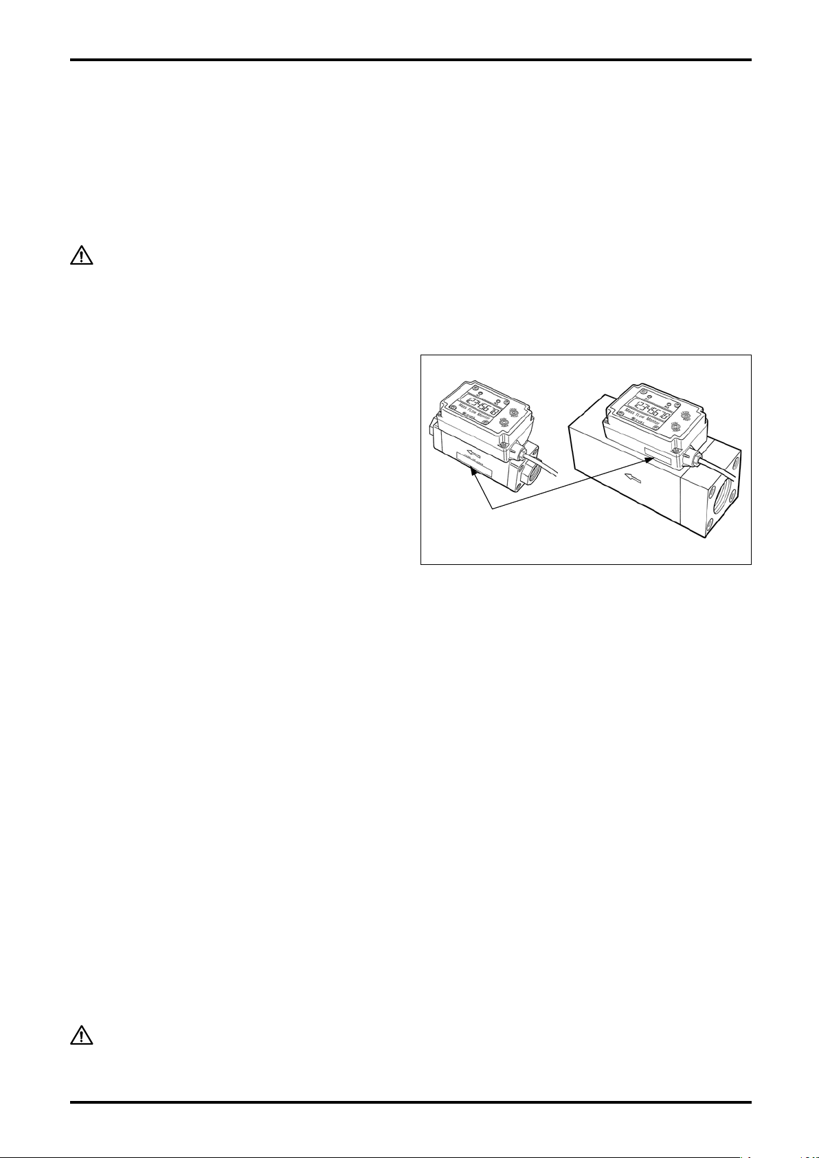
1.1 Confirming the Nameplate
Ev e r y O VAL m o n i tor is carefull y a s s e m b l e d a n d
accurately adjusted to first-class condition. Product
code number and ratings appear on the nameplate. By
referring to the general specifications in Section 9 and
product code explanation in Section 11, make sure
that the product you received is fully in compliance
with your order.
When you make inquiries, include the product name, model number, stock
number, ratings and other pertinent information.
Nameplate
(ratings shown)
1.2 Transportation Considerations
(1) It is desirable that the monitor be transported to the installation site in the shipping container used for
transit from the factory.
(2) During transportation, exercise care to avoid impact shock and rainwater.
1.3 Storage Considerations
Storing your mass flow monitor for long periods of time upon receipt before installation can result in
un exp ecte d and undes irab le conditions . Whe n long -term storage is anti cipa ted, take th e following
precautions:
(1) The monitor can best be stored in the shipping container used for transit from the factory.
(2) Select the storage place that meets the following requirements:
★ free from rain and water
★ free from vibration and impact shocks
★ with least temperature and humidity variation (around 25°C and 65% R.H).
(3) A monitor that has once been placed in service for any length of time should be washed clean to remove
residue of metered material completely from its main body, joint, conduit, and outer case before storage.
Especially, purge the inner wall of flow path with clean air or nitrogen gas, and then protect the flow inlet
and flow outlet against entry of dust inside.
CAUTION:
1. At cleansing, do not use solvents, such as thinner and alcohol.
2. Never attempt to cleanse the interior flow path with detergent.
3
S-193-11-E
2. OPERATING CONDITIONS
The monitor operating conditions are stated on the specification label, Section 5 "INSTALLATION" and Section
9 "GENERAL SPECIFICATIONS." Read carefully before initiating operation.
CAUTION:
This monitor is of non-explosionproof configuration; it is not serviceable in a
hazardous location.
3. GENERAL
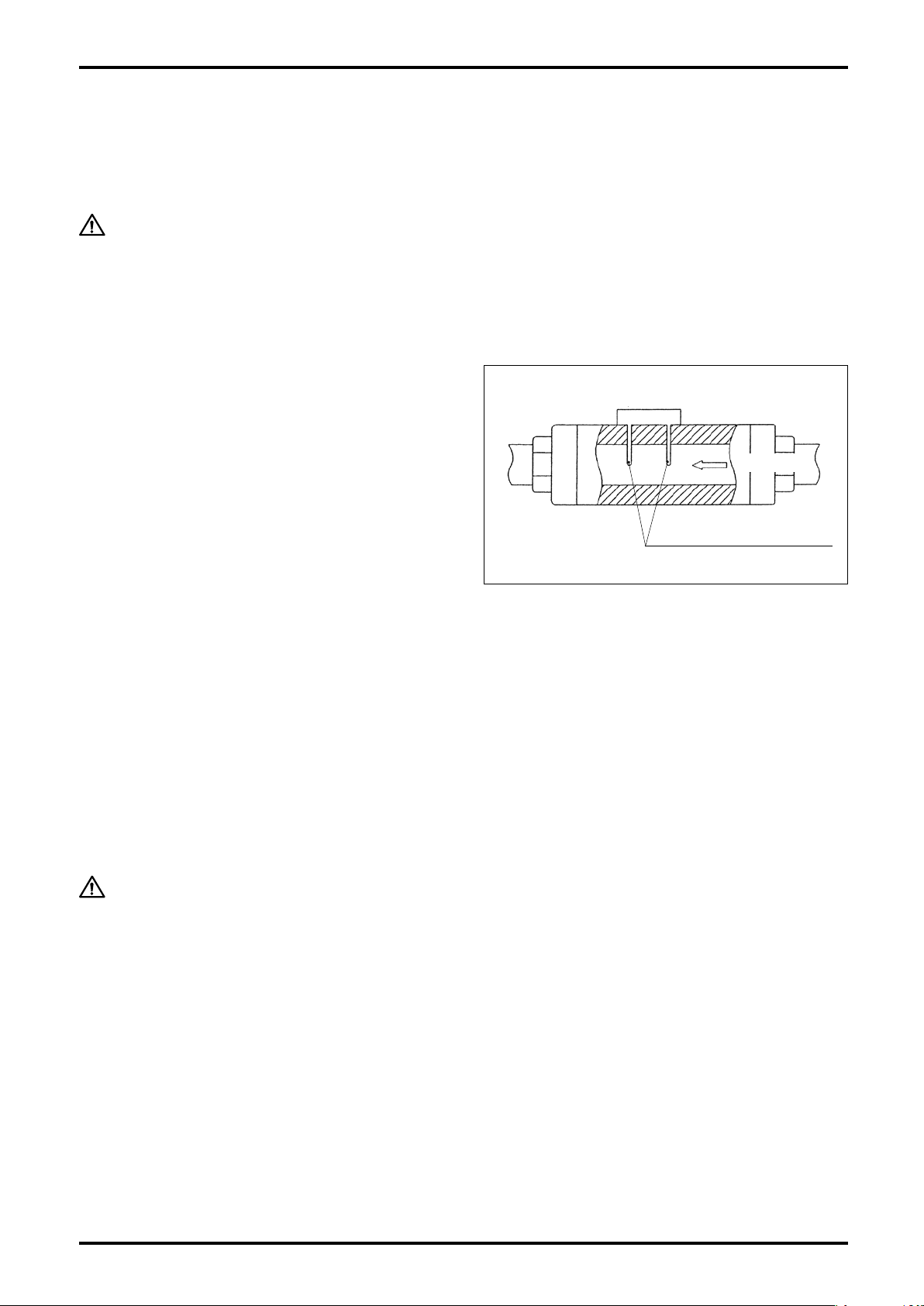
This monitor is a small, lightweight flowmeter, using a
heat-sensitive resistance element.
Of the two heat-sensitive resistance elements located
perpendicular to the fluid flow; one detects the fluid
temperature and the other, which plays the rol e of
a heater, regulates the temperature of the former to
maintain a constant temperature differential. As the
flow ing process f l uid (ma s s f low) d i s sipate s h e at
from the latter which ser ves as a heater, its supply
power increases in order to maintain the temperature
differential. This change in power consumption (voltage
and current) is used to calculate the mass flowrate.
Heat-sensitive
resistance elements
Fig. 3.1
Flow direction
3.1 Features
(1) Absence of moving parts contributes to long life.
(2) Major components are made of synthetic resin. Lightweight and compact.
(3) Sturdy metallic couplings.
(4) The display is a backlit LCD for readability in darkness.
(5) May be installed in any position. The display can be oriented in 90 deg steps to see easily.
CAUTION:
Adjusting the display orientation requires opening the upper case of transmitter.
The procedure to change orientation appears in Section 5.3 "How to Change
Display Orientation".
4

4. COMPONENT NAMES AND FUNCTIONS
4.1 Part Names
S-193-11-E
LCD display
(Unit indicator)
③ Transmitter
② Sensor
Alarm 1 LED
Alarm 2 LED
⑤ RESET button
④ MODE button
Screw
connection
Flow direction
① Monitor body
Mounting hardware (option)
Fig. 4.1
4.2 Individual Functions
No. Part Name Description
① Body Consists of a measuring tube, straightener, and rectification mesh.
Consists of two heat-sensitive resistance elements. Power supply (voltage and current)
② Sensor
③ Transmitter
④ Mode button Changes display modes to the instant flowrate or total flow. (See Sec. 8.1 for details.)
⑤ Reset button Used to reset the "Resettable total flow" to zero.
CAUTION:
to one of the heat-resistive resistance elements changes to maintain the heat resistance at a constant level (approx. 30°C).
Changes in supply power (voltage and current) are transformed into a flowrate signal
which can be monitored on a 8-digit LCD display in terms of instant flowrate and total
flow.
Do not attempt to disassemble the meter. If the flow path is badly contaminated
or a malfunction is suspected, contact the nearest customer service network in
your area. Unauthorized disassembly will void the warranty.
5

S-193-11-E
5. INSTALLATION
5.1 Installation Location
This monitor is for indoor use.
Select an installation location that meets the requirements set forth below.
CAUTION:
(1) Free from rain and water.
(2) Least temperature variation.
(3) Free from direct exposure to the sun.
(4) Least vibration and impact shock.
(5) Easy to read the display and accessible for servicing.
(6) Process condition to keep fluid pressure not to exceed the permissible pressure of 0.7 MPa.
5.2 Physical Orientation
This monitor is NOT serviceable in a hazardous location.
There is no restriction on physical orientation of the monitor to cause loss of the accuracy.
Make sure that the actual flow direction conforms to the flow direction arrow indicated on the monitor body.
NOTE: The display orientation can be adjusted in 90 deg steps to see easily (see Section 5.3).
5.3 How to Change Display Orientation
This work is done with the transmitter subassembly removed. Observe the following instructions:
(1) Work in a clean environment before installing the monitor in the tubing system.
(2) Avoid working in a moist or dusty environment.
(3) Exercise care to avoid damaging the components on the electronics substrate while you work.
Required tools: Screwdrivers (for M3 and M2.6 cross recess pan head screws).
Display orientation is adjustable in 90 deg steps as shown below:
90° to the left
Standard
(at shipment from factory)
90° to the right
180°
Flow Direction
Fig. 5.1
6
S-193-11-E
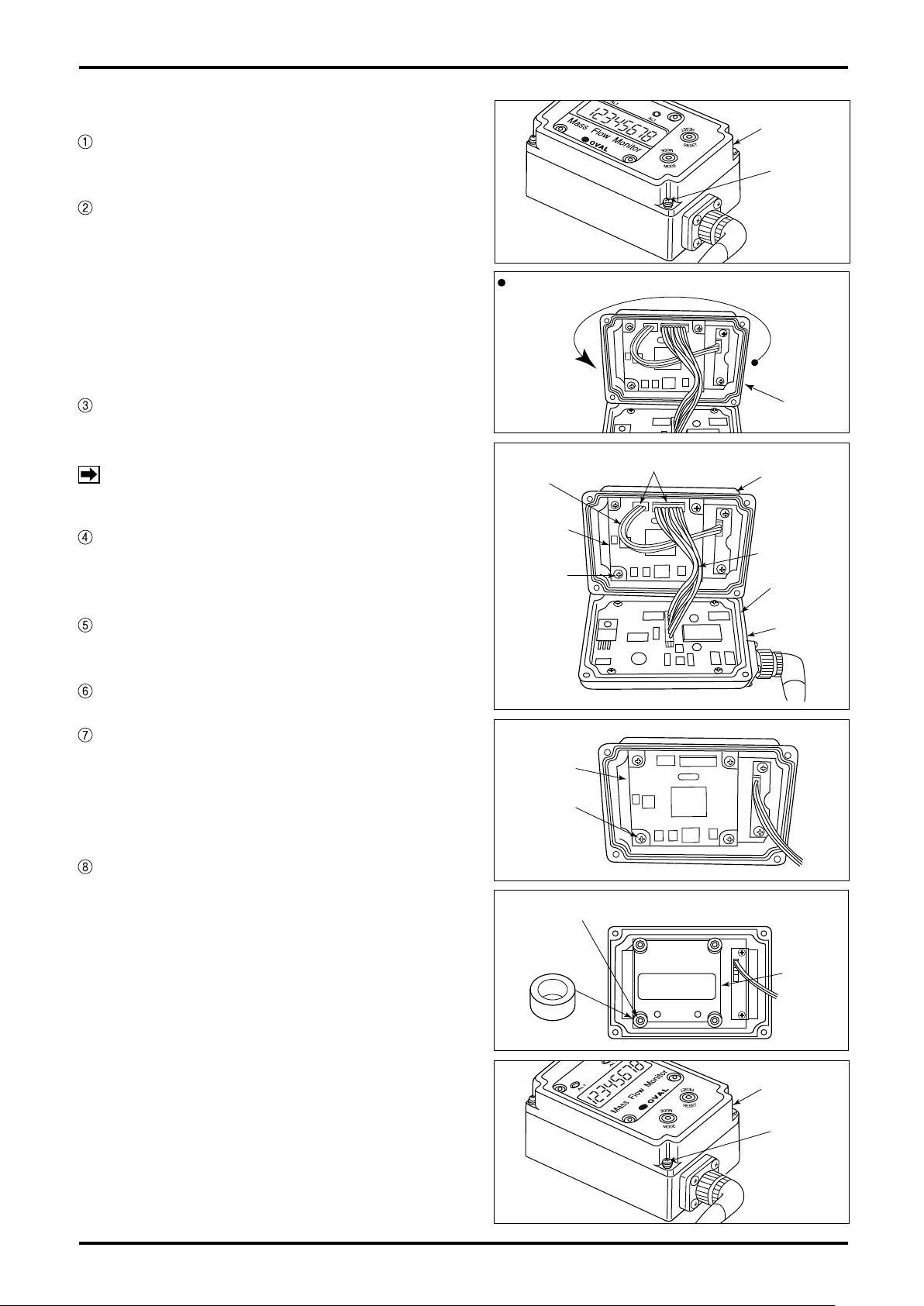
How to Change Display Orientation
If power is supplied, shut it off. (Make sure
nothing appears on the LCD).
Take off four set screws (3×14) securing the
upper case to the transmitter and carefully
open the upper case (Fig. 5.2).
If a 180 deg. turn is your option, turn the upper
case the other way with lead wires intact (Fig.
5.3).
To turn 90 deg. clockwise or counterclockwise
follow the steps given below.
Take off four set screws (2.6×8) holding the
display board in place and remove the display
board (Fig. 5.5).
NOTE:
Remove four spacers (white rings) attached to
the bosses that have secured the display board
in place (Fig. 5.6).
Do not take out the screws fixing amp
board on lower case in any case.
Upper Case
Setscrew
(4 PLC'S)
Fig. 5.2
Turn the upper case 180°, with cables intact.
Upper
Fig. 5.3
Cable Connectors
3-wire
Cable
Display
Board
Setscrew
(4 PLC'S)
Case
Upper Case
10-wire Cable
O-Ring
Extract the top panel and put it onto the upper
case then in the different orientation.
Install the removed spacers over the bosses.
Place the display board in line with the top
panel and secure it with four screws (2.6×8
with tightening torque 45cN・m). (Align the
opening in the top panel with the mating LED
on the display board).
Make certain that O-ring fits in the groove
of lower case and, exercising care against
pinched cables, secure the upper case with
four screws (3×14 with tightening torque of
60cN・m). Tighten them in an alternating order
to ensure even tightening (Figs. 5.7).
Fig. 5.4
Display
Board
Setscrew
(4 PLC'S)
Fig. 5.5
Bosses (4 PLC'S)
Spacer
(4 PLC'S)
Fig. 5.6
Lower
Case
Top Panel
Fig. 5.7
Upper Case
Setscrew
(4 PLC'S)
7
S-193-11-E
5.4 Conditions Required for Metered Fluid
Due to the fact that this monitor is a thermal flowmeter, contamination buildup can cause loss of accuracy. In
an environment where entrapment of contaminants, such as dust, oil, and water, is anticipated, it is a good
practice to provide a filter, drain, separator or similar arrangement upstream of the monitor.
5.5 Tubing Guidelines
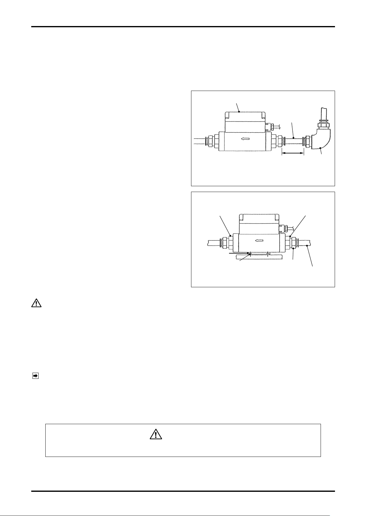
(1) Required Tubing Conditions
Since the monitor has a built-in straightener,
tubing conditions, such as differences in tube
diameter, for example, rarely present a problem.
However, if an elbow is to be located upstream
of the monitor, provide a straight tube about the
length of a nipple (3D min.). Direct installation of
an elbow may possibly cause an error of ±1 %
F.S. or so.
There is no restriction on tubing arrangements
downstream of the monitor.
(2) Installation of mounting hardware (option for
meter sizes 15mm and 20mm).
Required tool: Torque screwdriver that fits M3
cross recess pan head screws.
Do not use any other accessories except for the
furnished dedicated screws (tap-tight screws
3 x 8). See outline dimensions in Sec. 12 for
Installation location and orientation.
Torque specification: 60±3 cN・m
Meter Fitting
Meter fitting
Monitor body
Screw
Straight tube
30 min.
D: Meter I.D.
Fig. 5.8
Mtg. Hardware
Quick-connect coupling
Synthetic resin tube
Fig. 5.9
Elbow
CAUTION:
With metal tubes, tubing stresses could damage the flowmeter at its metal
fittings. Do not use the mounting hardware with metal tubes. Instead, secure
the metal tubes with U-bolts or similar fittings.
(3) Tube Connection Procedure (for meter sizes 15mm and 20mm)
1. Connecting parts are of aluminum die casting: avoid forcibly installing them and giving an impact
shock. The monitor body is of synthetic resin: avoid applying stresses on it. Torque specification: 30 ±
1 (N・m)
NOTE: Hold the hexagonal flats of aluminum die cast connection firmly with wrench, or similar tool, when
you work (Fig. 5.9).
2. Use care to safeguard the transmitter from coming in contact with tools, such as wrench.
3. Do not hold the transmitter by force while connecting it to the tubing system.
4. Providing a union before and after the flowmeter is suggested to facilitate flowmeter removal.
WARNING
Negligence of the precautions above may result in damaged components.
(4) Flushing
If foreign solids are expected to get into the tubing system, particularly on a new installation, flushing of
the tubing assembly thoroughly is essential before installing the monitor.
8
S-193-11-E
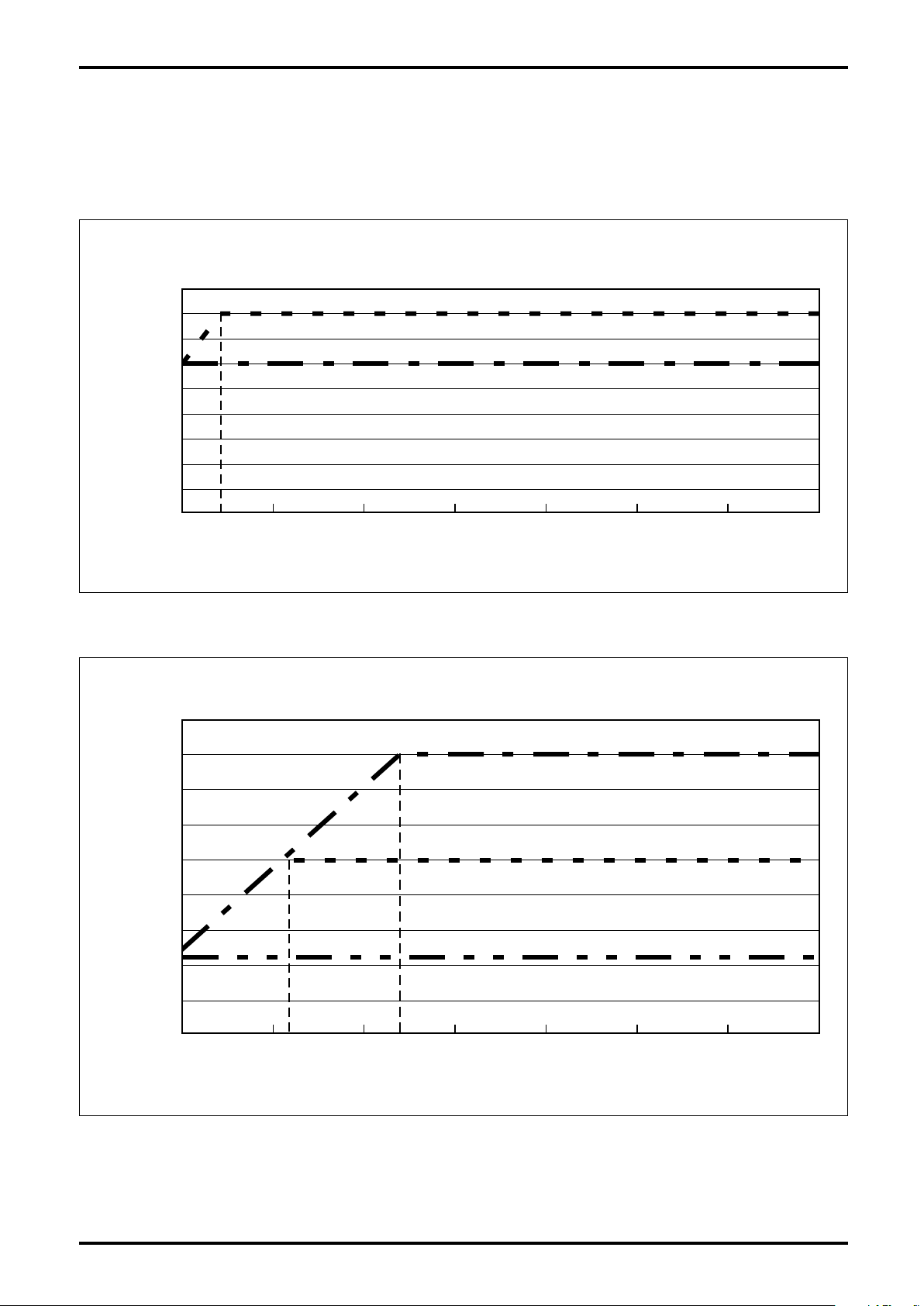
9000
8000
7000
6000
5000
4000
3000
2400
2200
2000
1000
0
0 0.1 0.2 0.3 0.4 0.5 0.6 0.7
0.240.11
Line pressure [MPa]
Max. service flowrate [L/min (normal)]
Nominal size 40 mm
Nominal size 50 mm
Nominal size 25 mm
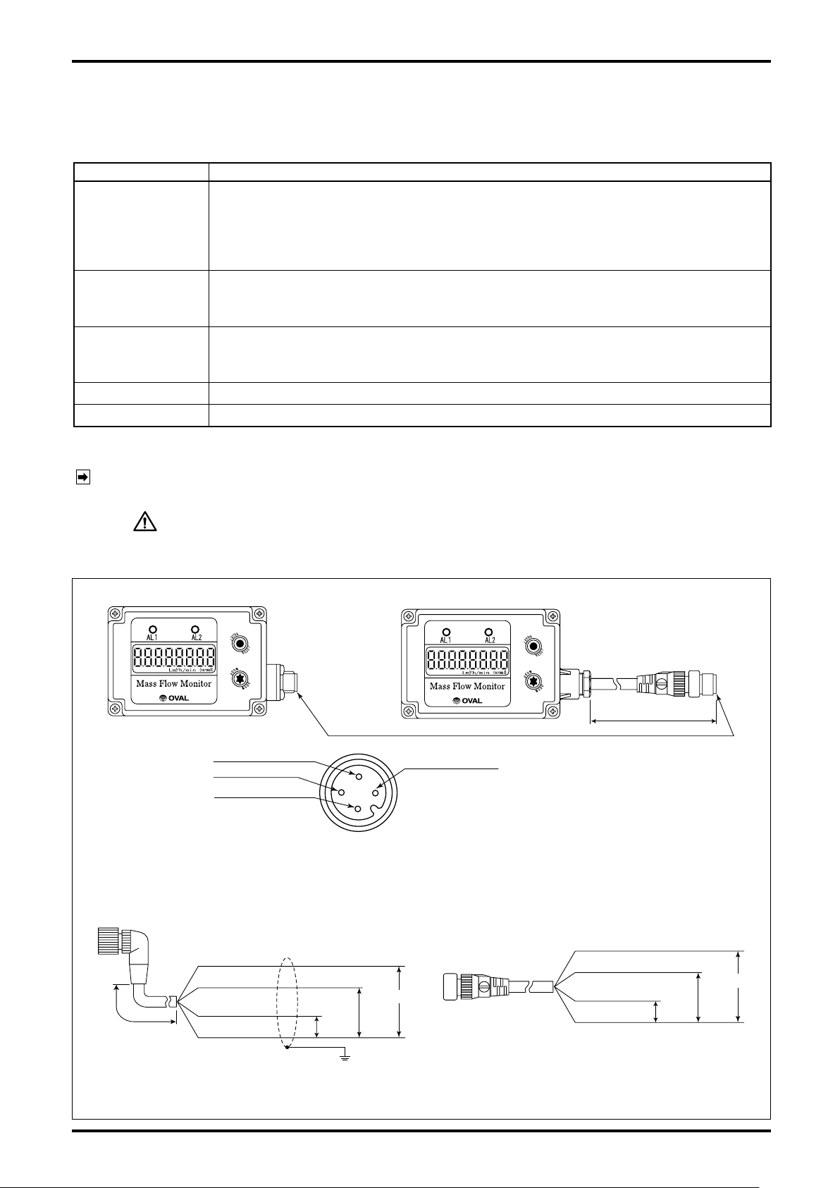
900
800
700
600
500
400
300
200
100
0
0 0.1 0.2 0.3 0.4 0.5 06 0.7
0.04
Line pressure [MPa]
Max. service flowrate [L/min (normal)]
Nominal size 20 mm
Nominal size 15 mm
5.6 Maximum Service Flowrate
The maximum service flowrate varies with line pressure. Measurement continuation at larger service flowrates
may possibly damage the sensor. Therefore, determine the maximum service flowrate from the following
graphs and place the sensor in service within the rate so obtained.
■ Line pressure vs. maximum service flowrate (nominal sizes 15mm and 20mm)
■ Line pressure vs. maximum service flowrate (nominal sizes 25mm, 40 and 50mm)
9
S-193-11-E
1: SUP (power +)
4: Flow pulse output
3: COM (power-)
GND
Shieldedwire
ConnecttheshieldedwiretoGND.
BRN:SUP(power+)
WHT:Alarm1output
YEL:Flowpulseoutput
GRN:COM(power-)
max.
30VDC,
20mADC
max.
30VDC,
20mADC
24VDC±10%
BRN:SUP(power+)
2: Alarm 1 output
Connector terminal
1
3
4
2
WHT:Alarm1output
BLK:Flowpulseoutput
BLU:COM(power-)
max.
30VDC,
20mADC
max.
30VDC,
20mADC
24VDC±10%
●Cable (OMRON)
●Cable (OVAL)
Model: XS2F-D42□-□80-F
Note: For cables, refer to the following figures.
• When product code "Output terminal" is [2] or [4], OVAL cable is supplied.
• When product code "Output terminal" is [3] or [5], cable must be prepared by the customer.
In this case, OMRON cable is recommended.
25 cm
3m
6. WIRING CONNECTIONS
6.1 Wiring Specifications
Table 6.1
Item Description
The following cables are supplied depending on the 15th digit of the product code.
Transmission cable
(Depends on your
specification).
[1]: 5-conductor shielded cable of 3 meters long (O.D.: 6.3mm) ... Fixed to this
unit.
[2][4]: 4-conductor shielded cable of 3 meters long (O.D.: 6.3mm, 4-pin connector is
provided at the one side of the cable) ... Supplied with this unit.
Open collector output
Alarm output
Allowable current: 20mADC
Max. voltage impression: 30VDC
Open collector output
Flow pulse output
Allowable current: 20mADC
Max. voltage impression: 30VDC
Flow analog output 4 to 20mA corresponding to 0 to F.S.
Supply Voltage 24VDC±10%
6.2 Wiring Diagram
NOTE: For output terminal types and styles, see "Explanation of Output Terminal Types" below NOTES in
Sec. 11.
CAUTION:
1. Use extra care about the polarities of power source.
2. Do not fail to earth ground the shielded wire to GND.
(1) Flow pulse output + single alarm point specifications (Fig. 6.1)
● Connector terminal
● Connector via interconnect cable
10
Fig. 6.1
 Loading...