

Oval TF1015-P11G-11 A, TF1050-A12G-11 A, TF1020-P11G-11 A, TF1025-A12G-11 A, TF1040-A12G-11 A Instructions Manual

MASS FLOW MONITOR
Ins. No.
S-193-11-E
MODEL:TF10□□-
P11
G- 11□A□
A12
TF1025-A12G-11□A□
TF1015-P11G-11□A□
TF1020-P11G-11□A□
Every OVAL
control.
In order to maintain its design performance throughout its life, this manual offers the operator the necessary
installation, operation and maintenance information.
Be well familiar with these instructions before you place the product in service and keep this manual at the
field location for ready reference.
Mass Flow Monitor
is fabricated and shipped from our factory under stringent quality
TF1040-A12G-11□A□
TF1050-A12G-11□A□
1

S-193-11-E
CONTENTS
1. BEFORE YOU BIGIN ............................. 3
1.1 Confirming the Nameplate ......................... 3
1.2 Transportation Considerations ................... 3
1.3 Storage Considerations .............................. 3
2. OPERATING CONDITIONS ...................4
3. GENERAL ..............................................
3.1 Features ...................................................... 4
4. COMPONENT NAMES AND
FUNCTIONS .......................................... 5
4.1 Part Names ................................................. 5
4.2 Individual Functions ................................... 5
5. INSTALLATION ...................................... 6
5.1 Installation Location .................................... 6
5.2 Physical Orientation ................................... 6
5.3 How to Change Display Orientation ........... 6
5.4 Conditions Required for Metered Fluid ...... 8
5.5 Tubing Guidelines ....................................... 8
5.6 Maximum Service Flowrate ........................ 9
7. OPERATION ........................................ 14
8. TRANSMITTER DISPLAY FUNCTIONS
AND RECONFIGURATION .................. 15
8.1 Viewing the Flow Variables ........................15
8.2 Parameter Display .....................................16
4
8.3 Default Parameter Settings .......................18
8.4 Parameter Reconfiguration .......................19
8.5 Alarm Features .........................................20
8.6 Dummy Pulse Output ................................24
8.7 Analog Output Trim ...................................25
8.7.1 Analog Trim (4mA) ....................................... 25
8.7.2 Analog Trim (20mA) ..................................... 26
8.8 Error Messages .........................................27
9. GENERAL SPECIFICATIONS ............. 28
10. APPLICABLE STANDARDS ..............28
11. PRODUCT CODE EXPLANATION .... 29
12. OUTLINE DIMENSIONS ....................30
6. WIRING CONNECTIONS ..................... 10
6.1 Wiring Specifications .................................10
6.2 Wiring Diagram ..........................................10
6.3 Cable Specifications .................................14
CONVENTIONS
Shown in this manual are the signal words NOTE, CAUTION and WARNING, as
described in the examples below:
NOTE: Notes are separated from the general text to bring the user's attention
to important information.
CAUTION: Caution statements signal the user about hazards or unsafe practices
which could result in minor personal injury or product or property
damage.
WARNING: Warning statements signal the user about hazards or unsafe practices
which could result in severe personal injury or death.
2
S-193-11-E
1. BEFORE YOU BIGIN
Every OVAL product is thoroughly inspected and tested before it leaves the factory. When received, it should
be thoroughly inspected for indication of rough handling during transit. Necessary handling precautions are
described in this section; read the instructions carefully.
As for other information, find the respective sections from "CONTENSTS" on page 2.
For any inquiries, contact your nearest OVAL designated sales office.
CAUTION:
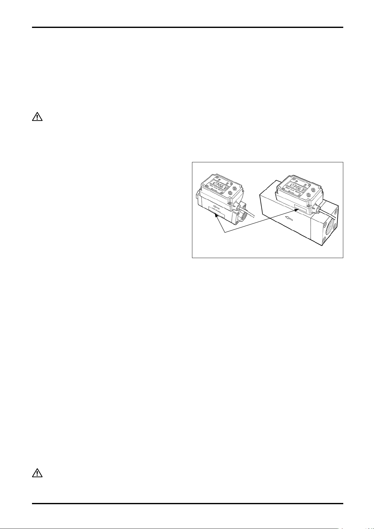
1.1 Confirming the Nameplate
Ev e r y O VAL m o n i tor is carefull y a s s e m b l e d a n d
accurately adjusted to first-class condition. Product
code number and ratings appear on the nameplate. By
referring to the general specifications in Section 9 and
product code explanation in Section 11, make sure
that the product you received is fully in compliance
with your order.
When you make inquiries, include the product name, model number, stock
number, ratings and other pertinent information.
Nameplate
(ratings shown)
1.2 Transportation Considerations
(1) It is desirable that the monitor be transported to the installation site in the shipping container used for
transit from the factory.
(2) During transportation, exercise care to avoid impact shock and rainwater.
1.3 Storage Considerations
Storing your mass flow monitor for long periods of time upon receipt before installation can result in
un exp ecte d and undes irab le conditions . Whe n long -term storage is anti cipa ted, take th e following
precautions:
(1) The monitor can best be stored in the shipping container used for transit from the factory.
(2) Select the storage place that meets the following requirements:
★ free from rain and water
★ free from vibration and impact shocks
★ with least temperature and humidity variation (around 25°C and 65% R.H).
(3) A monitor that has once been placed in service for any length of time should be washed clean to remove
residue of metered material completely from its main body, joint, conduit, and outer case before storage.
Especially, purge the inner wall of flow path with clean air or nitrogen gas, and then protect the flow inlet
and flow outlet against entry of dust inside.
CAUTION:
1. At cleansing, do not use solvents, such as thinner and alcohol.
2. Never attempt to cleanse the interior flow path with detergent.
3
S-193-11-E
2. OPERATING CONDITIONS
The monitor operating conditions are stated on the specification label, Section 5 "INSTALLATION" and Section
9 "GENERAL SPECIFICATIONS." Read carefully before initiating operation.
CAUTION:
This monitor is of non-explosionproof configuration; it is not serviceable in a
hazardous location.
3. GENERAL
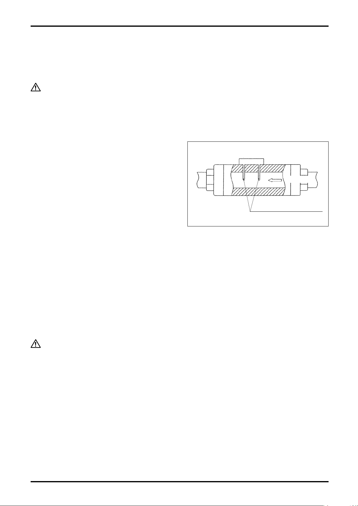
This monitor is a small, lightweight flowmeter, using a
heat-sensitive resistance element.
Of the two heat-sensitive resistance elements located
perpendicular to the fluid flow; one detects the fluid
temperature and the other, which plays the rol e of
a heater, regulates the temperature of the former to
maintain a constant temperature differential. As the
flow ing process f l uid (ma s s f low) d i s sipate s h e at
from the latter which ser ves as a heater, its supply
power increases in order to maintain the temperature
differential. This change in power consumption (voltage
and current) is used to calculate the mass flowrate.
Heat-sensitive
resistance elements
Fig. 3.1
Flow direction
3.1 Features
(1) Absence of moving parts contributes to long life.
(2) Major components are made of synthetic resin. Lightweight and compact.
(3) Sturdy metallic couplings.
(4) The display is a backlit LCD for readability in darkness.
(5) May be installed in any position. The display can be oriented in 90 deg steps to see easily.
CAUTION:
Adjusting the display orientation requires opening the upper case of transmitter.
The procedure to change orientation appears in Section 5.3 "How to Change
Display Orientation".
4

4. COMPONENT NAMES AND FUNCTIONS
4.1 Part Names
S-193-11-E
LCD display
(Unit indicator)
③ Transmitter
② Sensor
Alarm 1 LED
Alarm 2 LED
⑤ RESET button
④ MODE button
Screw
connection
Flow direction
① Monitor body
Mounting hardware (option)
Fig. 4.1
4.2 Individual Functions
No. Part Name Description
① Body Consists of a measuring tube, straightener, and rectification mesh.
Consists of two heat-sensitive resistance elements. Power supply (voltage and current)
② Sensor
③ Transmitter
④ Mode button Changes display modes to the instant flowrate or total flow. (See Sec. 8.1 for details.)
⑤ Reset button Used to reset the "Resettable total flow" to zero.
CAUTION:
to one of the heat-resistive resistance elements changes to maintain the heat resistance at a constant level (approx. 30°C).
Changes in supply power (voltage and current) are transformed into a flowrate signal
which can be monitored on a 8-digit LCD display in terms of instant flowrate and total
flow.
Do not attempt to disassemble the meter. If the flow path is badly contaminated
or a malfunction is suspected, contact the nearest customer service network in
your area. Unauthorized disassembly will void the warranty.
5

S-193-11-E
5. INSTALLATION
5.1 Installation Location
This monitor is for indoor use.
Select an installation location that meets the requirements set forth below.
CAUTION:
(1) Free from rain and water.
(2) Least temperature variation.
(3) Free from direct exposure to the sun.
(4) Least vibration and impact shock.
(5) Easy to read the display and accessible for servicing.
(6) Process condition to keep fluid pressure not to exceed the permissible pressure of 0.7 MPa.
5.2 Physical Orientation
This monitor is NOT serviceable in a hazardous location.
There is no restriction on physical orientation of the monitor to cause loss of the accuracy.
Make sure that the actual flow direction conforms to the flow direction arrow indicated on the monitor body.
NOTE: The display orientation can be adjusted in 90 deg steps to see easily (see Section 5.3).
5.3 How to Change Display Orientation
This work is done with the transmitter subassembly removed. Observe the following instructions:
(1) Work in a clean environment before installing the monitor in the tubing system.
(2) Avoid working in a moist or dusty environment.
(3) Exercise care to avoid damaging the components on the electronics substrate while you work.
Required tools: Screwdrivers (for M3 and M2.6 cross recess pan head screws).
Display orientation is adjustable in 90 deg steps as shown below:
90° to the left
Standard
(at shipment from factory)
90° to the right
180°
Flow Direction
Fig. 5.1
6
S-193-11-E
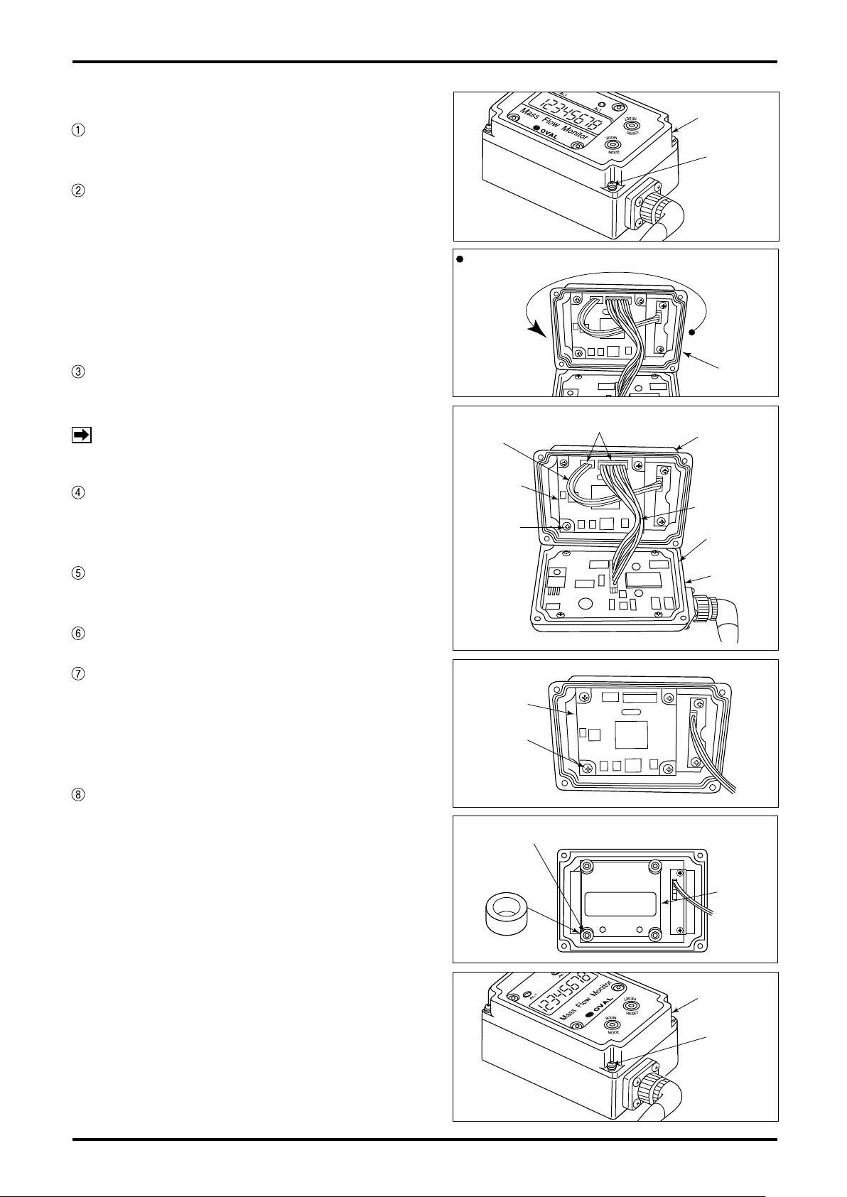
How to Change Display Orientation
If power is supplied, shut it off. (Make sure
nothing appears on the LCD).
Take off four set screws (3×14) securing the
upper case to the transmitter and carefully
open the upper case (Fig. 5.2).
If a 180 deg. turn is your option, turn the upper
case the other way with lead wires intact (Fig.
5.3).
To turn 90 deg. clockwise or counterclockwise
follow the steps given below.
Take off four set screws (2.6×8) holding the
display board in place and remove the display
board (Fig. 5.5).
NOTE:
Remove four spacers (white rings) attached to
the bosses that have secured the display board
in place (Fig. 5.6).
Do not take out the screws fixing amp
board on lower case in any case.
Upper Case
Setscrew
(4 PLC'S)
Fig. 5.2
Turn the upper case 180°, with cables intact.
Upper
Fig. 5.3
Cable Connectors
3-wire
Cable
Display
Board
Setscrew
(4 PLC'S)
Case
Upper Case
10-wire Cable
O-Ring
Extract the top panel and put it onto the upper
case then in the different orientation.
Install the removed spacers over the bosses.
Place the display board in line with the top
panel and secure it with four screws (2.6×8
with tightening torque 45cN・m). (Align the
opening in the top panel with the mating LED
on the display board).
Make certain that O-ring fits in the groove
of lower case and, exercising care against
pinched cables, secure the upper case with
four screws (3×14 with tightening torque of
60cN・m). Tighten them in an alternating order
to ensure even tightening (Figs. 5.7).
Fig. 5.4
Display
Board
Setscrew
(4 PLC'S)
Fig. 5.5
Bosses (4 PLC'S)
Spacer
(4 PLC'S)
Fig. 5.6
Lower
Case
Top Panel
Fig. 5.7
Upper Case
Setscrew
(4 PLC'S)
7
S-193-11-E
5.4 Conditions Required for Metered Fluid
Due to the fact that this monitor is a thermal flowmeter, contamination buildup can cause loss of accuracy. In
an environment where entrapment of contaminants, such as dust, oil, and water, is anticipated, it is a good
practice to provide a filter, drain, separator or similar arrangement upstream of the monitor.
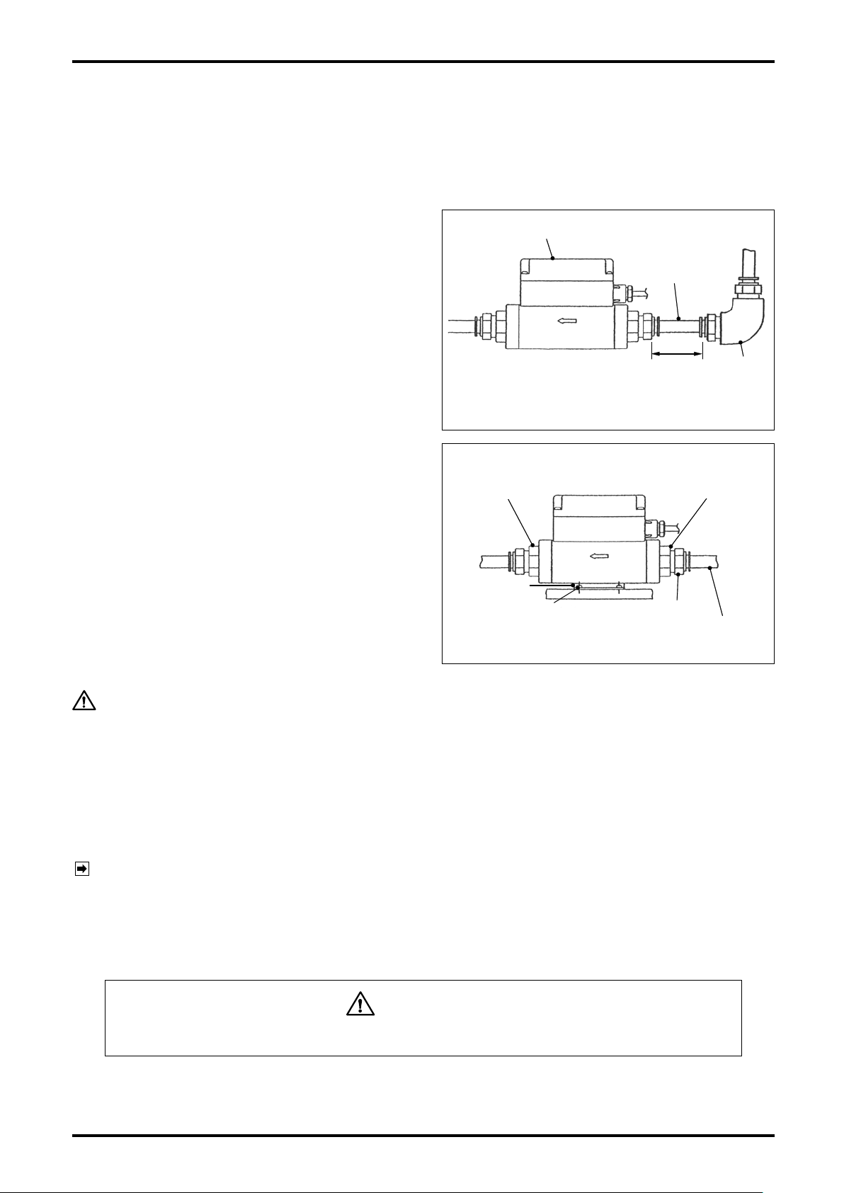
5.5 Tubing Guidelines
(1) Required Tubing Conditions
Since the monitor has a built-in straightener,
tubing conditions, such as differences in tube
diameter, for example, rarely present a problem.
However, if an elbow is to be located upstream
of the monitor, provide a straight tube about the
length of a nipple (3D min.). Direct installation of
an elbow may possibly cause an error of ±1 %
F.S. or so.
There is no restriction on tubing arrangements
downstream of the monitor.
(2) Installation of mounting hardware (option for
meter sizes 15mm and 20mm).
Required tool: Torque screwdriver that fits M3
cross recess pan head screws.
Do not use any other accessories except for the
furnished dedicated screws (tap-tight screws
3 x 8). See outline dimensions in Sec. 12 for
Installation location and orientation.
Torque specification: 60±3 cN・m
Meter Fitting
Meter fitting
Monitor body
Screw
Straight tube
30 min.
D: Meter I.D.
Fig. 5.8
Mtg. Hardware
Quick-connect coupling
Synthetic resin tube
Fig. 5.9
Elbow
CAUTION:
With metal tubes, tubing stresses could damage the flowmeter at its metal
fittings. Do not use the mounting hardware with metal tubes. Instead, secure
the metal tubes with U-bolts or similar fittings.
(3) Tube Connection Procedure (for meter sizes 15mm and 20mm)
1. Connecting parts are of aluminum die casting: avoid forcibly installing them and giving an impact
shock. The monitor body is of synthetic resin: avoid applying stresses on it. Torque specification: 30 ±
1 (N・m)
NOTE: Hold the hexagonal flats of aluminum die cast connection firmly with wrench, or similar tool, when
you work (Fig. 5.9).
2. Use care to safeguard the transmitter from coming in contact with tools, such as wrench.
3. Do not hold the transmitter by force while connecting it to the tubing system.
4. Providing a union before and after the flowmeter is suggested to facilitate flowmeter removal.
WARNING
Negligence of the precautions above may result in damaged components.
(4) Flushing
If foreign solids are expected to get into the tubing system, particularly on a new installation, flushing of
the tubing assembly thoroughly is essential before installing the monitor.
8
S-193-11-E
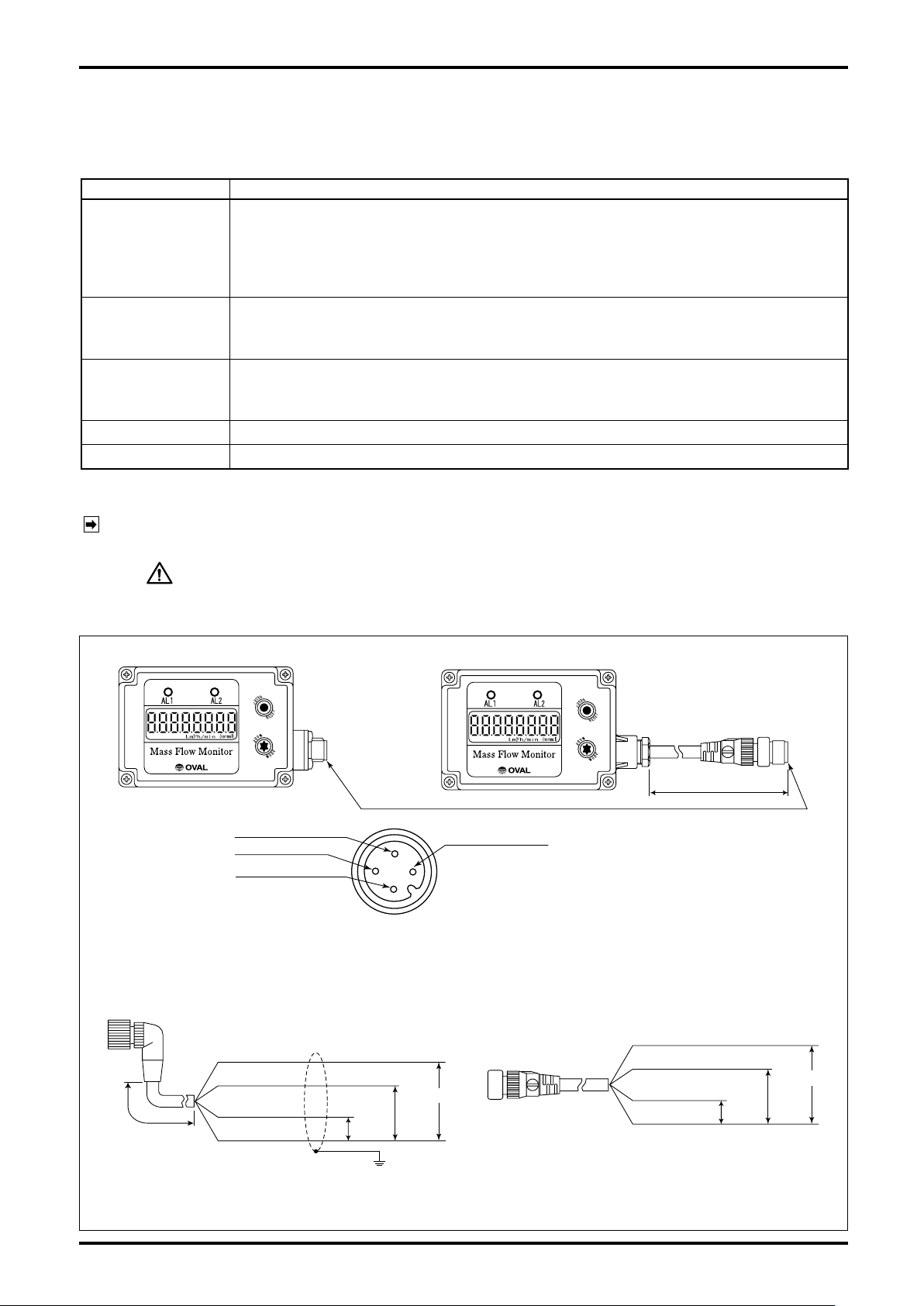
9000
8000
7000
6000
5000
4000
3000
2400
2200
2000
1000
0
0 0.1 0.2 0.3 0.4 0.5 0.6 0.7
0.240.11
Line pressure [MPa]
Max. service flowrate [L/min (normal)]
Nominal size 40 mm
Nominal size 50 mm
Nominal size 25 mm
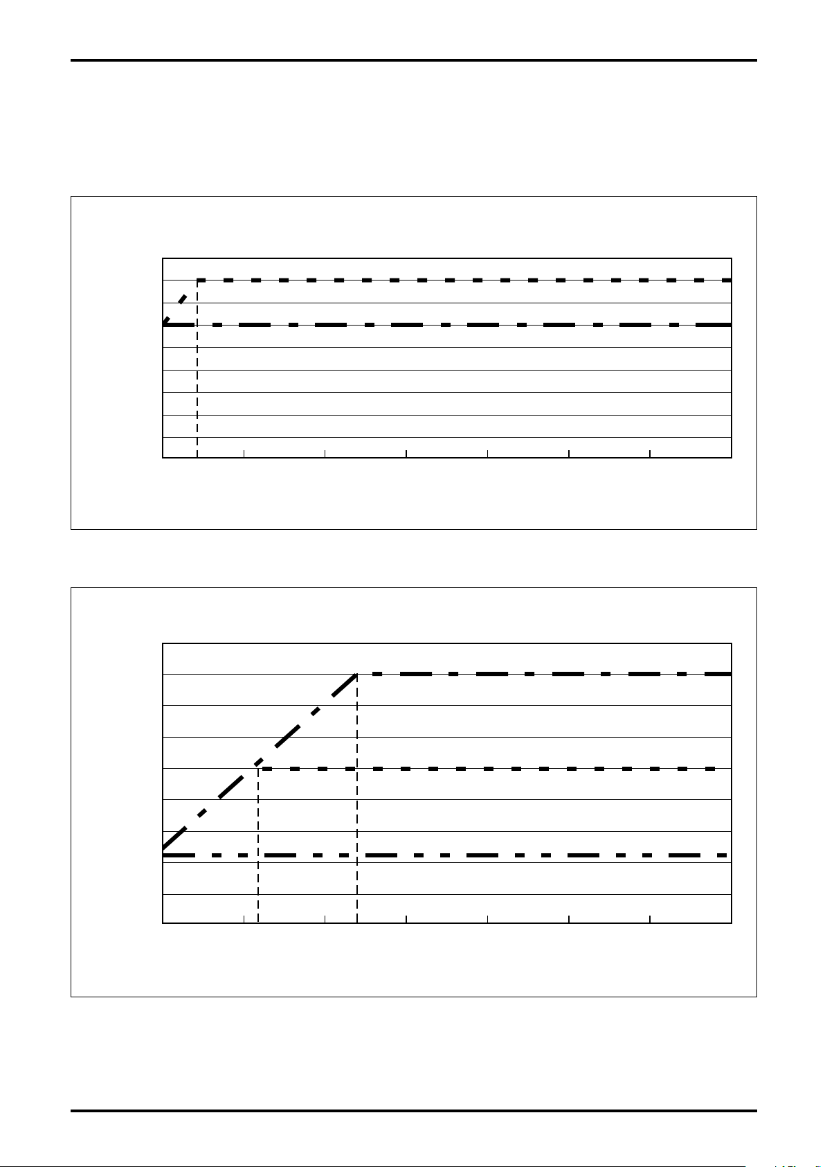
900
800
700
600
500
400
300
200
100
0
0 0.1 0.2 0.3 0.4 0.5 06 0.7
0.04
Line pressure [MPa]
Max. service flowrate [L/min (normal)]
Nominal size 20 mm
Nominal size 15 mm
5.6 Maximum Service Flowrate
The maximum service flowrate varies with line pressure. Measurement continuation at larger service flowrates
may possibly damage the sensor. Therefore, determine the maximum service flowrate from the following
graphs and place the sensor in service within the rate so obtained.
■ Line pressure vs. maximum service flowrate (nominal sizes 15mm and 20mm)
■ Line pressure vs. maximum service flowrate (nominal sizes 25mm, 40 and 50mm)
9
S-193-11-E
1: SUP (power +)
4: Flow pulse output
3: COM (power-)
GND
Shieldedwire
ConnecttheshieldedwiretoGND.
BRN:SUP(power+)
WHT:Alarm1output
YEL:Flowpulseoutput
GRN:COM(power-)
max.
30VDC,
20mADC
max.
30VDC,
20mADC
24VDC±10%
BRN:SUP(power+)
2: Alarm 1 output
Connector terminal
1
3
4
2
WHT:Alarm1output
BLK:Flowpulseoutput
BLU:COM(power-)
max.
30VDC,
20mADC
max.
30VDC,
20mADC
24VDC±10%
●Cable (OMRON)
●Cable (OVAL)
Model: XS2F-D42□-□80-F
Note: For cables, refer to the following figures.
• When product code "Output terminal" is [2] or [4], OVAL cable is supplied.
• When product code "Output terminal" is [3] or [5], cable must be prepared by the customer.
In this case, OMRON cable is recommended.
25 cm
3m
6. WIRING CONNECTIONS
6.1 Wiring Specifications
Table 6.1
Item Description
The following cables are supplied depending on the 15th digit of the product code.
Transmission cable
(Depends on your
specification).
[1]: 5-conductor shielded cable of 3 meters long (O.D.: 6.3mm) ... Fixed to this
unit.
[2][4]: 4-conductor shielded cable of 3 meters long (O.D.: 6.3mm, 4-pin connector is
provided at the one side of the cable) ... Supplied with this unit.
Open collector output
Alarm output
Allowable current: 20mADC
Max. voltage impression: 30VDC
Open collector output
Flow pulse output
Allowable current: 20mADC
Max. voltage impression: 30VDC
Flow analog output 4 to 20mA corresponding to 0 to F.S.
Supply Voltage 24VDC±10%
6.2 Wiring Diagram
NOTE: For output terminal types and styles, see "Explanation of Output Terminal Types" below NOTES in
Sec. 11.
CAUTION:
1. Use extra care about the polarities of power source.
2. Do not fail to earth ground the shielded wire to GND.
(1) Flow pulse output + single alarm point specifications (Fig. 6.1)
● Connector terminal
● Connector via interconnect cable
10
Fig. 6.1

1: SUP (power +)
4: Alarm 1 output
3: COM (power -)
GND
Shieldedwire
ConnecttheshieldedwiretoGND.
BRN:SUP(power+)
WHT:Flowanalogoutput
YEL:Alarm1output
GRN:COM(power-)
max.
30VDC,
20mADC
4to20mA
max.
500Ω
4to20mA
max.
500Ω
24VDC±10%
BRN:SUP(power+)
2: Flow analog output
Connector terminal
1
3
4
2
WHT:Flowanalogoutput
BLK:Alarm1output
BLU:COM(power-)
max.
30VDC,
20mADC
24VDC±10%
●Cable (OMRON)
●Cable (OVAL)
Model: XS2F-D42□-□80-F
Note: For cables, refer to the following figures.
• When product code "Output terminal" is [2] or [4], OVAL cable is supplied.
• When product code "Output terminal" is [3] or [5], cable must be prepared by the customer.
In this case, OMRON cable is recommended.
25 cm
3m
(2) Flow analog output + one alarm specifications (Fig. 6.2)
S-193-11-E
● Connector terminal
● Connector via interconnect cable
Fig. 6.2
11

S-193-11-E
GND
Shieldedwire
ConnecttheshieldedwiretoGND.
BRN:SUP(power+)
WHT:Flowanalogoutput
YEL:Flowpulseoutput
GRN:COM(power-)
max.
30VDC,
20mADC
4to20mA
max.
500Ω
4to20mA
max.
500Ω
24VDC±10%
BRN:SUP(power+)
Connector terminal
1
3
4
2
WHT:Flowanalogoutput
BLK:Flowpulseoutput
BLU:COM(power-)
max.
30VDC,
20mADC
24VDC±10%
Model: XS2F-D42□-□80-F
25 cm
3m
1: SUP (power +)
4: Alarm 1 output
3: COM (power -)
2: Flow analog output
●Cable (OMRON)
●Cable (OVAL)
Note: For cables, refer to the following figures.
• When product code "Output terminal" is [2] or [4], OVAL cable is supplied.
• When product code "Output terminal" is [3] or [5], cable must be prepared by the customer.
In this case, OMRON cable is recommended.
(3) Flow pulse output + flow analog output specifications (Fig. 6.3)
● Connector terminal
● Connector via interconnect cable
Fig. 6.3
12

GND
Shieldedwire
ConnecttheshieldedwiretoGND.
BRN:SUP(power+)
WHT:Alarm1output
YEL:Alarm2output
GRN:COM(power-)
max.
30VDC,
20mADC
max.
30VDC,
20mADC
24VDC±10%
BRN:SUP(power+)
Connector terminal
1
3
4
2
WHT:Alarm1output
BLK:Alarm2output
BLU:COM(power-)
max.
30VDC,
20mADC
max.
30VDC,
20mADC
24VDC±10%
Model: XS2F-D42□-□80-F
25 cm
3m
1: SUP (power +)
4: Alarm 1 output
3: COM (power -)
2: Flow analog output
●Cable (OMRON)
●Cable (OVAL)
Note: For cables, refer to the following figures.
• When product code "Output terminal" is [2] or [4], OVAL cable is supplied.
• When product code "Output terminal" is [3] or [5], cable must be prepared by the customer.
In this case, OMRON cable is recommended.
(4) Two alarm point specifications (Fig. 6.4)
S-193-11-E
● Connector terminal
● Connector via interconnect cable
Fig. 6.4
13

S-193-11-E
3m
GRY:Alarm1output
YEL:Flowpulseoutput
WHT:Alarm2output
BRN:SUP(power+)
GRN:COM(power-)
max.
30VDC,
20mADC
max.
30VDC,
20mADC
max.
30VDC,
20mADC
24VDC±10%
GND
Shieldedwire
ConnecttheshieldedwiretoGND.
GRY:Alarm1output
YEL:Flowpulseoutput
WHT:Flowanalogoutput
BRN:SUP(power+)
GRN:COM(power-)
max.
30VDC,
20mADC
max.
30VDC,
20mADC
4to20mA
max.
500Ω
24VDC±10%
GND
Shieldedwire
ConnecttheshieldedwiretoGND.
3m
(5) Flow pulse output + two alarm points specifications (Fig. 6.5)
● Direct coupled cable
Fig. 6.5
(6) Flow pulse output + flow analog output + single alarm point specifications (Fig. 6.6)
● Direct coupled cable
Fig. 6.6
CAUTION:
If "Without cable" is specified for the product, the cable shown in the wiring diagram
is not supplied with the product.
6.3 Cable Specifications
Applicable cable depends on the specifications of the 15th digit "Output Terminal" of the product code. Refer
to the following table.
15th digit of
product code
「1」 Cable coupled directly
「2」
「4」
「3」
「5」
※1 For the kind and shape of the output terminal, refer to the section "Explanation of Output Terminal".
"Output Terminal"
specifications ※1
Connector via
interconnect cable
(with cable)
Connector terminal
(with cable)
Connector via
interconnect cable
(without cable)
Connector terminal
(without cable)
Cable Specifications State at shipment from factory
[OVAL cable]
5-conductor shield cable
Length: 3 m, O.D.: 6.3 mm
[OVAL cable]
4-conductor shield cablewith connector
Length: 3 m, O.D: 6 mm
[Recommended cable]
Manufacturer: OMRON
Model: XS2F-D42□-□80-F
Name: Cabled connector socket single side connector
Length: As specified by the customer
O.D.: 6 mm
Directly coupled to the product body.
Packed together with product body.
Cable is not supplied with the product.
To be prepared by the customer. The cable shown on the left is recommended.
(Purchase the cabl e directl y from the
manufacturer.)
7. OPERATION
(1) Verify that the process fluid conditions (such as pressure and temperature) meet the ratings specified.
(2) After confirming the wiring connections, turn on power and see that the flowrate reads zero.
(3) Making sure there is no leaks at tube connections, carefully open the upstream valve.
1. Just after powering on, this equipment is ready for measurement. However, the optimum
CAUTION:
accuracy is available 30 minutes after power on.
2. To safeguard the monitor against damage, avoid sharp increase in flowrate.
14

S-193-11-E
8. TRANSMITTER DISPLAY FUNCTIONS AND RECONFIGURATION
8.1 Viewing the Flow Variables
The flow monitor can show seven flow variables, one at a time.
With each depression of the "MODE" button, the display scrolls through available variables as shown in the
diagram below. Keep on pressing the "MODE" button until the variable desired appears.
(Immediately after powerup, the display shows the most recently selected variable before power was turned
off. "X" in each box at left represents a numerical value of the variable).
Menu item Description
MODE
X
MODE
MODE
X
....................
.
....................
.
....................
.
....................
Accumulated
total flow
Instant
flowrate
(hourly)
Instant
flowrate
(per-minutes)
Resettable
total flow
Indicates the total flow accumulated until now.
(The accumulated total is not resettable to "0".)
Reads in m3 (normal).
Indicates the per-minute instant flowrate.
Reads in m3/h (normal).
Indicates the hourly instant flowrate.
Reads in L/min (normal).
Indicates the total flow that has flown since the last RESET operation. (Pressing the "RESET" button while total reset flow is
displayed sets the total flow to "0".)
Reads in m3 (normal).
X.X.X.X.X.X.X.X
Accumulated total
Press
X.X.X.X.X.
Instant. flowrate (hourly)
Press
X.X.X.X.X.X
Instant. flowrate
(per-min)
Press
X.X.X.X.X.X.
Resettable total
MODE
Press
X.X.X.X.X.X.
Yen converted accum.
total
X.X.X.X.X.
Yen converted instant.
Flowrate (hourly)
X.X.X.X.X.
Yen converted
resettable total
Press
Press
Press
X
MODE
X
MODE
X
MODE
.
....................
Accumulated
total flow in
terms of Yen
Accumulated total flow in terms of Yen which is the product of
flowrate and Yen conversion factor.
Reads in Yen. (Unit of registration is not shown.)
※1
.
....................
.
....................
.
Instant
flowrate in
terms of Yen
(hourly) ※1
Resettable
total flow in
terms of Yen
※1
Instant flowrate in terms of Yen which is the product of flowrate
and Yen conversion factor.
Reads in Yen/h.
(Only /h appears for the unit of registration.)
Resettable total flow in terms of Yen which is the product of
flowrate and Yen conversion factor.
Reads in Yen. (Unit of registration is not shown.)
Indicates the total flow that has flown since the last RESET operation. (Pressing the "RESET" button while the resettable total
flow in terms of Yen appears resets this reading to "0".)
NOTE ※1: By establishing the Yen value per unit fluid volume of 1m3 (normal) to the
Yen conversion factor, the monitor can show accumulated total, instant
flowrate, and resettable total, each in terms of Yen.
(When "0" is set to the Yen conversion factor, the accumulated total, instant
flowrate, and resettable total, each in terms of Yen, will not appear. Factoryset default Yen conversion factor is "0".)
15

S-193-11-E
8.2 Parameter Display
Alarm-related parameters are shown on the left half; remaining parameters and special functions are on the
right half of the diagram. To change parameters, scroll through menu items until the parameter you want to
change is shown before you make necessary changes.
To restore flow variables, hold the "MODE" button depressed for 5 seconds either at,
Flow variables (accum. total, instant flowrate, resettable total and accum, total, instant. flowrate, resettable total, each in terms of Yen)
MODE
Press
Press
for 5 sec.
RESET
.
ALA
, or
bdAtA
window.
Alarm menu
MODE
Press
X.X.X.X.
Alarm 1 setpoing
Press
X.X.X.X.
Alarm 1 hysteresis
Press
Alarm 1 status
Press
X.X.X.X.
Alarm 2 setpoing
Press
X.X.X.X.
Alarm 2 hysteresis
Press
Alarm 2 status
Press
X.X.X.X.
Low alarm dead zone
Press
Alarm dead duration
Press
MODE
MODE
X.X
MODE
MODE
MODE
X.X
MODE
MODE
X.X
MODE
.
X
.
X
.
.
X
.
X
.
.
X
.
.
....................
....................
....................
....................
....................
....................
....................
....................
Menu item Description
Alarm 1
setpoint
Alarm 1 setpoint.
Beyond this setpoint, an alarmed condition takes place. (During
the time of alarm dead zone, alarm output and LED indication
remain inactive, however).
Set the flowrate to activate an alarm.
Setpoint reads in L/min (normal).
Alarm 1
hysteresis
Alarm 1 hysteresis.
If flowrate fluctuation is excessive, causing frequent alarm ONOFF trips, select a larger value.
Setpoint reads in L/min (normal).
Alarm 1
status
Alarm I status setpoint.
By selecting either code of the following to the upper digit, you
can set up the type of errors to be identified.
H: High alarm L: Low alarm
By setting either code of the following, you can set up the status of open collector output in an error.
o: OFF in an error S: ON in an error
Alarm 2
setpoint
Alarm 2
hysteresis
Alarm 2
status
Low alarm
dead zone
Alarm 2 setpoint.
The functions remain the same as Alarm 1 setpoint.
Alarm 2 hysteresis.
The functions remain the same as Alarm I hysteresis.
Alarm 2 detailed status setting.
The functions remain the same as alarm 1 status.
The lower limit to activate an alarm. Below this flowrate, alarm
remains inoperative even if alarm conditions are met.
Reads in L/min (normal).
Alarm dead
duration
Delay time of identifying an alarm. Any alarm condition does
not activate an alarm at once; only after the expiration of this
duration.
Read in seconds.
Press
RESET
.
16

S-193-11-E
To view parameters of interest, hold the "MODE" button depressed for 5 seconds at the flow variables
window to show
"RESET" buttons until the parameter desired appears.
("XXX" in each box at left represents a numerical value of the variable).
Basic data menu
Press
X.X.X.X.X.X.
Press
X.X.X.X.X.
Press
X.X.
Press
X.X.
Press
Press
X.X.X.X.X.X
Press
Press
X.X.X.X.X
Press
X.X.X.X.X
Press
Press
Press
Press
ALA
window. The diagram below will lead you the rest of the way using the "MODE" and
MODE
Press
MODE
.
....................
X
Yen conversion
factor
MODE
.
....................
X
Pulse weight
MODE
.
....................
X
Pulse ON width
MODE
.
....................
X
Cutoff
MODE
.
....................
Dummy output
MODE
.
....................
Full scale flowrate
MODE
.
X.X.X.X
Damping time
MODE
....................
.
....................
Analog trim (4mA)
MODE
.
....................
Analog trim (20mA)
MODE
.
....................
Zeroing
MODE
.
X.X
Backlight setting
MODE
....................
.
....................
All figure places
illuminated
MODE
.
NOTES: 1. See Sec. 8.3 for acceptable parameter setting
for 5 sec.
2. ※1: Models not provided with an analog
range and factory set defaults.
output do not show these menu items.
Menu item Description
Yen
conversion
factor
Pulse weight Unit flowrate per single output pulse.
Pulse ON
width
Cutoff Instantaneous flowrate cutoff setpoint.
Dummy
output
Analog Full
scale flowrate
Analog
Damping time
Analog trim
(4mA)
Analog trim
(20mA)
Zeroing Adjusts the zero baseline. The product is shipped after calibration in
Backlight
setting
All figure
places
illuminated
A parameter to perform conversion to obtain Yen equivalent. Yen
equivalent represents the cost per unit flow of 1 m3 (normal) of metered process fluid.
Reads in Yen/m3 (normal).
When set to "0", Yen conversion does not take place.
Reads in L (normal).
To change the setpoint, be sure to meet the following conditions. Unless these conditions are satisfied, proper pulse output is not produced.
Max. service flowrate [L/min (normal)] / pulse weight
[L(normal)] x (pulse "ON" [msec] + 1) / 60 < 1000
Output pulse width.
Reads in msec.
Unless the same conditions as those of pulse weight are satisfied,
proper pulse output is not produced.
Any flow below this flowrate reads "0".
Reads in L/min (normal).
A 10Hz pulse output is available irrespective of the flowrate curently
in measurement. You can use this feature in verifying the connections
with other system, or for other purpose. (For the procedure of producing dummy output, see Sec. 8.6 "Dummy Pulse Output".)
Flowrate at analog output full scale (20mA).
※1
Sets damping time for analog output. (Due to inherent circuit properties, approx. 1 sec time const. exists besides software setting.)
※1
Reads in sec.
Trims analog output of 4mA.
(For details, see Sec. 8.7 "Analog Output Trim".)
※1
Trims analog output of 20mA.
(For details, see Sec. 8.7 "Analog Output Trim".)
※1
the factory. Normally, the product does not require Zero baseline adjustment.
To adjust, press ahd hold the "MODE" button for more than 5 seconds while pressing the "RESET" button in this mode.
You can select any one of four backlight activation modes.
On: Illuminated full time, EC: Illuminated full time at the half level of
illumination at On time, OF: Always unlit, SL: Illumination darkened to
half approx. 10 sec. after completing button operation.
This feature is useful in testing the illumination of LCD display and
alarm LED indicator lamps.
Illuminates all LCDs and alarm LEDs.
(Alarm output appears as usual.)
17

S-193-11-E
8.3 Default Parameter Settings
Parameters are set to the following default settings before shipment from the factory:
Top row: Parameter name
Middle row: Unit of numerical value
Bottom row: Settable range
Alarm 1 setting
L/min (normaI)
0 to 99999
Alarm 1 hysteresis
L/min (normal)
0 to 99999
Alarm 1 status
Ho, HS, Lo, LS
Alarm 2 setting
L/min (normal)
0 to 99999
Alarm 2 hysteresis
L/min (normal)
0 to 99999
Alarm 2 status
Ho, HS, Lo, LS
Low limit in alarm immunity range
L/min (normal)
0 to 99999
Alarm immune time
Seconds
0 to 99
Yen conversion factor
Yen 1m3 (normal)
0 to 999.999
Pulse weight
L (normal)
0.01 to 9999.99
Pulse width
msec
1 to 240
Cutoff ※1
L/min (normal)
0 to 99999
Analog full scale
L/min (normal)
0 to 99999
Analog Damping
sec
0 to 99
Backlight setting
On, EC, OF, SL
15mm 20mm 25mm 40mm 50mm
50 65 200 400 650
10 15 35 85 135
LS LS LS LS LS
600 800 2200 5000 8000
10 15 35 85 135
HS HS HS HS HS
10 15 35 85 135
3 3 3 3 3
2.000 2.000 2.000 2.000 2.000
0.1 0.1 1.00 1.00 1.00
5 5 5 5 3
9 14 34 84 134
600 800 2200 5000 8000
0 0 0 0 0
On On On On On
Factory default settings
Nominal size
NOTES: ※1: Cutoff set value must not be changed in other than the following cases.
(1) When output is given though the flow is stopped (※).
Set the cutoff value a little greater than the output value at that time.
(2) When you want to measure the flowrate of the area lower than the cutoff value, set the
cutoff value lower than the desired flowrate.
Under some condition, the difference at this area may be greater depending on the offset
value of the zero point. Therefore, adjust zero point while the flow is stopped (※) as
necessary.
※ The stoppage of flow refers to the status where the valve at the lower stream of this unit is
fully opened under the process condition in use and there is no leakage from the valve.
18

8.4 Parameter Reconfiguration
An example below shows the procedure to change Alarm 2 setting from 600 to 500.
For display operating procedure, see Section 8.2 "Parameter Display".
Description
600
Press
MODE
....................
for 2 sec.
[Show the alarm 2 setting.]
Hold the "MODE" button depressed for more than 2 seconds. When the screen
begins to blink, remove your finger from the button.
(Write mode becomes active and the figure in the ones place blinks.)
S-193-11-E
600
Press
600
Press
500
Press
500
MODE
RESET
MODE
....................
for 2 sec.
....................
9 times.
....................
for 2 sec.
....................
[The figure "0" in the right-most place blinks.]
Press the "MODE" switch twice to allow the digit in the hundreds place to blink.
(Pressing the "MODE" button moves the blinking digit one place to the left).
["6" in the hundreds place blinks.]
Press the "RESET" button 9 times to adjust the figure to 5.
(Pressing the "RESET" button increases the blinking figure.)
[The digit in the hundreds place changes to "5" while blinking].
Now the reading has been changed to 500.
To save this value, hold the "MODE" button depressed for more than 2 seconds.
When the screen begins to blink, remove your finger from the button. (The
setting is saved and you exit the write mode.)
If you want to exit the write mode without completing the setting, hold the
"RESET" button depressed for more than 2 seconds. When the screen begins
to blink, remove your finger from the button. (You exit the write mode without
saving any value.)
[The indicator stops blinking and stays on.]
Now the setup process is complete.
19

S-193-11-E
8.5 Alarm Features
In this monitor, settings of alarms 1 and 2 are adjustable to any levels to help you keep on monitoring the
process flow. And by setting up two parameters - "lower limit in alarm immunity range" and "alarm immunity
time," precise alarm settings can be established against leaks. Follow the instructions given in this manual
when you set up alarm set points. Examples of alarm setup are also given in this section.
CAUTION:
(1) Setting up the high alarm
Parameters related to the high alarm come in the following five, (1) through (5). Set each of them by
referring to the description given for individual parameters.
① Alarm setpoint
Set the flowrate [(L/min (normal)) to be at the upper alarm.
② Alarm hysteresis
If alarm features are not desired, set the alarm set points to "0" (alarm status
either at high alarm or lower alarm).
Alarm is cancelled when the following conditions are met. Select the appropriate alarm hysteresis [L/
min (normal)].
Flowrate < Alarm setpoint - Alarm hysteresis
If variation in flowrate is excessive, resulting in frequent alarm ON-OFF cycling, set a little larger value.
③ Alarm status (higher digit)
Setting is to be made on the high alarm: set "H" to the higher digit.
④ Alarm status (lower digit)
Set up the output status to the lower digit in an alarmed condition.
Selecting "S" results in an "ON" output (Lo impedance) in an alarmed condition.
Setting "o" results in an "OFF" (Hi impedance) in an alarmed condition.
⑤ Alarm immunity time
Set the delay time [in sec] from the moment the flowrate exceeds the alarm set value to the moment
an alarm is activated. Remember that setting of this parameter is common to both alarms 1 and 2.
20

S-193-11-E
Stays off
Alarm 2 setpoint
Flowrate →
[L/min(normal)]
Alarm 2 hysteresis
Instant flowrate
OFF
Comes on
ON
Stays off
OFF
Comes on
ON
Alarm 2 LED
Alarm 2 output
Time
→
Withinalarmimmunitytime
→
Beyondalarmimmunitytime
→
Stays off
Alarm 2 setpoint
Flowrate →
[L/min(normal)]
Instant flowrate
OFF
Comes on
ON
Stays off
OFF
Comes on
ON
Alarm 2 LED
Alarm 2 output
Time
→
Alarm 2 hysteresis
■ Example of high alarm setup
Given below is an example of setting up the alarm 2 for high alarm.
● Setup example 1 (where "alarm hysteresis" and "alarm immunity time" are involved.)
・Alarm conditions: When the following condition continues beyond the alarm immunity time.
Instant flowrate ≧ Alarm setpoint
・Alarm cancel conditions: Instant flowrate < Alarm setpoint - Alarm hysteresis
Parameter Name Setting
Alarm 2 setpoint
[L/min (normal)]
Alarm 2 hysteresis
[L/min (normal)]
Alarm 2 status
(higher digit)
Alarm 2 status
(lower digit)
Alarm immunity
time
[sec]
NOTES: If alarm 2 status (lower digit) is set to "o", the "ON" and "OFF" of alarm 2 output become the
opposite states shown in the above figure.
● Setup example 2 (where "alarm hysteresis" exists and "alarm immunity time" is set to "0".)
・Alarm conditions : Instant flowrate ≧ Alarm setpoint
・Alarm cancel conditions : Instant flowrate < Alarm setpoint - Alarm hysteresis
550
20
H
S
3
Parameter Name Setting
Alarm 2 setpoint
[L/min (normal)]
Alarm 2 hysteresis
[L/min (normal)]
Alarm 2 status
(higher digit)
Alarm 2 status
(lower digit)
550
20
H
S
Alarm immunity
time
0
[sec]
NOTES: When alarm 2 status (lower digit) is set to "o", the "ON" and "OFF" of alarm 2 output become
the opposite states shown in the above figure.
21

S-193-11-E
(2) Setting up the low alarm
Parameters related to the low alarm come in the following six. Set each of them by referring to the
description given for individual parameters.
CAUTION:
① Alarm setpoint
Set the flowrate [(L/min (normal)) to be at the low alarm.
② Alarm hysteresis
Alarm is cancelled when the following condition is met. Select the appropriate alarm hysteresis [L/min
(normal)].
Flowrate > Alarm setpoint + Alarm hysteresis
If variation in flowrate is excessive, resulting in frequent alarm ON - OFF cycling, set a little larger
value.
③ Alarm status (higher digit)
Setting is to be made on the low alarm: set "L" to the higher digit.
Remember that at "0" flowrate, the alarm is disabled.
④ Alarm status (lower digit)
Set up the output status to the lower digit in an alarmed condition.
Selecting "S" results in an "ON" output (Lo impedance) in an alarmed condition.
Setting "o" results in an "OFF" (Hi impedance) in an alarmed condition.
⑤ Lower limit in the alarm immunity range
Set up the lower limit of flowrate [L/min (normal)] at which an alarm is activated.
In a line where multiple pneumatic equipment are in use, for example, certain equipment may have
leaks more or less, such as bleed type reducing valves, even when the system has been shut down.
By establishing a lower limit in the "alarm immunity range", this monitor can prevent the alarm from
being activated in a situation like this. While the following condition continues, the low alarm remains
inoperative:
Flowrate ≦ Low alarm in the alarm immunity range
Select a little larger setpoint than that at the system shutdown.
CAUTION:
Below the cutoff level [L/min (normal)], the monitor finds the flowrate
as "0". This requires setting up the lower limit in the alarm immunity
range to a value larger than the cutoff level and, at the same time,
smaller than the alarm setpoint. If a value larger than the alarm setpoint
is selected, priority is given to the lower limit in the alarm immunity
range: setting the low alarm setting then does not make any sense.
⑥ Alarm immunity time
Set the delay time (in sec) from the moment the flowrate reaches the alarm setpoint to the moment
an alarm is activated. At system shutdown, an alarm is normally not activated because the flowrate
falls below the lower limit in the alarm immunity range; at system startup, on the other hand, an alarm
remains inoperative because the flowrate exceeds the alarm setpoint. However, at the transition
from system shutoff to system startup, and vice versa, the monitor initiates an alarm momentarily. A
solution to get around this problem at system startup and at shutdown is to select a setting longer
than the duration of the alarmed condition. Remember that setting this parameter is common to both
alarms 1 and 2.
22

S-193-11-E
Stays off
Comes on
Stays off Stays off Comes on
Stays off
Alarm 1 setpoint
Lower limit of alarm
immunity range
Alarm 1 LED
Alarm 1 output
Time
→
Flowrate →
[L/min(normal)]
OFF ON OFF OFF OFFON
Comes on
ON
Alarm 1 hysteresis
Stays off
Alarm 1 setpoint
Lower limit of alarm
immunity range
Alarm 1 LED
Alarm 1 output
Flowrate →
[L/min(normal)]
OFF
Stays off
OFF
Stays off
OFF
Comes onComes on
ON
ON
Time
→
Withinalarmimmunitytime
→
Beyondalarmimmunitytime
→
Alarm 1 hysteresis
■ Example of low alarm setup
Given below is an example of setting up the low alarm for alarm 1.
● Setup example 1 (where "alarm hysteresis" and "alarm immunity duration" are involved.)
・Alarm conditions : When the following condition continues beyond the alarm immunity time.
Lower limit of alarm immunity zone < Instant flowrate <Alarm setpoint
・Alarm cancel conditions : Instant flowrate ≦ Lower limit of alarm immunity zone
or Instant flowrate > Alarm Setpoint + Alarm hysteresis
Parameter Name Setting
Alarm 1 setpoint
[L/min (normal)]
Alarm 1 hysteresis
[L/min (normal)]
Alarm 1 status
(higher digit)
Alarm 1 status
(lower digit)
Lower limit of
alarm immunity
range
[L/min (normal)]
Alarm immunity
time
[sec]
NOTES: When alarm 1 status (lower digit) is set to "o", the "ON" and "OFF" of alarm 1 output become
the opposite states shown in the above figure.
● Setup example 2 (where "alarm hysteresis" exists and "alarm immunity duration" is set to "0".)
・Alarm conditions : Lower limit of alarm immunity zone < Instant flowrate <Alarm setpoint
・Alarm cancel conditions : Instant flowrate ≦ Lower limit of alarm immunity zone
or Instant flowrate > Alarm Setpoint + Alarm hysteresis
50
10
L
S
20
3
NOTES: When alarm 1 status (lower digit) is set to "o", the "ON" and "OFF" of alarm 1 output become
the opposite states shown in the above figure.
Parameter Name Setting
Alarm 1 setpoint
[L/min (normal)]
Alarm 1 hysteresis
[L/min (normal)]
Alarm 1 status
(higher digit)
Alarm 1 status
(lower digit)
50
10
L
S
Lower limit of
alarm immunity
range
20
[L/min (normal)]
Alarm immunity
time
0
[sec]
23

S-193-11-E
8.6 Dummy Pulse Output
Thanks to the dummy pulse output feature, the monitor can provide a 10Hz simulated pulse output irrespective of
actual flowmeter operation. And it counts the number of pulses so produced on the total counter. With this feature,
you can easily run a connection and performance check between this monitor and other systems coupled.
Given below is the procedure to use this output. ("X" and "Y" represent numerical values of setting.)
CAUTION:
(1) Select Dummy pulse output.
Flowrate
MODE
Press
When this feature is enabled, the monitor produces a train of dummy pulses
irrespective of actual flowrate. In applications where the flowmeter output is
used as control data, this operation should be avoided, however. Incidentally,
dummy pulse accuracy is ±1 count with respect to the indicated reading.
Description
..........................
for 5 sec.
Show the flowrate window.
..........................
Alarm menu
RESET
Press
.
..........................
Basic data menu
MODE
Press
for 5 sec.
..........................
(2) Run dummy pulse output.
for 2 sec.
.
X
.
Y
..........................
..........................
..........................
..........................
MODE
Press
RESET
Press
.X.X.X.X.
MODE
Press
.Y.Y.Y.Y.
Hold the "MODE" button depressed for 5 sec. to show the alarm menu.
Press the "RESET" button once to show the basic data menu.
Press the "MODE" button 5 times to show the dummy pulse output.
Description
Dummy pulse output window
Hold the "MODE" button depressed for 2 sec. to bring up the dummy pulse output standby mode.
[The display reads as shown at left. At this point, pulse output is not activated.]
Upon depression of the "RESET" button, a 10Hz flowrate pulse output appears.
(To stop dummy pulse output, take step (3) to terminate dummy pulse output.)
["XXXX" in the diagram increases by one count with each pulse generation.]
To stop dummy pulse output, press the "MODE" button.
["YYYY" in the diagram shows the number of pulses produced as dummy pulses.]
(To reopen dummy pulse output, press the "RESET" button. To stop dummy
pulse output, take step (3) to terminate dummy pulse output.)
(3) Terminate the dummy pulse output
.Y.Y.Y.Y.
MODE
Press
MODE
Press
MODE
Press
Flowrate
Y
for 2 sec.
.
for 5 sec.
..........................
..........................
..........................
..........................
Dummy pulse output stopped.
Hold the "MODE" button depressed at least for more than 2 sec. to show the
dummy pulse output.
Press the "MODE" button 8 times to show the basic data menu.
Hold the "MODE" button depressed at least for more than 5 sec. to shown the
flowrate window.
24
Description

S-193-11-E
8.7 Analog Output Trim
You can trim the analog output at this window.
NOTES: 1. Output is accurately adjusted in the factory and normally requires no further adjustment.
Analog adjustment consists of 4mA trim and 20mA trim. In the 4mA trim the current (4mA) is
adjusted to 0 flow whereas the 20mA trim is adjusted to full scale flow.
2. Do not perform this adjustment on a model that has no provision of analog outputs.
8.7.1 Analog Trim (4mA)
(1) Select Analog Trim (4mA).
Description
Flowrate
MODE
Press
Alarm menu
RESET
Press
Basic data menu
MODE
Press
Analog trim (4mA)
.......................
for 5 sec.
.......................
once.
.......................
8 times.
.......................
Flowrate window
Hold the "MODE" button depressed for 5 sec. to show the alarm menu.
Press the "RESET" button once to show the basic data menu.
Press the "MODE" button 8 times to show the analog trim (4mA).
(2) Run Analog Trim (4mA).
Analog trim (4mA)
MODE
Press
Basic data menu
.......................
for 2 sec.
.......................
Analog trim (4mA) window
Press the "MODE" button for 2 sec. to show the analog trim (4mA) window [The
rightmost figure (0) begins to blink on and off..]
If analog output is deviated from 4mA, take the steps that follow. If not, take
steps necessary to terminate the analog trim (4mA) process in (3).
Set a numerical value the analog output ammeter reads. For example, if the
ammeter reads "3.990," set a value "3.990".
• The figure place of interest (blinking digit) moves to the left each time
Press
MODE
.......................
for 2 sec.
• The blinking figure increases by one each time the "RESET" switch is turned on.
Holding the "MODE" button depressed for 2 seconds, the numerical value
becomes a blinking "4.000" and the transmitter produces an analog output
adjusted based on the established numerical value. If a deviation of analog
output is still large, repeat the procedure to establish the numerical value.
(3) Terminate Analog Trim (4mA).
MODE
Press
Analog trim (4mA)
MODE
Press
Basic data menu
MODE
Press
Flowrate
.......................
for 2 sec.
.......................
4 times.
.......................
for 5 sec.
.......................
Analog output adjusted to 4mA is shown.
(The rightmost figure (0) blinks on and off..)
Hold the "MODE" button for depressed for 2 seconds to show the analog trim
(4mA) window. (The rightmost figure (0) stops blinking.)
Press the "MODE" button 5 times to show the basic data menu.
Hold the "MODE" button depressed for 5 seconds. The flowrate window appears.
Description
"MODE" switch is turned on.
Description
25

S-193-11-E
8.7.2 Analog Trim (20mA)
(1) Select Analog Trim (20mA).
Flowrate
MODE
Press
Alarm menu
RESET
Press
Basic data menu
MODE
Press
Analog trim (20mA)
(2) Run Analog Trim (20mA).
Analog trim (20mA)
MODE
Press
.......................
for 5 sec.
.......................
once.
.......................
8 times.
.......................
.......................
for 2 sec.
.......................
Description
Flowrate window
Hold the "MODE" button depressed for 5 sec. to show the alarm menu.
Press the "RESET" button once to show the basic data menu.
Press the "MODE" button 9 times to show the analog trim (20mA).
Description
Analog trim (20mA) window
Press the "MODE" button for 2 sec. to show the analog trim (20mA) window
[The rightmost figure (0) begins to blink on and off..]
If analog output is deviated from 20mA, take the steps that follow. If not, take
steps necessary to terminate the analog trim (20mA) process.
Set a numerical value the analog output ammeter reads. For example, if the
ammeter reads "19.90," set a value "19.90".
• The figure place of interest (blinking digit) moves to the left each time the
Press
MODE
.......................
for 2 sec.
• The blinking figure increases by one each time the "RESET" switch is turned on.
Holding the "MODE" button depressed for 2 seconds, the numerical value
becomes a blinking "20.00" and the transmitter produces an analog output
adjusted based on the established numerical value. If a deviation of analog
output is still large, repeat the procedure to set the numerical value.
(3) Terminate Analog Trim (20mA).
MODE
Press
Analog trim (20mA)
RESET
Press
Basic data menu
MODE
Press
Flowrate
.......................
for 2 sec.
.......................
3 times.
.......................
for 5 sec.
.......................
Analog output adjusted to 20mA is shown.
(The rightmost figure (0) blinks on and off..)
Depress the "MODE" button for 2 seconds to show the analog trim (20mA)
window. (The rightmost figure (0) stops blinking.)
Press the "MODE" button 4 times to show the basic data menu.
Depress the "MODE" button for 5 seconds and the flowrate window appears.
"MODE" switch is turned on.
Description
26

8.8 Error Messages
When an error arises, the display shows alternately the flowrate and an error message.
Such a message may appear at the time power is turned on.
Kind of error Abnormal state Coping process
out.Err.
AnA.Err.
Description
Description
Pulse output
error
Fails to produce
pulses properly.
Analog error More than 115%
of analog full scale
value is flowing
due to excessive
flowrate or the like.
Make sure of the following three:
• Pulse weight (parameter)
• Pulse "ON" duration (parameter)
• Instant flowrate while an error message appears.
Select parameters such that the parameters
and variable above meet the following condition:
Flowrate with error message [L (normal)]
/pulse weight [L/min (normal)]
× (pulse "ON" duration [msec] + 1)
/60 < 1000
Take the following countermeasures.
• Lower the flowrate.
• Increase the set value of analog full-scale
value (parameter).
S-193-11-E
PA.Err.1
PA.Err.2
Ain1Err.
Ain2Err.
Description
Description
Description
Setting error Fails to calculate
the flow.
Accumulated
total error
Accumulated
total data is
unusual.
Sensor error Fails to measure
flowrate properly.
Transmitter is suspected to be at fault.
Consult factory for technical assistance.
Transmitter is suspected to be at fault.
Consult factory.
For a short term remedy, pressing the "RESET" button resets the accumulated total to 0,
but you can make flowmetering as usual.
Sensor or transmitter is suspected to be at
fault.
Consult factory for technical assistance.
27

S-193-11-E
9. GENERAL SPECIFICATIONS
Item Description
Model TF1015 TF1020 TF1025 TF1040 TF1050
Nominal Size 15mm 20mm 25mm 40mm 50mm
Acceptable Fluid
Flow Range
Fluid Temperature
Ambient Temperature
Pressure Range
Major Parts
Materials
Connection Rating
Connector
Material
Display
Output
Alarm
Pressure Loss 10kPa max. (flowing at the max. flowrate above 0.3MPa)
Response Time constant 1.5 sec. max.
Power 24 VDC ±10%, Max. 100 mA
Cable Refer to Section 6.2 Wiring Diagram.
Physical Orientation
Protection Grade
10 to 600 L/min
※1
※2
(normal)
Monitor body: PBT (Polybutylene Terephtalate) Monitor body: A5052 (Machined, anodized)
Sensor: SUS316
Display: Mixed resin consiting of PC (Polycarbonate) and PBT (polybuthylene terephthalate)
Transmitter case: PBT (Polybutylene Terephtalate)
O-rings: Viton
Rc1/2 (female) Rc3/4 (female) Rc1 (female) Rc1・1/2 (female) Rc2 (female)
ADC12
(Aluminum die cast,
Alodine (trivalent))
7-segment 8-digit LCD (with backlight and unit indicator). The display is rotatable in 90°
steps.
• Instant flowrate (m3/h(normal), (L/min(normal))
• Resettable total flow, accumulated total flow (m3 (normal))
• Yen conversion (instant flowrate, accumulated total, resettable total)
NOTE: In the Yen converted mode, the unit of figure is "Yen".
• 2 independent set points can be chosen (settings, hysteresis, or high/low alarms.)
• The lowest limit of alarm can be set up. (Alarm can be cleared at around 0 flow.)
15 to 800L/min
(normal)
LED x 2 places (Lights up in an alarmed condition).
Flow pulse (compensation pulse, open collector output)
(Pulse width adjustable from 1 to 240 msec)
Flowrate analog 4 to 20mA, Max. load resistance 500 Ω
Compressed air and nitrogen
35 to 2200L/min
(normal)
0 to 50°C
0 to 50°C
0 to 0.7MPa
A5052 (Aluminum machined and anodized)
Alarm (2 points, open collector output)
Horizontal or vertical
Non-explosionproof, indoor use, IP65
85 to 5000L/min
(normal)
135 to 8000L/min
(normal)
NOTES: ※1. Reading in terms of "Normal" refers to the conversion value at 0°C and 1 atm. As the
maximum flowrate could camage the sensor, it is limited by the pressure inside the tubing
system. Refer to Section 5.6 Maximum Service Flowrate.
※2. You can select to optional output points. (For the combination, refet to the product code.)
●Accuracy(allmetersizes)
Flowrate below 40% of full scale Flowrate 40% or more of full scale
Reproducibility ±0.8% of full scale or better ±2% of reading or better
Linearity ±2% of full scale or better ±5% of reading or better
Pressure characteristics
Temperature characteristics
±0.12% of full scale/0.1 MPa or better ±0.3%/0.1 MPa of reading or better
±0.1%/°C of full scale ±0.2%/°C of reading
10. APPLICABLE STANDARDS
Applicable EU Directive
Applicable EN standards, etc.
28
EMC Directive: 2014/30/EU
RoHS Directive: 2011/65/EU
EMC Directive: EN61326-1: 2013 Class A
RoHS Directive: EN50581: 2012

11. PRODUCT CODE EXPLANATION
(Direct coupled cable) (Connector via interconnect cable) (Connector terminal)
Cable length: 25cm
Table 11.1
S-193-11-E
Item
① ② ③ ④ ⑤ ⑥ - ⑦ ⑧ ⑨ ⑩ - ⑪ ⑫ ⑬ ⑭ ⑮
Model
Type 1 Standard type
Nominal size
Body material
Max. operating pressure 1 0.7MPa
Sensor design
Metered fluid G - Compressed air and nitrogen
Connection rating (※1) 1 Rc thread (female)
Display 1 Totalizer and digital indicator
Output (※2)
Version A Standard
Output terminals
T F Mass flow monitor
0 1 5 - 15mm
0 2 0 - 20mm
0 2 5 - 25mm
0 4 0 - 40mm
0 5 0 - 50mm
Product Code
A Aluminum (meter sizes 25mm, 40mm and 50mm)
P PBT (meter sizes 15mm and 20mm)
1 Meter sizes 15mm and 20mm
2 Meter sizes 25mm, 40mm and 50mm
1 Output x 2: Flow pulse + single alarm point
2 Output x 2: Flow analog + single alarm point
3 Output x 2: Flow pulse + flow analog
4 Output x 2: Two alarm points
5 Output x 3: Flow pulse + two alarm points
7
Output x 3: Flow pulse + flow analog + single alarm point
Direct coupled cable
1
(output x 3, 5 conductor, 3 meters long)
Connector via cable (output x 2)
2
Cable furnished (4 conductor, 3 meters long)
Connector via cable (output x 2)
3
Less cable
Connector terminal (output x 3)
4
Cable furnished (4 conductor, 3 meters long)
Connector terminal (output x 3)
5
Less cable
Description
Nom. size (mm)
15 20 25 40 50
○ ○ ○ ○ ○
○ ○ × × ×
○ ○ × × ×
× × ○ ○ ○
× × ○ ○ ○
NOTES: ※1: 15mm: Rc1 /2, 20mm: Rc3/4, 25mm: Rcl, 40mm: Rc1-1 /2, 50mm: Rc2
※2: You can select either 2 outputs or 3 outputs, but the availability of "Output terminal" type is
limited depending on the number of outputs.
※3: Mounting hardware for nominal sizes 15mm and 20mm monitors (option) Product code:
TFB015
▲
● Explanation of Output Terminal Types
29

S-193-11-E
6
Mas s F Lo w M oni tor
Spec. label
43
137
21.5
1.6
86
30
4-φ4.5
Wiring label
CE mark label
Screw conn.
Meter body
LCD display
(backlit)
Alarm indicators (red LEDs)
Pushbuttons
Mtg. Hardware (option)
Model TFB015
(※3)
(※3)
(※3)
90
50
40
62
72
82
Wiring label
CE mark label
Spec. label
L
90
62
W
H2
H1/2
H1
Screw connection
(※2)
(※2)
(※2)
12. OUTLINE DIMENSIONS
Nominal sizes: 15mm and 20mm (※1) All dimensions in millimeters
NOTES ※1. Meter body style shown here
is of nominal size 15mm meter.
※2 3 meters long cable inclusive.
Mounting adapter not inclusive.
※3 The shape of the cable outlet
in the figure is an example.
Nominal size Connecting screws Weight (※2)
15mm Rc1/2 (female) 750g
20mm Rc3/4 (female) 760g
Nominal sizes; 25, 40 and 50mm All dimensions in millimeters
Nominal size
25mm 180 66 59 106 Rc1 (female) 1620g
40mm 180 83 83 130 Rc1・1/2 (female) 2560g
50mm 200 83 83 130 Rc2 (female) 2620g
L W H1 H2
Fig. 12.1
Connecting screws Weight (※1)
30
NOTES ※1. A cable of 3 meters long inclusive.
※2. The shape of the cable outlet in the figure is an example.
Fig. 12.2

S-193-11-E
31

S-193-11-E
All specifications are subject to change without notice for improvement.
32
2017.12 Revised △
2003.10 Released
S-193-11-E (1)
 Loading...