

Page 1
Ins. No.
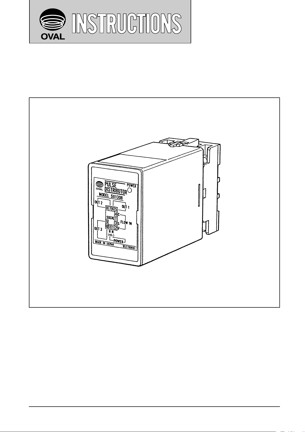
PULSE DISTRIBUTOR
MODEL SU308
E-73-2-E
Every OVAL product is fabricated and shipped from our factory under stringent quality control
program. In order to maintain its design performance throughout the life of this distributor, this
manual oers the operator the necessary installation, operation and maintenance information.
Be well familiar with these instructions before you place the distributor in service and keep
this manual for your quick reference. It is suggested that you also familiarize yourself with the
instruction manuals
Page 2
E-73-2-E
2
CONTENTS
1.GENERAL .......................................................................................................................................................3
2. FEATURES ...................................................................................................................................................3
3. INSTALLATION ..........................................................................................................................................3
4. WIRING ..........................................................................................................................................................4
5. OVERALL BLOCK DIAGRAM ...............................................................................................................4
6. PREPARATION AND OPERATION ...................................................................................................5
7. QUICK TROUBLESHOOTING ..............................................................................................................5
8. INDIVIDUAL JUMPER SETTING .......................................................................................................6
8.1 ENCLOSURE REMOVAL ..................................................................................................................... 6
9. GENERAL SPECIFICATIONS ..............................................................................................................7
10. PRODUCT CODE EXPLANATION ..................................................................................................8
CONVENTIONS
Shown in this manual are the signal words NOTE, CAUTION and
WARNING, as described in the examples below:
NOTE: Notes are separated from the general text to bring
the user's attention to important information.
CAUTION: Caution statements signal the user about hazards
or unsafe practices which could result in minor
personal injury or product or property damage.
WARNING: Warning statements signal the user about hazards
or unsafe practices which could result in severe
personal injury or death.
Page 3
E-73-2-E
1. GENERAL
This distributor accepts a train of incoming pulses from the owmeter of most kinds, or other signal generating sources, shapes its wave form and, with desired pulse width, furnishes three sets
of mutually isolated outputs, isolated also from the input.
2. FEATURES
(1) Compactly built plug-in design. Easy to use and maintain.
(2) Provides a power supply to the pulse generator and preamplier (converter) of a variety of
owmeters.
(3) A free type power supply accepts 85-265VAC power source (or 20 to 30V DC in the DC version).
3. INSTALLATION
Installation Location
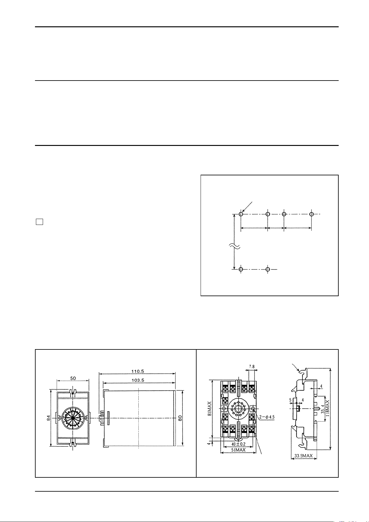
Select an installation location where
(1) Mechanical vibration, shock and corrosive
gases least exist.
(2) Air is dry and temperature at room temperature
and stable.
➡
NOTE: Although the manufacturer guarantees
stated performance at ambient temperatures
from -10 to +50℃ , it is recommended that the
min.140
instrument be placed in service in a room
temperature environment.
(3) Potential sources of inductive interference,
such as electromagnetic contactors, are located suciently away.
(4) A lightening arrestor is provided if incoming
Fig. 3.1 Socket Mounting Centers
signals are subject to potential influence of
lightening.
(5) In an application where two or more distributors are to be installed side by side, a sucient
working space is secured behind the instrument to facilitate wiring and maintenance (see Fig. 3.1).
(6) For use in an environment where noise level is high, we recommend to use commercially
available noise lters, isolation transformers, or similar devices.
Dimensions in millimeters
2-M4 Mounting Hole
min.
40 ± 0.240 ± 0.2
20
Fig. 3.2 Distributor Outline Dimensions
Lock Lever
Terminal Screw: 11-M3.5 × 7
Fig. 3.3 Socket Outline Dimensions
3
Page 4
E-73-2-E
J2
J1 J4
J3
OPEN:0.3to12ms
CLOSE:5to250ms
1
2
P1
Pulsewidthadjust
(MM:Pulsewidthadjustcircuit)
1:1waveshape
circuit
MM
DCpowertopulsegenerator
DCpowertothelogics
2,3,4
11,1
FLOWIN
POWER
5,6
7, 8
9,10
OUT1
OUT2
OUT3
TP2
TP1
1
2
OPEN:One-shot
CLOSE:Uppercutoff
Generatorselect
circuit
Powersupply
circuit
4. WIRING
(1) Separate eld wiring from other power lines
or power circuits to minimize the possibility
of inductive interference.
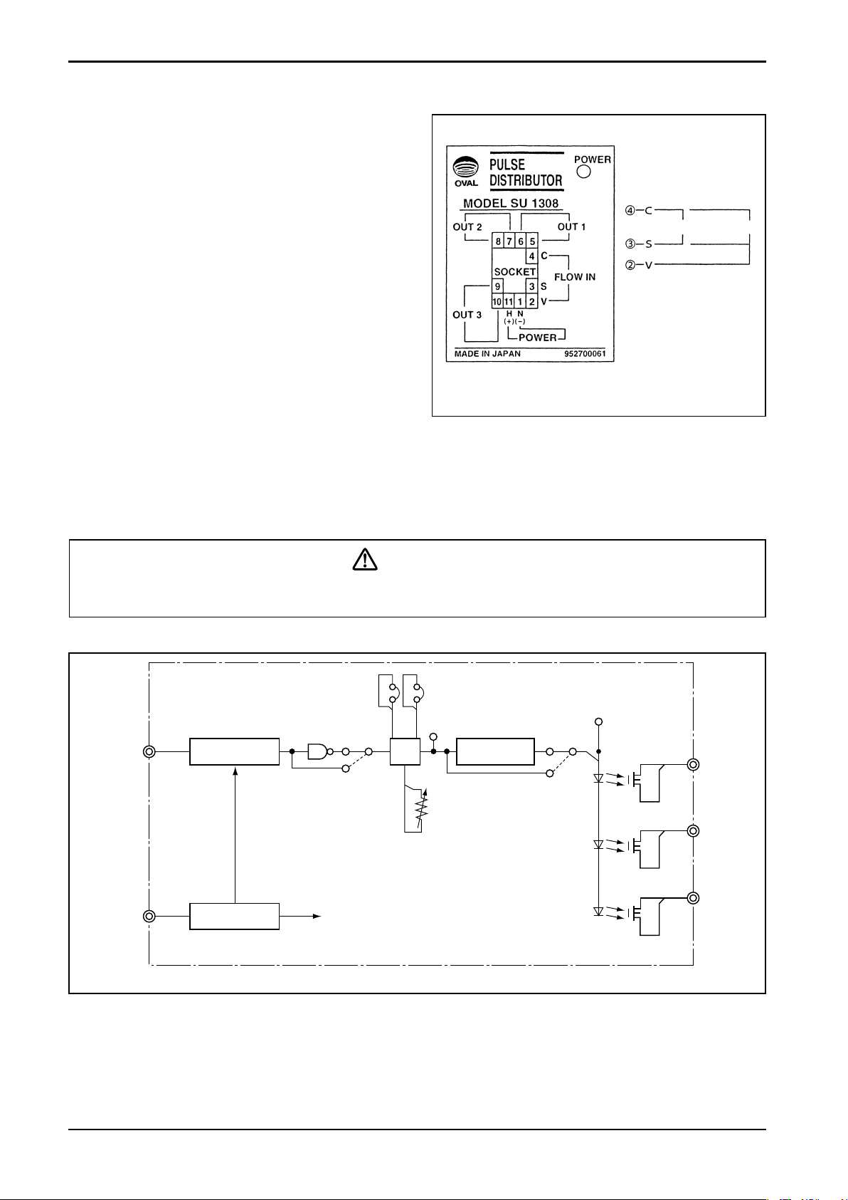
(2) Terminal arrangement is shown in Fig. 4.1.
(3) M3.5 ×7 screws are used for terminals.
Ensure good electrical connections.
(4) Upon completion of wiring connections,
install the distributor body into the socket.
Then engage the locking levers on the
socket assembly with the distributor body.
(5) For incoming signal cables from the owme-
ter or other signal sources, cables recom-
mended for the instrument of interest must
be used. Transmission length also depends
on the specication of that instrument.
For ot her s i gnal c ables, e l ectros t ati-
c a l l y - shielded, poly ethylene-insulated,
vinyl-sheathed control cables (CEVS 1.25
to 2.00mm2, 2- or 3-conductor), or equiv-
alent, must be used. With a conductor area
2 mm2, the maximum transmission length is
one kilometer.
Wiring Connections
● FLOW IN terminals
2-wire sig. 3-wire sig.
● OUT1, OUT2, OUT3
Polarity observation
is not required.
Fig. 4.1 Terminal Identication
CAUTION
Make electrical connections upon conrmation of validity of owmeter (pulse generator) and receiving instrument combination by their model No., serial No., etc.
5. OVERALL BLOCK DIAGRAM
● Description of Individual Circuits (by block)
● Pulse generator select circuit
………Selects the acceptable signal type of pulse generator and shapes the waveform.
● Power supply circuit……………Furnishes power of required voltage to individual circuits.
● Pulse width adjust circuit ……Selects the “ON” duration of output pulse signals OUT 1, 2, and 3.
●
1:1 waveshaping circuit………Adjusts the ON/OFF ratio of output signals OUT 1, 2, and 3 to 1:1.
Fig. 5.1
Page 5
E-73-2-E
PowerIndicatorLED(red)
PL1
P1
0VA
0VB
CLK
TP2
TP1
J1
1
2
J5
1J42
J2
J3
Selectorboard
45590 1□0□
Powersupplyboard
45500 4□01
Distributorboard
45500 4603
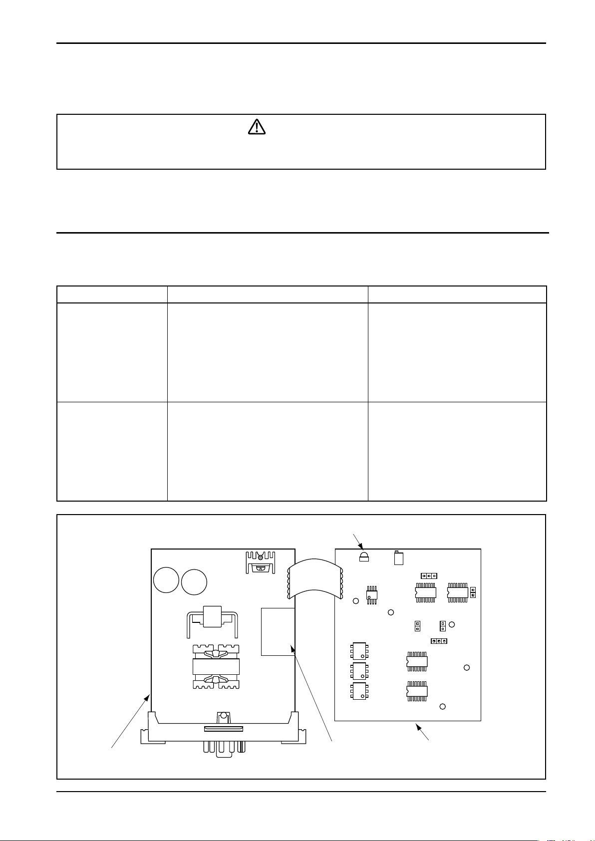
◆InternalComponentLocations
6. PREPARATION AND OPERATION
(1) Ensure that the pulse distributor and related equipment are correctly installed and wired with
no place left unnished.
WARNING
Make sure to see that the power terminals are connected to a power source of the
rated voltage. Applying a power of incorrect voltage could ruin your instrument.
(2) Supply power to this instrument and make sure to see that the power indicator (red LED)
comes on.
(3) Initiate operation by allowing the uid to run.
7. QUICK TROUBLESHOOTING
● If the trouble is suspected to be internal to the distributor, seek our service.
Symptom Check Possible Causes
Power indicator lamp
(LED) fails to come on.
No pulse output. 1. Input signal line correctly wired?
1. I nspe ct the p ower sup p ly b oard .
Is p owe r s our ce type (AC /DC ) i n
co nformit y with the p ow er supply
board?
2. Make sure of power source voltage. Is
an 85 to 246VDC (50/60Hz) power or
20 to 30V dc power Impressed across
terminals 11 (+) and 1 ( − )?
2. Input signal coming in?
3. Pulse generator valid on the pulse
generator select board ?
1. Power supply board is improper.
2. Line voltage is improper.
3. A fault In the internal power
board.
1. Input wiring is incorrect.
2. Pulse generator is at fault.
3. Pulse generator select board is
incorrect.
4. Power supply boa rd or p ulse
g e n e r a t o r s e l e c t b o a r d or
distributor board in the internal
assembly is at fault.
Fig. 7.1
Page 6
E-73-2-E
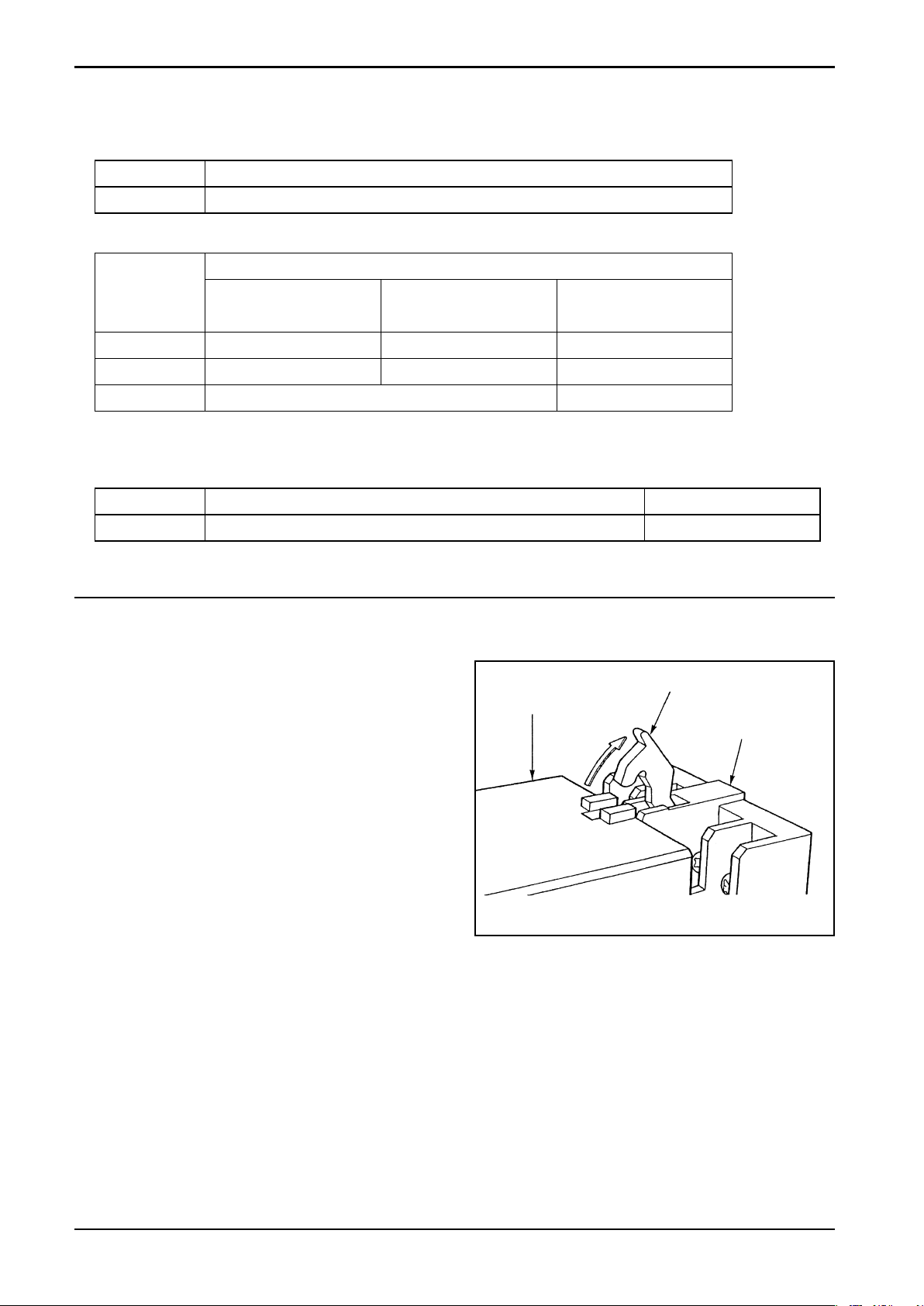
8. INDIVIDUAL JUMPER SETTING
● Input Setting: Establish input pulse mode.
Jumper Input pulse mode (pulse generator)
J1 Voltage pulse (Code 3 only): 2 Others: 1
● Output Setting: Establish output mode.
Output mode
Jumper
One-shot output Upper cuto output
J2 OPEN CLOSE OPEN
J4 2 2 1
J5 OPEN CLOSE
● Output Pulse Width Setting and Adjustment:
Establish parameters such as “ON” width or cuto width of output pulse signal.
Jumper Pulse width adjust range (adjustable with P1) Location
Duty sync with input
1:1 output
J3 OPEN:0.3 to 12ms CLOSE:5.0 to 250ms TP1and 0VB
(If output mode is “Duty sync with Input 1:1”, it adjustment is correct at 1 ms. )
8.1 Enclosure Removal
(1) Unlatch the locks of socke t ass embly ,
separate the distributor body and remove
the enclosure (see Fig. 8.1).
(2) Referring to the pictorial drawing showing
component locations (Fig. 7.1) on page 5,
make adjustments required.
Enclosure
Fig. 8.1
Lock Lever
Surface Mount
Socket
Page 7
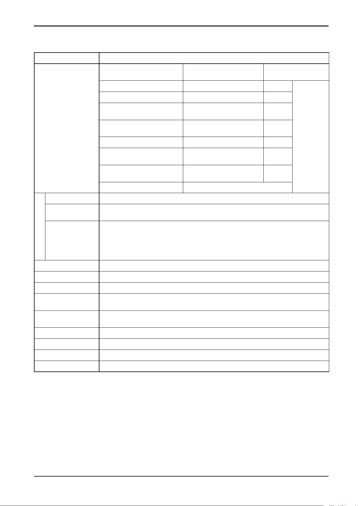
9. GENERAL SPECIFICATIONS
Item Description
Pulse Type
8V 2-wire current pulse OPTO 01, 02 8.5VDC
Contact-closure pulse PG20 13.5VDC
2-wire, 12VDC 3-wire
voltage pulse
Input signal
24VDC 2-wire current pulse
(4/20mADC)
12VDC 2-wire current
Open collector pulse
32VDC 3-wire open
collector pulse
Frequency response 500Hz Max. (50Hz max. with PG20)
Companion Pulse
Generator
PG30, NPG60A(F) 13.5VDC
PA14, 15, 25, NPG60A(E) 24.0VDC
pulse PG30S 13.5VDC
FLOWPET-EG, NPG60A (E3),
MOS-FET
PA11 32.0VDC
Power to Pulse
Generator
13.5VDC
E-73-2-E
Current
capacity
40mA max.
approx.
(Shortcircuit
protection
circuit
provided)
Signal Open MOS-FET, 3 outputs
Capacity
Output pulse
Output signal
width
Power source 85 to 264VAC 50/60Hz or 20 to 30VDC
Power consumption 8VA approx.
Ambient temperature - 10 to + 50℃
Insulation resistance
Withstanding voltage
Mounting Plug-in type
Enclosure Plastic molding, black
Weight 0.5 kilogram approx.
Accessory furnished 11-pin surface mount socket, quantity one
230VAC/340VDC 0.2A
Resistance during ON: 16 Ω max. Leakage current during OFF: 1 μ A max.
One-shot 1ms, 50ms
Upper cuto in width of pulses sync with input 10ms, 100ms
Duty sync with input 1:1
(Corresponds to output frequency range 4 to 200Hz. Below 4Hz,
100ms one-shot)
Across power terminals tied together and output terminals tied together:
10M Ω min. (500VDC insulation resistance tester)
Across power terminals tied together and output terminals tied together:
1500VAC for one minute. With DC power: 1000VAC for one minute
7
Page 8
E-73-2-E
Allspecificationsaresubjecttochangewithoutnoticeforimprovement.
OVAL Corporation
Head Office: 10-8, Kamiochiai 3-chome, Shinjuku-ku, Tokyo, Japan
Phone. 81-3-3360-5121 Fax. 81-3-3365-8605
2011.01 Revised
2009.12 Revised
2006.03 Revised△
2004.08 Released
E-713-2-E
(3)
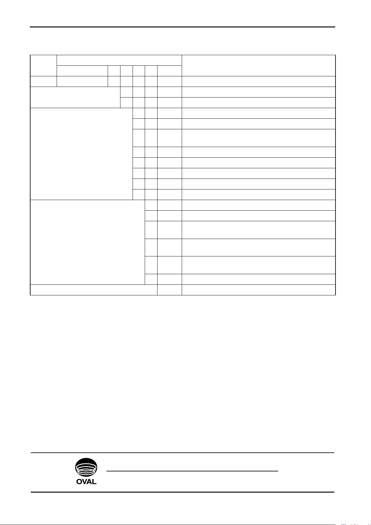
10. PRODUCT CODE EXPLANATION
Item
① ② ③ ④ ⑤ ⑥ - ⑦ ⑧ ⑨ ⑩ ⑪ ⑫
Model S U 1 3 0 8 - Pulse Distributor
Power
Flow Input
Output Pulse Width
Product Code
6 20 to 30VDC
7 85 to 264VAC 50/60Hz
1 8VDC 2-wire current pulse
2 Contact-closure pulse
3
4 24VDC 2-wire current pulse (4/20mADC)
5 12VDC 2-wire current pulse
6 Open collector pulse
8 32VDC 3-wire open collector pulse
9 Other than above
1 Pulse width 1ms
2 Pulse width 50ms
3
4
5
9 Other than above
2-wire voltage pulse and 12VDC 3-wire voltage
pulse
Sync with input
Upper cuto in width of pulses 10ms
Sync with input
Upper cuto in width of pulses 100ms
Sync with input
Duty 1:1 output (Response 200Hz max.)
Description
000 Always“000”
 Loading...