

Page 1
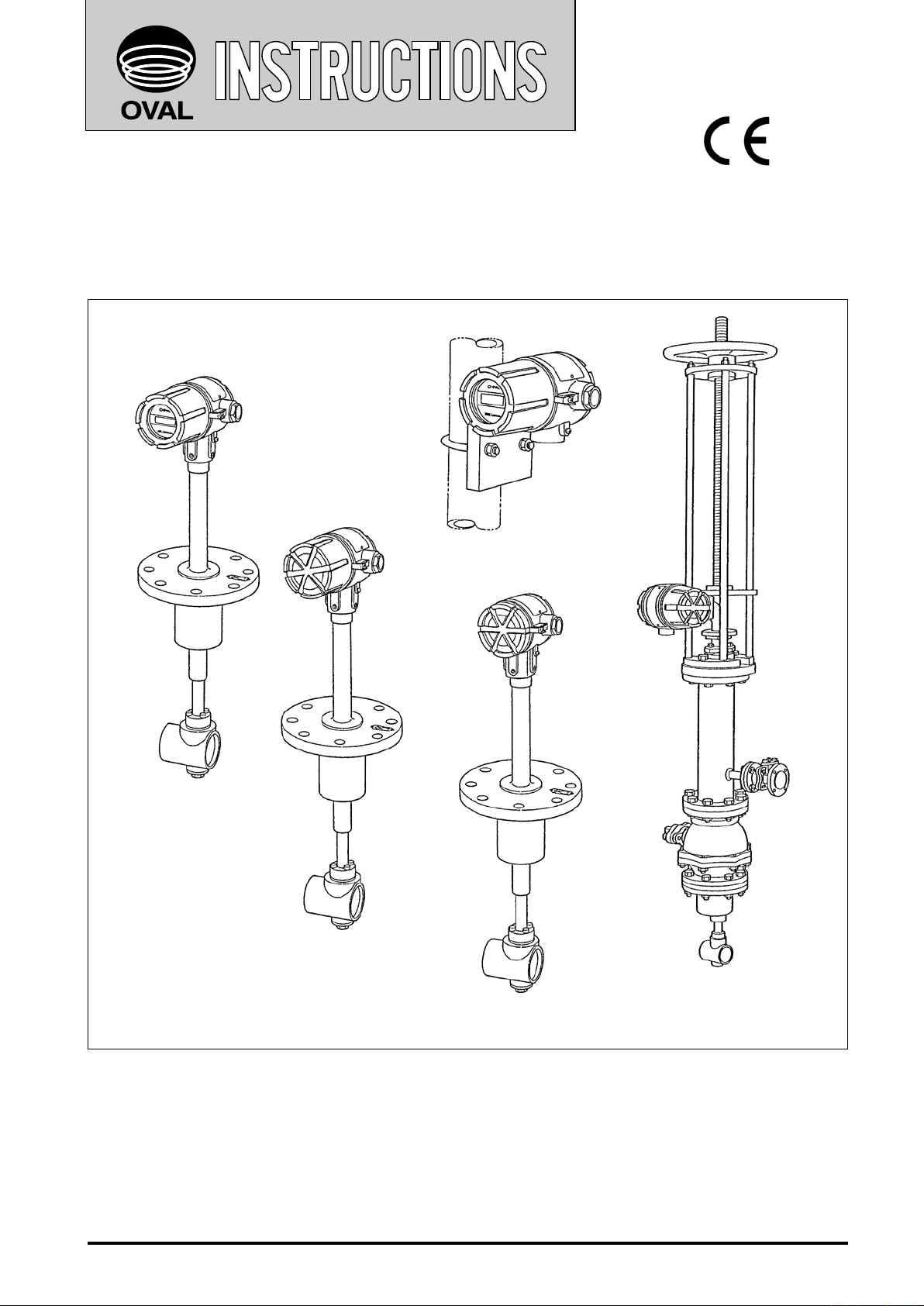
Vortex Flowmeter
Smart EX DELTAⅡ
Ins. No.
D-582-3-E
(Insertion type, xed)
(Retractable, hottap type)
Totalizer provided
Separately-mounted
preamp with totalizer
Less Indicator
Hottap type
Separately-mounted sensor
Every OVAL Smart EX DELTAⅡ is fabricated and shipped from our factory under stringent quality
control. In order to maintain its design performance throughout its life, this manual offers the
operator the necessary installation, operation and maintenance information. Be well familiar with
these instructions before you place the meter in service and keep this manual for ready reference.
1
Page 2

D-582-3-E
CONTENTS
1. BEFORE YOU BEGIN ............................................................................................................ 5
1.1 Confirming the Specifications ................................................................................................ 5
1.2 Transit Considerations ........................................................................................................... 5
1.3 Storage Considerations ......................................................................................................... 5
2. OPERATING CONDITIONS .................................................................................................. 5
3. GENERAL ................................................................................................................................ 6
4. COMPONENT NAMES AND FUNCTIONS ....................................................................... 6
5. PIPING INSTRUCTIONS ....................................................................................................... 9
5.1 Standard Piping Conditions ................................................................................................... 9
5.2 Pipes to be Used .................................................................................................................. 10
5.3 Location of Pressure Gage and Thermometer Taps ............................................................. 10
5.4 Pulsation ............................................................................................................................... 10
5.5 Prevention of Cavitation (liquid service) ............................................................................... 10
5.6 Prevention of Excessive Flowrate ........................................................................................ 11
5.7 Prevention of Slug Flow ....................................................................................................... 11
5.8 Keep the Pipe Filled with Fluid ............................................................................................. 11
5.9 Bypass Line .......................................................................................................................... 11
6. INSTALLATION .......................................................................................................................12
6.1 Installation Locations ............................................................................................................ 12
6.2 Physical Orientation ..............................................................................................................12
6.3 Installation Procedure, Fixed Type ........................................................................................ 13
6.3.1 Typical Orientation .......................................................................................................... 13
6.3.2 Installation Procedure......................................................................................................13
6.4 Installation Pro, Hottap Type .................................................................................................14
6.4.1 Part Names .................................................................................................................... 14
6.4.2 Installation Procedure......................................................................................................15
6.4.3 Preamplifier Orientation...................................................................................................16
6.5 Lagging Work ....................................................................................................................... 16
6.6 Ambient Temperature ............................................................................................................ 17
6.7 Partially Filled Pipe ................................................................................................................17
6.8 Working Stage and Hoist (hottap type)................................................................................. 17
6.9 Drive Unit Removal of Hottap Type ....................................................................................... 18
6.10 How to Change Preamplifier Orientation .............................................................................19
6.11 How to Change Display View Angle of Totalizer ................................................................. 20
6.12 Separately-mounted Preamplifier Installation ......................................................................21
7. WIRING CONNECTIONS ......................................................................................................22
7.1 Wiring Specifications ............................................................................................................. 22
7.2 Preamplifier Terminal Identification........................................................................................ 22
7.3 Considerations on Wiring Connections .................................................................................22
7.4 Separately-mounted Preamp to Sensor Terminal Box Wiring Connections .......................... 23
7.5 Terminal Box Cover Removal ................................................................................................ 23
7.6 Hookup with Receiving Instruments ...................................................................................... 24
7.7 Diagrams Showing Typical Wiring Connections (example) ................................................... 25
2
Page 3

D-582-3-E
8. OPERATION ............................................................................................................................ 26
8.1 Flushing the Piping Assemble ............................................................................................... 26
8.2 Operation Procedure ............................................................................................................. 26
9. FLOW SENSITIVITY ADJUSTMENT PROCEDURE ....................................................... 27
9.1 Amplifier Gain ........................................................................................................................27
9.2 Trigger Level .......................................................................................................................... 27
10. PARAMETER SETUP ..........................................................................................................28
11. BUILT-IN DISPLAY FUNCTIONS AND OPERATION
(totalizer equipped model) .............................................................................................. 30
11.1 Display Selection (Totalizer equipped model) ...................................................................... 30
11.2 Total Flow Reset .................................................................................................................. 30
12. PRECAUTIONS ON PULSE TYPE ....................................................................................31
13. PREAMPLIFIER RUN CHECK WITH SIMULATED PULSE INPUT ...........................32
13.1 Test Setup ............................................................................................................................ 32
13.2 Full Scale Freq. Calculation ................................................................................................33
14. MAINTENANCE .................................................................................................................... 34
14.1 Disassembly and Inspection ................................................................................................34
14.2 Disassembly and Inspection Procedure .............................................................................. 34
14.3 Preamplifier Inspection ........................................................................................................ 36
14.3.1 Description of Test Pins ...............................................................................................36
14.3.2 Switch and Potentiometer Settings..............................................................................37
14.3.3 Preamplifier Block Diagram ......................................................................................... 38
14.4 Display Installation ..............................................................................................................39
15. EXPLODED VIEW AND PARTS LIST, FIXED TYPE .....................................................40
16. ASSEMBLY DRAWING AND PARTS LIST, HOTTAP TYPE ........................................ 42
17. GENERAL SPECIFICATIONS ...........................................................................................44
17.1 Sensor Specifications .......................................................................................................... 44
17.2 Preamplifier Specifications .................................................................................................. 45
17.3 Nominal Meter Factors ........................................................................................................ 46
17.4 Pressure Losses ..................................................................................................................47
18. OUTLINE DIMENSIONS .....................................................................................................48
18.1 EX DELTAⅡ ........................................................................................................................ 48
18.2 Separate-Mount Preamplifier ..............................................................................................50
18.3 Flow Straightener and Downstream Pipe ............................................................................ 50
19. FLAMEPROOF APPROVAL : DIMENSION OF NON-THREADED JOINTS ............ 51
20. PRODUCT CODE EXPLANATION ...................................................................................52
■ NOTES ON EXPLOSION-PROOF TYPE FOR CHINA (NEPSI) ................................... 53
3
Page 4
D-582-3-E
CONVENTIONS
Shown in this manual are the signal words NOTE, CAUTION and
WARNING, as described in the examples below:
NOTE: Notes are separated from the general text to bring the
user's attention to important information.
CAUTION: Caution statements signal the user about hazards or
unsafe practices which could result in minor personal
injury or product or property damage.
WARNING: Warning statements signal the user about hazards or
unsafe practices which could result in severe personal
injury or death.
4
Page 5
D-582-3-E
DELTA F LOW MET ER
OVAL Corporation
MADE IN JAPAN
MODEL
SER. No.
MAX. TEMP.
MAX. PRESS
DATE
TAG.No.
METER FACTOR
FACTORD PULSE
ANALOG F.S.
AMB. TEMP.
m3/h
L/P
/P
( )
Hz
°
C
°
C
①
②
③
④
⑤
⑥
⑦
⑧
⑨
⑩
⑪
⑫
⑬
RATEDMAX.FLOW
1. BEFORE YOU BEGIN
1.1 Confirming the Specifications
(1) When received, the meter should be thoroughly inspected for indication of rough handling during
transit.
(2) Product code number and ratings are stated on the meter nameplate. Make sure that the ratings
shown conform to your particular specifications.
1.2 Transit Considerations
(1) It is desirable that the meter be transported to the installation site in the shipping container used for
transit from the factory.
(2) During transportation, exercise care to avoid impact shock and rainwater.
1.3 Storage Considerations
(1) The meter can best be stored in the shipping container used for transit from the factory.
(2) The place of storage should meet the following requirements:
● Free from rain and water
● Free from vibration and impact shocks
● With least temperature and humidity variation (around 25℃ and 65% R.H.)
(3) A meter that has once been placed in service for any length of time should be washed clean to remove
residue metered material completely from its inner walls before storage. Waterproofing the cable
entrance should also
CAUTION:
Unauthorized modification will invalidate the specifications.
be taken into consideration.
2. OPERATING CONDITIONS
(1) This flowmeter is developed, designed, and manufactured to be used as a flowmeter for general industrial
application. Therefore, when it is used for the application where its operation is directly related to the
safety of the relevant system or where the product is important in the facilities (such as process control
and custody transfer), you are requested to secure sufficient safety including safety design, redundancy
and duplication of the process, and implementation of periodic inspection. Do not use this flowmeter in the
case where its operation and performance is directly related to human life.
(2) If this flowmeter is used under appropriate conditions, it can demonstrate its stable performance without
aging degradation of accuracy. However, malfunction or failure may occur due to various factors. Thus,
considering the operating conditions, operating status, and importance in the process, you should study
the cycle of periodic maintenance and its items of your flowmeter. In order to secure long-term and safe
use, OVAL recommends the customer to verify the soundness of the flowmeter through periodic inspection
every two years. For the details of inspection, contact our sales agent or person in charge.
(3) This flowmeter is manufactured, adjusted, and inspected to meet the conditions of use. The fluid
measured, flow range, pressure, temperature, or the like must be applied under the specified conditions.
The conditions for use are stated in the nameplate attached to the flowmeter transmitter and specification
sheet supplied with the product.
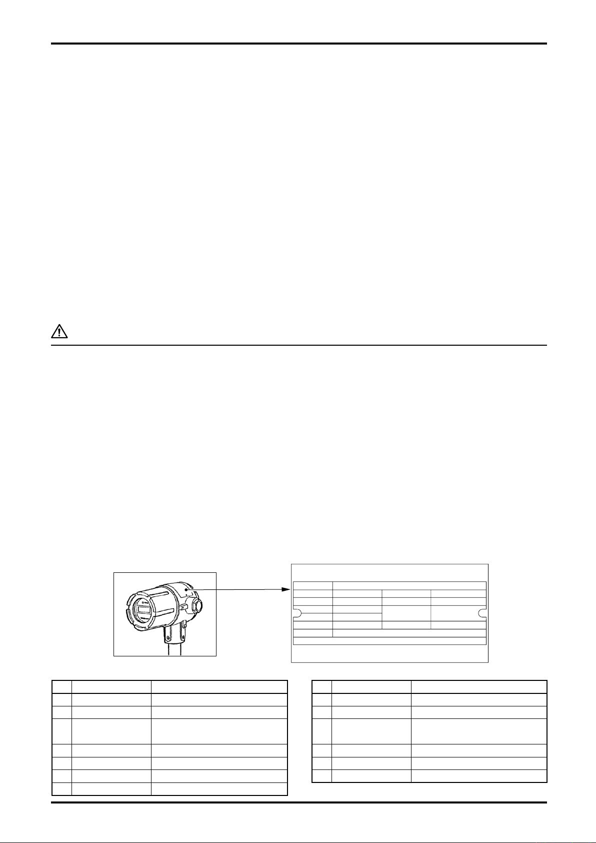
Items Stated on the Nameplate
No. Item Description No. Item Description
① Model
② Serial No.
Rated Max.
③
Flow
④ Max. Temp.
⑤ Max. Pressure
⑥ Date
⑦ Meter Factor
Max. flowrate stated in the
catalog in actual flowrate.
Unfactored pulse unit in pulse out.
―
―
―
―
―
⑧
Factored Pulse Unit
Not stated for analog output.
⑨ Analog F. S. Not stated for pulse output.
Full Scale
⑩
Freq.
⑪ Ambient Temp.
Full scale frequency established.
Not stated for pulse output.
Max. allowable ambitent temp.
⑫ Tag No. Stated only where specified.
⑬ Remarks Stated only where specified.
5
Page 6

D-582-3-E
3. GENERAL
EX DELTAⅡ is a vortex flowmeter, making use of a piezoelectric sensor. Behind the bluff body in a
flowing fluid, von Karman vortices form and shed proportional to the rate of flow on alternating side of the
bluff body placed perpendicular to the stream of flow. A piezoelectric sensor picks up the frequency of
these vortices, which is used for flowrate measurement.
By detecting the flowrate of a section representative of the total flow across the pipeline with a probe
inserted into the pipeline, this insertion type EX DELTAⅡ measures the total flowrate. This type of meter
is ideally suited for flow measurements in large diameter lines.
The probe measures 50 millimeters in nominal diameter and consists of a bluff body containing a
piezoelectric sensor. Depending on the way the probe is installed in the main pipe, two types are
available: fixed and hottap. The latter design allows sensor inspection and replacement without
interrupting the process flow in the line.
This meter is full of intelligent features to review, set up, change compensated calculations, ranges,
parameters, with self diagnostics and loop test capabilities through communications with OVAL Smart
Communication Unit (Model EL2310) and general-purpose Windows PC.
Features
(1) A broad flow range with high metering accuracy.
(2) The sensor isolated from the process fluid and simple meter design with no moving parts contributes
to long life.
(3) No loss of accuracy with age.
(4) A wide temperature and pressure range. Accepts most fluids, including liquids, gases and steam.
(5) Small pressure loss across the meter saves energy.
(6) Pipeline closure is not required in the event of an emergency.
(7) Output being pulses proportional to flow velocity makes totalization simple.
(8) Economy is evident when it comes to flow measurements in large diameter pipelines.
4. COMPONENT NAMES AND FUNCTIONS
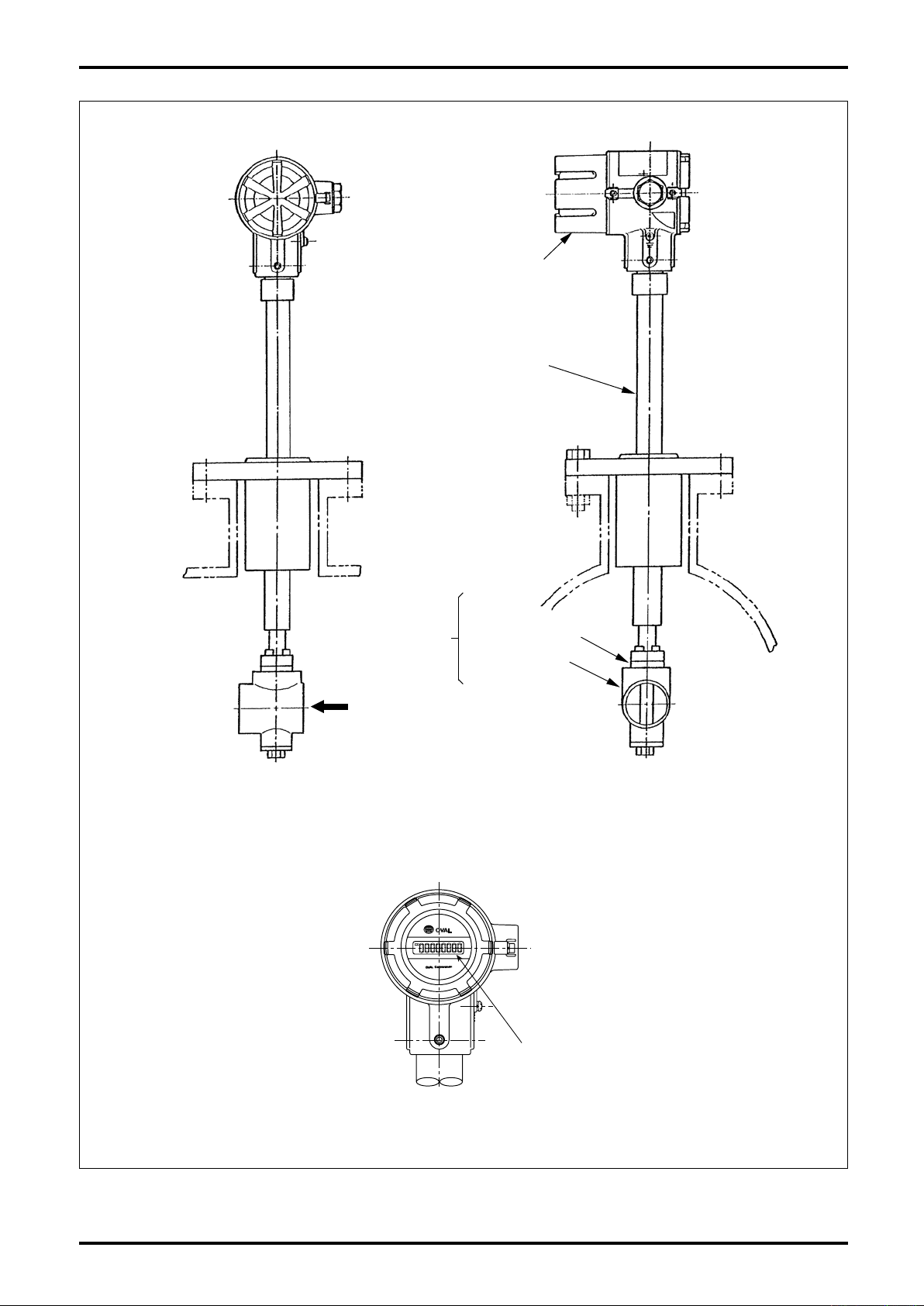
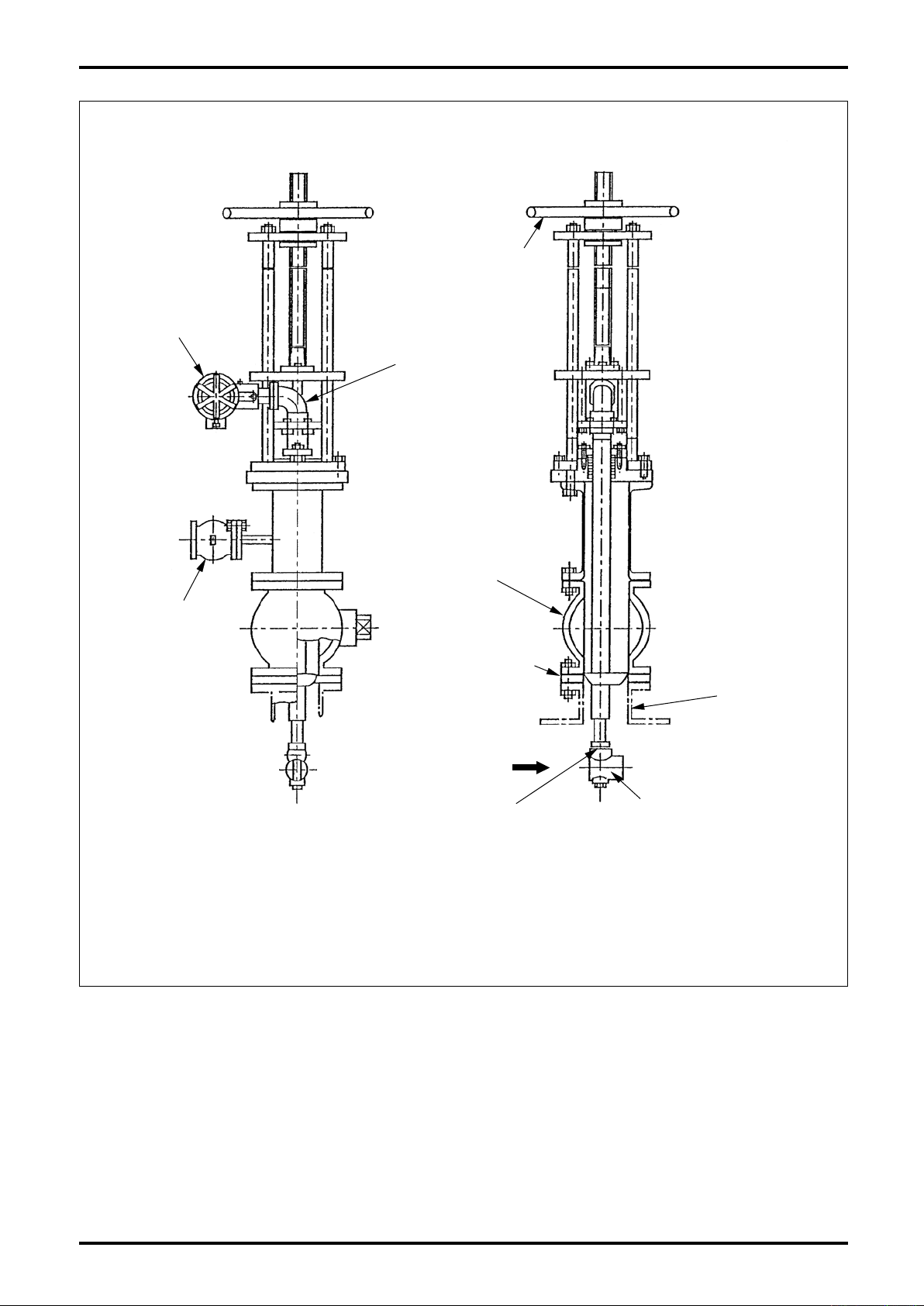
Refer to Figs. 4.1 and 4.2 on the next page.
① Meter Body (probe):
Consists of a measuring pipe and a vortex shedding body (bluff body). As the metered material flows,
von Karman vortices form and shed behind the bluff body.
② Sensor (vortex sensing element):
Has a built-in piezoelectric sensor. All wetted parts are made of stainless steel for maximum life
expectancy.
③ Adapter (shaft assembly):
Connects the meter body with the preamplifier. To be installed on the pipeline with a flange. Also
serves to protect the sensor and dissipate heat.
④ Preamplifier:
Transforms changes in electric charges generated from the sensor into an output signal representing
the flowrate. Consists of the interface board, amplifier board, isolation board, CPU board, and display.
Output comes in five types-current pulse (factored/unfctored), open collector pulse (factored/
unfctored) and analog output.
⑤ Preamplifier PA25S (totalizer and digital indicator):
Physical orientation of the preamplifier is adjustable in steps of 90 deg. around the adapter axis (see
Sec. 6.10 on page 19). The display can also be oriented in steps of 90 deg. within the preamplifier
housing.
6
Page 7
8-digit LCD Totalizer
④ Preamplifier
(PA25)
③ Adapeter
D-582-3-E
② Sensor
Probe
Flow Direction
⑤ Preamplifier PA25S(Totalizer, Digital Indicator)
(vortex pickup)
① Meter Body
(probe)
Fig. 4.1 Component Names, Fixed Type
7
Page 8
D-582-3-E
④ Preamp
Handwheel
③ Adapter
Vent Valve
Gate Valve
Hold-Down Disc
Flow Direction
② Sensor
(Vortex Pickup)
Fig. 4.2 Part Names, Hottap Type
Mounting
Nozzle
① Meter Body
(Probe)
8
Page 9
D-582-3-E
12D
Flow
15D min.
Flow
23D min.
Flow
25D min.
Flow
40D min.
Flow
15D min.
Flow
Fully open
50D min
Flow
Partially open
5. PIPING INSTRUCTIONS
For general consideration, see JIS Z 8766, "Flowrate Measurement Methods with Vortex Flowmeters".
5.1 Standard Piping Conditions
It is generally required that the flow pattern of a material moving into an inferential type meter be as
uniform as possible for accurate metering. Accordingly, proper flow straightening measures must be
taken when the application engineer considers installation of a DELTA meter. In applications where OVAL
straightening devices (flow straightener, and downstream pipe) are used, a straight pipe section is not
required unless otherwise specified. But if you plan to solve the flow pattern problem with a straight pipe
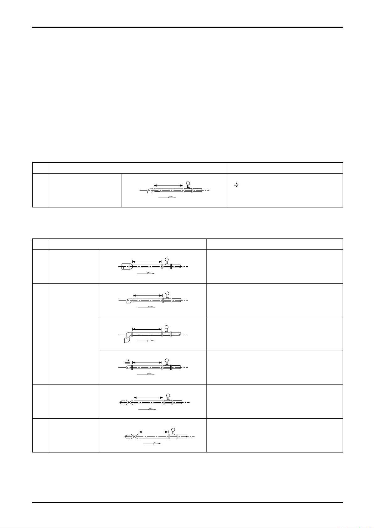
section alone, secure the length of a straight pipe conforming to the ISO standards given in Table 5.1
below:
(1) OVAL flow straightener combined with downstream pipe
No. Remarks
D=Nom. Dia.
1 Flow Straightener
See page 50 for face-to-face
dimension.
(2) Straight pipe alone without flow straightener
Table 5.1 Straight Pipe Lengths Recommended by ISO-5167 D=Nom. Dia.
No. Remarks
1 Reducer
A concentric reducer is upstream of meter.
An elbow is upstream of meter.
2 Elbow
Two elbows are horizontally upstream of
meter.
3
4
Gate Valve
Fully Open
Gate Valve,
Partially Open
Two elbows are vertically upstream of meter.
A full-open gate valve is upstream of meter.
A partially open gate valve, a narrow orifice,
or something that considerably disturbs the
flow pattern is upstream of meter.
9
Page 10
D-582-3-E
Meter Body
Flow
Direction
Gage Tap
Thermometer Tap
2 to 7D
φ 6
D= Nominal dia.
5.2 Pipes to be Used
Pipes having the inside diameter specified at the time you placed an order for this meter should be used
for upstream and downstream pipes. Otherwise, consult the factory for compatibility.
5.3 Location of Pressure Gauge and Thermometer Taps
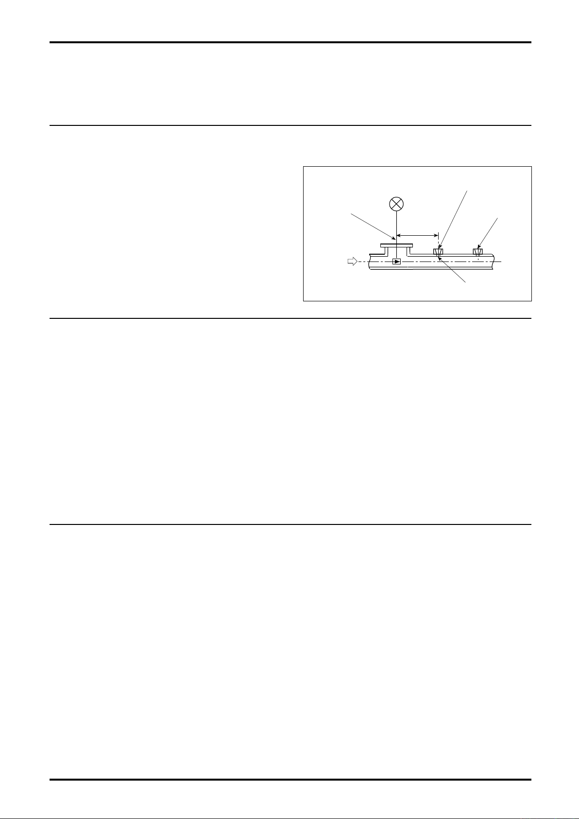
Taps for the pressure gauge and/or thermometer,
if d esired, shou ld be located d ownstream o f
the flowmeter as illustrated in Fig. 5.1 at right.
Therm o m eter tap s h ould b e lo c ated o n th e
downstream side of pressure detection and, at the
same time, upstream of the control valve.
Fig. 5.1
5.4 Pulsation
Compressors, Roots blowers and other pulsation pressure generating sources could adversely affect
meter performance. Minimize pulsating pressures by referring to the following formula:
N <7.2 ρV2 (Pa)
where N : Pulsation pressure (Pa)
ρ: Density (kg/m3)
V : Minimum velocity (m/s)
If pulsation pressure is excessive, the following measures should be taken into consideration:
① Locate the source of pulsation downstream of the meter or locate it as far from the meter as possible.
② Provide a pulsation attenuator, such as a chamber or pulsation snapper.
③ Shut off valves upstream and downstream of the meter when fluid flow is interrupted (as a precaution
against erratic signal generation at zero flow).
5.5 Prevention of Cavitation (liquid service)
To prevent cavitation, line pressure should be maintained above the level calculated by the following
formula:
P≧2.60ΔP+1.25P0 (MPa abs.)
where ΔP: Pressure loss (MPa) (See page 48.)
P0: Steam pressure of liquid (MPa abs.)
ρ: Density (kg/m3)
V : Flow velocity (m/s)
10
Page 11
P1
P2
P1 P2
Valve
Valve
Meter
Meter
Gauge
Gauge
Flow
Direction
Flow
Direction
5.6 Prevention of Excessive Flowrate
MeterUpstream Valve Downstream Valve
Valve in Bypass Line
Flow
Direction
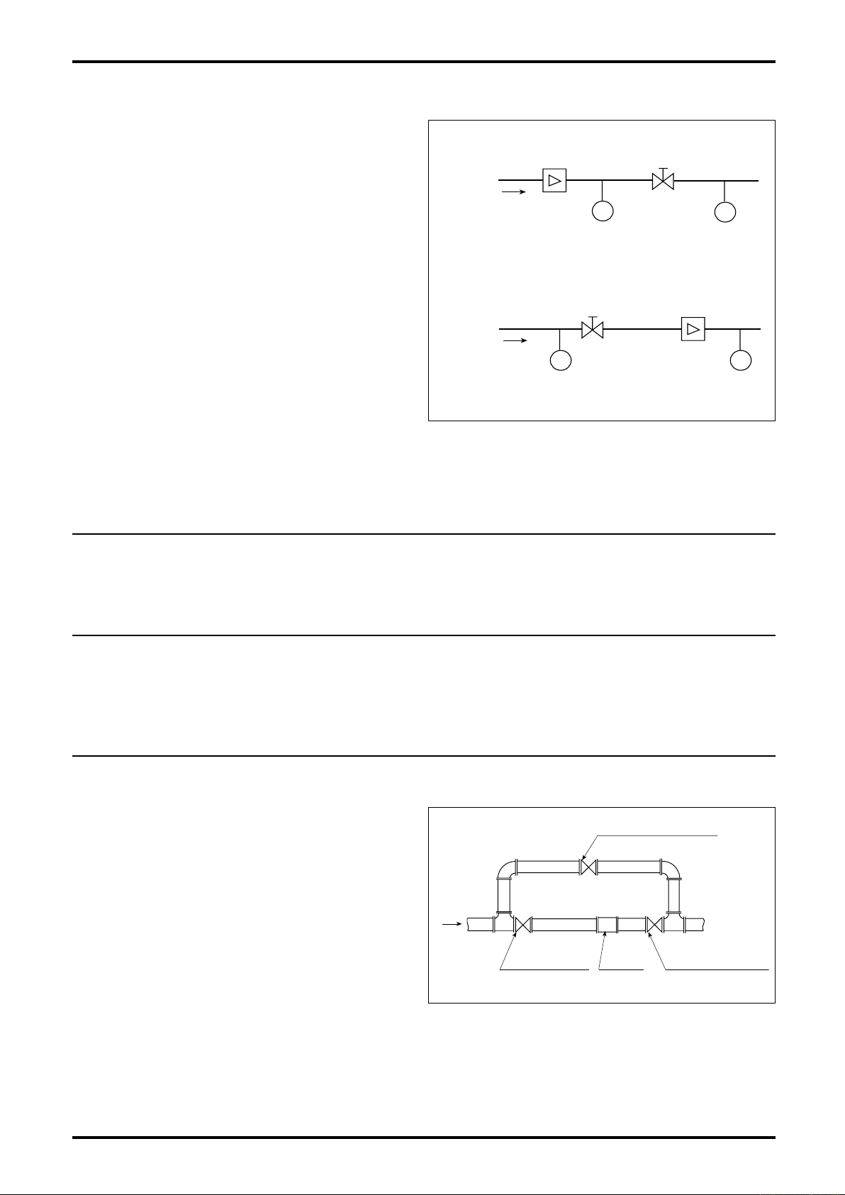
To ensure long meter life, transient flowrates
should be held below 1.6 times the meter's
maximum rating. Shown below are typical
examples in ste a m measure m e n t wher e
excessive flow is often encountered:
Examples where meter's maximum rating is
exceeded on a momentarily basis
D-582-3-E
「A」
In steam measurement
「B」
Whe n P1>P2, quickly o pening the v alve will
result in a fluid flow at a rate dependent on the
li ne resistance (mainly valve p ort position in
"A" or meter resistance in "B"). The resultant
rate of incoming flow is the sum of downstream
pipeline volume and consumption, but if pressure
Fig. 5.2
differential across the valve is great, the fluid
vel o ci t y w il l e a sil y r e ac h th e s oni c s p ee d ,
momentarily well in excess of meter's maximum
rating. (Such phenomenon is often experienced at
system startup or in batch operation.)
5.7 Prevention of Slug Flow
This meter can measure both gases and liquids, but slug flows (where gases exist in the process liquid)
will produce a loss of metering accuracy.
5.8 Keep the Pipe Filled with Process Fluid
When making a liquid measurement, ensure that the piping remains full of the process liquid. Installation
in locations where it is difficult to keep the piping filled with the process liquid, or where bubbles tend to
collect should be avoided.
5.9 Bypass Line
For maintenance and servicing purposes, it is a
good practice to provide a bypass line. Valves
upstream and downstream of the meter should be
of a design which will not disturb fluid flow pattern,
such as b all val v es ( full bor e typ e ), i n t h is
arrangement (see Fig. 5.3).
For general considerations to be observed,
refer to JIS Z 8766, "Flowrate Measurement
Methods with Vortex Shedding Flowmeters".
Fig. 5.3
11
Page 12
D-582-3-E
6. INSTALLATION
6.1 Installation Locations
Select a location with ambient temperatures -10 to +80℃ (or -10 to +60℃ for meters configured to
explosionproof rating). Installation in such locations as described below should be avoided:
① Hardly accessible for maintenance and servicing
② Temperature change and/or vibration is excessive
③ Possible immersion in water
④ Corrosive atmosphere
⑤ Unfit for the meter's explosionproof configuration
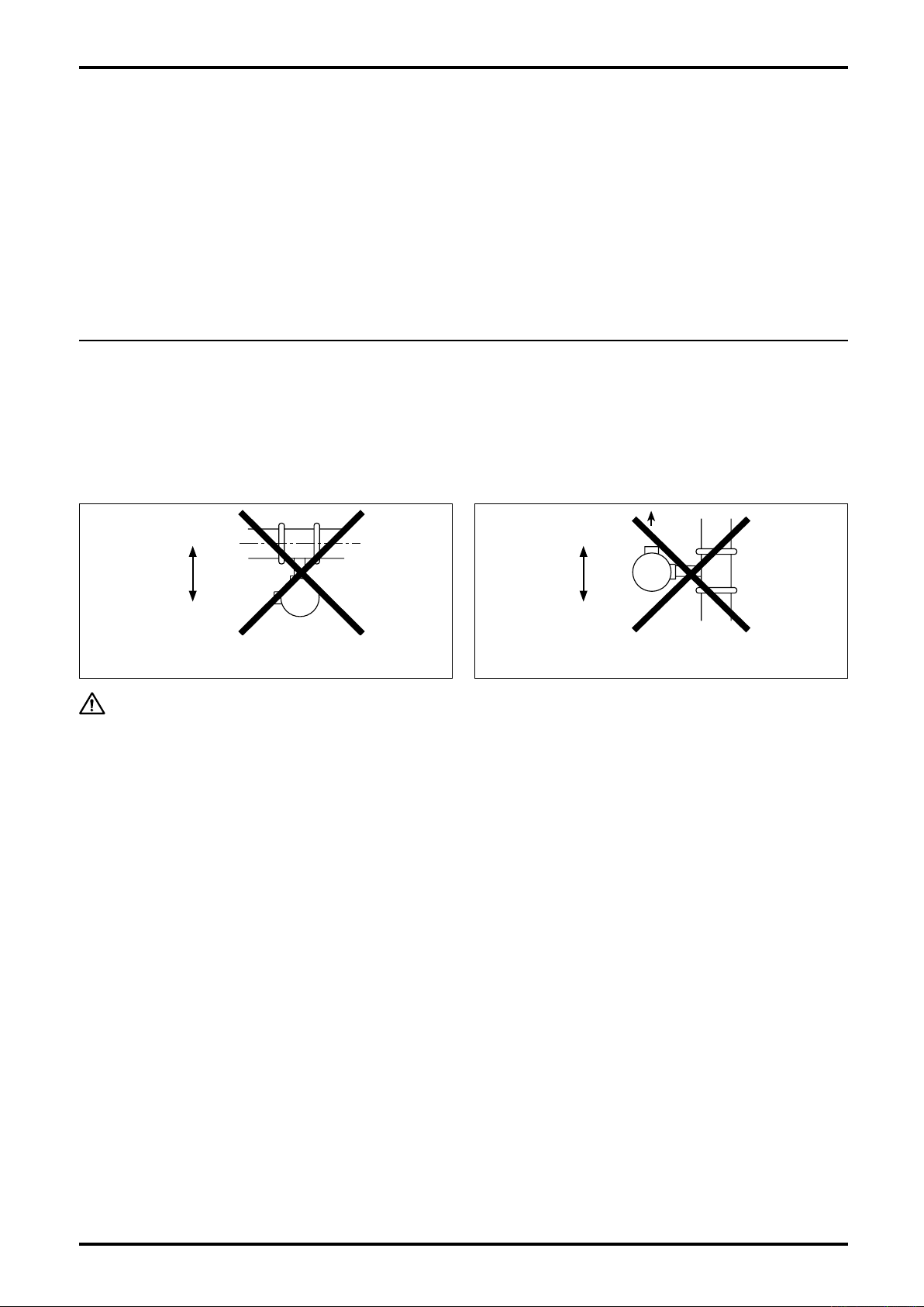
6.2 Physical Orientation
This meter may be installed either on a horizontal or vertical run. Avoid, however, such physical
orientation as:
① Inconvenient for inspection and maintenance
Top
Bottom
Fig. 6.1 Installed upside down
CAUTION:
The hottap type requires installation in a horizontal pipeline.
② Rainwater is ready to enter from cable entry
(if installed outdoors)
Top
Bottom
Fig. 6.2 Cable entry pointed upward
12
Page 13
D-582-3-E
6.3 Installation Procedure, Fixed Type
Install the meter body in the following manner:
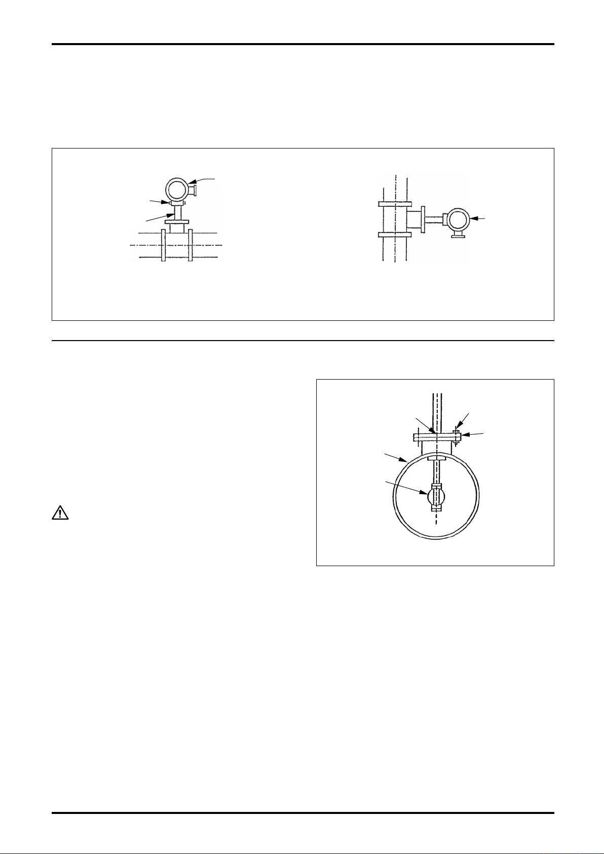
The piping may run either horizontal or vertical. Install the meter in a position illustrated in the sketches
below.
6.3.1 Typical Orientation
〈Horizontal Line〉
Preamp
Preamp Fitting
Screw
Adaptor
Flow Direction:Right→Left and Left→Right
6.3.2 Installation Procedure
Install the meter in the following manner:
① The meter probe body is provided with blind
ca ps. Be sur e to remove them before you
install.
② Determine the location by the flow direction
arrow mark and the center mark (V-groove) on
the shaft assembly (102).
③ Be sure to install the gasket.
Fig. 6.3
〈Vertical Line〉
Preamp
Flow Direction:Top→Bottom and Bottom→Top
V-Groove Mark
(Center Mark)
Pipe
Probe Body
Bolt
Gasket
CAUTION:
(1) Do not forget to install the gasket in place
and tighten bolts.
(2) A leak test should be conducted before
commencing operation.
Fig. 6.4
13
Page 14
D-582-3-E
6.4 Installation, Hottap Type
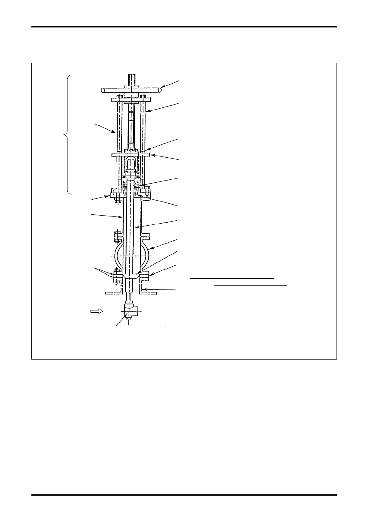
6.4.1 Part Names
Stud
Drive
Unit
Handwheel(Probe goes up or down as you turn it
in or out.)
Match Mark B(Indicates the probe is at the fully
raised position.)
Match Mark A(Indicates the probe is at the fully
inserted position.)
Guide
Packing Retainer
Cover
Short Pipe
(With Vent Valve)
Gaskets
Flow Direction
Gland Packing
Screw Axis
Gate Valve
Retaining Ring
Hold-Down Disc(Prevents noises caused by line
oscillation.)
Caution: Care should be taken
in the physical orientation.
Mounting Nozzle
Probe(Flowrate sensing assembly,consists of 2"
body, bluff body and sensor.)
Fig. 6.5
14
Page 15
D-582-3-E
6.4.2 Installation Procedure
(See assembly drawing in Fig. 6.5 on page 13 and Fig. 16.1 on page 43.)
By turning in or out the handwheel, the probe of this flowmeter goes down or up and, without the need of
interrupting the line, it can be drawn out. When the meter is placed in service for measurement, the holddown disc is so positioned as to come in contact with the retaining ring (the guide is at match mark "A" on
the stud).
During maintenance or inspection, allow the probe to be housed completely in the short pipe (the guide is
at match mark "B" on the stud) and remove the meter from above the gate valve.
When removing or installing it, exercise care to minimize the possibility of unexpected trouble by
observing the following instructions:
(1) Install the hold-down disc in the right physical orientation.
(2) As the probe passes through the opening in the gate valve, make sure that the gate valve is in its fully
opened position when the probe is inserted, and that the probe is hoisted completely above the gate
valve when the gate valve is closed before attempting to remove or install.
(3) Be aware of the internal pressure when you remove the flowmeter. (Allow the pressure to escape
through the vent valve before attempting to remove the meter.)
(4) Directions of handwheel rotation
Clockwise rotation (viewed from top) → Probe descends.
Counterclockwise rotation (viewed from top) → Probe ascends.
Installation Instructions
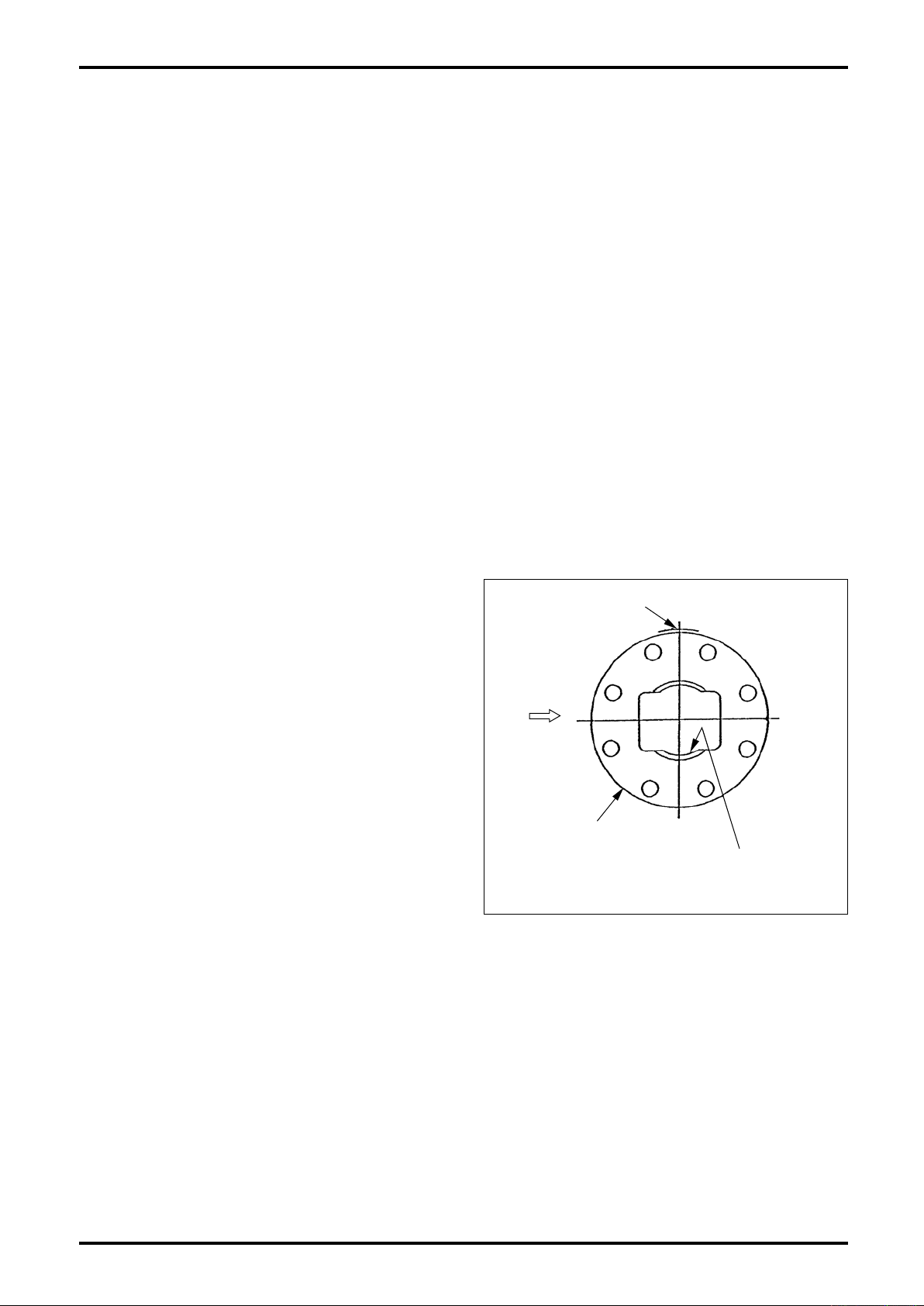
(1) Ins t al l t he h o ld -d o wn d i sc b e tw e en t h e
mounting nozzle (mounting flange) and gate
valve.
・Use extra care to install the hold-down disc
in the right physical orientation at this time.
Ensure that the arrow m a r k o n t h e side
of hold-down disc conforms to the actual
flow direction and that the arrow mark is on
the left hand side as viewed from the flow
direction (upstream side).
・Install a gasket on top and bottom of the
hold-down disc.
(2) Install the meter.
・Remove protective caps provided on the
sides.
・Ensure that the arrow mark on the cover
conforms to the flow direction.
・Ensure that the flanges of short pipe, gate valve and hold-down disc are flush and in line with the
periphery and the center mark (V-groove).
(3) With the gate valve fully open, insert the probe until the retaining ring comes into contact with the hold-
down disc by turning the handwheel. The guide should be at the match mark (V-groove) on the stud at
this time.
・Ensure that the vent valve is fully closed and that the fitting bolts are tight.
・In the event a leak persists through the gland packing, retighten the bolts holding the packing
retainer.
Hold-Down Disc
Arrow Mark
Flow
Directin
Tapered Face Up
Fig. 6.6
15
Page 16
D-582-3-E
Removal Procedure
(1) Disconnect wiring of the preamplifier.
(2) By turning the handwheel, retract the probe.
Retract it until the guide arrives at match mark "B" on the stud.
(3) Confirming that the probe has been retracted completely, fully shut off the gate valve.
(4) Taking precautions against internal pressure, carefully open the vent valve, allowing the internal
pressure to escape.
(5) Remove the flowmeter from above the gate valve.
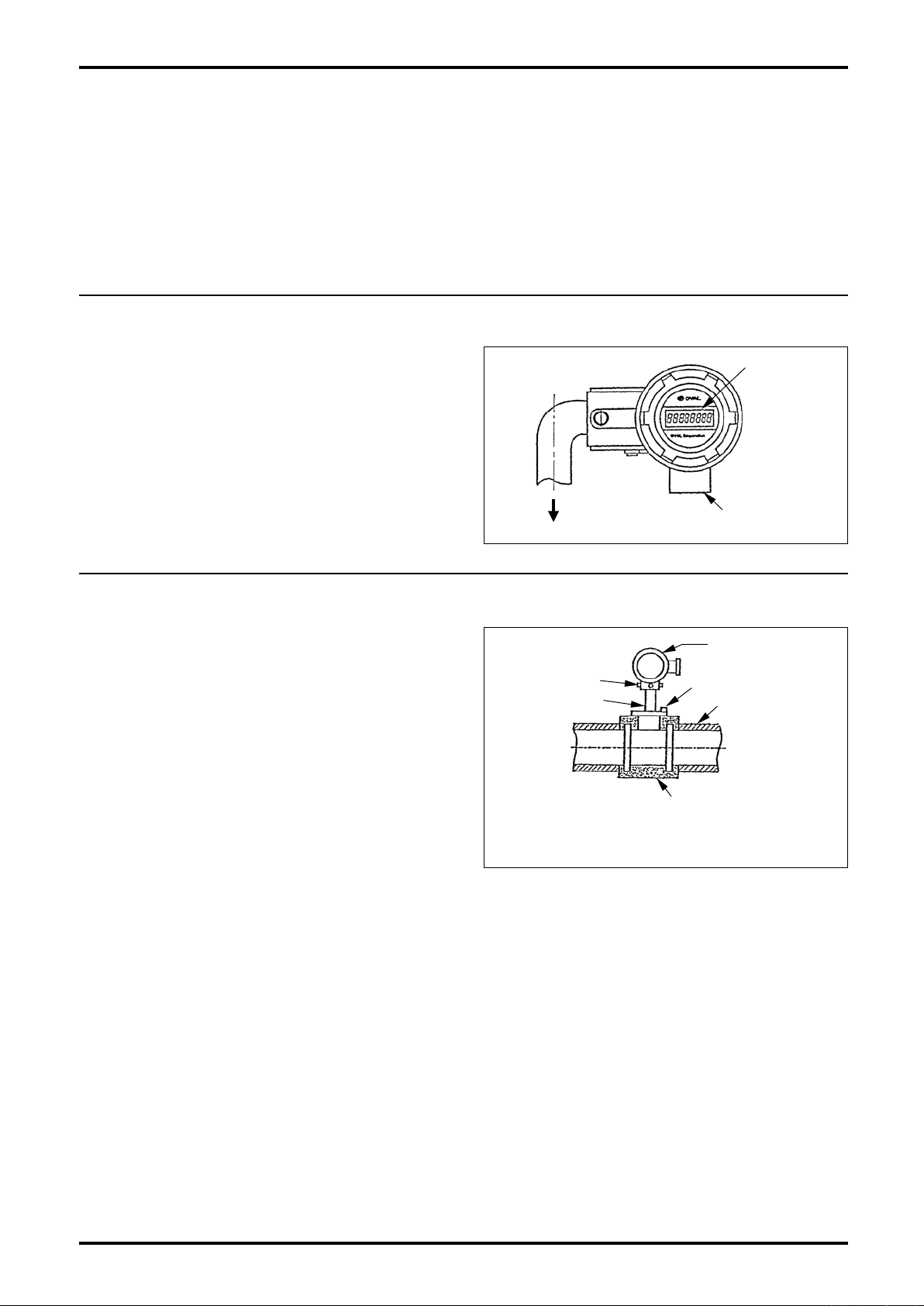
6.4.3 Preamplifier Orientation
As viewed from the direction of flow (upstream
side), the preamplifier typically installs inclined to
the left. The cable entrance points downward. In
the standard installation, the display of a display
equipp e d preamp l i fier ( PA25S) f a ces i n the
direction of outflow (downstream side).
Preamplifier
Display
6.5 Lagging Work
If heat insulation is considered for the piping,
simplified lagging (without mortar finish) is
suggested for the area where the meter is
installed to facilitate disassembly and inspection.
Such consideration will simplify meter connecting
bolt removal without the need of breaking the coat
of lagging material at servicing.
To Probe
Preamp Fitting
Screw
Adaptor
Lagging Work
Fig. 6.7
(Split-design desirable
Fig. 6.8
Cable Entry
Preamplifier
Flange Connecting
Bolt
Pipeline Lagging
Simple Lagging Work
for ease of maintenance)
16
Page 17
D-582-3-E
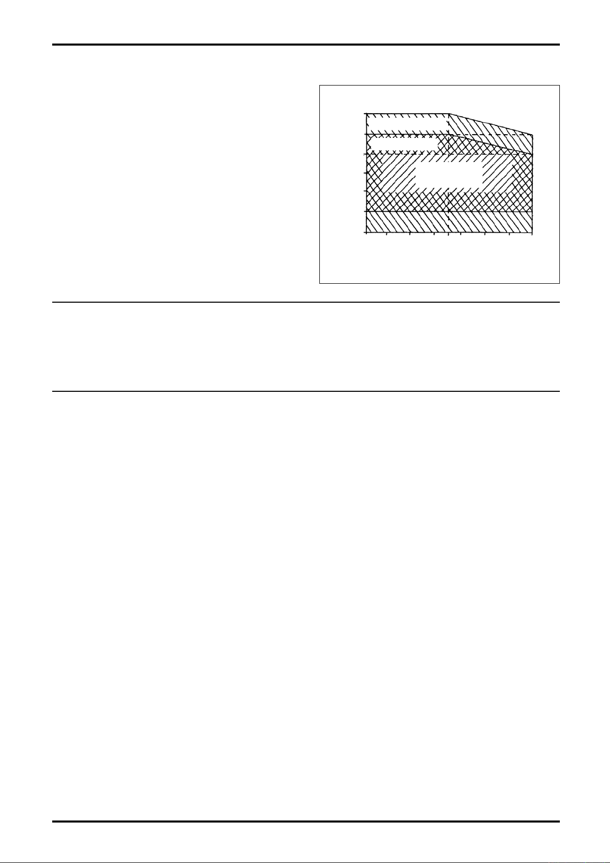
6.6 Ambient Temperature
Given in Fig. 6.9 is the allowable process fluid
temperature relative to the ambient temperature.
Ensure that the ambient temperature is held
within the rating.
If there is a possibility that the ambient
tem perature exc eeds the allo wable limit,
th e follow ing measures should be ta ken into
consideration.
● Avoid exposure to the direct rays of the sun.
● Separate from the piping and equipment of
elevated temperatures or provide a heat shield.
● Thermally insulate the preamplifier (in a low
temperature environment).
6.7 Partially Filled Pipe
When making measurement of a liquid, make sure the piping remains full of fluid and contains no trapped
air or gases. In applications where the existing piping conditions potentially cause a partially filled
pipeline, a purge valve should be provided.
80
Nonexplosionproof
60
Explosionproof
40
Operating
Range
150100500-30
125
Ambient Temp.(℃)
20
0
-20
-40
Fluid Temp.(℃)
Fig. 6.9 Ambient Temperature Range
300
250200
6.8 Working Stage and Hoist (hottap type)
To facilitate hottap type DELTA meter inspection and maintenance, we recommend that a working stage
and a hoisting device are provided.
17
Page 18
D-582-3-E
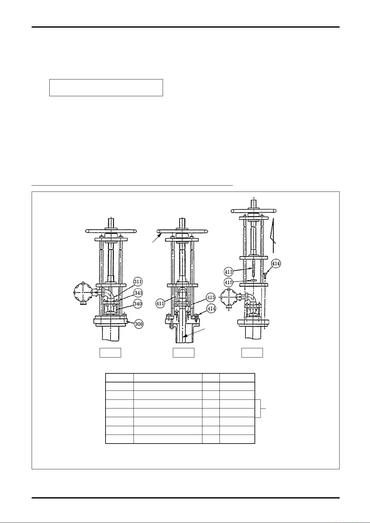
6.9 Hottap Type Drive Unit Removal
The drive unit (retractable assembly including the handwheel and screw axis) can be separated. It is
beneficial in applications where line vibration is great, or where a single drive unit is shared by multiple
flowmeters.
Drive unit removal procedure
① Installing the shaft fitting bolts [Fig. A]
Secure the adaptor A to the cover with shaft fitting bolts and hex nuts A. (This prevents the shaft from
being forced upward under line pressure.)
② Separating the shaft from its connection [Fig. B]
Taking off two hex nuts, turn the handwheel to extract the connecting studs from the adaptor A.
③ Removing the drive unit [Fig. C]
Taking off three hex bolts, remove the drive unit. Exercise care not to bump against the preamplifier or
other components.
Drive unit installation is the reverse of the removal instructions.
Handwheel
Screw Axis
Fig.A Fig.B Fig.C
No. Part Name Q'ty Remarks
309 Cover 1
311 Adaptor A 1
340
341 Hex Nut A 2 M12
411 Connecting Stud 2
414 Hex Bolt 3 M16
415 Hex Nut 2 M16
Shaft Retaining Bolt
2 M12
Retract
Option
18
Fig. 6.10
Page 19
6.10 How to Change Preamplifier Orientation
D-582-3-E
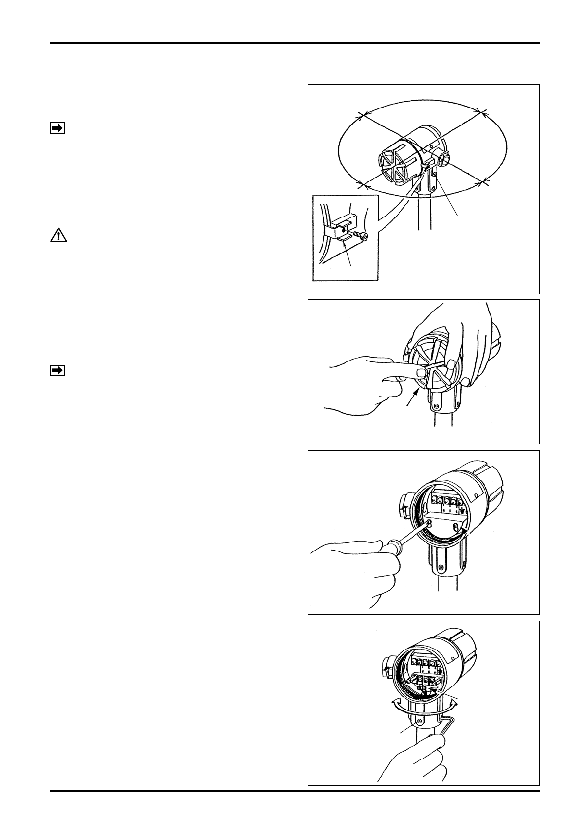
The preamplifier can be oriented to the desired
direction in 90°steps as shown in Fig. 6.11.
NOTE: To change the orientation, hex key (JIS
B 4648), nominal size 4, is required.
Th e preamplifier can be rot ated by
loosening its four hex socked head
screws, bu t b e sure to d isconnect
sensor lea d s before atte m p t i ng to
rotate it.
CAUTION: Turning the preamplifier with
se ns or l e a d s i n p l a c e m ay
damage the sensor.
Procedure
Refer to Section 15, "EXPLODED VIEW AND
PARTS LIST, FIXED TYPE" on pages 41 and 42.
① Turn off power.
② Remove the terminal box cover (Fig. 6.12).
NOTE: If the preamplifier is of explosionproof,
d i s e n g a g e th e la t c h (※) b e f o r e
removing the cover.
90°
Hex Socket Head
Screw
※
Latch
Fig. 6.11
Cover
③ Separate the shield strip (Fig. 6.13).
④ Disconnect sensor leads from the terminal
block.
⑤ Loosen a total of four hex socket head screws
securing the preamplifier's neck (Fig. 6.14).
⑥ Turn the preamplifier to the desired direction,
exercising care not to force the sensor leads.
⑦ When the preamplifier orientation has been
set, assemble in the reverse order of removal.
Fig. 6.12
Shield Strip
Fig. 6.13
Sensor Leads
Turn
Hex Soc. Head Screw
Fig. 6.14
19
Page 20
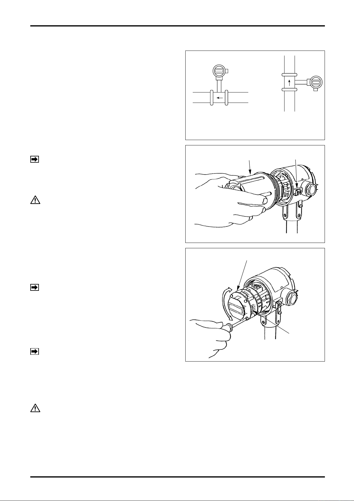
D-582-3-E
6.11 How to Change Indicator and Totalizer Orientation
If the preamplifier is equipped with local display
(indicator and totalizer), the display assembly can
be rotated to the desired direction in 90°steps
through 360°. By changing the angle of display
assembly (internal assembly), the indicator or
totalizer appears for maximum readability on a
vertical run or a horizontal run.
How to Change Display Angle
Refer to Sec. 14.4 "Display Installation" on page
40 and Sec. 15, "EXPLODED VIEW AND PARTS
LIST, FIXED TYPE" on pages 41 and 42.
NOTE: In explosionproof model, hex bar (JIS
B 4648), nom. size 3, is required to
take o ff t h e latc h and ch a n g e the
orientation.
WARNING:
① In the explosionproof model, remove the latch
securing the window cover (Fig. 6.16).
② Remove the window cover (Fig. 6.16).
③ L oos e n f our sc r ews ho l din g t h e d isp l ay
assembly and remove the display assembly
from its connector (Fig. 6.17).
NOTE:
In the case of externally powered
model, be sure to remove power
before you work.
The procedure above applies to the
separate-mount type preamplifier.
Horizontal Run Vertical Run
Fig. 6.15
Windowed Cover
Fig. 6.16
Display Assembly
Rotatable In 90°
Step
Latch
④ Orient the display assembly to the desired
angle, install it as far into the connector as it
will go and secure it with four screws (adjustable
in 90°steps).
NOTE: Make sure it is pushed in as far as it
will go.
⑤ Install the window cover in place.
⑥ The explosionproof model requires installing
the latch securely.
CAUTION: The cover must be screwed in
as far as it will go.
20
Connector
Fig. 6.17
Page 21
D-582-3-E
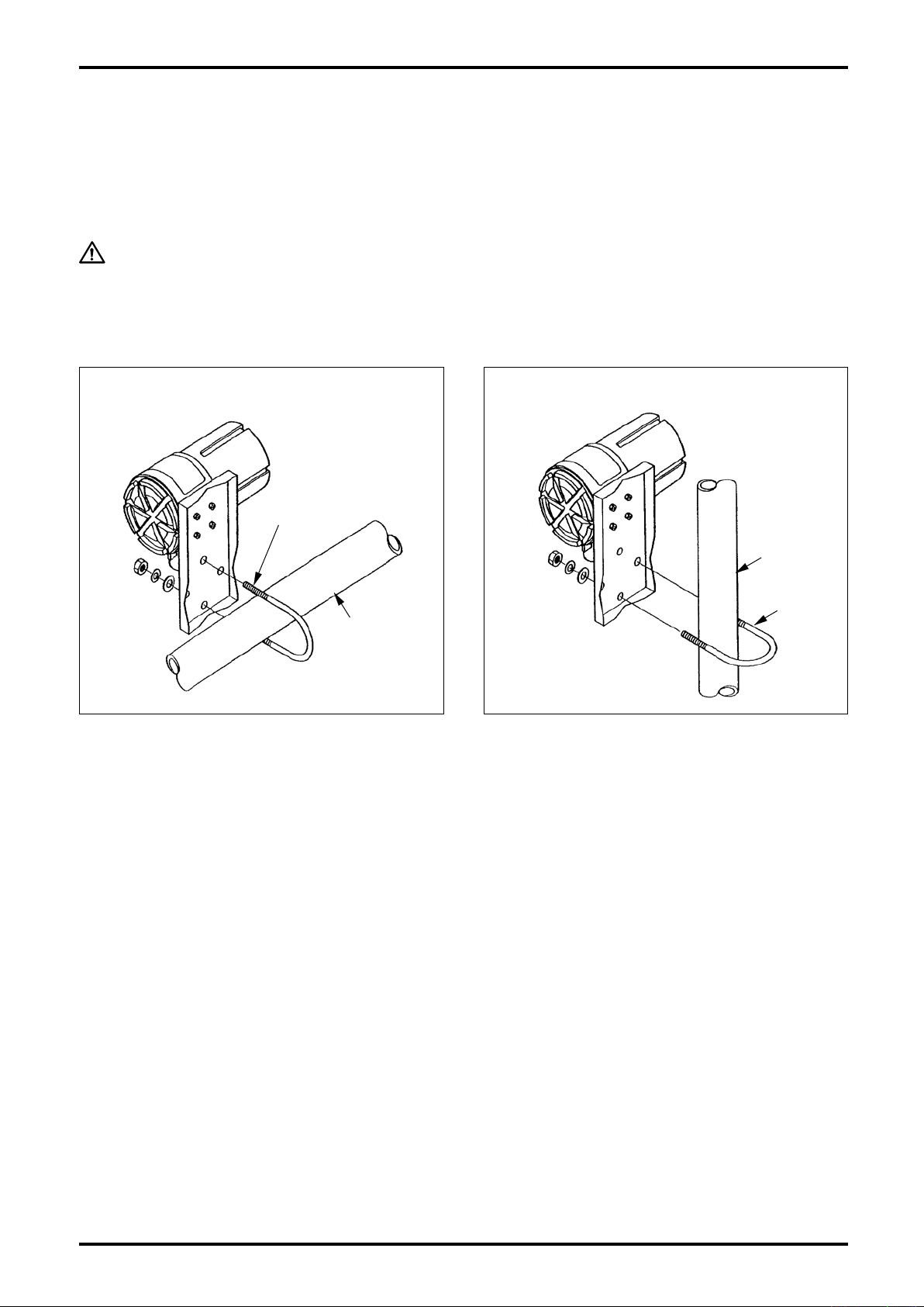
6.12 Separately-mounted Preamplifier Installation
① The maximum transmission length from the sensor is 200 meters; install the preamplifier within this
length.
② The preamplifier requires installation on a horizontal or vertical steel pipe 2 inches in diameter with
furnished U-bolt.
③ Select an installation location easy for maintenance and in a desirable environment.
CAUTION
Locations that comes under any of the following conditions should be avoided:
① Difficult for inspection and maintenance.
② Temperature change and/or vibration is excessive.
③ Possible immersion in water.
Installation on a Horizontal Pipe Installation on a Vertical Pipe
Preamplifier
U-Bolt
2″Steel Pipe
Fig. 6.18
Preamplifier
Fig. 6.19
2″Steel Pipe
U-Bolt
21
Page 22
D-582-3-E
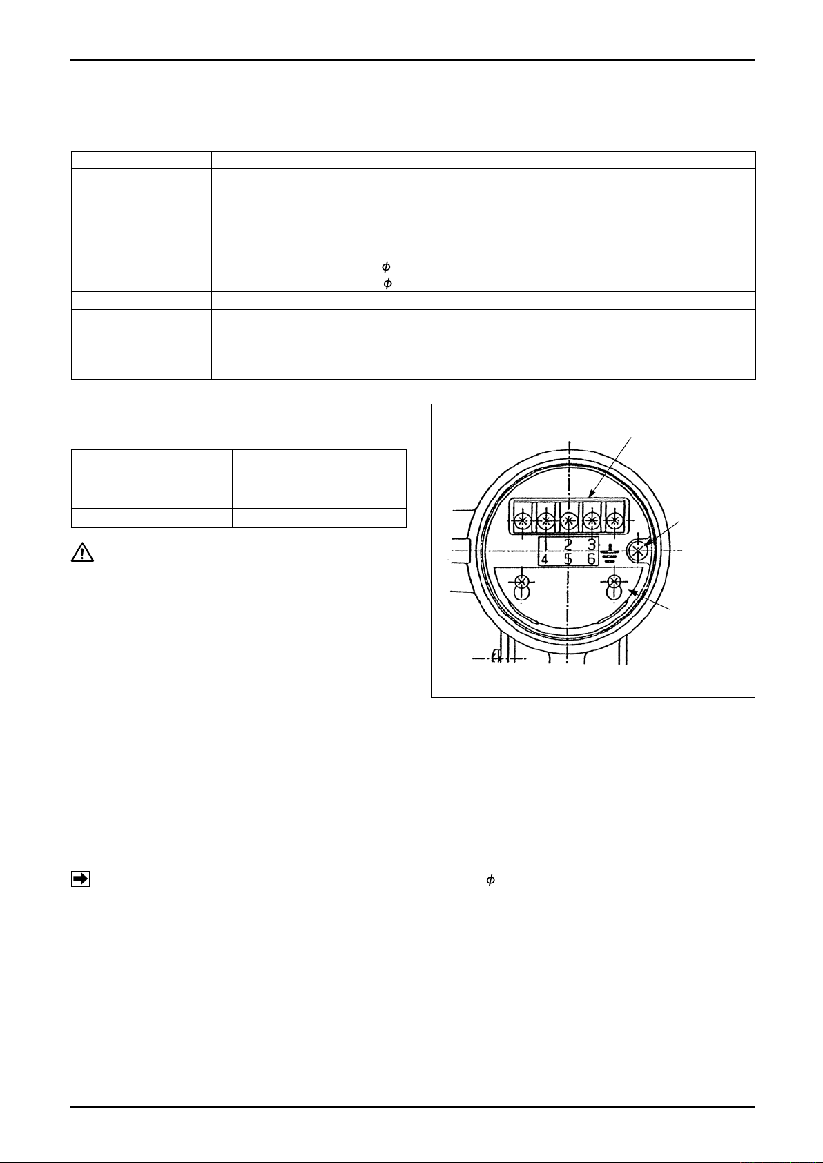
7. WIRING CONNECTIONS
7.1 Wiring Specifications
Wiring Entry G1/2 (PF1/2) internal thread
Transmission Length
Cables Used
Terminal Block
Explosionproof Work
7.2 Terminal Connections
Output Specification
Both analog type and
pulse output type
Open collector pulse output type
CAUTION
Cable shield must be grounded to the earth
ground terminal in the terminal box.
Wire external cable in a way that it is not put
under the shielding plate.
Preamplifier to receiving instrument: 1 kilometer max.
Probe to preamplifier: 200 meters max. (separately-mounted model)
Probe to preamp: 3-conductor shielded cable 1.25mm2 min. (separate mtg. type)
Preamplifier to receiving instrument: 2-conductor shielded cable 1.25mm2 min. (analog, current pulse type)
3-conductor shielded cable 1.25mm2 min. (open collector pulse type)
Finished outside diameter: 13.5mm max., nonexplosionproof model
8.5 to 11mm, flameproof model
Cross recess pan head screws, M3.5
Complies with the Recommended Practice for Explosion-Protected Electrical
Installations in General Industries
l
Earth ground the preamplifier.
l
Be sure to use pressuretight gasketed lead-in specified.
Table 7.2 Terminal
Terminal No.
① :+
② :-
①:SUP ②:COM ③:SIG
Table 7.1
Terminal Block
Ground
Terminal
Shield Strip
Fig. 7.1 Terminal Block for Exlernal Connections
7.3 Considerations on Wiring Connections
⑴ If the meter is of explosionproof configuration, the following pressuretight gasketed lead-in should be
used. (Explosionproof rated models are furnished with it)
Certified explosionproof products
Part Name: Flameproof gasketed union
Model: KXY-16
Manufacturer: Kokusan Hambai Co., Ltd.
NOTE: The lead-in above is furnished with rubber gaskets 9, 10, and 11mm in ID. Select one that
best suits the O.D. of the cable used.
⑵ Terminal screws on the terminal block are of M3.5. Use applicable crimp-style terminals.
⑶ The ground terminal of the preamplifier must be earth grounded.
⑷ Pitch down the cable at the wiring entry to prevent rainwater and moisture from getting into the
equipment.
⑸ To eliminate the possibility of stray current pickup, route field wiring sufficiently away from high tension
lines, power lines and power equipment.
⑹ In a region where lightning is expected, a lightning arrestor should be provided.
⑺ In case of TIIS explosionproof type used under the ambient temperature of 50℃ or higher, use a cable
resistant to the temperature of 70℃ or higher.
⑻ Wire external cable in a way that it is not put under the shielding plate.
22
Page 23
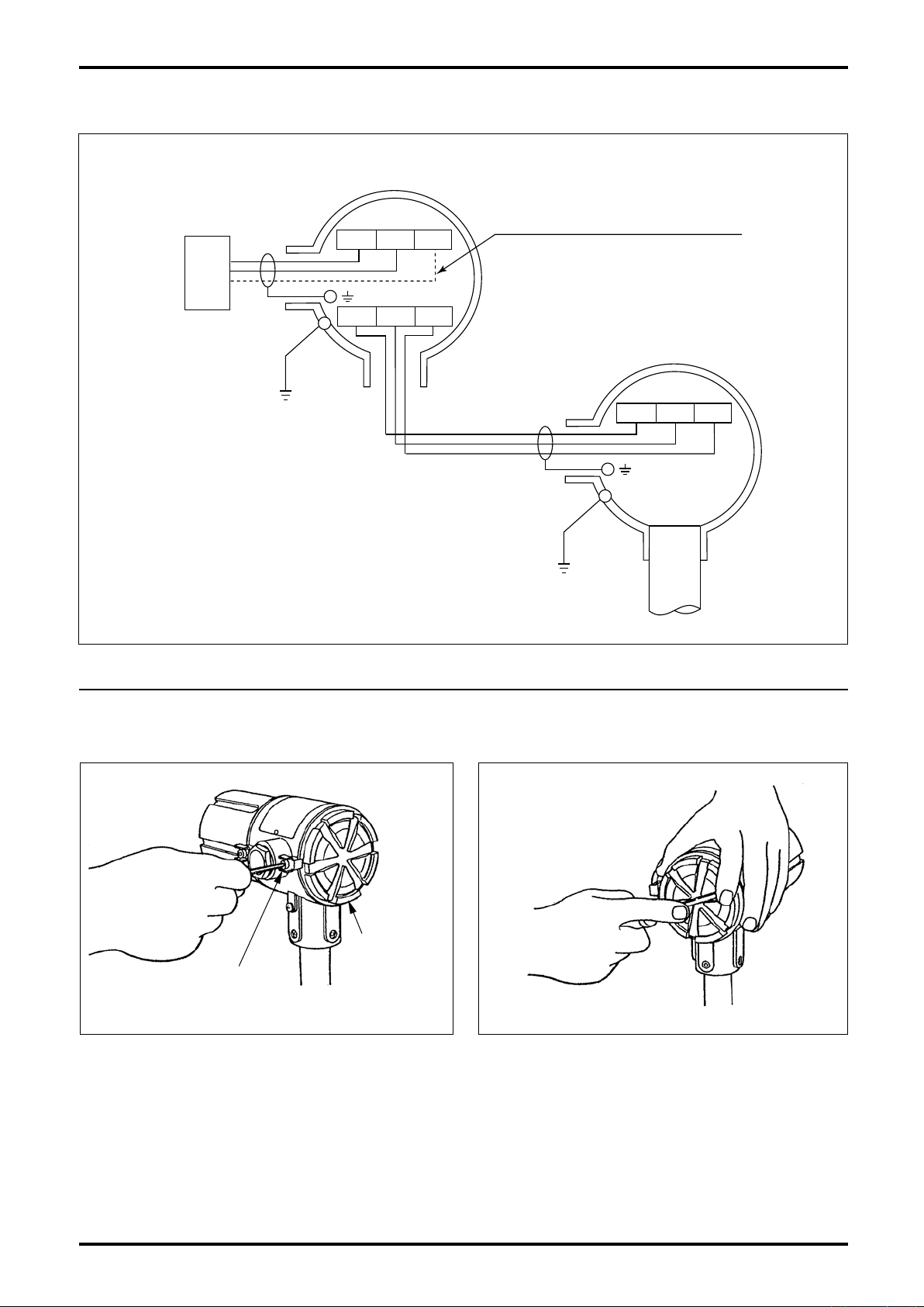
7.4 Separate-mount Preamp to Sensor Terminal Box Wiring Connections
4
5
6
1
2
3
1
2
3
Fortheopencollectorpulseoutput,
alsoconnectawiretoterminal3.
TerminalBoxtoPreamplifier
TerminalBoxtoSensor
ReceivingInstrument
GND
GND
D-582-3-E
7.5 Terminal Box Cover Removal
⑴ The illustration above shows the terminal box
cover to be removed.
Lock
Fig. 7.3 Fig. 7.4
Terminal Box
Cover
Fig. 7.2
⑵ Apply the key to the terminal box cover and turn
it as shown until it comes off. The terminal block
is now accessible.
23
Page 24
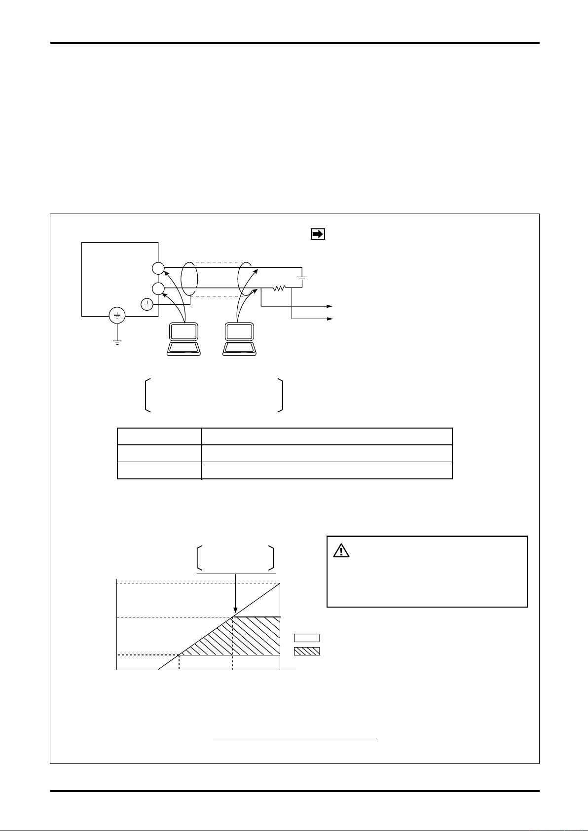
D-582-3-E
SupplyVoltageE(VDC)
RL(loadResistance)
1571Ω
1000Ω
250Ω
12V0
17.25V
33V 45V
7.6 Hookup with Receiving Instruments
The 2-wire signal transmission system used in this flowmeter furnishes DC power to the meter. It serves
as the power lines and signal lines as well with pulse or analog current output.
An OVAL receiving instrument can be coupled directly, but instruments in general which are designed to
accept a voltage signal input require a load resistor connected in series for voltage conversion. Since the
voltage signal level varies with the load resistance value, determine the load resistance value by referring
to the receiving instrument specifications and the acceptable load resistance range shown below.
Communications with a PC (OVAL Smart Communication Unit EL2310) requires a 250 to 1000Ω Ioad.
l In case a voltage input is fed to the receiving instrument
NOTE: See page 22 for terminal identification.
+
Flowmeter
Preamplifier
1
-
2
RL
+
DC Power Source
-
+
Voltage Signal
-
(To Receiving Instrument)
GND
PC PC
Personal Computers
EL2310
Smart Communication Unit
Output Voltage Signal (V)
Pulse Output ON / OFF (20mA × RL) / (4mA × RL)
Analog Output (4mA × RL) - (20mA × RL)at 0 ~ FS
E-12V
RL = -------
21mA
CAUTION
If OVAL Smart Communication Unit
EL2310 is to be connected, use it
below 33 VDC in power supply voltage.
24
Area: Acceptable range for operation
Area: Communicable range
Example: If supply voltage is 24VDC with load re-
sistance 250 Ω in the hook-up above, then
a 1 to 5V DC voltage output is obtained.
Acceptable Load Resistance Range
Fig. 7.5
Page 25
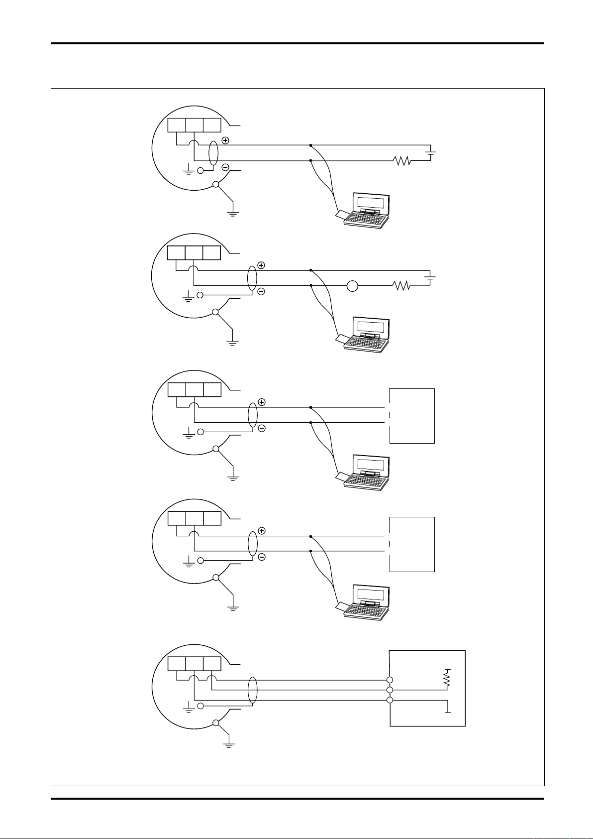
7.7 Wiring Diagrams (examples)
4/20mADC current pulse
Power
Power
Load Resistor
SIG
4/20mADC current pulse
GND
GND
GND
GND
GND
1 2 3
1 2 3
1 2 3
4to20mADC
4to20mADC
RL
RL
A
Load Resistor
EL4061
EL4101
Receiving Instrument
+24VDC
SIG
0V
1 2 3
EL2310
PC
EL2310
PC
EL2310
PC
EL2310
PC
①
②
②
③
COM.
SIG.
SUP.
1 2 3
12 to 45VDC
Max.
30VDC
←
Max.50mA
Analog Output
D-582-3-E
Pulse Output
Open Collector
Pulse Output
Fig. 7.6
25
Page 26
D-582-3-E
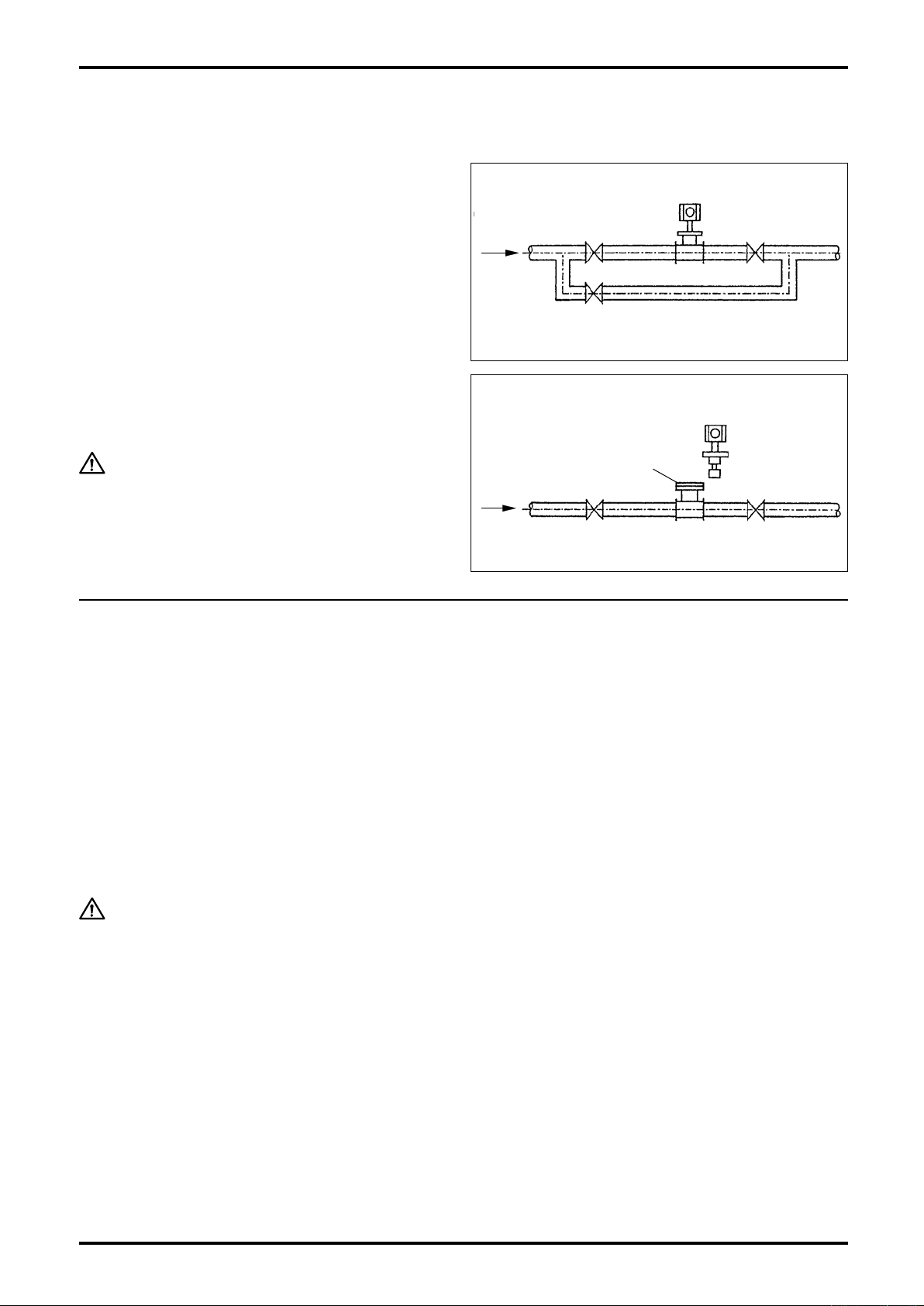
8. OPERATION
8.1 Flushing the Piping Assembly
(1) On a newly installed piping assembly where
scale, sludge and other foreign matter are
expected, follow the instructions given below,
using a bypass line (Fig. 8.1).
(2) If there is no bypass line, install a short pipe
sect i on i n pl a c e o f the flo w m ete r bef o r e
flushing the piping assembly (Fig. 8.2).
(3) Flushing Instructions
① Use clean water.
② Flu shing water v elocity sho u ld be high
enough - preferably from 4 to 6 meters/sec.
③ Perform flushing for extended periods of
time.
DELTA Meter
Flow
Direction
Bypass Line
Fig. 8.1
DELTA Meter
CAUTION:
To avo id damag e t o the flowmeter, conduct flushing before
meter installation, or, in the case
of hottap type, with the probe
retracted.
Flow
Direction
Blind Flange
Fig. 8.2
8.2 Operation Procedure
① Drainage (in steam service)
To prevent steam hammer, drain the piping assembly completely.
② Checking the meter for proper installation.
To ensure safety, inspect connecting bolt, gaskets, etc. for tightness and other condition.
Make sure of the flow direction also.
③ Leak check
Fill the meter with fluid and check for any leak.
④ Upon completion of wiring connections, turn on power.
Verify that the receiving instrument will not register erratic counts with no flow.
⑤ Starting up the measurement line
By starting up the pump or opening up the valve, carefully allow the fluid to flow.
CAUTION: To safeguard the equipment connected, exercise care not to increase the flowrate
sharply.
⑥ Checking the operation
Verify that the receiving instrument registers properly.
Make sure that the fluid conditions (pressure, temperature, etc.) and flowrate conform to the meter
specifications.
26
Page 27
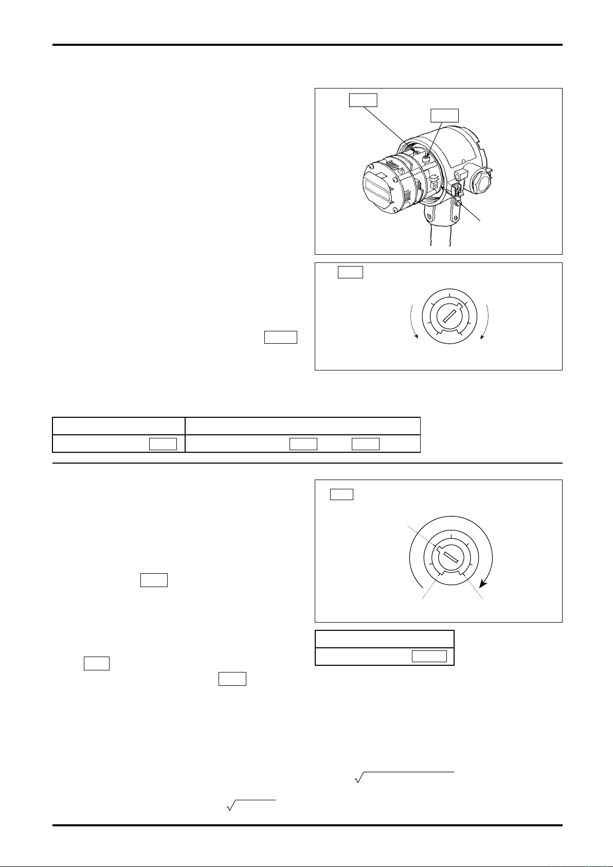
Gain Down
Gain Up
AMP
Potentiometer
AMP
TLV Potentiometer
Potentiometer
Amplifier Board
TLV
Adjustabl
Range
350mVp-p
80mVp-p
160mVp-p
(Factory Set)
Potentiometer
Amplifier Board A
9. FLOW SENSITIVITY ADJUSTMENT PROCEDURE
Flow sensitivity is accurately adjusted over the
specified flow range before the meter leaves the
factory.
If no output appears at the minimum flowrate
pre s uma b ly d ue to y our sp e cif i c o p era t ing
conditions (disturbance from external interference,
for example), readjust the sensitivity (trigger
level).
The same sensitivity readjustment is also required
in cases where the receiving instrument registers
erratic counts at meter shutoff due to noises
caused by pipeline oscillation, etc. after sensor replacement.
9.1 Amplifier Gain
Amplifier gain (amplification) is adjusted to the
sensor used. Do not attempt to readjust it except
when the sensor has been replaced.
A m p l i f i e r g a i n i s a d j u s t a b l e w i t h A M P
potentiometer on the amplifier board A. Monitor
the vortex waveform following amplification on the
oscilloscope and adjust such that the peak value
of vortex waveform is 100mV p-p approx. at the
minimum flowrate.
D-582-3-E
Fig. 9.1
Fig. 9.2
9.2 Trigger Level
Tr i gge r lev e l (p u lse g ener a tion sens i tivi t y)
determines the peak value of amplified vortex
signal above which signal-to-pulse conversion
takes place.
It follows that trigger level adjustment allows flow
sensitivity adjustment.
With increasing TLV pot position (clockwise
ro t a t io n) , f lo w s e n si ti v i t y de cr e a s es ; wi t h
de cr ea si ng i t (c o u n t e r c l o c k w i s e ro t a t i o n )
increases flow sensitivity.
If me a s uremen t is m a d e nea r the m i nimum
flowrate and resultant signal output is too small,
adjust TLV pot to a smaller position. An important
precaution to remember: setting TLV pot to an extremely small position can lead to failure of pulse
generation due to noises caused by pipeline oscillation or other external disturbances.
① By increasing the trigger level, the flowrate sensitivity decreases with the ratio of trigger level (sensitivity
② When sensitivity is changed, the resultant minimum flowrate (measurable lower bound flowrate) is
Sensitivity Potentiometer Vortex Waveform After Amplification
Amplifier Board A: AMP Amplifier Board A: VTX (+)to OV (-)
Fig. 9.3
Trigger Level Potentiometer
Amplifier Board A:
TLV
ratio).
Example: When a trigger level 160mVp-p is changed to 350mVp-p, the resultant sensitivity will be
160/350≒1/2.2 (sensitivity ratio) times.
approximately the standard minimum flowrate multiplied by 1/(Sensitivity ratio).
Example: When a trigger level 160mVp-p is changed to 350mVp-p, the resultant minimum flowrate
will be approximately 350/160 ≒ 1.48 times the minimum flowrate.
27
Page 28

D-582-3-E
10. PARAMETER SETUP
Specifications of individual flowmeters are configured by establishing the following parameters.
Parameter are set through communications using a PC and OVAL Smart Communication Unit (Mode
EL2310). (See the section under the topic "Wiring Connection." )
Since parameters are correctly established before the meter is delivered to the customer, no further
configuration is normally required.
For p rocedure s to review a nd set up para meters, see t he instruc tion manua l for OVAL Smart
Communication Unit EL2310.
● Description of Parameters
Parameter Setup Range or Item to be Selected Units of Measure
Tag No. Enter alphanumerics up to 8 characters.
Sensor Serial No. Enter numerals up to 7 characters.
Sensor type
Date of manufacture Numerals (the year represented by 2-digits)
Sensor material Select one from SUS316, Hastelloy C, Monel, Tantalum,
Flange ratings Select one from JIS 10K, JIS 20K, JIS 30K, ASME 150,
Description Alphanumeric: accepts 15 characters max.
Message Alphanumeric: accepts 32 characters max.
Preamplifier display
Instantaneous flowrate
units
Measurement units of
totalized flow and factored
pulse output
Temperature units One selected from ℃,°F , or K
Pressure units Select one from Pa, kPa, MPa, mmHg, psi, bar, atm, or Torr.
Meter factor
(value at 20℃ )
Linear expansion
coefficient (α)
Linear expansion
coefficient (β)
Set the flowmeter type conforming to the flowmeter model code.
Enter alphanumerics up to 8 characters.※
Special, or Unknown.
ASME 300, ASME 600, Special, or Unknown.
Generally used for entering brief comments.
Setup of the type of totalizer display in the flowmeter preamplifier.
Select one from
・Total flow
・Instantaneous flowrate
・% instantaneous flowrate
・% bar graph
①L/min,L/h,m3/min,m3/h,kL/min,kL/h
②L/min[normal],L/h[normal],
m3/min[normal],m3/h[normal]
③g/min,g/h,kg/min,kg/h,t/min,t/h
④ton(US)/min,ton(US)/h
Select one from the available units having the same unit as
the attribute number in the "Totalized flow and factored pulse
units" setup.
①L,m3,kL
②L[normal],m3[normal]
③g,kg,t
④ton(US)
Select one from the available units having the same unit as the
attribute number in the "Instantaneous flowrate units" setup.
(Each unit shows gauge pressure except for mmHg, atm and Torr.)
Within±50% of nominal meter factor L/P
0≦"Linear expansion coeff (α)"≦0.00003
Default setting: 0.000016
0≦"Linear expansion coeff (β)≦0.00003
Default setting: 0.000016
28
Cont'd
Page 29

Parameter Setup Range or Item to be Selected Units of Measure
Metered fluids
Calculation
Reference temperature
for correction
Reference temp.
Select one from ・Gas and steam
・Liquid
Select one from・Calculation on actual flow
・Calculation corrected for temperature
and pressure
・Saturated steam calculation
・Superheated steam calculation
・With "Calculation on actual flow" or "Calculation corrected
for temperature and pressure at "Calculation,"
-250≦"Reference temperature for correction"≦450[℃ ]
・With "Saturated steam calculation" or "Superheated steam
calculation" at "Calculation,"
100≦"Reference temperature for correction≦450[℃ ]
NOTE: By the "Temperature units" setup, convert the
temperature range above.
Same as "Reference temperature for correction". by "Temperature units"
for measurement
(process temp.)
Reference pressure
for correction
Reference pressure
-0.0098≦"Reference pressure for correction"≦10.8[MPa]
NOTE: Relative to the pressure unit setup, convert the
pressure range above.
Same as "Reference pressure for correction". by "Pressure units"
for measurement
(process pressure)
Fixed conversion
value
Zero flowrate
Span flowrate
(Full scale flowrate)
Low cutoff flowrate
High alarm flowrate
Weight of totalized flow
and factored pulse output
Pulse width
(factored pulse)
Pulse output type
Damping (analog,
0.0001≦"Fixed conversion value"≦99999999
When the mass flowrate units are selected with "Calculation
on actual flow" or "Calculation corrected for temperature and
pressure" at "Calculation", set the density (fixed value).
Deviation factor is set up, in practice, by setting[1/deviation
factor].
Always set to 0. by "Instantaneous
Min. flowrate×3≦"Span flowrater"≦Max. flowrate×1.5
(See "General Specifications" for the max. and min. flowrates.)
Set up such that 0<"Low cutoff flowrate <"Span flowrate"
or "High alarm flowrate".
"High alarm flowrate" > 0
where "High alarm flowrate" > "Low cutoff flowrate"
0.01≦"Pulse weight"≦10000
(See "General Specifications".)
10≦"Pulse width"≦1000
where pulse width duty at full scale must be below 50%.
Select one from ・Factored
・Unfactored
0≦"Damping"≦100
instantaneous rate)
※ "Sensor type (flowmeter type)" is represented by the following:
Default setting: 50
Default setting: 2.5
D-582-3-E
by "Temperature units"
by "Pressure units"
Calculation on actual
flow in kg/m3[normal];
"Calculation corrected
for temperature and
pressure" in kg/m3[normal]
flowrate units"
by "Instantaneous
flowrate units"
by "Instantaneous
flowrate units"
by "Instantaneous
flowrate units"
by "Totalized flow and
factored pulse units"
ms
s
V ※ ※ □ □ □ □ □ (8-digit code)
Output ・Analog type: A
・Pulse type: P
Fluid ・Gas, steam: G
・Liquid: L
Sensor nominal dia. is set in 3 digits.
Example: If sensor nominal dia. is 500mm, set to 050.
The first 1 to 3 digits in the sensor model code is set.
Examples: VXS
29
Page 30
D-582-3-E
Example of Display
Mode Symbol
Totalized flow
Instantaneous
flowrate
% Instantaneous
flowrate
8-segment
% bar graph
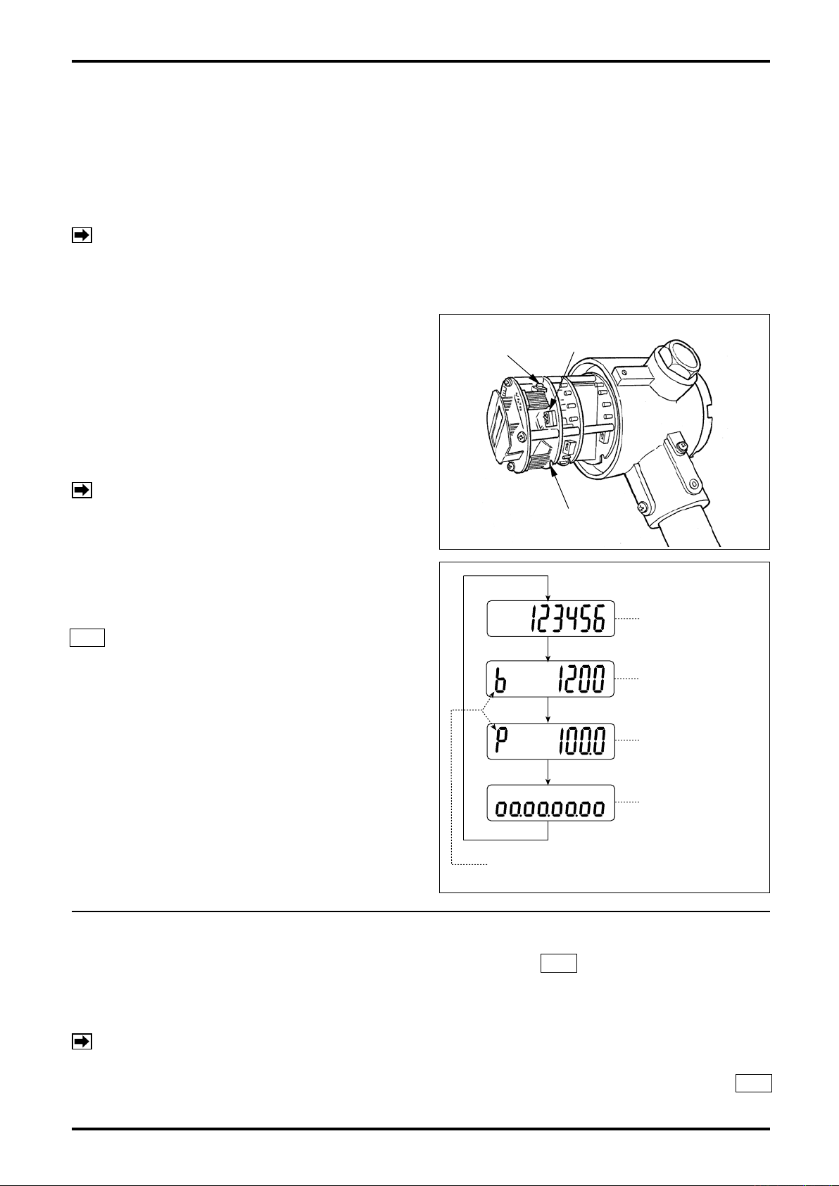
11. BUILT-IN DISPLAY FUNCTIONS AND OPERATION
(Totalizer or indicator equipped model)
Description of Display Functions
This totalizer can display a total of four different readings: total flow, actual instantaneous flowrate,
percent instantaneous flowrate, and 8-division % bar graph. It also shows the following error messages:
Full scale is exceeded: ErrorFS
Upper-end flowrate is exceeded: ErrorOF
NOTE: When both errors above have occurred, message "ErrorOF" has priority over the other.
11.1 Display Selection
Display is selectable either with the display select
switch located inside the preamplifier or through
communications using the Smart Communication
Unit.
If c ommunicati ons is your cho i ce, follow t he
instructions outlined in the Smart Communication
Unit EL2310 instruction manual.
NOTE: Select your option at "Preamplifier
Information" menu at "Setup" on the
PC screen.
(totalizer equipped model)
SW1
[MODE]
CPU Board
SW2
[PROTECT]
Fig. 11.1
With display select switch
Opening up the cover facing the internal assembly
of the preamplifier, press the display select switch
SW1 located on the isolation board. The display
will then scroll forward each time this switch is
pressed as shown in Fig. 11.2.
Fig. 11.2
11.2 Total Flow Reset
Displayed total flow can be reset either by the display select switch SW1 or through communications
with Smart Communication Unit. If communication is your option, see the instruction manual for Smart
Communication Unit EL2310.
NOTE : Select your option at "Measurement" at "Display" menu on the PC screen.
30
With Display Select Switch (totalizer equipped model)
While the totalizer is in the total flow display mode, holding the display select switch SW1
depressed for more than 3 seconds resets the total flow.
Page 31
D-582-3-E
②
①
Totalizer Equipped
15 seconds after power on.
(Com Standby Mode)
Communication is started
within 15 seconds after
power on.(Com Mode)
12. PRECAUTIONS IN PULSE OUTPUT TYPE
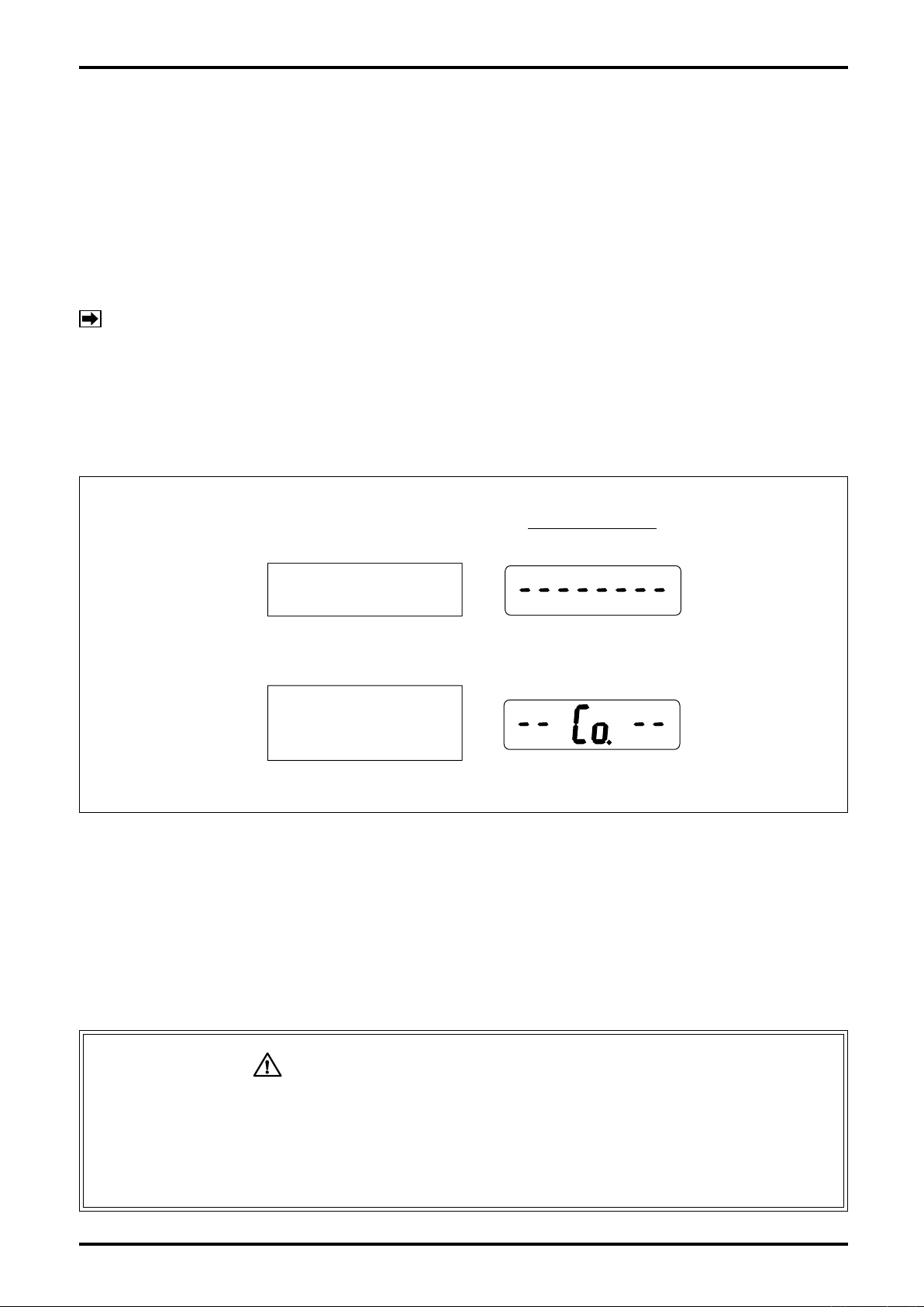
(1) If your model is of pulse output type, the pulse output and total counter remain inoperative for 15
seconds approx. after power on and while communications with Smart Communication Unit continue.
For 15 seconds approx. after termination of communications, the pulse output and total counter also
remain inoperative.
(2) Requirements for validating communications
Communication is valid only when the following requirements are met:
◇ Flowrate at zero (There is no pulse output.)
◇ Within 15 seconds after power turn-on
NOTE: The period of 15 seconds immediately after power on is called "Communication standby
mode." (The built-in indicator, if so equipped, will display as shown in ① in the figure below.)
If communications are started during this time period, a switchover to "Communication mode"
takes place, permitting you to communicate until power is turned off the next time. (The builtin indicator will display as shown in ② in the figure below.) To start flow measurement routine,
turn power off and on again. (After power cycling, the pulse output and total counter will also
remain inoperative for 15 seconds.)
(3) While communications continue, the receiving instrument (total counter, etc.) may overcount under
certain circumstances. To eliminate the possibility of such erratic extra counting, precautions should be
taken by either disconnecting the receiving instrument before starting communications, or putting on
paper the current total reading and other important data.
(4) Except for the purpose of communications, d o n o t a t t e m p t t o c o n n e ct t he p robe of S mart
Communication Unit with the signal lines. If its probe is left connected, the influence of capacitive
impedance the interface has could go to the point of producing distorted signal waveforms and, as a
result, the receiving instrument would fail to receive pulse signals accurately.
The analog type generally permits communications with Smart Communication Unit.
However, if, in an attempt to alter current parameters, the meter is configured by mistake
such that the new parameters are incompatible with the specification, resultant sharp
changes in output may disturb the behavior of the receiving instrument. It is good practice,
therefore, to make parameter changes while the fluid flow is at zero.
Fig. 12.1 Display at Power ON of Output Type
PRECAUTION FOR ANALOG OUTPUT TYPE
31
Page 32
D-582-3-E
IN
TP−
Receiving
Instrument
(Power)
mA Meter
(for analog type)
Isolation Board
Preamplifier(Open collector output)
Pulse Generator
IN TP−
SIG. 0V
OUTPUT
+
−
Isolation
Board
Receiving
Instrument
(Power)
mA Meter
(for analog type)
Pulse Checker
(PC-2201)
13. PREAMPLIFIER OPERATION CHECK WITH SIMULATED PULSE INPUT
(Output and display)
At zero flow, you can check the preamplifier operation for its output and display according to the
procedures as set forth below.
CAUTION: Operation check should be conducted with zero flow.
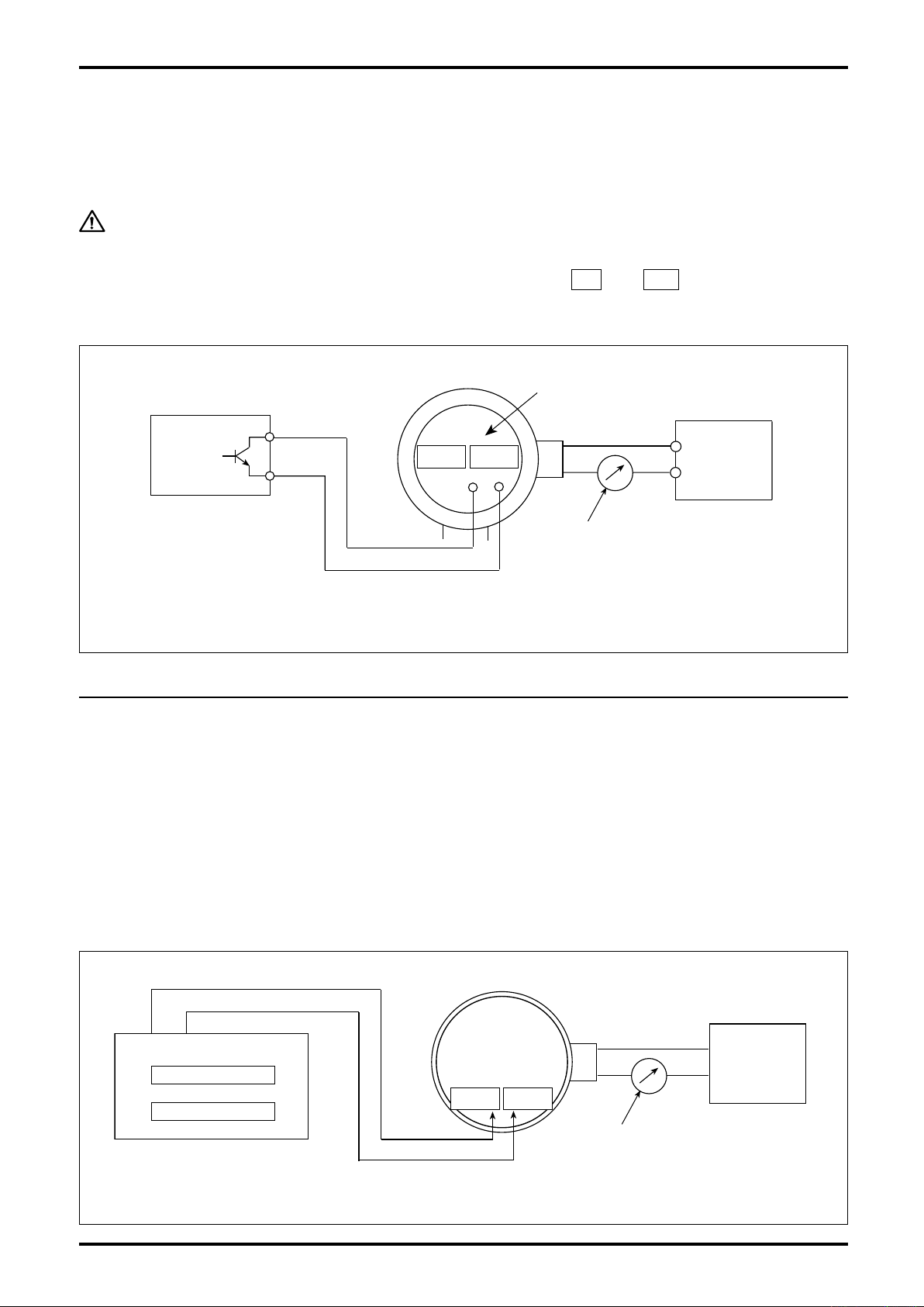
13.1 Test Setup
Couple the pulse generator (open collector output) across test pins IN and TP- on the isolation board.
Feeding a full-scale frequency pulse train from the pulse generator causes the preamplifier to produce a
100% output.
Fig. 13.1
■ Pulse Generator
Illustrated diagrammatically is the test setup if OVAL pulse checker (Model PC2201 is available as a pulse
generating source).
(Also refer to the pulse generator instruction manual.)
Pulse Checker Switch Settings
・ OUTPUT → O. C
・ WIDTH → 0.25
・ SETTER → 100%
・ RATING → 1 to 10K (chosen according to the frequency established)
・ FREQUENCY → Frequency established
32
Fig. 13.2
Page 33

D-582-3-E
13.2 Full Scale Frequency Calculation
The full scale frequency of unfactored pulse equivalent to the full scale flowrate is calculated by the
following formula:
Full scale frequency (Hz) =
NOTE: Full scale flowrate must have the same unit of measure as meter factor. The full scale
frequency established before shipment from the factory is stated in the ANALOG F.S. on the
nameplate.
If the fluid temperature ("Reference temperature for measurement" setting) is below 10℃ or above +60 ℃,
multiply the meter factor with a temperature correction factor determined by the following equation:
Temperature correction factor= (2α+β)×(Fluid temperature [℃ ] - 20) +1
where
α: Expansion coefficient of the meter material (Standard: 0.000016)
β: Expansion coefficient of the meter bluff body material (Standard: 0.000016)
Process temperature: Setpoint in the "Reference temperature for measurement" (units in terms of ℃ )
Example: Given the meter factor Mf = 0.06021 L/P and
Full scale = 200m3/h, find the full scale frequency.
Full scale frequency =
= 922.7 Hz
Full Scale Flowrate (volume unit/hour)
Meter Factor (volume unit/P) 3600
200m3/h
0.06021(L/P) 3600
×
1000
×
1
If the flowmeter produces an output representing the normal fixed conversion of gases or the mass fixed
conversion of steam, perform conversion into a reduced meter factor by multiplying the meter factor in
volumetric term (L/P) with normal conversion factor or density and, from the meter factor thus obtained,
calculate the full scale frequency.
Example: Given meter factor Mf = 0.06021 L/P
Fluid density ρ = 1.638 kg/m3 (g/L)
If the full scale is 400 kg/h, we obtain the reduced meter factor Mf'
Mf' = 0.06021 (L/P)×1.638(g/L)
= 0.09862 (g/P)
It follows that
Full scale frequency =
= 1126.7 Hz
400kg/h
0.09862(g/h) 3600
×
1000
33
Page 34

D-582-3-E
14. MAINTENANCE
As long as your DELTA meter is placed in service under proper operating conditions, it will perform
satisfactorily over extended periods of time. But scale, sludge and other foreign matter contained in the
metered fluid could adhere to the inner walls of your meter and degrade meter performance in time. For
this reason, periodic disassembly and inspection is suggested.
14.1 Disassembly and Inspection
◇ Time for disassembly and inspection◇
(1) Six months after the first time operation.
(2) According to the conditions observed in (1) above, determine the second time disassembly and
inspection. (Once a year is suggested under normally encountered operating conditions.)
◇ Inspection points◇
(1) Probe (probe body and bluff body) for deposits.
(2) Observe the output waveform from the amplifier board in the amplifier and make sure that it conforms
to the waveform shown in the section under the topic "TROUBLESHOOTING" in the preamplifier
instruction manual.
14.2 Disassembly and Inspection
(1) Probe Inspection
Taking off hex bolt (107) and three hex socket head setscrews (109A), the probe body (101) can be
separated. Inspect probe body (101) on its inner walls and bluff body (105) for condition and clean.
Foreign matter in the capillary slots (a total of four places) on the sides of bluff body in particular must be
removed thoroughly. Adhere to the following instructions during this procedure:
(2) Sensor Removal
If it is desired to remove the sensor for sensor replacement or other reason, proceed as follows:
① Firstly separate the preamplifier in the following manner:
(a) Remove power.
(b) Remove cover (310) on the terminal box. (→see page 23).
(→see page 23).
(c) Disconnect the cable of external wiring. ( →see page 19).
(d) Separate shield strip (307). ( →see page 19).
(e) Disconnect sensor leads. ( →see page 19).
( f ) Loosen hex socket head setscrews (301) and pull out the preamplifier upward.
NOTE: See Section 15, "EXPLODED VIEW AND PARTS LIST, FIXED TYPE" on pages 41 and 42.
CAUTION
① Do not force the bluff body because it contains sensor (201) installed and accessible
through capillary slots.
② Sharp edges of the bluff body play an important role for maintaining meter accuracy.
Exercise care not to damage them.
Following inspection, install in place. Align the locating pin on the probe body (101) with
the mating pin slot in bluff body (105) at this time.
NOTE: With explosionproof spec., separate lcok (304) before removing the cover.
34
Page 35

D-582-3-E
② Separate fitting boss (104) in the following manner:
(a) Remove C-shaped stop ring (209), O-ring retainer (208) and O-ring (207). (b) Taking off four hex
socket head setscrews (109B), remove fitting boss (104).
③ Sensor Removal
Taking off four hex socket head bolts (108) in this state, the sensor (201) can now be separated.
Do not force but pull it carefully until out.
(3) Sensor Installation
Reverse the order of steps (2) above, observing the following instructions:
CAUTION
① When installing the sensor, make sure that the O-ring (204) is in place. If this O-ring is
distorted or otherwise damaged, replace with a new one.
② Align the locating pin of sensor (201) with the pin slot of shaft assembly (102) and bluff
body (105). You cannot disassemble sensor (201).
CAUTION
Sensor (201) cannot be disassembled. If found to be defective, it should be replaced as an
assembly.
35
Page 36
D-582-3-E
200μs
200μs
AmplifierBoard
IsolationBoard
IsolationBoard
IsolationBoard
CPUBoard
CPUBoard
FittingScrews
InterfaceBoard(integrallymountedtype)
PLS
PL2
CALIBRATION
O.C
IN
TP−
OUT
MODE
PROTEC
T
0V
TRG
VTX
NF
SEL
1/2
AMP
TLV
CM−
CM+
AmplifierBoard
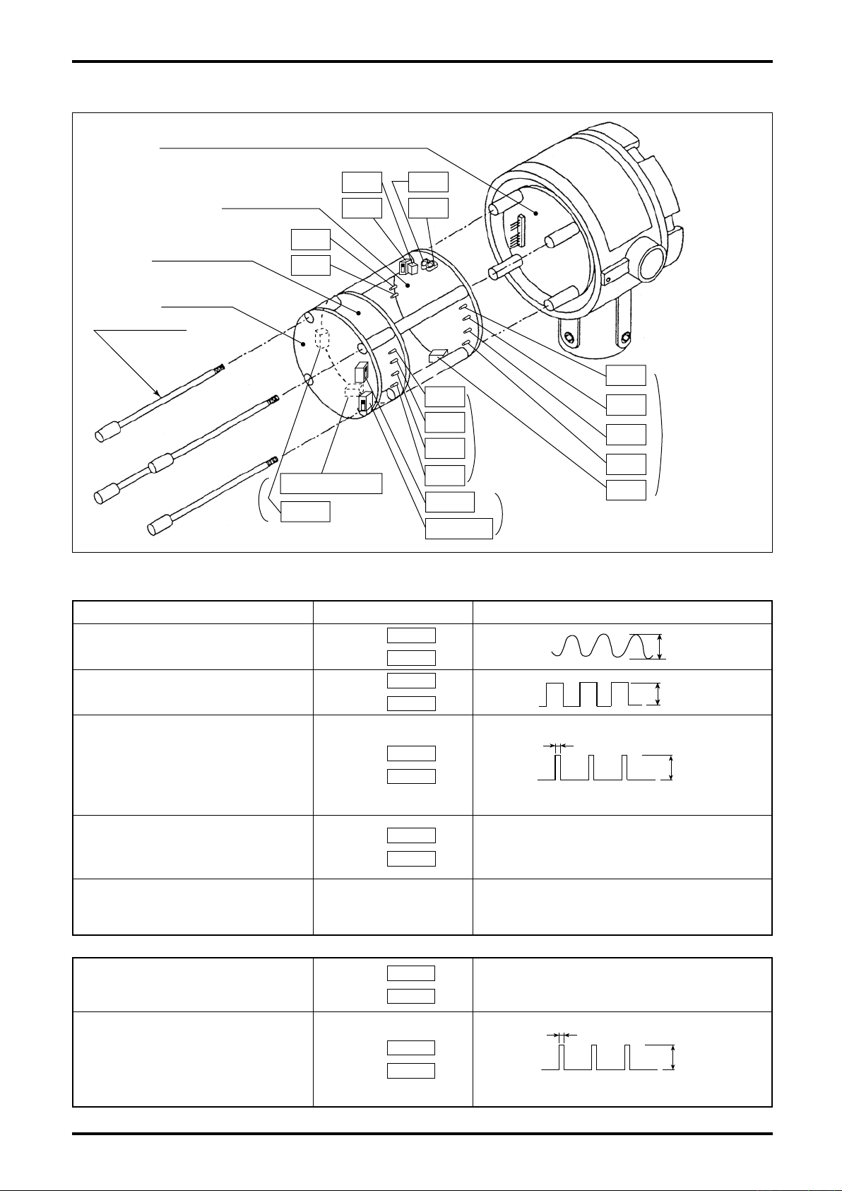
14.3 Preamplifier Inspection
14.3.1 Description of Switches and Potentiometers
(1) Amplifier Board
(2) Isolation Board
36
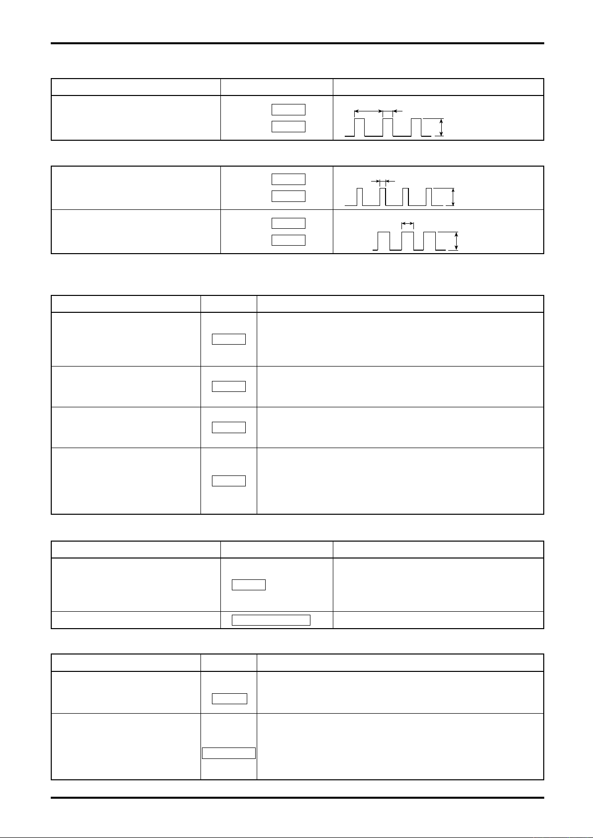
Name Test Pins Description
Amplified vortex waveform
Pulse sync with vortex
Tes t pi n s fo r mo n i t o r ing t h e
pulses sync with vortex
(prior to shaping the pulse width)
Test pins for communication
Notch filter frequency
Select switch
Test pins for entering a simulated
signal input
Tes t p i n s fo r mo n i t oring t h e
pulses after isolation
+・・・
-・・・
+・・・
-・・・
+・・・
-・・・
+・・・
-・・・
NF
+・・・
−・・・
+・・・
−・・・
VTX
0V
TRG
0V
PLS
0V
CM+
CM-
IN
TP-
PL2
TP-
Fig. 14.1
During measurement
During measurement
During
measurement
When 1/2 reduction is turned ON, the period of
this waveform becomes twice that of TRG.
When the communication host is connected
acros s CM + an d CM-, communicati o n is
en able d. (A lo ad r esis tan ce 2 50Ω min . i s
required on the part of receiving instrument.)
0.1Vp-p approx.
3Vp-p approx.
3V approx.
Sets notch filter frequency.
HI : 6300Hz approx.
LO: 3800Hz approx.
Accepts a simulated input equivalent to
open collector pulses or voltage pulses
(PG30).
During
measurement
* Wavefo rm a fter PLS iso latio n on the
amplifier board.
2.7V approx.
Page 37
(3) Isolation Board (analog output type)
20ms
T
2.7Vp-p approx.
T: 2 to 10ms app. at 0 to FS
200 μ s
2.7Vp-p approx.
2.7Vp-p approx.
Depends on "Pulse width" setting.
Name Test pins Description
D-582-3-E
Tes t p i n s f o r mo n itori n g th e
pulses before analog conversion
+・・・
-・・・
OUT
TP-
(4) Isolation Board (pulse output type)
Unfactored pulse output
+・・・
-・・・
+・・・
Factored pulse output
-・・・
OUT
TP-
OUT
TP-
14.3.2 Description of Switches and Potentiometers
(1) Amplifier Board
Name Symbol Description
Amplification factor of the amplifier is factory adjusted
Amplification adjust
potentiometer
Trigger level setting switch
Process fluid and nominal
dia. select switch
1/2 fr eq u e nc y re du c tio n
switch
AMP
TLV
SEL
1/2
relative to the sensor used. Readjustment is basically not
required except when the sensor is replaced with a new one.
See "Flowrate Sensitivity Adjustment Procedure (page 27)."
⇒
Sets the trigger level (pulse generation threshold sensitivity)
to somewhere between 80mV and 350mA p-p.
See "Flowrate Sensitivity Adjustment Procedure (page 27)."
⇒
Selects amplifier characteristics relative to the process fluid
to be metered and nominal meter dia meter. Settings may
vary with flowmeter specifications.
Selects the factor of frequency division or scaling of the
flowrate signal being measured (completely independent of
SEL switch).
OFF: 1/2 reduction inactive
ON : 1/2 reduction active
(2) Isolation Board
Name Symbol Description
Switch for open collector output
Switch for factory testing
(3) CPU Board
Name Symbol Description
Display select switch
(Also serves as total flow
reset switch.)
Parameter overwrite protect
switch
O.C
CALIBRATION
SW1
MODE
SW2
PROTECT
Turning it ON allows an open collector
pulse output to appear across terminals 3
and 2.
*Default setting to be OFF
Set in the OFF at all times.
In case of the totalizer equipped model, selects the totalizer
display menu and resets the total flow.
See "Built-in Indicator Functions and Operation (page 26)."
⇒
Placing the switch in the ON position inhibits attempts to
overwrite parameters through communication.
Reviewi n g th e pa r a m eters t h at h a v e alr e a d y be e n
established, reviewing variables of flow measurement, and
resetting the totalized flow are acceptable, however.
37
Page 38
D-582-3-E
Built-indisplay(option)
1
2
CPU
4
5
6
+
−
LCD
Driver
LCD
(7-segment)
Displayboard
25A〜
15A
1/ 2
CPU board
Isolation board
Amplifier board
Amplifier
board
Interface
board
Interface board
−
TLV
AMP
VTX
TRG
4
5
6
4
5
6
1
2
3
+
TP
+
0V
+4V
-1.5V
0V
TP
-
0V
+1.5V
+4.5V
+2.7V
SW1
SW2
HIC
0V
+
+
OUT
Mo-
dem
Output sig.
select
Analog factored pulse/
Unfactored pulse Select
Low
pulse
cutoff
Amp response select
Divide
Com.
pare
Amp
Chg.
Amp
Chg.
Amp
Piezo-
electric
sensor
Piezo-
electric
sensor
Preamp
board
Separately-mounted Preamp Type
Terminal Block for External Connections
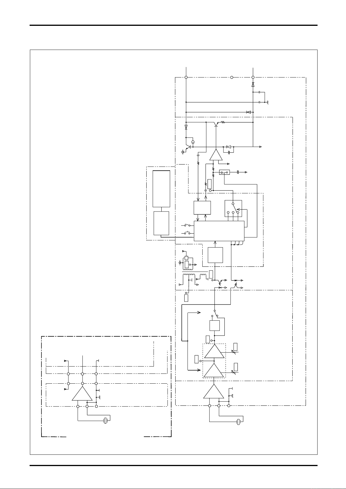
14.3.3 Preamplifier Block Diagram
38
Fig. 14.2 Preamplifier Block Diagram
Page 39
D-582-3-E
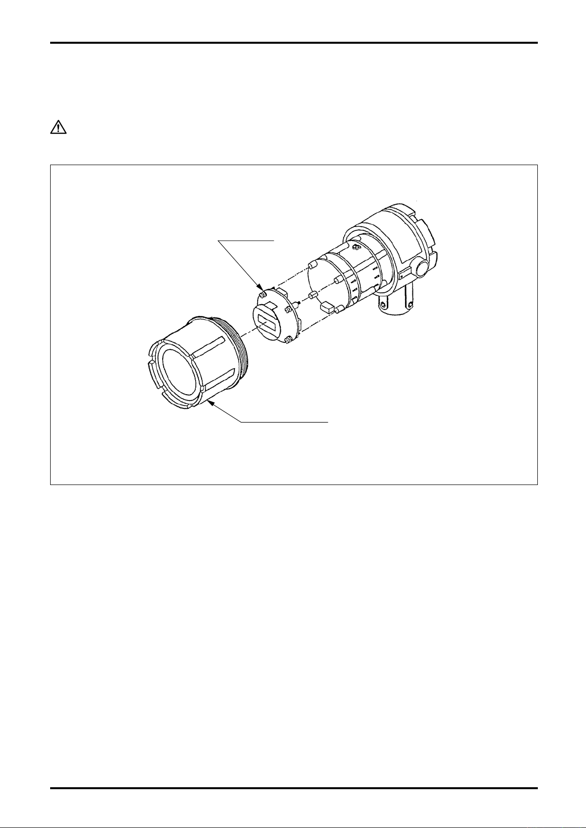
14.4 Display Installation (option)
An optional built-in display (local indicator or totalizer) may be added. Installation is simple by coupling
the indicator unit or totalizer unit to the existing internal assembly.
NOTE: When the display is added, replace the existing cover over the internal assembly with a screw
cover having a glass in the window.
Totalizer Unit
Cover with Window
Fig. 14.3
39
Page 40
D-582-3-E
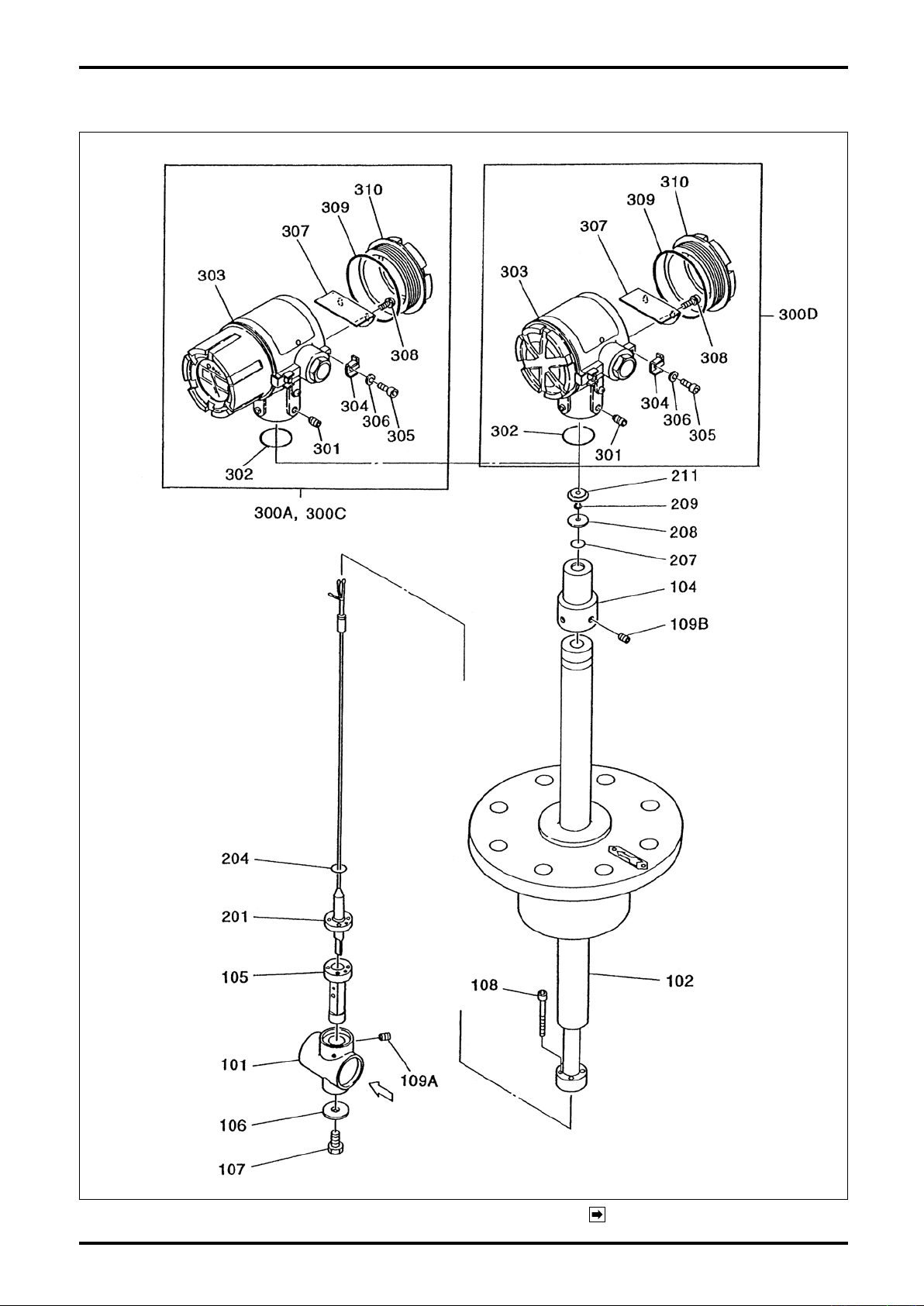
15. EXPLODED VIEW AND PARTS LIST, FIXED TYPE
40
Flow Direction
Fig. 15.1
Parts list appears on the next page.
Page 41
D-582-3-E
● Parts List
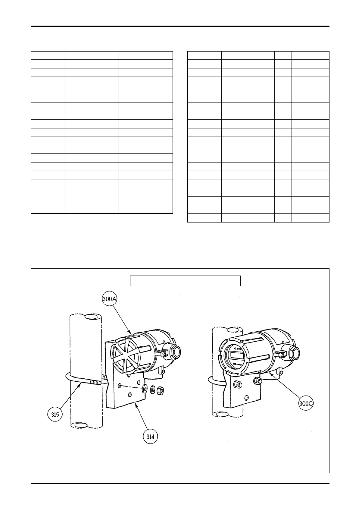
Sym.No. Part Name Q'ty Remarks Sym.No. Part Name Q'ty Remarks
101 Probe Body 1 300A Preamplifier 1 PA25
102 Shaft Assembly 1 Fitting flange 300C
104 Fitting Boss 1 300D Terminal Box 1
105 Bluff Body 1 311
106 Spacer 1 312 Totalizer Assembly 1 See page 40.
107 Hex Bolt 1 M10×10 301 Hex Socket Head
108
109A
109B
201 Sensor 1 304 Latch 2
☆204 O-Ring 1 305 Hex Socket Head
207 O-Ring 1 P10A
208 O-Ring Retainer 1 306 Spring Washer B 2
209
211 Retaining Ring 1 308 Pan Head Screw 2 M3×6
212 Gasket 1 For pream
214
NOTE: Material of O-ring (204) varies with the chemical
properties of the process fluid.
Hex Socket Head Bolt
Hex Socket Head Screw
Hex Socket Head Screw
"C" Stop Ring for Shaft
Preamp Fitting Screw
4 M5×30
3 M6×8 302 O-Ring B 1 JASO-2033
4 M6×8 303
1 Nom. dia. 10 307 Shield Strip 1
309 O-Ring C 2 AS568-233
PA45
4 314 Fitting 1
310 Terminal Box Cover 1
315 U-Bolt 1 Not provided
Preamplifier w/ Totalizer
Preamplifier Assembly
Screw B
Preamplifier Housing
Bolt D
1 PA25S
1 See page 40.
4 M8×10
(nominal 4)
1
Explosionproof
2 M4×6
(nominal 3)
Nom. 4 (Fits M4)
Separately-mounted Preamplifier
Fig. 15.2
41
Page 42
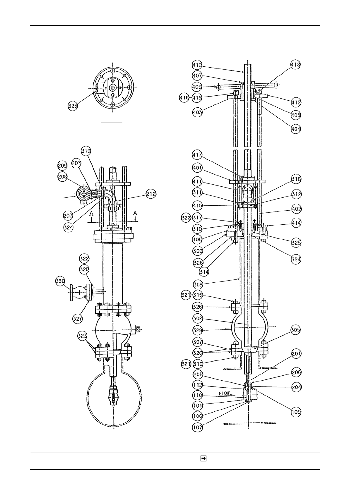
D-582-3-E
16. ASSEMBLY DRAWING AND PARTS LIST, HOTTAP TYPE
Sec. A-A
Preamp
42
Fig. 16.1
NOTE: Parts list appears on the next page.
Page 43

D-582-3-E
● Parts List
〈Probe Assembly〉 〈Drive Assembly〉
Sym.No. Part Name Q'ty Remarks Sym.No. Part Name Q'ty Remarks
101 Probe Body 1 400 Drive Unit 1 set (401 to 418)
106 Spacer 1 401 Guide 1
107 Hex Bolt 1 402 Stud 4
109
110 Bluff Body 1 404 Rotor 1
112 O-Ring 1 405 Collar A 1
201 Sensor 1 set 406 Handwheel 1
202 Locating Pin 1 407 Nut 1
203 Adaptor B 1 408 Stud Mounting Disc 1
☆204 O-Ring 1 P16 410 Screw Shaft 1
206
207 O-Ring 1 P10A 412 Collar B 1
208 O-Ring Retainer 1 414 Hex Bolt 3 M16×35
209
212 Rubber Bushing 1 416 Washer 4 M16
NOTE: Material of O-ring (204) varies with the chemical
properties of the process fluid.
Hex Socket Head Screw
Hex Socket Head Bolt
"C" Stop Ring for Shaft
3 M6×8 403 Cover B 1
4 M5×30 411 Connecting Stud 2
1 415 Hex Nut 6 M16
417
418 Protection Cap 4
Hex Socket Head Bolt
2 M8×25
〈Control Assembly〉
Sym.No. Part Name Q'ty Remarks
302 Shaft 1
305 Retaining Ring 1
307 Hold-down Disc 1
308 Short Pipe 1
309 Cover 1
310 Gasket Retainer 1
311 Adaptor A 1
312 Fitting 2
314 Hex Bolt 8 M16×45
315 Hex Bolt 8 M16×55
316 Through Bolt 8 M16×100
317 Stud Bolt 2 M12×50
318
319
320 Hex Bolt 4 M12×40
321 Hex Nut 24 M16
322 Hex Nut 6 M12
323 Arrow Plate 3
324 O-Ring 2 P40
325 Gland Packing 5
326 Flange Gasket 4
327 Flange Gasket 1
329 Gate Valve 1
330 Vent Valve 1
Hex Socket Head Bolt
Hex Socket Head Bolt
4 M8×30
4 M4×15
43
Page 44

D-582-3-E
17. GENERAL SPECIFICATIONS
17.1 Sensor Specifications
Table 17.1
ITEM DESCRIPTON
Installation Fixed type Hottap type
Pipe Nominal Dia.
Probe Nom. Bore 50mm
Meter Body SUS304
Materials
Bluff Body SUS304
Pressure Ratings JIS 10K, ASME 150, JPI 150
Flange Rating 100mm (4″) JIS 10K, ASME 150, JPI 150
Orientation Horizontal or vertical pipeline Horizontal pipeline
Max. Operating Pressure
Operating Temp.
Range ☆
Fluid Velocities
Standard Insersion
Depth
Accuracy ★ Better than±2% of full scale
Acceptable Fluid
200,250,300,400,500,600,
800,1000,1500,2000mm
Depends on flange rating
-10 to +300℃
Air (atm. pressure):12 to 50m/s
Water:0.6 to 6m/s
Pipe nominal bore D < 500mm: 0.5D approx.
Pipe nominal bore D≧500mm: 0.2D approx.
(where D = pipe nominal bore, mm)
Liquid (water, hot water, chemical liquids)
Gas (gases in general, compressed air, etc.)
Steam (saturated steam, superheated steam)
400,500,600,800,
1000,1500,2000mm
☆:Operating temperature range varies according to fluid conditions.
★:The stated accuracy is guaranteed only when used under the metering specifications (contributing factors
such as the pipe inside diameter and fluid conditions).
NOTES: See meter tag or approval drawing for the operating flow ranges and preamplifier output
specifications.
44
Page 45
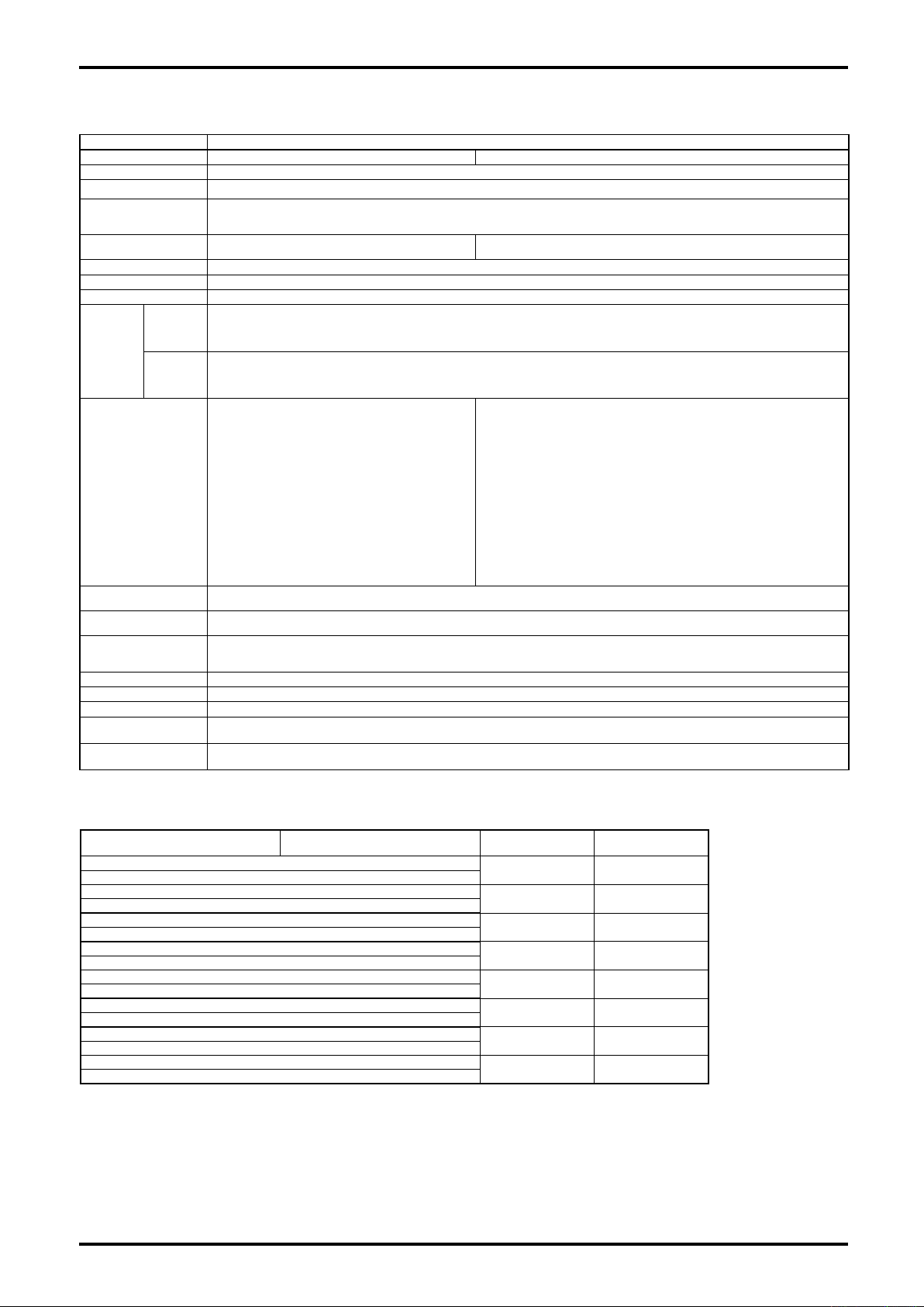
D-582-3-E
17.2 Preamplifier Specifications
Model PA25 (No Display) PA25S (w/Totalizer, Digital Indicator)
Mounting Select one of the followings : ① Integral with flowmeter ② Separate type (installed on 2″ pipe)
Waterproof configuration
Explosionproof
configuration
Ambient temperature
Ambient humidity 5 to 100%RH without dew condensation
Material Aluminum alloy
Housing finish Finished in baked melamine Finish Munsell 10B8/4 (Cover:Munsell 2.5PB4/10)
Output
(Choose
any)
Display (Option)
Power supply
Cable entry
Cable (※1)
Transmission length Converter to receiving instrument : 1km Max Sensor to converter : 200m Max (applicable to separate type)
Communication HART Protocol Communication (※ 3)
Computation
Applicable
EU Directives
Applicable
EN Standards
Item Description
(※1)
Current
signal
Open
collecter
IP66 (dusttight/weathertight)
Select one of the followings :
① Non-explosionproof configuration ③ Flameproof configuration ATEX: II2G Exd IIB+H2T1 to T6
② Flameproof configuration TIIS: Exd IIB+H2T4 ④ Flameproof configuration GOST:1Exd IIB+H2T1 to T6
Non-explosionproof configuration : -40 to +80˚C
Explosionproof configuration : -20 to +60˚C
2-wires system (Both as Power line) Select one of the followings : (※ 4 )
① Scaled pulse Pulse level : 0/1 = 4/20mADC Pulse width : 10 to 1000ms (St'd : 50ms)
② Unscaled pulse (Vortex synchro-nized pulse) Pulse level : 0/1 = 4/20mADC Pulse width : 200 μs
③ Analog 4 to 20mADC at 0 to FS Time constant : 0 to 100s (St'd : 2.5s)
3-wire type, NPN transistor output (Max. impressed voltage: 30VDC, Allowable current: 50mA, ON
voltage: 1.5VDC or less)
① Compensated pulse (factored pulse), Pulse width: 10 to 1000ms (Standard 50ms)
② Uncompensated pulse (vortex synchronized pulse), Pulse width: 200 μ s
—
12 to 45V DC (See Load Resistance Range curve)
NOTE: If you connect OVAL communication unit EL2310, use a power supply below 33V DC.
G1/2 internal threads
External cable lead-in method for the flameproof configuration: pressure-tight gasket (furnished with lead-in metal clasp)
Converter to receiving instrument : 1.25mm2 Min., 2-conductor shield cable
Sensor to converter : 1.25mm2 Min., 3-conductor shield cable (applicable to separate type)
Finished cable outside diameter : Non-explosionproof φ13.5mm Max Flameproof φ 8.5 to φ11mm
・Actual flow rate computation (Liquid, Gas, Steam) ・Temp./Press. correcting computation (Gas)
EMC :2014/30/EU
ATEX:94/9/EC
EMC :EN61326-1:2013 Class A
ATEX:EN60079-0:2006, EN60079-1:2007
-IEC/EN 60529, JIS C 0920 -- NEMA TYPE 4X
Table 17.2
Display : 7 segments LCD
Content : One of the following 4 ways display is possible with switching
over of an internal switch or a EL2310
①
Unit of totalizing : Same as scaled pulse output
Unit of flow rate indication : Refer to (※ 2)
・Upon power interruption, Totalized counts are held by
nonvolatized memory
・Totalized counts are resettable by an internal switch or (Option)
EL2310
②
Unit of flow rate indication : Refer to (※ 2)
③
Unit of display : % FS Discrimination : 0.1%
Full scale : Same as that of analog output
④
Display : % FS Full scale : Same as that of Analog output
Non-explosionproof configuration : -20 to +60˚C
Explosionproof configuration : -20 to +60˚C
Totalizing flow throughput : 6 digits
Instantaneous flow rate : 7 digits(3 1/2 digits are effective)
% Instantaneous flow rate :
8 scaled % Bar graph
(※ 1): In case of TIIS explosionproof type used under the ambient temperature of 50℃ or higher, use a cable resistant to the
temperature of 70℃ or higher.
(※ 2): Unit of Totalized flow counts of Flow and Instantaneous Flow rate Indication can be selected from following table.
Unit of Indicated Flow Rate
L/min, L/h, m3/min, m3/h, kL/min, kL/h
L, m3, kL
L/min [normal], L/h [normal], m3/min [normal], m3/h [normal]
L [normal], m3 [normal]
g/min, g/h, kg/min, kg/h, t/min, t/h
g, kg, t
ton (US)/min, ton (US)/h
ton (US)
gal(US)/min, gal(US)/h
gal(US)
ft3/sec, ft3/min, ft3/h
3
ft
SCFS(=ft3/sec[standard]), SDFM(=ft3/min[standard]), SCFS(=ft3/h[standard])
SCFT(=ft3[standard])
lb/min, lb/h
lb
(※ 3)
: In case a specification for Pulse output is given, Communication function is available only under the following conditions:
Top: Instantaneous flowrate units
Bottom: Total flow units
Calculation
on actual flow
○ ×
× ○
○ ○
○ ○
○ ×
○ ×
× ○
○ ○
Calculation corrected
for temp. and press.
① During flow interruption
② Upon Power“ON” (Continuous communication is available if starts within 15 sec. after Power“ON”)
(※ 4)
: If you desire to transform the factored or unfactored pulse output into an open collector output, consult the factory.
●
Guidelines to set the analog output and indicator full scale are given below:
3 times the minimum flowrate ≦ Full scale ≦ 1.3 times the max. flowrate.
For minimum and maximum flowrates, refer to the section "Flow Ranges".
If you want to set up a full scale outside the range above, consult the factory.
45
Page 46

D-582-3-E
17.3 Nominal Meter Factors
Table 17.3
Pipe Nominal Bore, mm (inches) Nominal Meter Factor, L/P
200 ( 8) 2.42
250 (10) 3.89
300 (12) 5.75
400 (16) 10.7
500 (20) 18.9
600 (24) 27.7
800 (30) 49.2
1000 (40) 76.9
1500 (60) 173
2000 (80) 309
46
Page 47
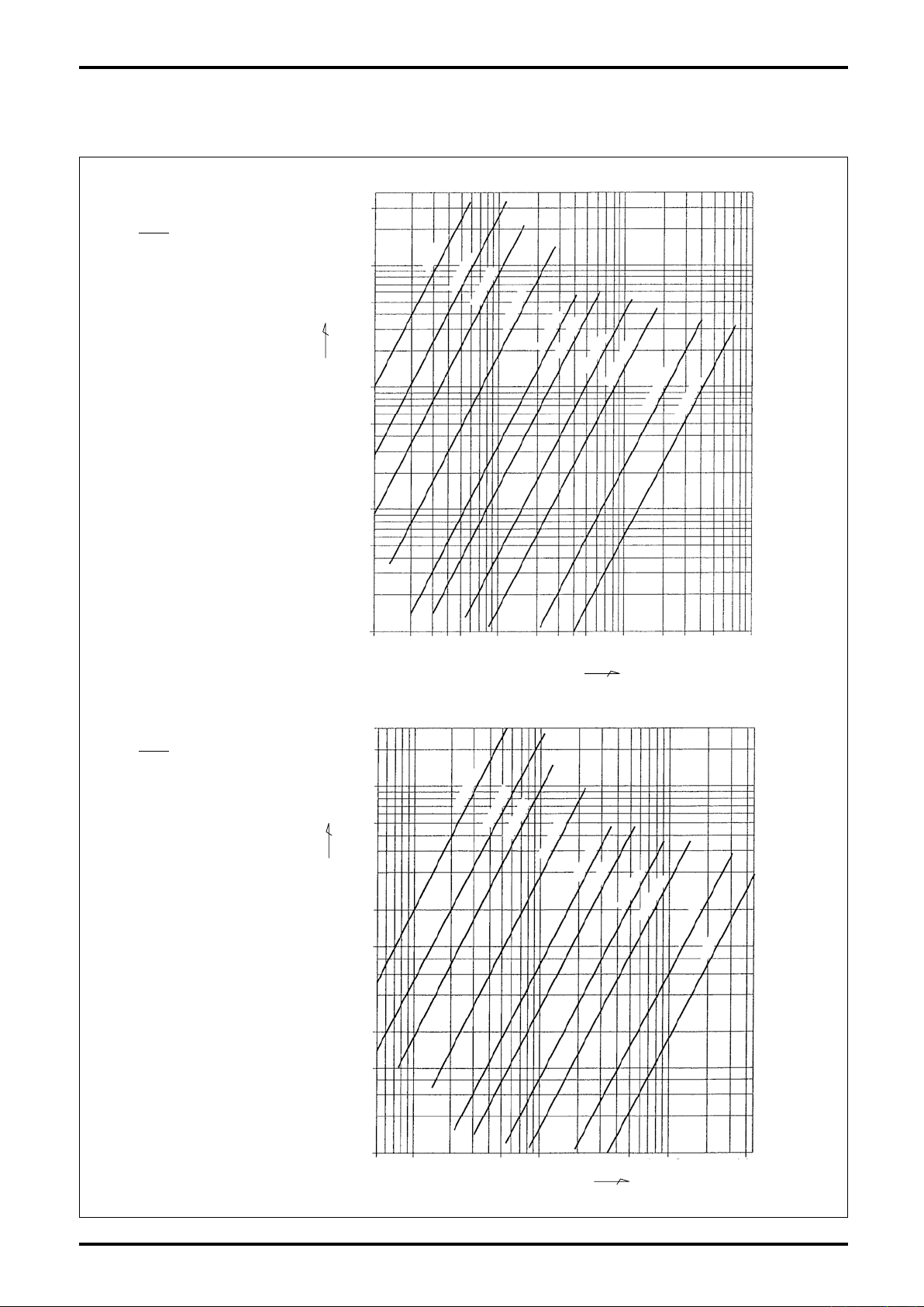
17.4 Pressure Losses
30
10
5
1
0.5
0.1
0.05
0.01
500 1000 500 10
4
10
5
5×10
4
4×10
5
200mm
250mm
300mm
400mm
500mm
600mm
800mm
1000mm
1500mm
2000mm
Flowrate(m3/h)
PressureLossCoeffofLiquids,C
300
100
50
10
5
1
0.5
0.1
100 200 300 500 1000 2000
3000 10000 30000
5000 20000 50000 10
5
Flowrate(m3/h)
200mm
250mm
300mm
200mm
400mm
500mm
800mm
1000mm
1500mm
2000mm
PressureLossCoeffofLiquids,C
● Liquid Service
C×ρ
△P=
5
10
△P=Pressure loss(kPa)
ρ=Density(kg/m3)
D-582-3-E
● Gas and Steam Service
C×ρ
△P=
100
△P=Pressure loss(kPa)
ρ=Density(kg/m3)
47
Page 48
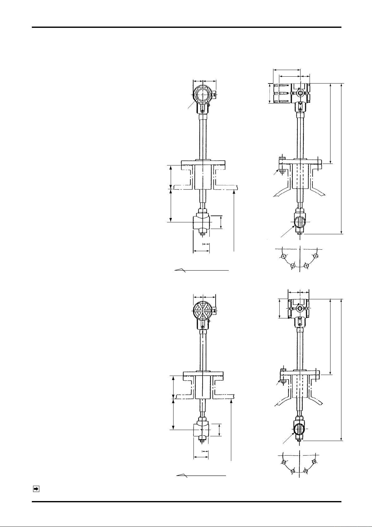
D-582-3-E
76
φ57
44 60
55 41
Y
Ln(100)
φ88
L3≒627-Ln-Y
673
25
Pipe Inside Dia.φD
Flow Direction
MTG. Flange
Probe
MTG. Flange
76
φ57
Probe
44
Built-in Display
60
100
(126)
41
Y L
n
(100)
φ88
L3≒627-Ln-Y
673
25
Flow Direction
Pipe Inside Dia.φD
18. OUTLINE DIMENSIONS
18.1 EX DELTAⅡ
● Fixed Type
Preamplifier:Integrally-mounted type
Applicable pipe nominal bore:200 to 1300mm
(If nominal size of the pipe exceeds 1300mm,
different dimensions will apply.
Please consult OVAL)
Ln=Mounting nozzle length(std.100mm)
Y =Insertion length
Standard Pipe nom. bore<500mm
0.5D approx.
Pipe nom. bore≧500mm
0.2D approx.
(
Where D=Pipe nominal bore
Confirm the actual insertion length on
the delivery specifcation.
All dimensions millmeters
NOTE: Figures in brackets( )show meter with built-in display.
)
● Fixed Type
0.5D approx.
(
Preamplifier:Separately-mounted type
Applicable pipe nominal bore:200 to 1300mm
(If nominal size of the pipe exceeds 1300mm,
)
different dimensions will apply.
Please consult OVAL)
Ln=Mounting nozzle length(std.100mm)
Y =Insertion length
Standard Pipe nom. bore<500mm
Pipe nom. bore≧500mm
0.2D approx.
Where D=Pipe nominal bore
NOTE: See approval drawing for detail dimensions.
48
Page 49
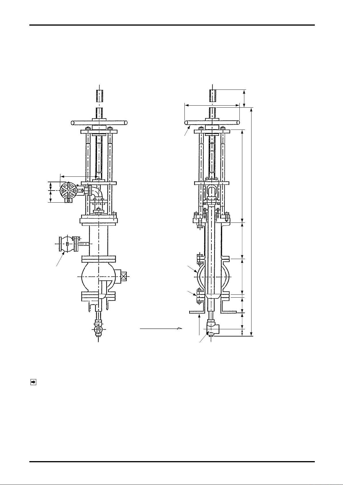
Travel Distance:Ls
(Ls=Ln+Y+298)
φ355
Handwheel
216
Gate Valve
(Nom. Bore100mm)
Gate Valve,
Face to Face:Lv
(Std. 229)
Mtg. Nozzle
Length:Ln(Std.:100)
Insertion Length:Y
(0.2D approx. or
0.5D approx.)
Vent Valve
Hold-Down Disc
989400
60 44
LvLnY
46.5
φD
16 2110
Probe
(Pipe I.D.)
Flow Direction
● Hottap Type
Applicable pipe nominal bore:400 to 1000mm
(If nominal size of the pipe exceeds 1000mm,
different dimensions will apply. Please consult OVAL)
D-582-3-E
All dimensions millmeters
NOTE: See approval drawing for detail dimensions.
49
Page 50
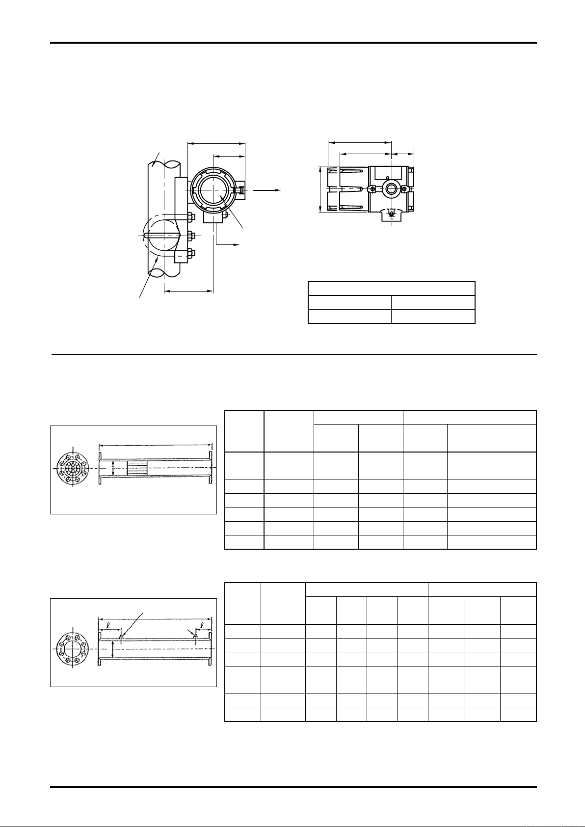
D-582-3-E
109
60
100
92.5
φ88
41
(126)
Built-in Display
Installation on a horizontal
pipe is shown here.
To Receiving
Instrument
To Sensor
2″Pipe
L
φd
Gage Tap Rc3/8
Thermometer
Tap Rc3/4
φd
21
18.2 Separately-Mounted Preamplifier
All dimensions in millimeters
NOTE: Figures in brackets ( )show
meter with built-in display.
Approx. Weight(kg)
Less Display Display Provided
1.9 2.1
18.3 Flow Straightener and Downstream Pipe
Flow Straitener Outline Dimensions
Model
FS
FS
FS
Nominal dia.:100mm max.
Downstream Short Pipe Outline Dims.
Nominal dia.:150mm min.
FS
FS
FS
FS
NOTE: ※ Above 400mm, ASME Class 150 only.
Model
SP
SP
SP
SP
SP
SP
SP
NOTE: ※ Above 400mm, ASME Class 150 only.
Nom. Dia.
mm
(Inches)
2
200(8) 199.9 2,400 130 140 160
20
3
2
25 250(10) 248.8 3,000 220 240 270
3
2
30 300(12) 297.9 3,600 340 370 410
3
2
35 350(14) 333.4 4,200 470 510 570
3
2
40 400(16) 390.6 4,800 490 520※ ─
3
2
50 500(20) 489.0 6,000 870 930※ ─
3
2
60
600(24) 584.2 7,200 1,590 1,670※ ─
3
Nom. Dia.
mm
(Inches)
2
200(8) 199.9 1,000 400 200 58 70 92
20
3
2
25 250(10) 248.8 1,250 500 250 100 120 150
3
2
3
2
3
2
3
2
3
2
3
30 300(12) 297.9 1,500 600 300 150 180 220
35 350(14) 333.4 1,750 700 350 210 250 310
40 400(16) 390.6 2,000 800 400 210 250※ ─
50 500(20) 489.0 2,500 1,000 500 370 420※ ─
60
600(24) 584.2 3,000 1,200 600 670 750※ ─
Dimension mm Approx. Weight(kg)
φd L JIS 10K
JIS 20K
ASME Class 150
Dimension mm Approx. Weight(kg)
φd L ℓ1 ℓ2 JIS 10K
JIS 20K
ASME Class 150
JIS 30K
ASME Class 300
JIS 30K
ASME Class 300
50
Page 51
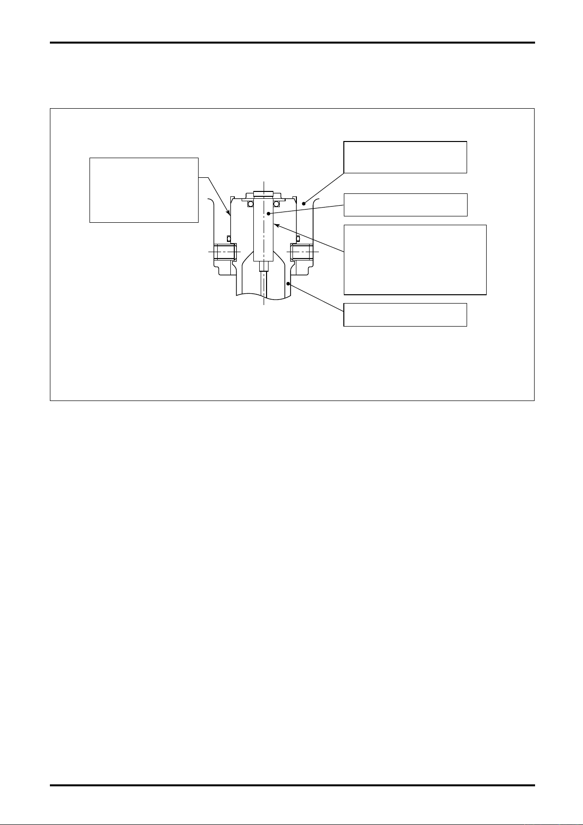
D-582-3-E
CASINGFORINTEGRALLY
MOUNTEDMODEL
MATERIAL:ALUMINUMALLOY
TERMINALBLOCK
MATERIAL:STAINLESSSTEEL
FLAMEPROOFJOINTINFO.
HOLE:φ10
SHAFT:φ10
MAX.GAP:W=0.13
WIDTH:L=17.3±1.3(PA25-C05)
WIDTH:L=24.8±1.3(PA25-C07)
SURFACEROUGHNESS
:BETTERTHAN6.3a
+0.10
+0.05
0
−0.03
FLAMEPROOFJOINTINFO.
HOLE:φ33.5
SHAFT:φ33.5
MAX.GAP:W=0.124
WIDTH:19
SURFACEROUGHNESS
:BETTERTHAN6.3a
+0.062
0
−0.005
−0.062
+0.6
−0.8
PROTECTIVECYLINDER
MATERIAL:STAINLESSSTEEL
19. FLAMEPROOF APPROVAL : DIMENSION OF NON-THREADED JOINTS
Dimensions of the "non-threaded joints" concerning the flameproof configuration are show below.
For mounting of protective cylinder to casing use hexagon socket set screws M8×10,
stainless steel A70.
Fig. 19.1
51
Page 52
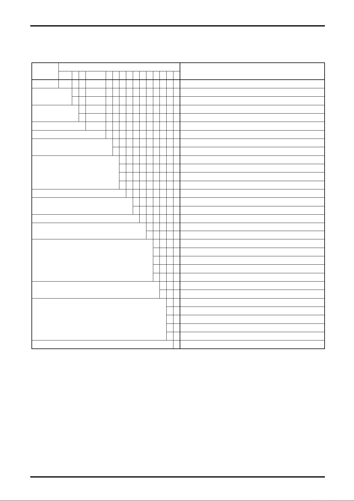
D-582-3-E
19. PRODUCT CODE EXPLANATION
Table 19.1
Item
Model V X EX DELTAⅡ
Body Style
Application
No minal D ia. 0 5 0 50mm(2″)
Major Parts Material
Flange Rating
Sensor Construction 1 Standard
Fluids to be Metered
Preamplifier Construction
Explosionproof configuration
Display
Output Signal
Version Code C
①② ③ ④ ⑤ ⑥ ⑦ - ⑧ ⑨ ⑩ ⑪ - ⑫ ⑬ ⑭ ⑮ ⑯
S In-line, fixed type
H In-line, hottap type
1 Standard (+180℃ max.)
3 High temperature service (above +180℃ )
Product Code
-
D SUS304 or equiv.
Z Other than above
1 JIS 10K
5 ASME 150 (※1)
7 JPI 150
9 Other than above
G Gas and steam
L Liquid
-
1 Integrally-mounted type
2 Separately-mounted type
0 None (non-explosionproof)
1 Flameproof configuration (TIIS) (※2)
2 Flameproof configuration (ATEX)
A Flameproof configuration (GOST)
7 Flameproof configuration (NEPSI)
0 None
1 Totalizer, digital indicator (※3)
4 Unfactored pulse: Smart
5 Factored pulse: Smart
6 Analog: Smart
D Unfactored pulse (open collector pulse)
E Factored pulse (open collector pulse)
Description
NOTES:
52
※1. ASME rated meters are supplied with serrated flanges conforming to ASME B 16.5-1996.
※2. Explosionproof rated meters are provided with dedicated explosionproof cable gland
(pressuretight gasket).
※3. Information displayed is selectable by an internal switch or by SCU for one from ① 6-digit
total counter, ② digital instantaneous flowrate, ③ %instantaneous flowrate, and ④ 8-section
bar graph.
Page 53
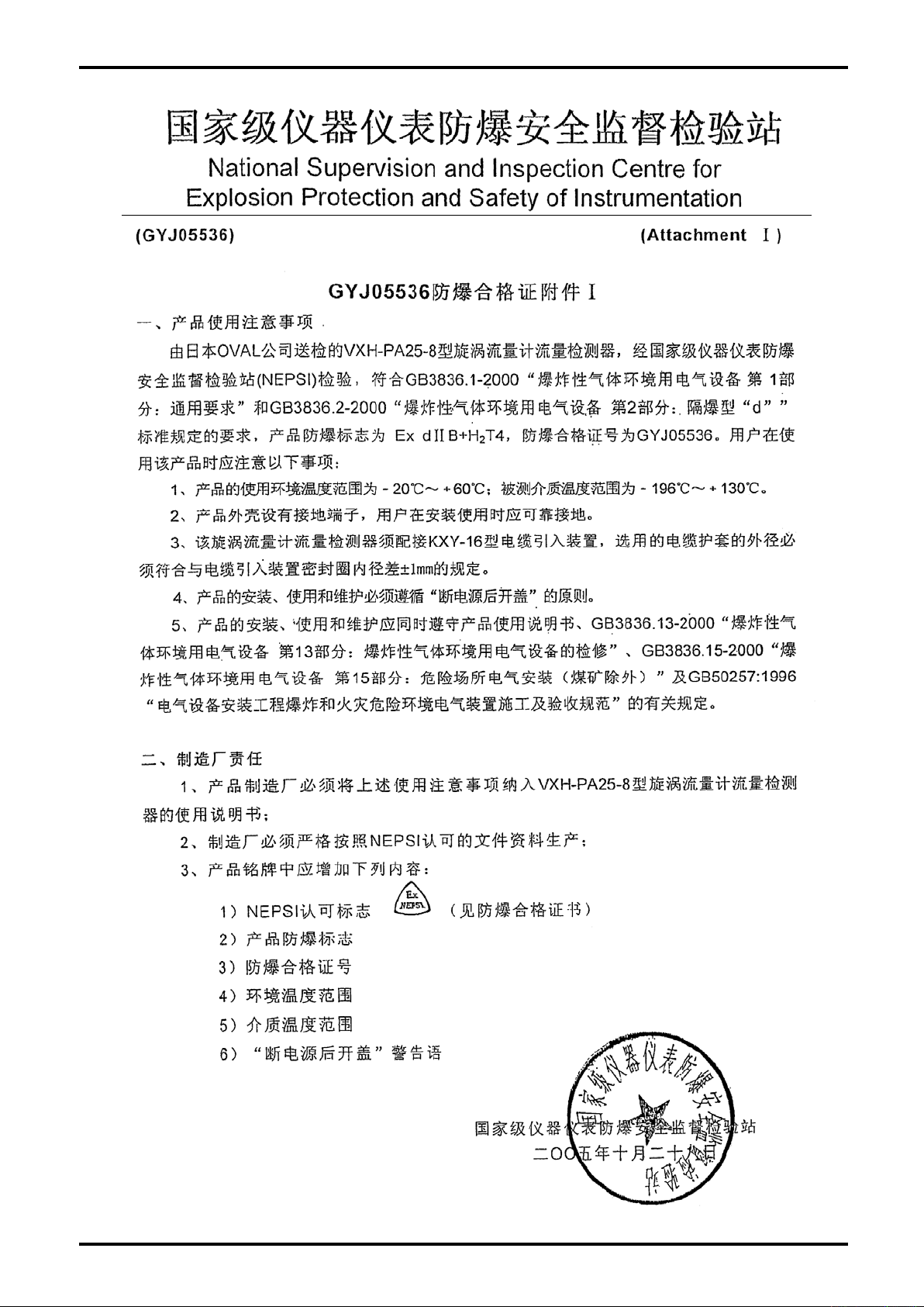
D-582-3-E
53
Page 54

D-582-3-E
Allspecificationsaresubjecttochangewithoutnoticeforimprovement.
2017.02 Revised
2015.08 Revised △
2013.07 Released
D-582-3-E (2)
 Loading...