

Page 1
Ins. No.
T-518-11-E
NONCONTACT PULSE GENERATORS
MODEL PG30/PG30EP
GENERAL
■
When used in conjunction with an OVAL flowmeter, the Model PG30/
PG30EP noncontact pulse generator provides voltage frequency pulses
proportional to the flowrate of process fluid. Incorporated in the pulse
generator are a premolded pulse generating element and a circuit
which prevents false pulses otherwise generated by minute vibration
of generator components. As the toothed disk rotates, a succession of
voltage pulses (quasi rectangular wave) is generated.
Generated pulses come either pulses in scaled units or unscaled
pulses, depending on the position of flowmeter at which the generator
is mounted. Pulses in scaled units can be used in remote totalizing,
batching, blending systems and the like built around an OVAL flowmeter
which serves as the sensing terminal. Unscaled pulses are converted
into an analog signal for use in flow indicator/recorder/controller
applications. Models PG30S/PG30SEP are compatible in the latter
applications.
★ For complete details of Models PG30S/PG30SEP,see OVAL Products
General Specifications GS No T-523-E.
MODEL PG30
MODEL PG30EP
Pulse generators come in the following two designs:
(1)Standard type……PG30
(2)Flameproof type…PG30EP (designed and fabricated according to the "Explosionproof Guide-
lines" recommended by the Technology Institution of Industrial Safety.)
Information about Models PG30S and PG30SEP appears in Instruction Manual No. T-523-E.
★
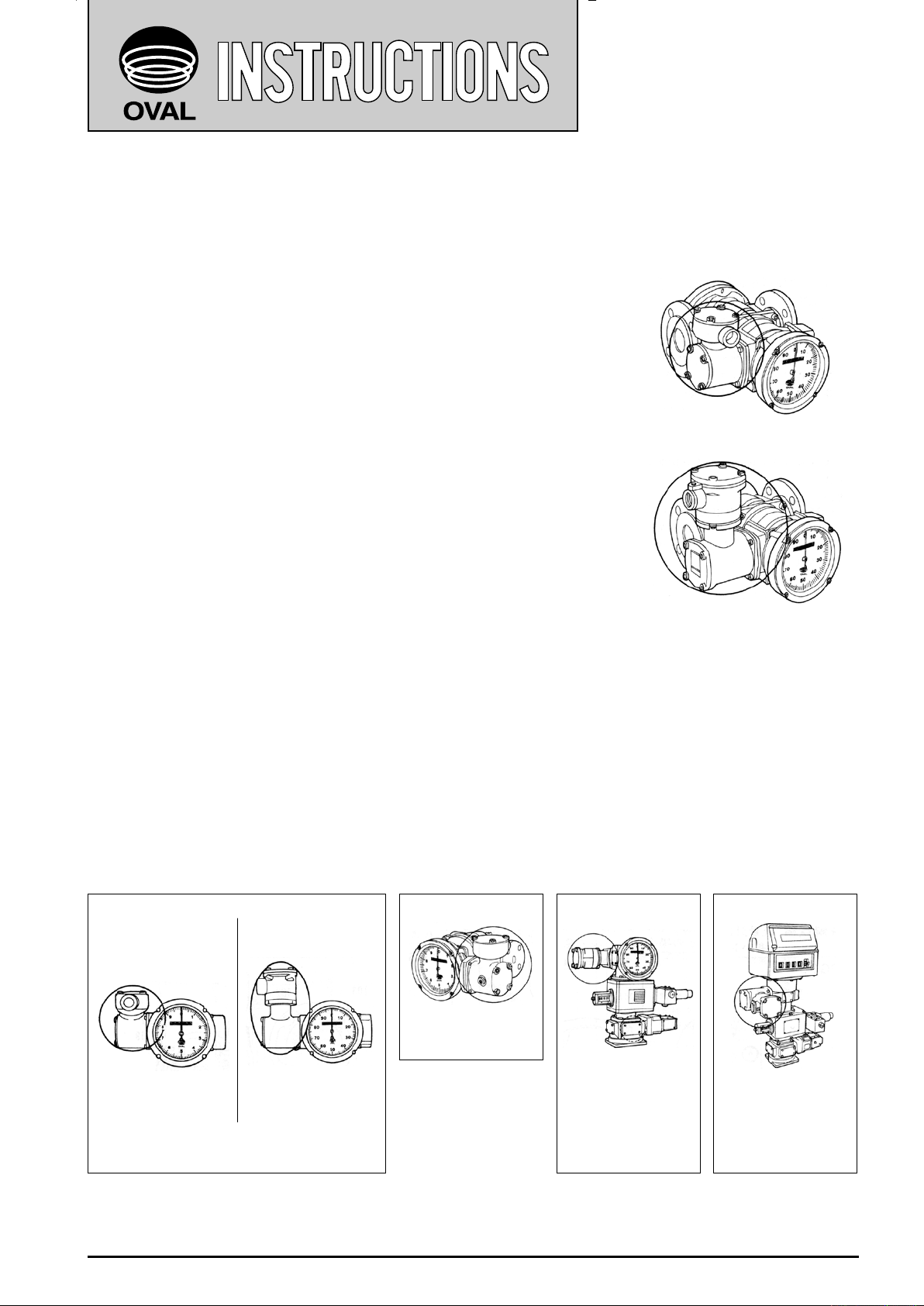
PULSE GENERATOR INSTALLATION EXAMPLES
■
Generated pulses in scaled units…The rotor revolution is guided into gear reduction and instrumental
error correction stages for the flowmeter to produce pulses of required scaled unit. The obtained pulse
signal is used primarily for remote totalization.
GB type
Pulse generator
for totalizer
Where pulses of scaled units or
unscaled pulses are required
Pulse generator
for totalizer
LW13 type CB type PB type
Meter sizes 52 or 53;
where pulses in scaled
units are required.
If unscaled pulses
uncompensated for
temperature are required, it is mounted to
the area encircled ( ○ )
of transmission gear
box GB.
Equipped with register Model LW11;where
pulses of scaled units
compensated for temperature are required.
Equipped with register Model LW42 or
43;where pulses of
scaled units compensated for temperature are required.
Page 2

T-518-11-E
Receivecoil
Sendcoil
Waveform
Tootheddisk
HF
Oscillator
Detector
Recti-
fier
Waveshape
L
1
L
2
① ② ③ ④
(BLK)
(WHT)
Power+12V
OutputSIG
Power0V
(RED)
Send
coil
Receive
coil
V1
V1
V2
Output
(Output =V1XORV2)
Tootheddisk
V1
V2 V2
OPERATING PRINCIPLE
■
1. Operation can best be understood by referring to Fig.1. Oscillator coil L1 in the HF oscillator continuously
generates a 1MHz high frequency wave (waveform ① ). As a toothed disk, located between the coil and
detector rotates, a high frequency induction field created is intermittently interrupted. The resultant signal
induced in pickup coil L2 of detector is a wave modulated by the toothed disk (waveform ② ). The signal is
then detected(waveform ③ ) and further shaped into a rectangular signal (waveform ④ ).
Hysteresis characteristics are also provided electrically by changing trigger levels at the leading edge and
trailing edge of the signal.
2. Fig.2 shows how our proprietary double pulse generator works. With two pairs of HF send/receive coils
arranged opposite to each other, intermittent interruption of the magnetic field takes place by the rotating
toothed disk and causes each coil to produce a single pulse per gap (or slot) between the teeth.
Because two coils are so located as to produce pulses 90°out of phase from each other, by exclusive OR (XOR)
of pulses from these two coils, two pulses per gap between the teeth are obtained after all.
WIRING INSTRUCTIONS
■
1. Cables for eld wiring
Recommended cables for field wiring are 3-conductor, shielded, chloroprene cabtyre cables [kind 2] (JIS C
3311) or 2-conductor, shielded, vinyl cabtyre cables (JIS C 3312) 1.25mm2 to 2.0mm2 in conductor area unless
otherwise specified.
2. Transmission Length
The maximum Transmission length is one kilometer when cables 2mm2 in conductor area conforming to JIS C
3311 or C3312 are used.
NOTE: If it exceeds one kilometer, consult the factory.
3. Conduit work is suggested.
Cable connections: PG30 ……Rc (PT) 3/4 female
PG30EP…G (PF) 3/4 female
NOTE: With conduit, a minimum of five full threads should engage the mating thread.
Wiring connections
Remove the lid of PG30/PG30EP housing to gain access to
a 3-post terminal block. Terminal identification label is found
on the reverse side of the lid. Remove a wiring connection
instruction label put on the terminals.
1 → +12V WHT
Terminal No. 2 → SIG RED
3 → 0V BLK
If grounding at the pulse generator end is desired
With PG30EP, use the earth ground terminal furnished.
With PG30, no ground terminal is provided; take off a screw
as shown in Fig 3 and earth ground using a terminal lug.
2
Fig. 1
Fig. 2
Ground this terminal if
required.
Fig. 3
Page 3
T-518-11-E
23
1
SIG0V
MODEL
PG30, PG30EP
12VDC
+12V
10k
Ω
a
+
b
C
0
1
D
4. Conduit work for Model PG30EP (ameproof type)
(1) Use steel conduit conforming to the requirements specified in JIS C 8305.
(2) Conduit accessories should be of flameproof rating.
(3) Sealing work should be taken into consideration.
(4) Where rusting the screw threads is anticipated, apply a coat of non-drying sealing compound externally
following the screw engagement of conduit.
5. Inductive Interference Prevention
Field wiring should be routed sufficiently away from existing power cables or power circuits, if any, to prevent
potential stray current pickup.
If you want to use both scaled unit pulses and unscaled pulses, use two separate cables.
DISASSEMBLY AND INSPECTION
■
The pulse generator should be disassembled for inspection once a year.
◎
(Make sure that the transmitter cables are not lodged between the casing parts while reassembling.)
If there is no or few (or too many) pulses from the pulse generator while the flowmeter register pointer moves or
the counter operates properly, trouble is suspected in the pulse generator. Inspect its components according to
the procedure described below.
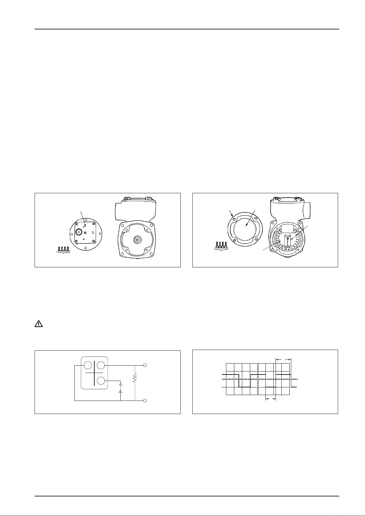
PG30 PG30
Transmission gear box
167
1. Remove the pulse generator from the flowmeter.
Take off four screws (167) to gain access to the
transmission gear box. Check for any gear slipping
on its shaft or crimp connections that are loose.
2. Take off four screws (139) holding the housing lid
(102) in place and remove the lid.
Check to see that toothed disk (116) turns smoothly
and that the brake shoe (119) works properly.
103 102
139
119
116
Fig. 5Fig. 4
The same procedure applies to Model PG30EP.
CAUTION: If something is wrong with spring (122) and/or brake shoe (119), replace the whole brake
shoe assembly (plate (120) inclusive).
Monitoring the Output Waveform
●
Fig. 7Fig. 6
Shown in Fig.6 above is the setup for observing the
output pulse wavefo rm. Couple the oscilloscope
across terminals a and b and monitor the waveform
while allowing the pulse generator to rotate at a
co n s t a n t rpm. Connecting the voltmeter across
terminals a and b enables you to make an ON/OFF
level measurement. However, you cannot make a
pulse ON/OFF ratio (or duty factor) measurement with
voltmeter alone.
Correct ON/OFF ratio C/D ranges from 35/65 to 60/40
when "1"= 6.2 to 7.6V and "0"= 0.5 max.
If a correct waveform like the one shown in Fig.7 is
not obtainable, replace the noncontact switch unit with
a new one according to the procedure outlined in the
next section.
(The ON/OFF ratio is a value measured under steady
state rotation.)
3
Page 4
T-518-11-E
LUBRICATION
■
Do not fail to use proper lubricants shown below, or equivalent, at disassembly and inspection.
L: Lubricating oil
G: Grease
Lubricating Oil Specications and Examples of Products
●
Symbol Viscosity or Consistency Pour Point or Drop Point Example of Products by Trade Name
L3 36.4
G2 300/25℃ 300℃ and above
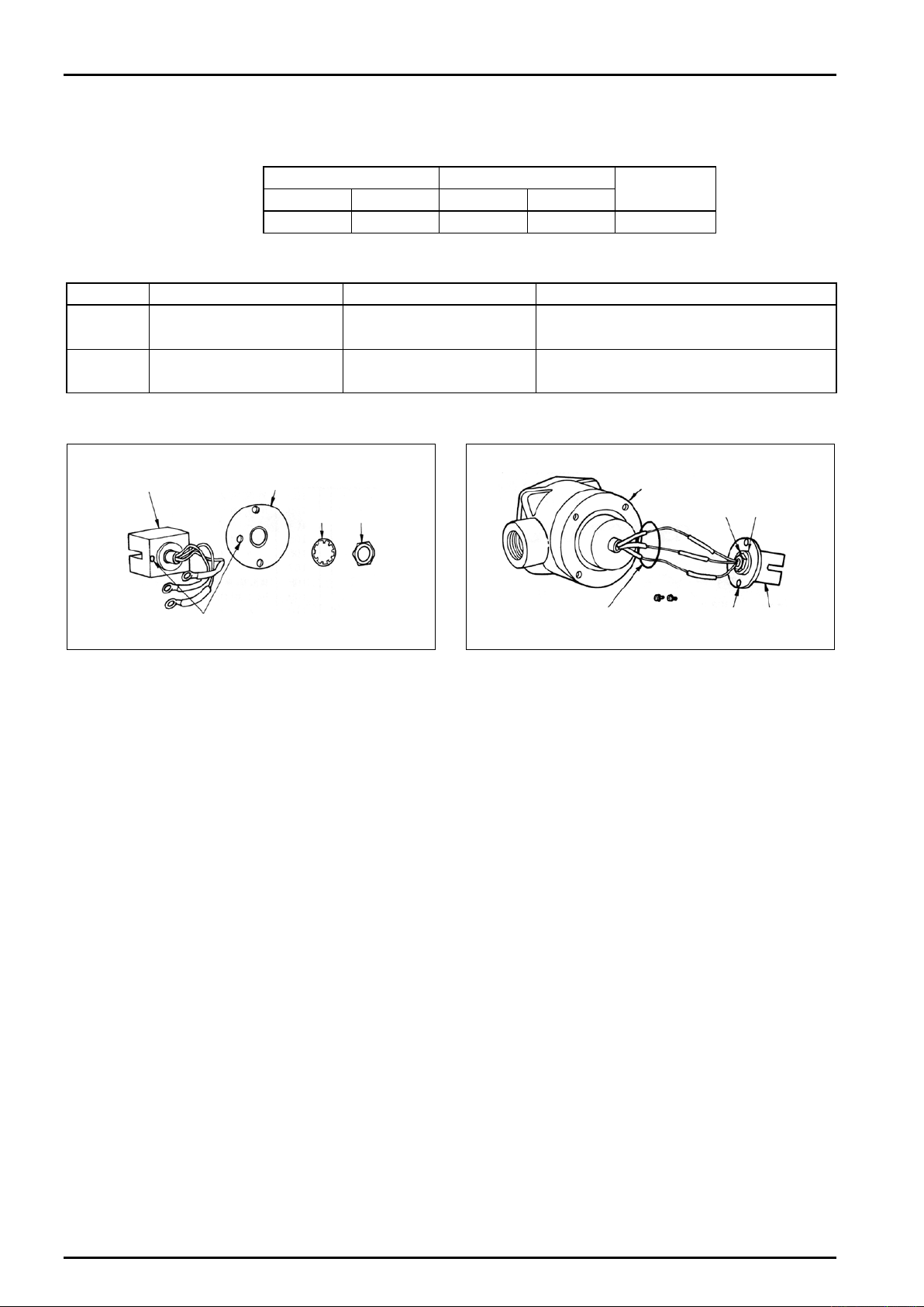
Noncontact Switch Unit Replacement
●
cst
/30℃ − 37.5℃
Gear Train Bearings
Spur Bevel Plain Ball
G2 G2 L3 L3 L3
Brake Shoe
Nisseki Launa 40
(Nippon Oil Co., Ltd.)
Jun BG Grease
(Nihon Tokushu-koyu Co., Ltd.)
PG30 PG30EP
Fig. 8
111
109
110
※
Terminal box
126
Fig. 9
117
116
118 115
108
※
1. Di s c o n n e c t wiring connections. Take off two
terminal fitting screws (106) and remove terminals
(104). The noncontact switch unit (108) can be
separated by taking off two additional screws (130).
2. Remove nu t (110) an d toothed was h er (109)
holdi n g the nonco n ta c t swi t c h uni t (10 8 ) to
mounting bracket (111), and remove the switch
unit. Install a new switch unit in alignment with
locating slot (marked ※ ). Ensure correct wiring
connections with due regard to color coded leads
(white, red and black).
1. Take off four bolts (329) and remove the casing
of pressure-resistant gasket (301) from housing
(101). Then, take off two screws (126) securing the
noncontact switch unit (115) in place and remove
the switch unit.
2. Unsolder wire lead connections (marked ※ ), take
off nut (117) and toothed washer (116) holding the
noncontact switch unit (115) to mounting bracket
(118), and separate the switch unit.
Replace with a new noncontact switch unit in the
same manner as described for PG30 pulse generator
and solder wire leads to their connections.
4
Page 5
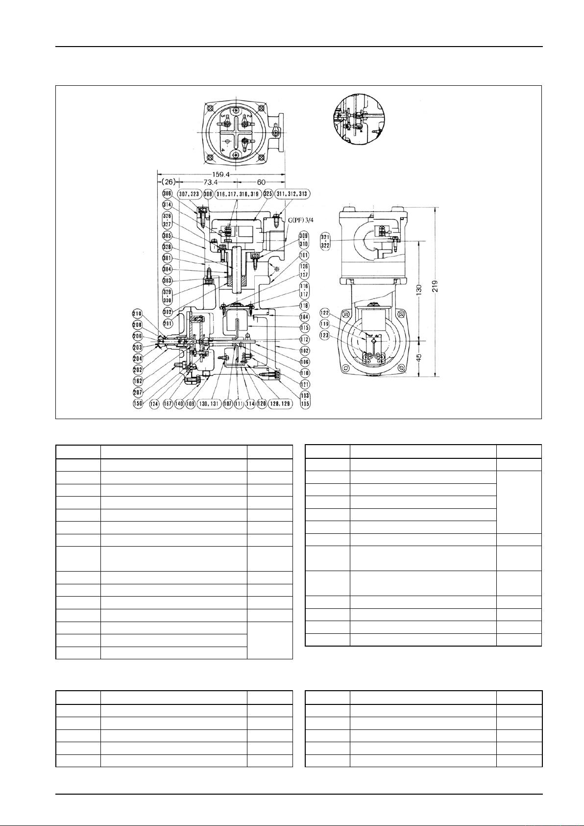
ASSEMBLY DRAWING AND PARTS LIST, PG30EP
■
T-518-11-E
Transmission gear engagement in the
transmission gear box shipped from our factory
before April, 1987, is as shown in the inset.
Pulse Generator Assembly
Sym.No. Part Name Q 'ty
101 Housing 1
102 Housing lid 1
103 Housing lid bolt (M3×15) 4
104 O-ring (JIS G70) 1
105 Washer, Housing lid (M5) 4
106 Shaft 1
107 Ball bearing (L-1040ZZ) 2
108
110 Setscrew (M3×4) 1
111 Toothed disk (with hub) 1
112 Thrust spacer 1
114 Holder 1
115 Detector (noncontact switch unit)
117 Nut, Detector
Blind plug (Rc(PT)1/8, hex. socket
head)
1set116 Toothed washer, Detector
}
Once disassembled, apply a liquid sealant
(Hermeseal # 723, or equivalent).
▲:Replacement parts
Sym.No. Part Name Q 'ty
118 Mounting bracket, Detector 1
119 Brake shoe
120 Plate
121 Shoe shaft
122 Spring
123 Clip ring
124 Thrust spacer 1
1
126
127
128 Plate fitting screw (M3×6) 2
129 Washer, Plate fitting screw (M3) 2
130 Holder fitting screw (M4×6) 2
131 Washer, Holder fitting screw (M4) 2
Fitting screw, Detector mounting
bracket (M4×8)
Washer, Detector mounting
bracket (M4)
▲
1set
}
2
2
Mounting Bracket Assembly
Sym.No. Part Name Q 'ty
201 Mounting bracket 1
202 Bearing 1
203 Transmission shaft 1
204 Bevel gear 1
205 Coupling 1
Sym.No. Part Name Q 'ty
206 Coupling retaining pin 2
207 Fitting bolt, Mounting bracket 4
208 Thrust seat 1
209 Gasket, Mounting bracket 1
210 Oil retaining bearing 2
5
Page 6

T-518-11-E
Transmission Gear Box
Sym.No. Part Name Q 'ty
150 Transmission Gear Box 1 set
162 Ball Bearing B (LF1260ZZ) 1
167
Fitting Screw, Transmission Gear
Box
NOTE: Shaded area in the drawing
Terminal Box Assembly
Sym.No. Part Name Q 'ty
301 Pressure-resistant packing casing 1
302 Pressure-resistant packing 1
303 Pressure-resistant packing washer 1
304 Pressure-resistant packing retainer 1
305 Terminal box housing 1
306 Terminal box housing lid 1
307
308 O-ring (JIS G70) 1
309
310 Washer (M5) 4
311 Ground terminal screw (M4×8) 2
312 Washer (M4) 2
313 Crimp terminal (φ4) 8
314 Terminal block 1
Fitting bolt, Terminal box housing
lid
Bolt, Terminal box housing
(M5 ×12)
A replacement transmission gear box is available as
an assembly. When ordering this box, please specify
the gear ratio (e.g., 1/10 or 1/1) stamped on its plate.
4
Sym.No. Part Name Q 'ty
315
316 Hex bolt for terminal (M4×18) 3
317 Washer (M4) 6
318 Washer (M4) 3
319 Nut (M4) 9
4
4
321
322 Washer (M4) 2
323
325 Wiring instruction label 1
326
327 Washer 4
328 Cabtyre cable 1
329
330 Washer (M5) 4
Flameproof enclosure rating
nameplate
Terminal block fitting screw
(M4×10)
Washer, Terminal box housing lid
(M5)
Pressure-resistant packing retaining bolt (M5×15)
Bolt, Pressure-resistant packing
casing (M5×12)
1
2
4
4
4
Ordering Instructions: Please supply us with the details of your order, which should include the owmeter
model, product No., Instruction manual No., symbol No., quantity desired, and part
name.
6
Page 7
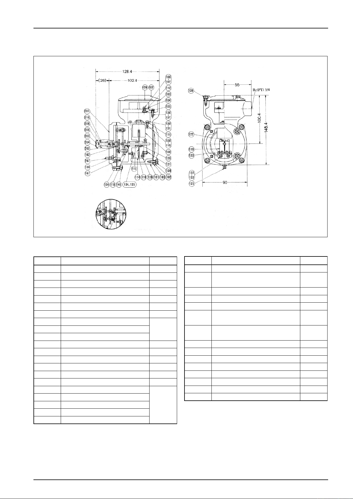
ASSEMBLY DRAWING AND PARTS LIST, MODEL PG30
■
Transmission gear box (150) and mounting bracket (200)
are also shared by PG30EP; see pages 5 and 6.
T-518-11-E
Transmission gear engagement in the transmission
gear box shipped from our factory before April,
1987, is shown in the inset.
Pulse Generator Assembly
Sym.No. Part Name Q 'ty
101 Housing 1
102 Housing lid 2
103 Gasket, Housing lid 2
104 Terminal 1
105 Nut, Terminal (M4) 3
106 Screw 3
107 Washer 3
108 Detector (noncontact switch unit)
1set109 Toothed washer, Detector
110 Nut, Detector
111 Mounting bracket, Detector 1
112 Crimp terminal 6
114 Holder 1
115 Shaft 1
116 Toothed disk (with hub) 1
118 Ball bearing (CF-1040ZZ) 2
119 Brake shoe
120 Plate
121 Shoe shaft
122 Spring
123 Clip ring
}
▲
1set
}
▲:Replacement parts
Sym.No. Part Name Q 'ty
124 Thrust spacer 1
125
126 Terminal identification label 1
127 Wiring instruction label 1
129 Toothed disk setscrew (M3×4) 1
130
131
132 Plate fitting screw (M3×6) 2
133 Washer, Plate fitting screw (M3) 2
134 Holder fitting screw (M3×6) 2
135 Washer, Holder fitting screw (M4) 2
136 Terminal fitting screw (M4×10) 2
137 Washer Terminal fitting screw (M4) 2
139 Housing lid bolt (M4×12) 8
140 Housing bolt (M5×12) 4
Blind plug
(PT1/8, hex socket head)
Fitting screw, Detector mounting
bracket (M4×8)
Washer, Detector mounting
bracket (M4)
1
2
2
7
Page 8

T-518-11-E
GENERAL SPECIFICATIONS
■
Item
Model PG32 PG33 PG32EP PG33EP
Output
pulses
Pulse generation HF generation and single pulse detection (3-wire system)
Certified explosionproof rating Standard Flameproof
Explosionproof rating d2G4
Cable entry Rc (PT) 3/4 female G (PF) 3/4 female
Operating temperature range − 20℃ to +80℃
Number of gear teeth (toothed disk) 25 pole
Pulse generator unit
Electrical specifications
System of
units
Power Source ※ 12VDC ±10%
Current drain 30mA max.
Output signal levels
Maximum operating frequency 2.5kHz (at sensing terminal)
Transmission length 1 kilometer max.
Output waveform Quasi rectangular wave ("0" / "1"= 35/65 to 60/40)
Hysteresis width 0.5mm min.
Pulses per
revolution
Reduction gear ratio 2/1 20/1 2/1 20/1
Type SHW - 1001
Color Green
Model
PG30 PG30EP
100 P/rev 1000 P/rev 100 P/rev 1000 P/rev
"0"= 0.5V max.
"1"= 6.2 to 7.6V (across 10kΩ resistive load)
※ Standard supplies (DC power supplies) are available from OVAL. You can use one if required.
8
Page 9
T-518-11-E
9
Page 10

T-518-11-E
All specifications are subject to change without notice for improvement.
10
2014.11 Revised
2009.12 Revised △
T-518-11-E(2)
 Loading...