

Oval MAG-OVAL III, MAG-OVAL III MGW, MAG-OVAL III MGS Instructions Manual
ER
R
.
ALM.
ER
R
.
ALM.
Electromagnetic flowmeter
Ins. No. C
−
102−1−E
Models MGW and MGS
Every MAG-OVAL III is manufactured under the stringent quality control and thoroughly tested and
inspected before shipment from our factory.
This manual is designed to assist the user to obtain the best performance of this product throughout
its service life. In order to take sufficient care, please read this instruction carefully before the use
and keep it handy for quick reference.
1

C−102-1-E
CONTENTS
1. GENERAL ............................................................................................................................4
2. BEFORE YOU BEGIN ..........................................................................................................5
3. PIPING INSTRUCTIONS .....................................................................................................6
3.1 Straight Pipe Section ..................................................................................................................................... 6
3.2 Keeping the Flow Tube Completely Filled ..................................................................................................... 6
3.3 Physical Orientation of the Probe .................................................................................................................. 7
3.4 Bypass Line ................................................................................................................................................... 7
3.5 Prevention of Negative Pressure ................................................................................................................... 8
3.6 Installation Location ....................................................................................................................................... 8
4. PROBE INSTALLATION ......................................................................................................8
4.1 Screw-in Type (nominal sizes 3 to 15mm) ..................................................................................................... 8
4.2 Wafer Type (nominal sizes 25 to 150mm) ...................................................................................................... 9
4.3 Transmitter Installation ................................................................................................................................. 10
5. GROUNDING .....................................................................................................................12
6. WIRING CONNECTIONS ..................................................................................................12
6.1 Power and Output Signal Wiring Connections ............................................................................................ 12
6.2 Wiring Connection Diagram ......................................................................................................................... 13
6.3 Power and Output Signal Terminal Identification......................................................................................... 13
6.4 Wiring Connection Instruction ..................................................................................................................... 14
7. START-UP ..........................................................................................................................15
8. MAINTENANCE .................................................................................................................15
9. TRANSMITTER DISPLAY AND OPERATION ...................................................................16
9.1 Explanation of Display ................................................................................................................................. 16
9.2 Operation Basics ......................................................................................................................................... 16
9.2.1 Setup Mode and Measure Mode .......................................................................................................... 16
9.2.2 Key Operations ..................................................................................................................................... 17
10. MEASURE MODE ...........................................................................................................18
10.1 Measure Mode Screen ............................................................................................................................... 18
10.2 Resetting Resettable Total ......................................................................................................................... 18
10.3 Error/Alarm and Status Display ................................................................................................................. 19
10.4 Screen Change for Instant and Total Flow Indication ................................................................................ 20
11. OPERATIONS IN SETUP MODE ....................................................................................21
11.1 Transition from Measure Mode to Setup Mode ......................................................................................... 21
11.2 Menu Operation in Setup Mode ................................................................................................................ 22
11.3 Changing Parameters ................................................................................................................................ 23
11.3.1 Parameter Setting in Selection System (Ex. Changing backlight setting) ........................................... 23
11.3.2 Setting Numeric Parameters (Ex. Changing flow range setting) ......................................................... 24
11.3.3 Viewing Exponential Indication ........................................................................................................... 25
12. DISPLAY TRANSITION ...................................................................................................26
12.1 Display Transition (1) Setting Display ...................................................................................................... 26
12.2 Display Transition (2) Setting Flow Parameter......................................................................................... 28
12.3 Display Transition (3) Setting Output Signal ............................................................................................ 30
12.4 Display Transition (4) Setting Error and Alarm Output............................................................................. 32
12.5 Display Transition (5) Setting Diagnosis and Maintenance Functions .................................................... 34
2

C−102-1-E
13. ANALOG OUTPUT FUNCTION ......................................................................................36
13.1 Setting Analog Output ............................................................................................................................... 36
13.2 Analog Output at Error/Alarm .................................................................................................................... 36
13.3 Adjusting Analog Output ............................................................................................................................ 37
14. PULSE OUTPUT AND TOTALIZING FUNCTION ...........................................................38
14.1 Setting Pulse Output .................................................................................................................................. 38
14.2 Pulse Output at Error/Alarm ....................................................................................................................... 39
15. STATUS OUTPUT FUNCTION ........................................................................................40
15.1 Selecting Status Output ............................................................................................................................. 40
15.2 High/Low Limit Alarm Function ................................................................................................................. 40
15.3 Flow Direction Output Function ................................................................................................................. 40
16. LOOP TEST (SIMULATIVE OUTPUT) FUNCTION .........................................................41
16.1 Simulative Output Operation ..................................................................................................................... 41
17. COMMUNICATION FUNCTION ......................................................................................42
17.1 Communication Specifications .................................................................................................................. 42
17.2 Setting Communication Functions ............................................................................................................ 43
18. SELF-DIAGNOSIS FUNCTION .......................................................................................44
18.1 Self-diagnosis Items .................................................................................................................................. 44
18.2 Diagnosing All Items .................................................................................................................................. 45
18.3 Diagnosing Self-diagnosis Items Individually ............................................................................................ 46
19. LCD CHECK ....................................................................................................................46
20. ERROR/ALARM STATUS LIST .......................................................................................47
20.1 Error/Alarm List .......................................................................................................................................... 47
20.2 Other Statuses ........................................................................................................................................... 48
21. PARAMETER LIST ..........................................................................................................49
22. GENERAL SPECIFICATIONS .........................................................................................50
23. FLOW RANGE .................................................................................................................51
24. PRODUCT CODE EXPLANATION ..................................................................................52
25. OUTLINE DIMENSIONS .................................................................................................53
This manual uses the precaution words "NOTE", "CAUTION", and "WARNING" as explained
below:
NOTE: Notes are separated from the general text to bring the user's attention to
important information.
CAUTION: Caution statements signal the user of hazards or unsafe practices which
could result in minor personal injury or product or property damage.
WARNING: Warning statements signal the user of hazards or unsafe practices
which could result in severe personal injury or death.
3
C−102-1-E
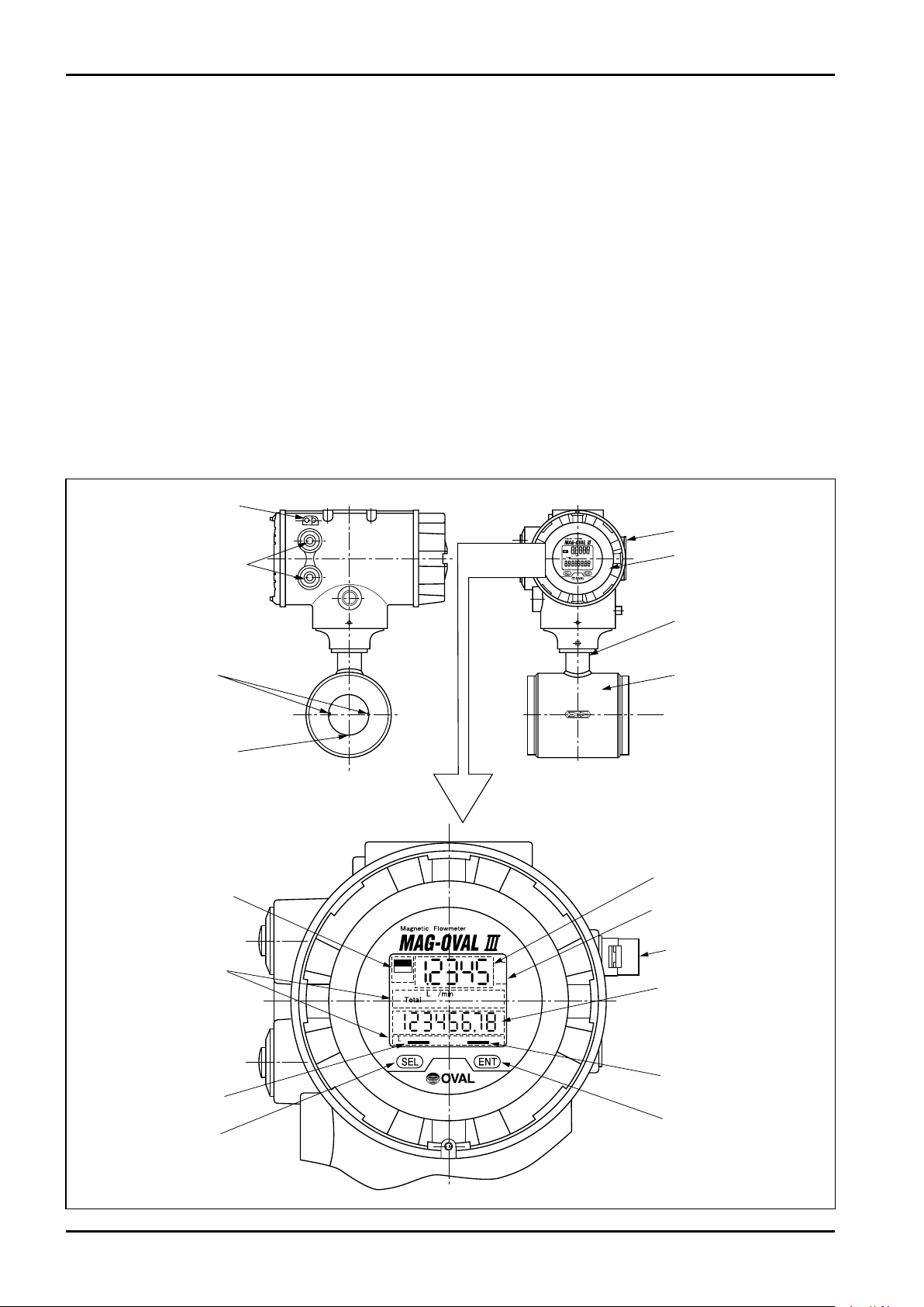
Electrodes
GND electrode
Cable entries
GND terminal
Transmitter
Adapter
Probe
Product nameplate
ERR.
ALM.
Alarm/Error
indicator
[ENT] key indicator
[SEL] key
indicator
[SEL] key
[ENT] key
Magnet
LCD Upper row
instant flow rate indicator
LCD bottom row
total flow indicator
Unit display
Unit display
1. GENERAL
Electromagnetic flowmeters operate on the basis of Faraday's law of electromagnetic induction. When a
conductive liquid flows through the magnetic field applied perpendicul ar to the direction of flow, an
electromotive force (EMF) is induced proportionally to the average velocity of flow according to Faraday's law. A
pair of electrodes located on the flow tube wall picks up the induced EMF which is then amplified in the
transmitter to determine the volumetric flow rate.
FEATURES
(1) Easy handling and low pressure loss contribute to low cost of installation and operation of the flowmeter,
providing excellent cost-effectiveness.
(2) Four kinds of electrodes are available for wetted area. Application to highly corrosive liquids is also
supported.
(3) In addition to magnet handling on the site, monitoring, various kinds of setting change, logging, loop test,
and self-diagnosis are available.
(4) Wide measuring range starting from zero.
■ Part names
4
C−102-1-E
①
②
③
④
⑤
⑥
⑦
⑧
⑨
⑩
⑪
⑫
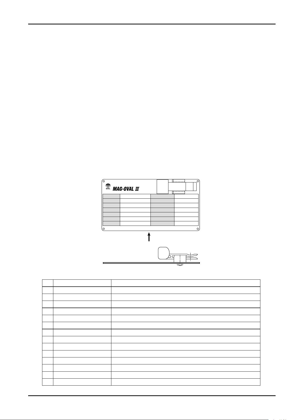
⑬
⑭
Magneti c F l ow m et e r
OVAL Corporation
MADEINJAPAN
MODEL
SERIALNo.
TAGNo.
FLUID
FLOWRANGE
MAX.PRESS
MAX.TEMP
ELECTRODE
POWER
DATE
ANALOGOUTPUT
PULSEOUTPUT
CAL.ZERO
CAL.FACTOR
A
Side view from Arrow A
2. BEFORE YOU BEGIN
Although this flowmeter is built and adjusted exactly to meet the customer specifications and, it is ready to
operate in your service by turning on the power, it is desirable for the operator to read this instruction manual
carefully for the best results in maintaining the stated accuracy and long life before initiating service operation.
You can avoid potential downtime of the equipment by observing the following instructions in particular.
(1) Confirm the operating conditions
The operating conditions and major specifications of this flowmeter appear on the nameplate attached to the
transmitter. Verify that the conditions indicated agree with your particular operating conditions. If you are to
make measurement of corrosive liquids in particular, make sure of the compatibility of electrode materials, etc.
(2) About grounding
An electromagnetic flowmeter requires earth grounding. See the Grounding Instruction on page 12 for proper
grounding.
(3) Use with the flow tube filled with liquid
An electromagnetic flowmeter requires its internal space to be completely filled with the process liquid.
Ensure of a fully filled flow tube during operation.
(4) About field wiring
For intercabling between the electromagnetic flowmeter and receiving instrument, see the section "Wiring
Connections".
Please remember to check terminal numbers for correct connections before operation.
〈Explanation of items shown on nameplate〉
No. Item Description
(1) Product code Ex. MGW1-0501T17E-10A
(2) Product No.
(3) Instrument No. As designated
(4) Fluid measured Ex. Water
(5) Flow range Ex. 0 to 100m3/h
(6) Max. pressure Allowable max. pressure of flowmeter
(7) Max. temperature Allowable max. temperature of flowmeter
(8) Electrode material Ex. SUS316L (depending on selected type)
(9) Power spec. Ex. 85 to 264VAC 50/60Hz (depending on selected type)
(10)
Month/Year of shipment
(11)
Analog output 4 to 20mA
(12)
Pulse output At factored pulse Ex. 1L/P, At frequency pulse Ex. 1000Hz at F.S.
(13)
Calibration zero value
(14)
Calibration factor value
——
——
——
——
5
C−102-1-E
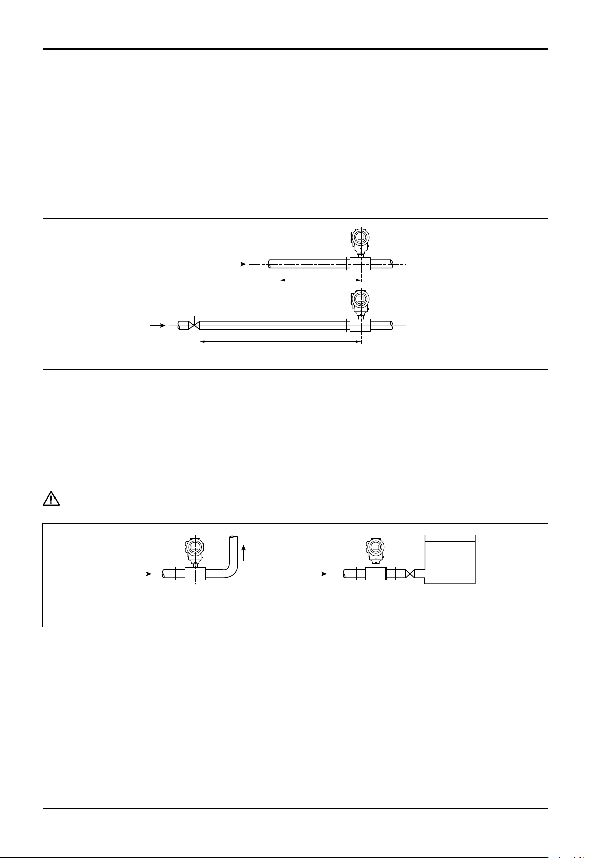
Flow
5D min.
Probe
Flow
Partially open valve
10D min.
Probe
(1)
(2)
D: Nominal pipe diameter
Flow
Flow
Probe Probe
Tank
(A) (B)
3. PIPING INSTRUCTIONS
3.1 Straight Pipe Section
(1) Provide at least 5D (D: nominal pipe diameter) of straight piping upstream of the meter. For screw-in type
meters (3 to 15 mm in nominal diameter), no straight piping is required because of their long face-to-face
dimension with respect to their diameter.
(2) It is preferable that partially open valves or other devices that disturb the flow velocity pattern to be located
downstream of the meter. If such devices are desired to be placed upstream of the meter for some reason,
provide at least 10D of straight pipe section upstream of the probe.
Fig. 3.1 Standard Straight Pipes
3.2 Keeping the Flow Tube Completely Filled
(1) It is essential that the electromagnetic flowmeter be installed in a pipeline completely filled with the process
fluid.
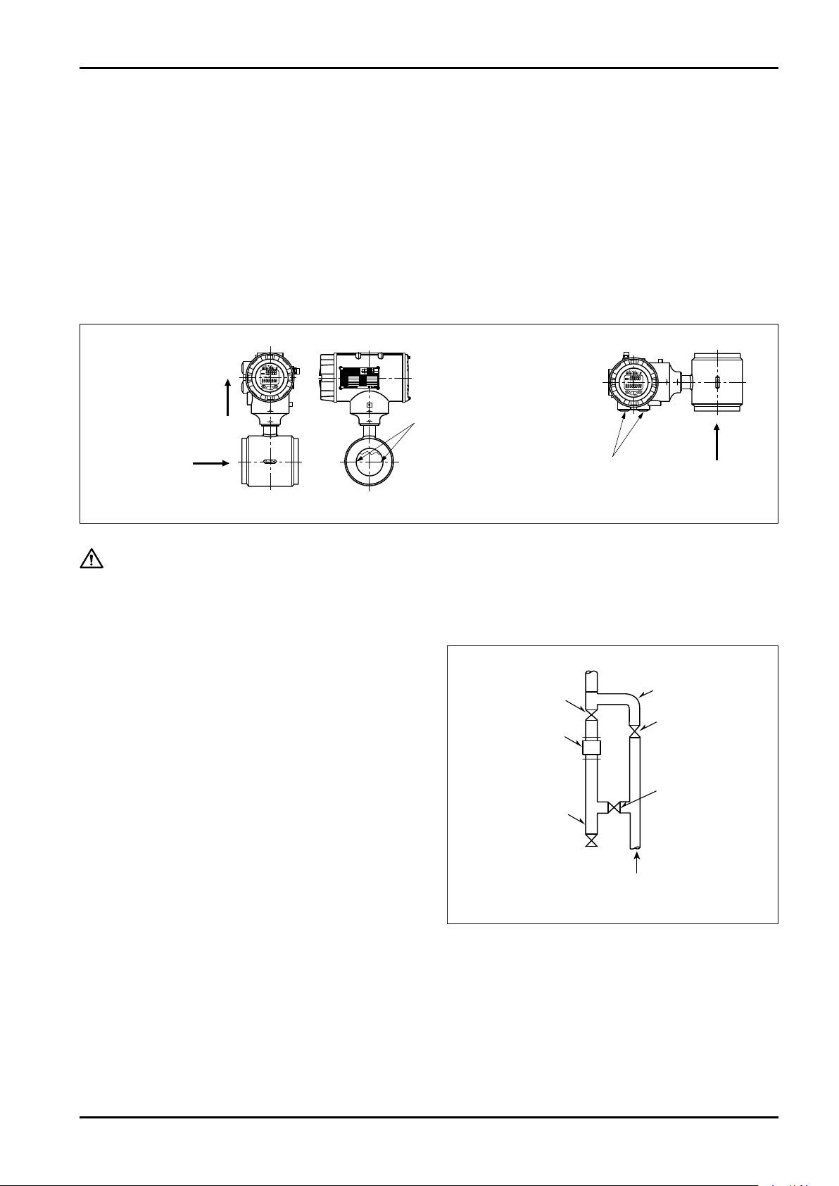
(2) In cases of horizontal installation or vertical installation where the fluid flows top to bottom, we recommend
providing a rising pipe or maintaining sufficiently large hydraulic head downstream, for these piping
arrangements are likely to create empty or partially filled conditions. (See Figure 3.2)
CAUTION: False output pulses may be produced if the flow tube is not filled completely
with fluid.
Fig. 3.2 Proper Examples of Downstream Piping
6
C−102-1-E
Electrodes
FLOW
FLOW
Horizontal run
Transmitter up with
axis of electrodes
horizontal
Vertical run
Cable entries pointing
downward
Bottom → Top
flow direction
is preferable.
Cable entries
(face down)
UP
Probe
Blow pipe
Downstream
valve
Bypass
Upstream
valve
Vertical flow direction
Valve
3.3 Physical Orientation of the Probe
The probe may be installed in any physical orientation as long as the flow tube is completely filled with the
process fluid.
Keep in mind the following precautions, however.
(1) Horizontal run
In a horizontal line, keep electrodes axes on a level plane to minimize the risk of electrodes being insulated
momentarily due to suspended gas bubbles.
(2) Vertical run
In a vertical line, avoid a transmitter orientation with cable entry pointing upward to prevent rainwater from
entering the transmitter.
Fig. 3.3
CAUTION: With liquids that contain suspended solids or liquids that can separate easily, a
vertical run is suggested to reduce the possibility of solids deposition, wear and
separation to a minimum.
3.4 Bypass Line
We recommend to provide a bypass line to facilitate
maintenance and inspection.
Particularly in a vertical run, it is desirable that the
piping be arranged to facilitate removal of solids
build-up inside the pipe line.
Fig. 3.4 Vertical Piping Example
7

C−102-1-E
Flow
Probe
Flow control valve
Probe
Lining
Seal face
(A) (B)
Gasket
(Must be in place.)
Do not seal on threads.
Flow
Upstream valve
Probe
Negative press. relief valve
Downstream valve
3.5 Prevention of Negative Pressure
In order to maintain a long-term service life of the
pro be, take pos i t ive measu res to elimi n ate
circumstances that can create negative pressure
in the pipeline.
(1) If b oth upstream a nd do wnst ream val ves
remain closed with fluid temperature higher
than that of the atmosphere, fluid contraction
may ta ke place as the fluid co ols down ,
creating negative pressure in the enclosed
space of pipeline. You can solve this problem
by providing a negative pressure relief valve
near the probe.
(2) If a vertical piping continues downstream of
the probe:
While stopping or adjusting the fluid flow with
the upstream valve of flowmeter, negative
pressure can be created in the pipeline. To
prevent this condition, stop or adjust the fluid
flow with the downstream valve.
Fig. 3.5 Piping Example to Prevent Negative Pressure (1)
Fig. 3.6 Piping Example to Prevent Negative Pressure (2)
3.6 Installation Location
Avoid locations such as:
(1) Near motors, transformers, or heavy electrical equipment
(2) Inaccessible for maintenance and inspection
(3) Temperature varies widely or vibration is excessive
(4) Potential risk of submergence
4. PROBE INSTALLATION
4.1 Screw-in Type (nominal sizes 3 to 15mm)
(1) Process connection is of screw-in type. By using dedicated unions, be sure to seal the end face of probe
(lining surface). Never apply a seal to threads as it is likely to cause unexpected trouble.
8
Fig. 4.1
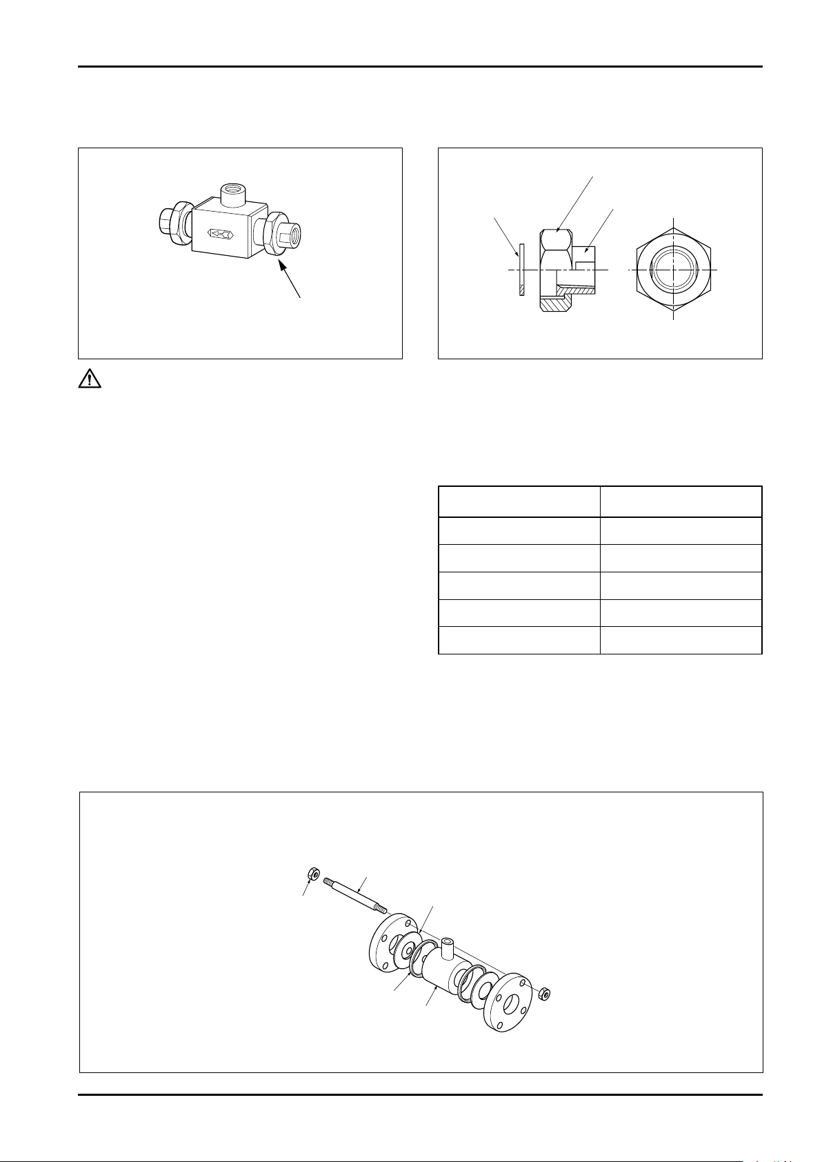
(2) Union and other joints should be of dedicated accessories furnished for connecting pipes.
Union fitting
Tightening nut
Gasket
Rc (PT) screw adapter
Hex nut
Connecting bolt
Flange gasket
Adjust ring
Probe
Use of nonstandard fittings can lead to unexpected trouble.
Fig. 4.2 Example of Unions Installed in Place Fig. 4.3 Union Fitting (accessory for piping)
CAUTION: Install the transmitter securely.
4.2 Wafer Type (nominal sizes 25 to 150mm)
C−102-1-E
Install the meter observing the following precautions:
Flange Tightening Torque Specifications
(1) Protection of probe's linings
a. Exercise care to avoid damage to the linings of
probe.
Nominal size (mm) Torque (N・m)
25, 40 39 to 54
b. Do not fail to use flange gaskets when making
pipe connections.
c. Tighten connecting bolts carefully to avoid
uneven tightening or over tightening.
( R efe r to th e f l an g e ti g ht e ni n g to r qu e
specifications in the table on the right.)
50 70
80 54
100 78
150 125
(2) Maintaining accuracy
a. To ensure concentric alignment of the probe,
do not fail to use the adjust rings furnished (or
adjust collars for nominal size 150mm meter
with JIS 10K flange rating).
b. Exercise care not to let flange gaskets protrude
inside the pipe.
◆ Installing adjust rings ◆ Nominal sizes 25mm to 150mm
(For nominal size of 150mm with flange rating of JIS 10K, see figure 4.5 on the next page.)
Fig. 4.4
9
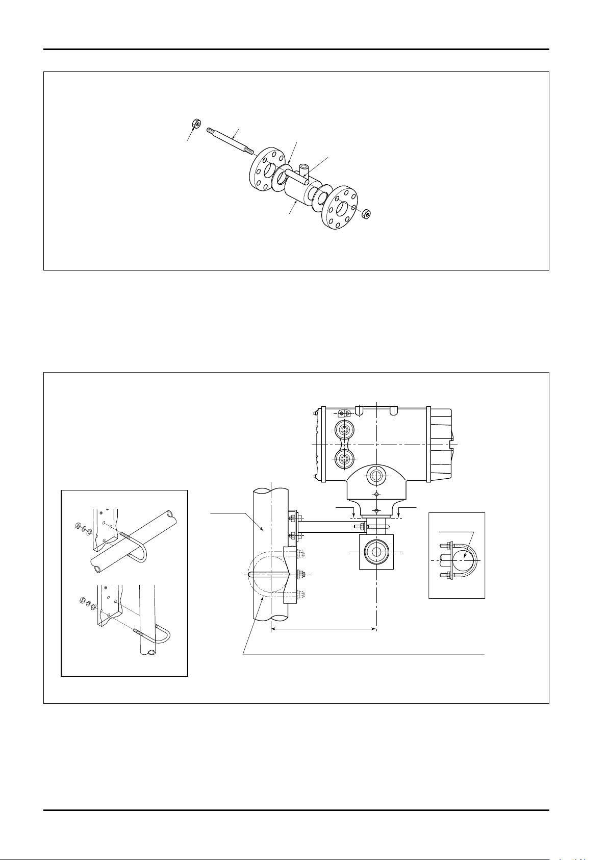
C−102-1-E
Hex nut
Connecting bolt
Flange gasket
Adjust collar
(Install four adjust collars
uniformly 90° apart.)
Probe
Installation on a horizontal pipe is shown with dotted lines.
2″ Pipe
Adapter
Sec A-A
181.6
A A
◆ Installing adjust collars ◆ Nominal size 150mm, flange rating JIS 10K
Fig. 4.5
4.3 Transmitter Installation
(1) Securing the integral transmitter (nominal size 3 to 6mm):
For the screw-in type (nominal size 3 to 6mm), tubes are too thin to support the meter.
Therefore, secure the transmitter in the manner shown in the figure below.
Using the U-bolt and mounting bracket
supplied with the flowmeter, fix the
flowmeter to a horizontal or vertical pipe
with nominal diameter of 2″.
* Pipe is not supplied with the flowmeter.
Mounting to a horizontal pipe
Mounting to a vertical pipe
Fig. 4.6 MAG-OVAL III Transmitter Hold-down Hardware
10
C−102-1-E
Display cover
Hex key (M4)
Display cover
A flat tool that
does not damage
the finish
Turn
Fitting screw (M3)
Display unit
Display unit
Pull
Connector pins
Display unit
Connector
socket
Display unit
Press along
the guide
Guide hole
Guide pin
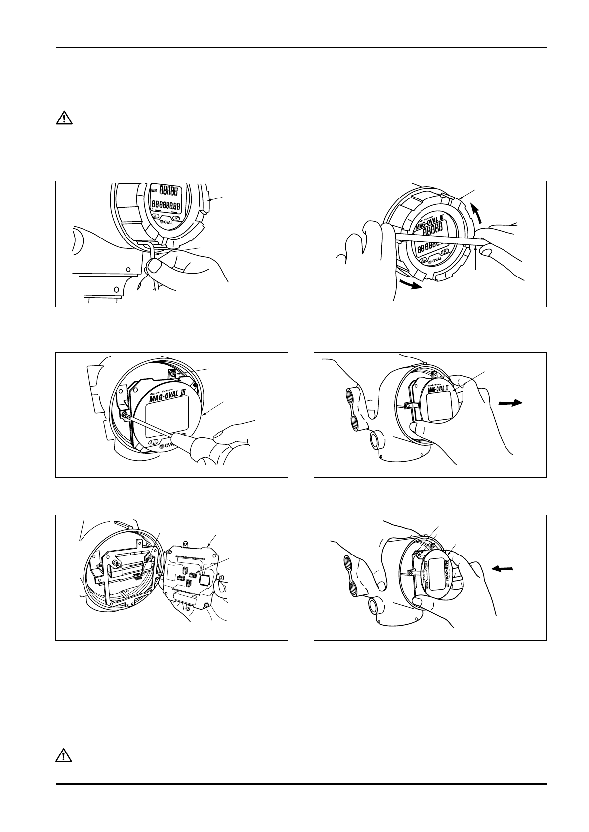
(2) Procedure to tilt the LCD display to the desired angle:
The display unit in its housing is rotatable in increments of 90 degrees through 360 degrees.
By changing the LCD display orientation, you can achieve optimum viewability also in a vertical line.
CAUTION: Do not forget to turn off the power before beginning this procedure. Another
precaution to remember is to eliminate static charges from the operator's body.
◆ Procedure to adjust angular orientation of display ◆
Fig. 4.7
(1) Using hex wrench, loosen the locking setscrew
(M4) securing the display cover in the locked
position.
Fig. 4.9
(3) Remove the mounting screws (4 places) with a
phillips screwdriver and detach the display unit.
Fig. 4.8
(2) Using a flat tool, loosen the display cover by
carefully turning it counterclockwise and hand
rotate it further until the cover comes off.
Fig. 4.10
(4) By pulling the display unit toward you, remove it.
Fig. 4.11
(5) The display unit is rotatable in 90° steps. Confirm
the locations of connector pins on the transmitter
body and mating sockets on the display unit.
(6) At the desired physical orientation of display unit,
rotatable in 90° steps, align four guide pins of the
unit with two mating guide holes and install into
Fig. 4.12
place by pressing it in a direction perpendicular
to its mating surface.
After determining the angular orientation of display unit, install display unit fitting screws, display cover, and
setscrew to lock the cover. Now the orientation adjustment is complete.
CAUTION: Install the display cover to the housing securely by tightening with a flat tool,
ensuring that no gap exists before tightening the locking setscrew.
11
C−102-1-E
Terminal block
cover
Terminal block cover
Turn
A flat tool that does
not damage the finish
GND terminal
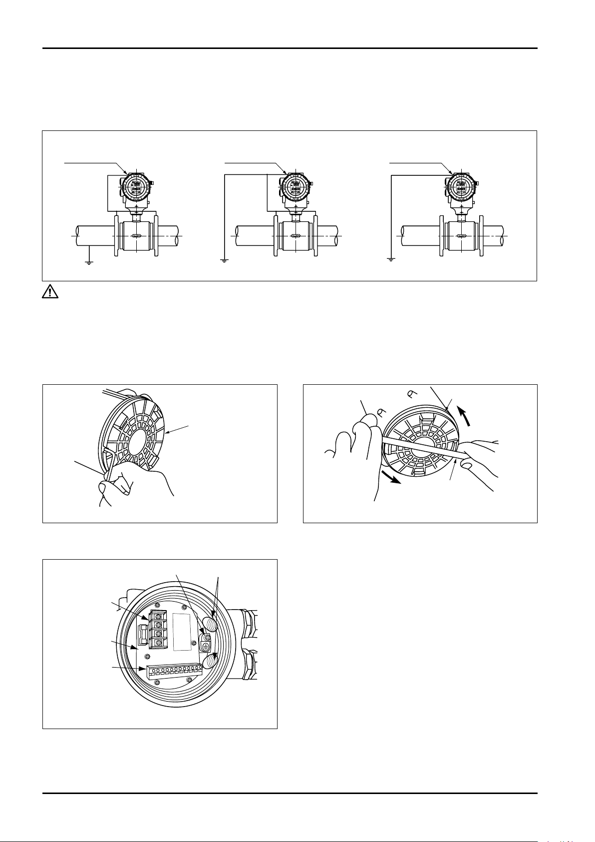
Probe
Metal
pipe
GND terminal
Probe
Metal
pipe
GND terminal
Probe
Resin
pipe
Internal ground terminal
Power terminal
block
Terminal board
Output signal
terminal block
Cable entries
5. GROUNDING
The electromotive force detected across electrodes of the probe is a very weak voltage measured against the
reference potential of metered liquid. Accordingly, earth grounding (better than Class C grounding) is essential to
maintain the probe and metered liquid at the same potential. Illustrated below are the proper grounding procedures.
Grounded metal pipeline
Ungrounded metal pipeline Plastic or lined pipeline
Fig. 5.1
CAUTION: Do not connect to earth ground of heavy electrical equipment.
Connect the ground wire for the transmitter to external ground terminal or internal
ground terminal.
6. WIRING CONNECTIONS
6.1 Power and Output Signal Wiring Connections
Terminals for wiring connections are found at the back of transmitter housing. Remove the cover and make wiring connections.
(1) Using hex wrench, loosen the locking setscrew
(3) Separating the cover provides access to the
12
Fig. 6.1
(M4 hex socket head) securing the cover.
Fig. 6.3 Terminal Board
terminal board with cable entrance openings,
int ernal ear t h grou nd termi nal and ter minal
blocks for power and output signals.
Fig.6.2 Terminal Block Cover Removal
(2) Using a flat tool, carefully loosen the terminal
cover by rotating it counterclockwise and turning
further by hand until it comes off.
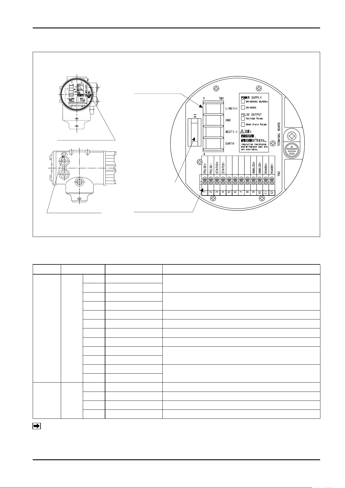
6.2 Wiring Connection Diagram
Power fuse
Output signal terminal (TB2)
screwless terminal
Internal ground terminal
External ground terminal
Power terminal (TB1)
screw size: M4
GND terminal location Details of terminal block
C−102-1-E
Fig. 6.4 Connecting Terminal Layout
6.3 Power and Output Signal Terminal Identification
Item Terminal No. Label Description
1 PULSE +
2 PULSE −
3 STATUS +
4 STATUS −
5 Unused
6 Unused
7 Unused
8 Unused
9 ANALOG +
10 ANALOG −
11 RS485 +
12 RS485 −
1 LINE(+) Power (with DC power: + )
2 GND Ground
3 NEUT(−) Power (with DC power: - )
4 EARTH Ground
Output signal
Power
TB2
TB1
Pulse output
(Open drain pulse output, or voltage pulse output)
Status output
(Open collector output)
Analog output
RS-485 communication
Note: Ground terminal "EARTH" shall be used for grounding. Ground terminal "EARTH" of this
flowmeter is internally connected to "GND".
13
C−102-1-E
ANALOG+
ANALOG-
R
R
R
STATUS+
STATUS -
Receiver
Receiver Receiver
Receiver
ON
PULSE+
PULSE-
PULSE-
E:18V
R
E
ON
PULSE+
30VDC
50mA Max.
30VDC
50mA Max.
Line
capacity C
Line
capacity C
R 2.2kΩ
510Ω Max.
6.4 Wiring Connection Instruction
The screw size for cable entry is G1/2.
For connections to terminals, use the following crimping terminals.
Terminal name Recommended crimping terminal
Power terminal Round crimping terminal for M4
Output signal terminal
(Screwless terminal block)
No crimping terminal is required.
Use a cable of 0.2 to 1.25mm2.
Standard wire strip length: 11mm
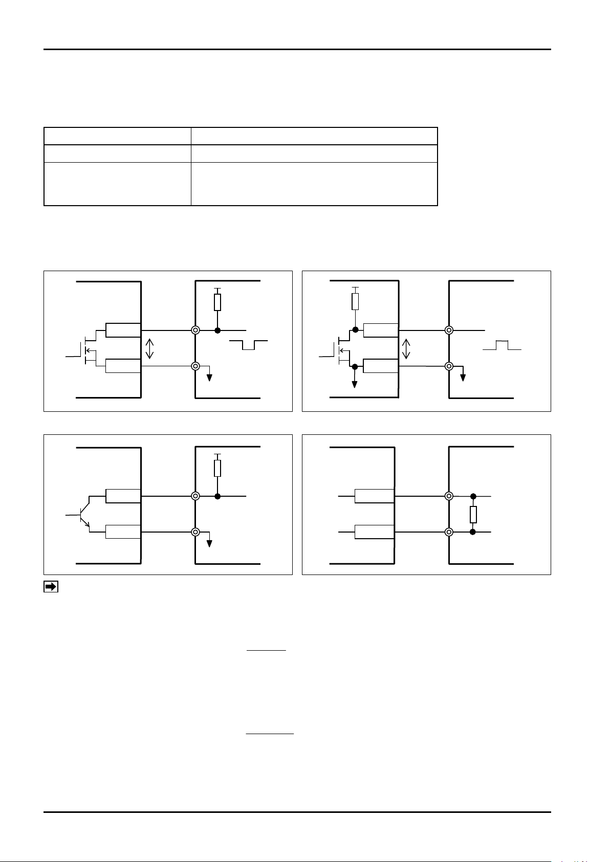
■ Connection to receiver
Open drain pulse output Voltage pulse output
Status output Analog output
0.1
R X C
NOTE: The tran smission len gth of pulse output is restricted by the outpu t frequency or receiver
specifications.
When setting open drain pulse
The pulse output waveform is attenuated by resistance R and line capacity C of the receiver.
The output frequency shall be set to F [Hz] < .
Line capacity C shall be set to 0.1μF/km.
When setting voltage pulse
The pulse output waveform is attenuated by resistance R and line capacity C in the flowmeter.
(The resistance factor of R is included in the following coefficient.)
The output frequency shall be set to F [Hz] < .
0.1
4400 X C
Line capacity C shall be set to 0.1μF/km.
14

C−102-1-E
7. START-UP
(1) Upon completion of meter installation and field wiring connections, reaffirm the following:
a. Is the meter correctly installed? Is the flow direction correct?
b. Is the flow tube completely filled with the fluid?
c. Is the grounding correctly done?
(2) After filling the flow tube with the fluid, turn the power on.
a. On power-up, allow at least a 30 minute warm-up period.
b. When fluid flows, a signal (pulse and analog) proportionate to the flow is output and instantaneous flow
rate (default) is displayed on the top row of the LCD of the transmitter and accumulated total flow or
resettable total flow is displayed on the bottom row of the LCD. (The display can be selected by setting.)
(3) Using the two magnet switches in the transmitter, you can confirm or change parameters, such as full scale
and pulse units, and change the LCD display menus.
8. MAINTENANCE
Every MAG-OVAL III leaves the factory under stringent quality control. As long as it is placed under proper
conditions, it will perform satisfactorily over long periods of time. If trouble arises, diagnose the nature of trouble
according to the troubleshooting chart below for the possible solution.
When error alarm is being generated, check the detail of error in accordance with "20. ERROR/ALARM STATUS
LIST".
Problems
No Output
Unstable Zero
Unstable Output
○
○
○
○
○
○ ○
○ ○ ○ ○
○ ○ ○
○ ○ ○
○ ○ ○
○ ○ ○
○ ○
○ ○
○ ○
○ ○
○
○
Quick Troubleshooting
Confirm
Large Meter Error
(1) The wiring is correct.
(2) The power is sufficiently supplied.
(3) The fuse is not interrupted.
(4) The fluid is flowing, or valves are open.
(5) Receiving instrument specifications are matching. (Input pulse width, etc.)
(6) There is no leak from pipeline connections and valves.
(7) Earth ground is properly completed.
(8) Flow tube is completely filled. (There is no bubble entrapment.)
(9) There are no pulsations in the flow.
(10) Motors, transformers, or other heavy electrical equipment are not near the probe.
(11) Lining (electrodes) is free from slurry deposits.
(12) Fluid conductivity is uniform.
(13) Fluid is free from magnetic slurries.
(14) Piping conditions are correct. (Inaccurate probe centering or insufficient upstream pipe length)
(15) Full scale (flow range) is correct.
(16) Calibration factor and zeroing const. are correct.
(17) Primary standard against which the meter is compared is correct.
15
C−102-1-E
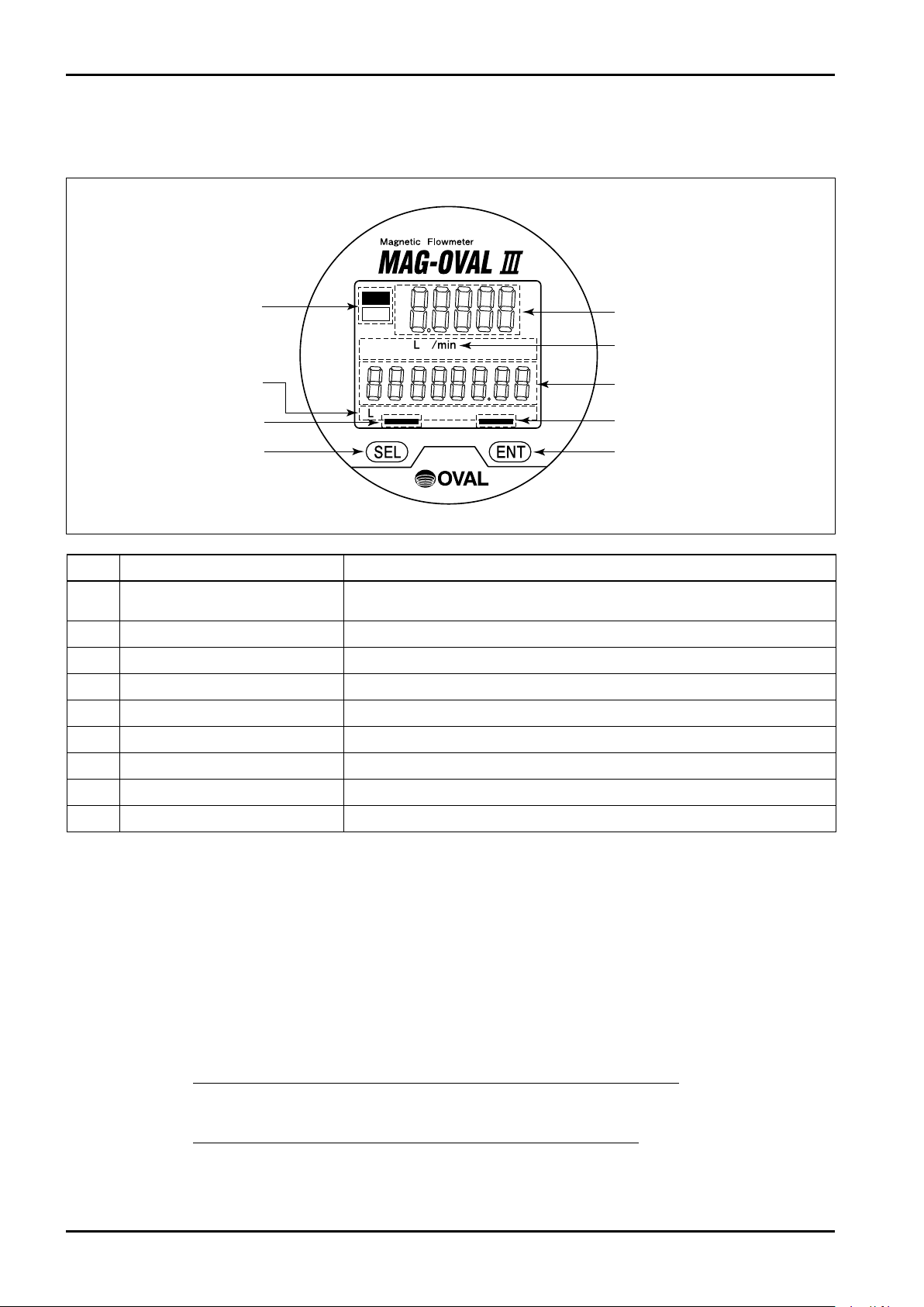
ALM
(5) Error/Alarm indicator
(4) Total flow rate unit
display
(8) [SEL] key indicator
(9) [SEL] key
(1) Instant flow rate display
(Top row)
(2) Instant flow rate unit
(3) Total flow display
(Bottom row)
(6) [ENT] key indicator
(7) [ENT] key
ERR
9. TRANSMITTER DISPLAY AND OPERATION
9.1 Explanation of Display
No. Item Description
Instant flow rate display (Top row)
(1)
Instant flow rate unit display Displays unit of instant flow rate.
(2)
Total flow display (Bottom row) Displays total flow or resettable total.
(3)
Total flow rate unit display Displays the unit of total flow.
(4)
Error/Alarm indicator Indicates the occurrence of error or alarm.
(5)
[ENT] key indicator Turns on when [ENT] key is operated.
(6)
[ENT] key [ENT] key. Operated by the use of attached selector magnet.
(7)
[SEL] key indicator Turns on when [SEL] key is operated.
(8)
[SEL] key [SEL] key. Operated by the use of attached selector magnet.
(9)
9.2 Operation Basics
9.2.1 Setup Mode and Measure Mode
This flowmeter is provided with two modes: "Measure mode" and "Setup mode".
"Measure mode" : The state after power on or at the completion of the Setup mode in item 11.
Displays instant flow rate and total flow.
The content of display can be changed by key operation.
After power on or at the completion of the Setup mode in item 11, the flowmeter returns to
→ Refer to "10.4 Screen Change for Instant and Total Flow Indication".
"Setup mode" : Checking and changing parameters and self-diagnosis are available from the Menu.
→ Refer to "11.1 Transition from Measure mode to Setup mode".
this state automatically.
Displays the instant flow rate. % flow rate and flow velocity can be selected
by switching.
16
C−102-1-E
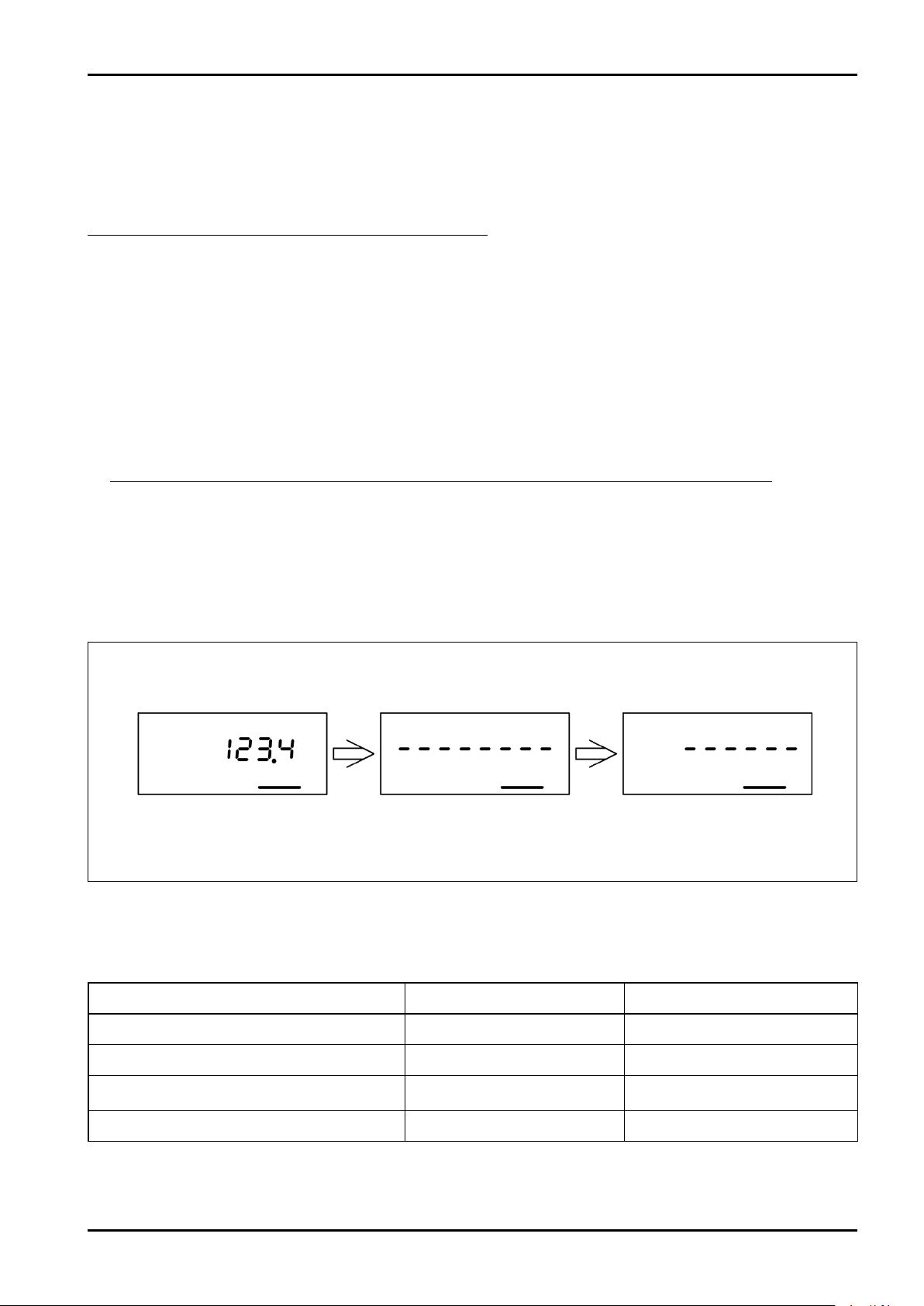
Ex. Indication when ENT key is set to ON
Indicator ON
Bar indication appears
on the bottom row display
Bars disappear
When all bars disappear,
press and hold ENT key
9.2.2 Key Operations
The keys of this flowmeter can be operated by placing the supplied magnet close to the "SEL" key and "ENT"
key in the magnet switch section.
Moving the magnet close to the SEL key or ENT key causes the magnet sensor to respond and the key entry is
set to ON.
The magnet sensor can respond through the glass screen.
■ Displayed messages during operation
Key operations include Ordinary depression (short key entry) and prolonged depression (press and hold key
entry).
(1) Ordinary depression
When the SEL key or ENT key is set to ON, the key indicator turns on. Setting the key entry OFF immediately
after the indicator turns on, starts ordinary operation.
If the key entry is kept ON, bars "- - - - - - -" appear on the bottom row display and then bars begin to
disappear at given time intervals.
If you set the key entry to OFF before the last bar disappears, it stays at the ordinary depression.
(2) Prolonged depression
Pressing and holding the SEL key or ENT key causes bars "- - - - - - -" to be displayed at the bottom row
display and then bars disappear one by one from the left.
Keeping the key ON until all bars disappear will start the prolonged depression.
(If you set the key to OFF before all bars disappear, it goes back to the ordinary operation (1).)
■ Description of each key operation
Each key operation executes the operation shown in the following table.
Key operation During Measure mode During Setup mode
SEL ((1) Ordinary depression) Changes display menu Switches operation, changes value
Press and hold SEL ((2) Prolonged depression)
ENT ((1) Ordinary depression)
Press and hold ENT ((2) Prolonged depression) Fixes the changes Fixes the changes
—
Switches between top and
bottom row displays
Return, Cancel
Shifts digits at the change of value
17
 Loading...