

Page 1
ER
R
.
ALM.
ER
R
.
ALM.
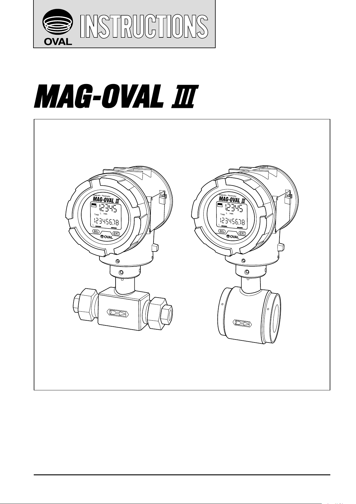
Electromagnetic flowmeter
Ins. No. C
−
102−1−E
Models MGW and MGS
Every MAG-OVAL III is manufactured under the stringent quality control and thoroughly tested and
inspected before shipment from our factory.
This manual is designed to assist the user to obtain the best performance of this product throughout
its service life. In order to take sufficient care, please read this instruction carefully before the use
and keep it handy for quick reference.
1
Page 2

C−102-1-E
CONTENTS
1. GENERAL ............................................................................................................................4
2. BEFORE YOU BEGIN ..........................................................................................................5
3. PIPING INSTRUCTIONS .....................................................................................................6
3.1 Straight Pipe Section ..................................................................................................................................... 6
3.2 Keeping the Flow Tube Completely Filled ..................................................................................................... 6
3.3 Physical Orientation of the Probe .................................................................................................................. 7
3.4 Bypass Line ................................................................................................................................................... 7
3.5 Prevention of Negative Pressure ................................................................................................................... 8
3.6 Installation Location ....................................................................................................................................... 8
4. PROBE INSTALLATION ......................................................................................................8
4.1 Screw-in Type (nominal sizes 3 to 15mm) ..................................................................................................... 8
4.2 Wafer Type (nominal sizes 25 to 150mm) ...................................................................................................... 9
4.3 Transmitter Installation ................................................................................................................................. 10
5. GROUNDING .....................................................................................................................12
6. WIRING CONNECTIONS ..................................................................................................12
6.1 Power and Output Signal Wiring Connections ............................................................................................ 12
6.2 Wiring Connection Diagram ......................................................................................................................... 13
6.3 Power and Output Signal Terminal Identification......................................................................................... 13
6.4 Wiring Connection Instruction ..................................................................................................................... 14
7. START-UP ..........................................................................................................................15
8. MAINTENANCE .................................................................................................................15
9. TRANSMITTER DISPLAY AND OPERATION ...................................................................16
9.1 Explanation of Display ................................................................................................................................. 16
9.2 Operation Basics ......................................................................................................................................... 16
9.2.1 Setup Mode and Measure Mode .......................................................................................................... 16
9.2.2 Key Operations ..................................................................................................................................... 17
10. MEASURE MODE ...........................................................................................................18
10.1 Measure Mode Screen ............................................................................................................................... 18
10.2 Resetting Resettable Total ......................................................................................................................... 18
10.3 Error/Alarm and Status Display ................................................................................................................. 19
10.4 Screen Change for Instant and Total Flow Indication ................................................................................ 20
11. OPERATIONS IN SETUP MODE ....................................................................................21
11.1 Transition from Measure Mode to Setup Mode ......................................................................................... 21
11.2 Menu Operation in Setup Mode ................................................................................................................ 22
11.3 Changing Parameters ................................................................................................................................ 23
11.3.1 Parameter Setting in Selection System (Ex. Changing backlight setting) ........................................... 23
11.3.2 Setting Numeric Parameters (Ex. Changing flow range setting) ......................................................... 24
11.3.3 Viewing Exponential Indication ........................................................................................................... 25
12. DISPLAY TRANSITION ...................................................................................................26
12.1 Display Transition (1) Setting Display ...................................................................................................... 26
12.2 Display Transition (2) Setting Flow Parameter......................................................................................... 28
12.3 Display Transition (3) Setting Output Signal ............................................................................................ 30
12.4 Display Transition (4) Setting Error and Alarm Output............................................................................. 32
12.5 Display Transition (5) Setting Diagnosis and Maintenance Functions .................................................... 34
2
Page 3
C−102-1-E
13. ANALOG OUTPUT FUNCTION ......................................................................................36
13.1 Setting Analog Output ............................................................................................................................... 36
13.2 Analog Output at Error/Alarm .................................................................................................................... 36
13.3 Adjusting Analog Output ............................................................................................................................ 37
14. PULSE OUTPUT AND TOTALIZING FUNCTION ...........................................................38
14.1 Setting Pulse Output .................................................................................................................................. 38
14.2 Pulse Output at Error/Alarm ....................................................................................................................... 39
15. STATUS OUTPUT FUNCTION ........................................................................................40
15.1 Selecting Status Output ............................................................................................................................. 40
15.2 High/Low Limit Alarm Function ................................................................................................................. 40
15.3 Flow Direction Output Function ................................................................................................................. 40
16. LOOP TEST (SIMULATIVE OUTPUT) FUNCTION .........................................................41
16.1 Simulative Output Operation ..................................................................................................................... 41
17. COMMUNICATION FUNCTION ......................................................................................42
17.1 Communication Specifications .................................................................................................................. 42
17.2 Setting Communication Functions ............................................................................................................ 43
18. SELF-DIAGNOSIS FUNCTION .......................................................................................44
18.1 Self-diagnosis Items .................................................................................................................................. 44
18.2 Diagnosing All Items .................................................................................................................................. 45
18.3 Diagnosing Self-diagnosis Items Individually ............................................................................................ 46
19. LCD CHECK ....................................................................................................................46
20. ERROR/ALARM STATUS LIST .......................................................................................47
20.1 Error/Alarm List .......................................................................................................................................... 47
20.2 Other Statuses ........................................................................................................................................... 48
21. PARAMETER LIST ..........................................................................................................49
22. GENERAL SPECIFICATIONS .........................................................................................50
23. FLOW RANGE .................................................................................................................51
24. PRODUCT CODE EXPLANATION ..................................................................................52
25. OUTLINE DIMENSIONS .................................................................................................53
This manual uses the precaution words "NOTE", "CAUTION", and "WARNING" as explained
below:
NOTE: Notes are separated from the general text to bring the user's attention to
important information.
CAUTION: Caution statements signal the user of hazards or unsafe practices which
could result in minor personal injury or product or property damage.
WARNING: Warning statements signal the user of hazards or unsafe practices
which could result in severe personal injury or death.
3
Page 4
C−102-1-E
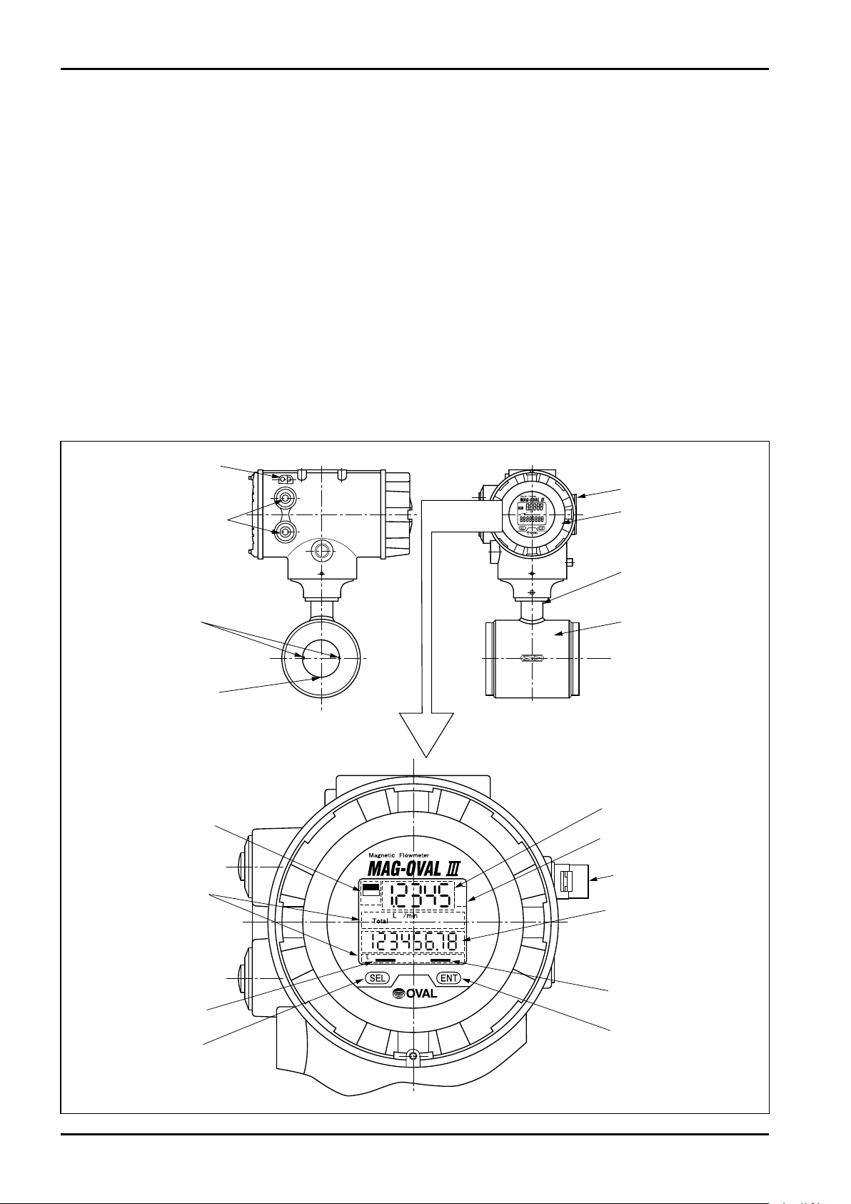
Electrodes
GND electrode
Cable entries
GND terminal
Transmitter
Adapter
Probe
Product nameplate
ERR.
ALM.
Alarm/Error
indicator
[ENT] key indicator
[SEL] key
indicator
[SEL] key
[ENT] key
Magnet
LCD Upper row
instant flow rate indicator
LCD bottom row
total flow indicator
Unit display
Unit display
1. GENERAL
Electromagnetic flowmeters operate on the basis of Faraday's law of electromagnetic induction. When a
conductive liquid flows through the magnetic field applied perpendicul ar to the direction of flow, an
electromotive force (EMF) is induced proportionally to the average velocity of flow according to Faraday's law. A
pair of electrodes located on the flow tube wall picks up the induced EMF which is then amplified in the
transmitter to determine the volumetric flow rate.
FEATURES
(1) Easy handling and low pressure loss contribute to low cost of installation and operation of the flowmeter,
providing excellent cost-effectiveness.
(2) Four kinds of electrodes are available for wetted area. Application to highly corrosive liquids is also
supported.
(3) In addition to magnet handling on the site, monitoring, various kinds of setting change, logging, loop test,
and self-diagnosis are available.
(4) Wide measuring range starting from zero.
■ Part names
4
Page 5
C−102-1-E
①
②
③
④
⑤
⑥
⑦
⑧
⑨
⑩
⑪
⑫
⑬
⑭
Magneti c F l ow m et e r
OVAL Corporation
MADEINJAPAN
MODEL
SERIALNo.
TAGNo.
FLUID
FLOWRANGE
MAX.PRESS
MAX.TEMP
ELECTRODE
POWER
DATE
ANALOGOUTPUT
PULSEOUTPUT
CAL.ZERO
CAL.FACTOR
A
Side view from Arrow A
2. BEFORE YOU BEGIN
Although this flowmeter is built and adjusted exactly to meet the customer specifications and, it is ready to
operate in your service by turning on the power, it is desirable for the operator to read this instruction manual
carefully for the best results in maintaining the stated accuracy and long life before initiating service operation.
You can avoid potential downtime of the equipment by observing the following instructions in particular.
(1) Confirm the operating conditions
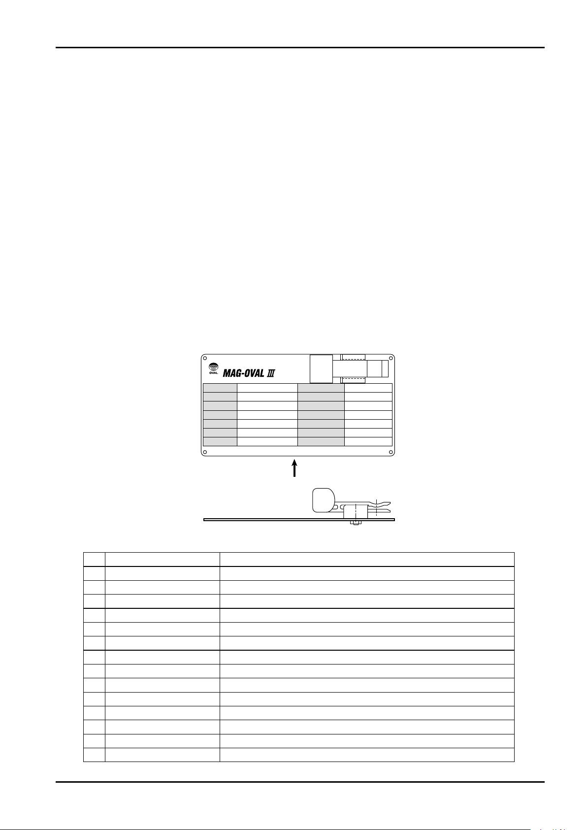
The operating conditions and major specifications of this flowmeter appear on the nameplate attached to the
transmitter. Verify that the conditions indicated agree with your particular operating conditions. If you are to
make measurement of corrosive liquids in particular, make sure of the compatibility of electrode materials, etc.
(2) About grounding
An electromagnetic flowmeter requires earth grounding. See the Grounding Instruction on page 12 for proper
grounding.
(3) Use with the flow tube filled with liquid
An electromagnetic flowmeter requires its internal space to be completely filled with the process liquid.
Ensure of a fully filled flow tube during operation.
(4) About field wiring
For intercabling between the electromagnetic flowmeter and receiving instrument, see the section "Wiring
Connections".
Please remember to check terminal numbers for correct connections before operation.
〈Explanation of items shown on nameplate〉
No. Item Description
(1) Product code Ex. MGW1-0501T17E-10A
(2) Product No.
(3) Instrument No. As designated
(4) Fluid measured Ex. Water
(5) Flow range Ex. 0 to 100m3/h
(6) Max. pressure Allowable max. pressure of flowmeter
(7) Max. temperature Allowable max. temperature of flowmeter
(8) Electrode material Ex. SUS316L (depending on selected type)
(9) Power spec. Ex. 85 to 264VAC 50/60Hz (depending on selected type)
(10)
Month/Year of shipment
(11)
Analog output 4 to 20mA
(12)
Pulse output At factored pulse Ex. 1L/P, At frequency pulse Ex. 1000Hz at F.S.
(13)
Calibration zero value
(14)
Calibration factor value
——
——
——
——
5
Page 6
C−102-1-E
Flow
5D min.
Probe
Flow
Partially open valve
10D min.
Probe
(1)
(2)
D: Nominal pipe diameter
Flow
Flow
Probe Probe
Tank
(A) (B)
3. PIPING INSTRUCTIONS
3.1 Straight Pipe Section
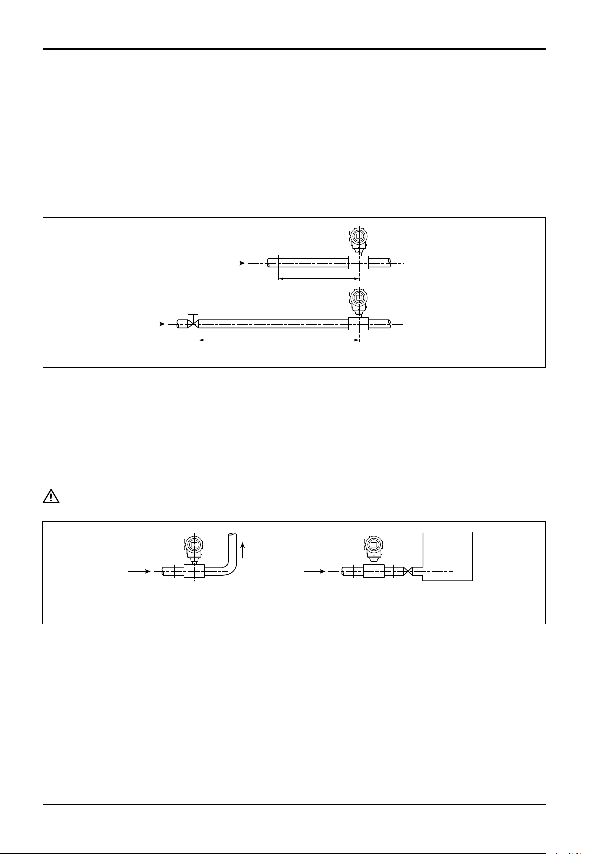
(1) Provide at least 5D (D: nominal pipe diameter) of straight piping upstream of the meter. For screw-in type
meters (3 to 15 mm in nominal diameter), no straight piping is required because of their long face-to-face
dimension with respect to their diameter.
(2) It is preferable that partially open valves or other devices that disturb the flow velocity pattern to be located
downstream of the meter. If such devices are desired to be placed upstream of the meter for some reason,
provide at least 10D of straight pipe section upstream of the probe.
Fig. 3.1 Standard Straight Pipes
3.2 Keeping the Flow Tube Completely Filled
(1) It is essential that the electromagnetic flowmeter be installed in a pipeline completely filled with the process
fluid.
(2) In cases of horizontal installation or vertical installation where the fluid flows top to bottom, we recommend
providing a rising pipe or maintaining sufficiently large hydraulic head downstream, for these piping
arrangements are likely to create empty or partially filled conditions. (See Figure 3.2)
CAUTION: False output pulses may be produced if the flow tube is not filled completely
with fluid.
Fig. 3.2 Proper Examples of Downstream Piping
6
Page 7
C−102-1-E
Electrodes
FLOW
FLOW
Horizontal run
Transmitter up with
axis of electrodes
horizontal
Vertical run
Cable entries pointing
downward
Bottom → Top
flow direction
is preferable.
Cable entries
(face down)
UP
Probe
Blow pipe
Downstream
valve
Bypass
Upstream
valve
Vertical flow direction
Valve
3.3 Physical Orientation of the Probe
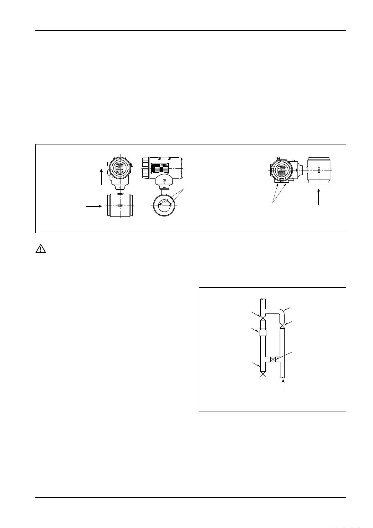
The probe may be installed in any physical orientation as long as the flow tube is completely filled with the
process fluid.
Keep in mind the following precautions, however.
(1) Horizontal run
In a horizontal line, keep electrodes axes on a level plane to minimize the risk of electrodes being insulated
momentarily due to suspended gas bubbles.
(2) Vertical run
In a vertical line, avoid a transmitter orientation with cable entry pointing upward to prevent rainwater from
entering the transmitter.
Fig. 3.3
CAUTION: With liquids that contain suspended solids or liquids that can separate easily, a
vertical run is suggested to reduce the possibility of solids deposition, wear and
separation to a minimum.
3.4 Bypass Line
We recommend to provide a bypass line to facilitate
maintenance and inspection.
Particularly in a vertical run, it is desirable that the
piping be arranged to facilitate removal of solids
build-up inside the pipe line.
Fig. 3.4 Vertical Piping Example
7
Page 8

C−102-1-E
Flow
Probe
Flow control valve
Probe
Lining
Seal face
(A) (B)
Gasket
(Must be in place.)
Do not seal on threads.
Flow
Upstream valve
Probe
Negative press. relief valve
Downstream valve
3.5 Prevention of Negative Pressure
In order to maintain a long-term service life of the
pro be, take pos i t ive measu res to elimi n ate
circumstances that can create negative pressure
in the pipeline.
(1) If b oth upstream a nd do wnst ream val ves
remain closed with fluid temperature higher
than that of the atmosphere, fluid contraction
may ta ke place as the fluid co ols down ,
creating negative pressure in the enclosed
space of pipeline. You can solve this problem
by providing a negative pressure relief valve
near the probe.
(2) If a vertical piping continues downstream of
the probe:
While stopping or adjusting the fluid flow with
the upstream valve of flowmeter, negative
pressure can be created in the pipeline. To
prevent this condition, stop or adjust the fluid
flow with the downstream valve.
Fig. 3.5 Piping Example to Prevent Negative Pressure (1)
Fig. 3.6 Piping Example to Prevent Negative Pressure (2)
3.6 Installation Location
Avoid locations such as:
(1) Near motors, transformers, or heavy electrical equipment
(2) Inaccessible for maintenance and inspection
(3) Temperature varies widely or vibration is excessive
(4) Potential risk of submergence
4. PROBE INSTALLATION
4.1 Screw-in Type (nominal sizes 3 to 15mm)
(1) Process connection is of screw-in type. By using dedicated unions, be sure to seal the end face of probe
(lining surface). Never apply a seal to threads as it is likely to cause unexpected trouble.
8
Fig. 4.1
Page 9
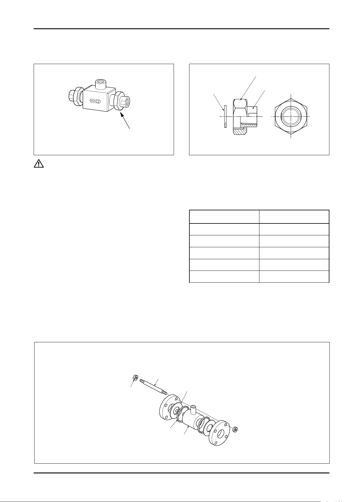
(2) Union and other joints should be of dedicated accessories furnished for connecting pipes.
Union fitting
Tightening nut
Gasket
Rc (PT) screw adapter
Hex nut
Connecting bolt
Flange gasket
Adjust ring
Probe
Use of nonstandard fittings can lead to unexpected trouble.
Fig. 4.2 Example of Unions Installed in Place Fig. 4.3 Union Fitting (accessory for piping)
CAUTION: Install the transmitter securely.
4.2 Wafer Type (nominal sizes 25 to 150mm)
C−102-1-E
Install the meter observing the following precautions:
Flange Tightening Torque Specifications
(1) Protection of probe's linings
a. Exercise care to avoid damage to the linings of
probe.
Nominal size (mm) Torque (N・m)
25, 40 39 to 54
b. Do not fail to use flange gaskets when making
pipe connections.
c. Tighten connecting bolts carefully to avoid
uneven tightening or over tightening.
( R efe r to th e f l an g e ti g ht e ni n g to r qu e
specifications in the table on the right.)
50 70
80 54
100 78
150 125
(2) Maintaining accuracy
a. To ensure concentric alignment of the probe,
do not fail to use the adjust rings furnished (or
adjust collars for nominal size 150mm meter
with JIS 10K flange rating).
b. Exercise care not to let flange gaskets protrude
inside the pipe.
◆ Installing adjust rings ◆ Nominal sizes 25mm to 150mm
(For nominal size of 150mm with flange rating of JIS 10K, see figure 4.5 on the next page.)
Fig. 4.4
9
Page 10
C−102-1-E
Hex nut
Connecting bolt
Flange gasket
Adjust collar
(Install four adjust collars
uniformly 90° apart.)
Probe
Installation on a horizontal pipe is shown with dotted lines.
2″ Pipe
Adapter
Sec A-A
181.6
A A
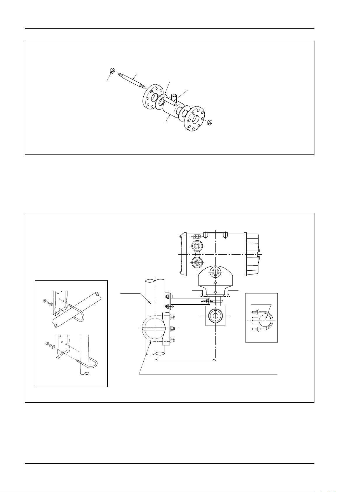
◆ Installing adjust collars ◆ Nominal size 150mm, flange rating JIS 10K
Fig. 4.5
4.3 Transmitter Installation
(1) Securing the integral transmitter (nominal size 3 to 6mm):
For the screw-in type (nominal size 3 to 6mm), tubes are too thin to support the meter.
Therefore, secure the transmitter in the manner shown in the figure below.
Using the U-bolt and mounting bracket
supplied with the flowmeter, fix the
flowmeter to a horizontal or vertical pipe
with nominal diameter of 2″.
* Pipe is not supplied with the flowmeter.
Mounting to a horizontal pipe
Mounting to a vertical pipe
Fig. 4.6 MAG-OVAL III Transmitter Hold-down Hardware
10
Page 11
C−102-1-E
Display cover
Hex key (M4)
Display cover
A flat tool that
does not damage
the finish
Turn
Fitting screw (M3)
Display unit
Display unit
Pull
Connector pins
Display unit
Connector
socket
Display unit
Press along
the guide
Guide hole
Guide pin
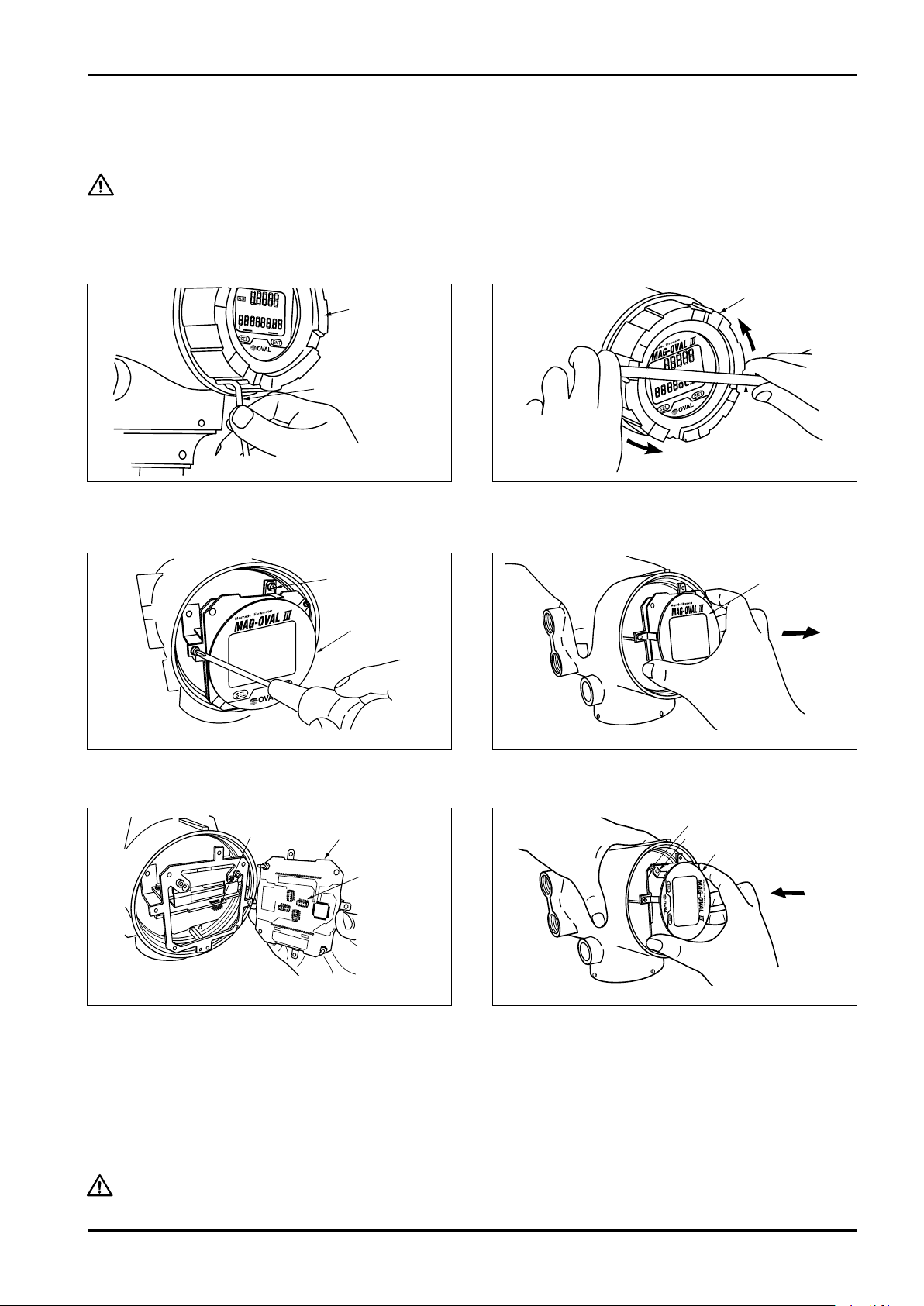
(2) Procedure to tilt the LCD display to the desired angle:
The display unit in its housing is rotatable in increments of 90 degrees through 360 degrees.
By changing the LCD display orientation, you can achieve optimum viewability also in a vertical line.
CAUTION: Do not forget to turn off the power before beginning this procedure. Another
precaution to remember is to eliminate static charges from the operator's body.
◆ Procedure to adjust angular orientation of display ◆
Fig. 4.7
(1) Using hex wrench, loosen the locking setscrew
(M4) securing the display cover in the locked
position.
Fig. 4.9
(3) Remove the mounting screws (4 places) with a
phillips screwdriver and detach the display unit.
Fig. 4.8
(2) Using a flat tool, loosen the display cover by
carefully turning it counterclockwise and hand
rotate it further until the cover comes off.
Fig. 4.10
(4) By pulling the display unit toward you, remove it.
Fig. 4.11
(5) The display unit is rotatable in 90° steps. Confirm
the locations of connector pins on the transmitter
body and mating sockets on the display unit.
(6) At the desired physical orientation of display unit,
rotatable in 90° steps, align four guide pins of the
unit with two mating guide holes and install into
Fig. 4.12
place by pressing it in a direction perpendicular
to its mating surface.
After determining the angular orientation of display unit, install display unit fitting screws, display cover, and
setscrew to lock the cover. Now the orientation adjustment is complete.
CAUTION: Install the display cover to the housing securely by tightening with a flat tool,
ensuring that no gap exists before tightening the locking setscrew.
11
Page 12
C−102-1-E
Terminal block
cover
Terminal block cover
Turn
A flat tool that does
not damage the finish
GND terminal
Probe
Metal
pipe
GND terminal
Probe
Metal
pipe
GND terminal
Probe
Resin
pipe
Internal ground terminal
Power terminal
block
Terminal board
Output signal
terminal block
Cable entries
5. GROUNDING
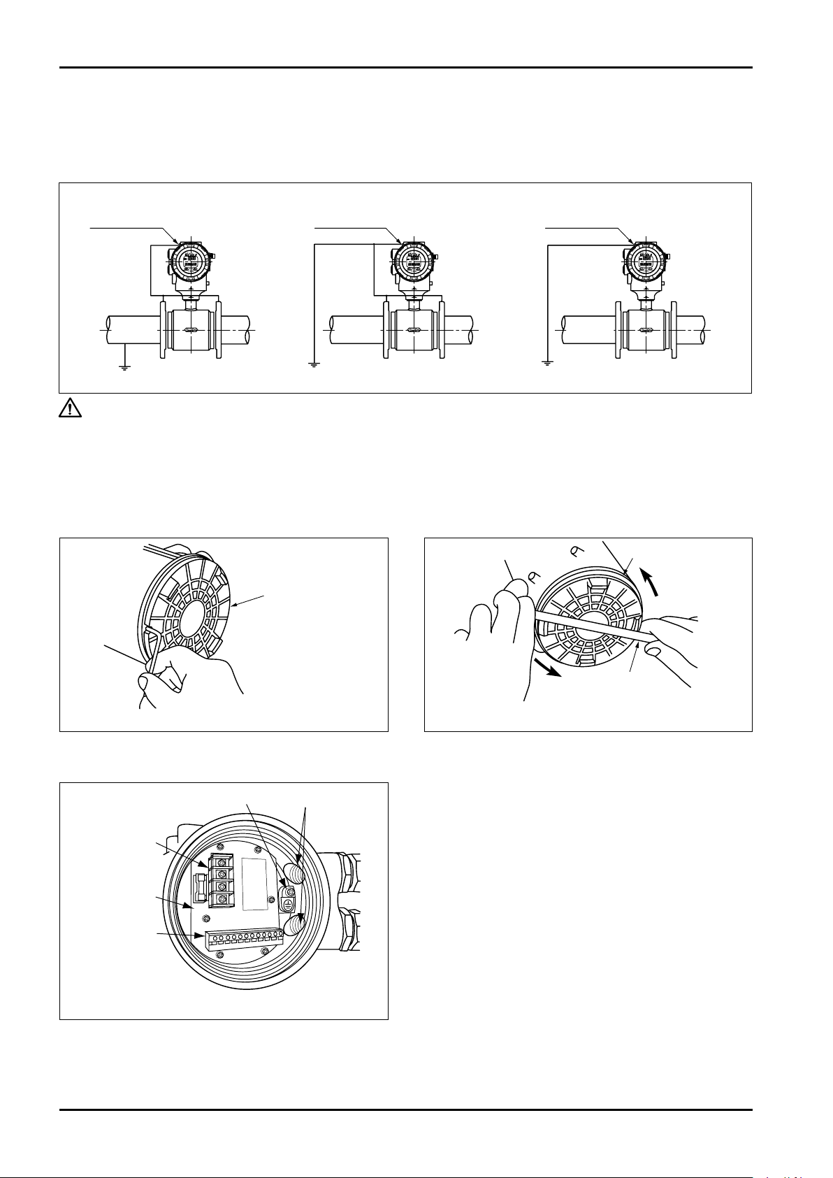
The electromotive force detected across electrodes of the probe is a very weak voltage measured against the
reference potential of metered liquid. Accordingly, earth grounding (better than Class C grounding) is essential to
maintain the probe and metered liquid at the same potential. Illustrated below are the proper grounding procedures.
Grounded metal pipeline
Ungrounded metal pipeline Plastic or lined pipeline
Fig. 5.1
CAUTION: Do not connect to earth ground of heavy electrical equipment.
Connect the ground wire for the transmitter to external ground terminal or internal
ground terminal.
6. WIRING CONNECTIONS
6.1 Power and Output Signal Wiring Connections
Terminals for wiring connections are found at the back of transmitter housing. Remove the cover and make wiring connections.
(1) Using hex wrench, loosen the locking setscrew
(3) Separating the cover provides access to the
12
Fig. 6.1
(M4 hex socket head) securing the cover.
Fig. 6.3 Terminal Board
terminal board with cable entrance openings,
int ernal ear t h grou nd termi nal and ter minal
blocks for power and output signals.
Fig.6.2 Terminal Block Cover Removal
(2) Using a flat tool, carefully loosen the terminal
cover by rotating it counterclockwise and turning
further by hand until it comes off.
Page 13
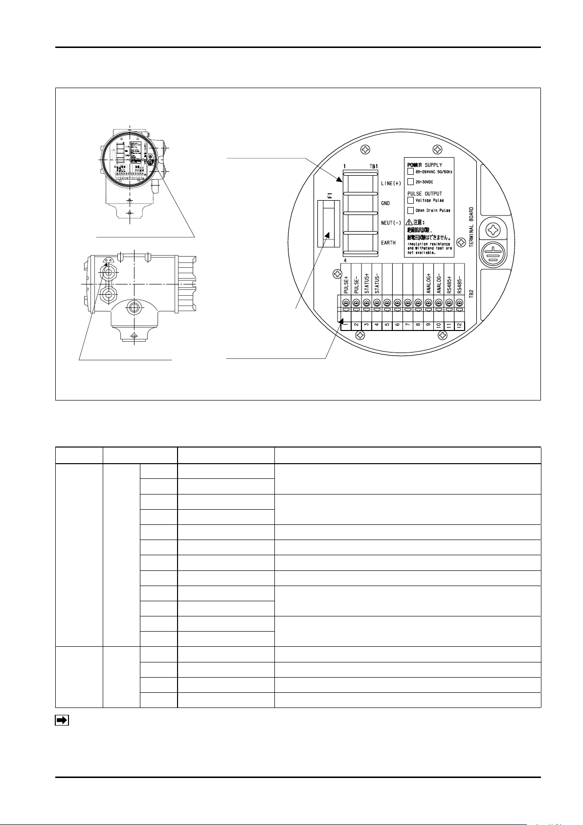
6.2 Wiring Connection Diagram
Power fuse
Output signal terminal (TB2)
screwless terminal
Internal ground terminal
External ground terminal
Power terminal (TB1)
screw size: M4
GND terminal location Details of terminal block
C−102-1-E
Fig. 6.4 Connecting Terminal Layout
6.3 Power and Output Signal Terminal Identification
Item Terminal No. Label Description
1 PULSE +
2 PULSE −
3 STATUS +
4 STATUS −
5 Unused
6 Unused
7 Unused
8 Unused
9 ANALOG +
10 ANALOG −
11 RS485 +
12 RS485 −
1 LINE(+) Power (with DC power: + )
2 GND Ground
3 NEUT(−) Power (with DC power: - )
4 EARTH Ground
Output signal
Power
TB2
TB1
Pulse output
(Open drain pulse output, or voltage pulse output)
Status output
(Open collector output)
Analog output
RS-485 communication
Note: Ground terminal "EARTH" shall be used for grounding. Ground terminal "EARTH" of this
flowmeter is internally connected to "GND".
13
Page 14
C−102-1-E
ANALOG+
ANALOG-
R
R
R
STATUS+
STATUS -
Receiver
Receiver Receiver
Receiver
ON
PULSE+
PULSE-
PULSE-
E:18V
R
E
ON
PULSE+
30VDC
50mA Max.
30VDC
50mA Max.
Line
capacity C
Line
capacity C
R 2.2kΩ
510Ω Max.
6.4 Wiring Connection Instruction
The screw size for cable entry is G1/2.
For connections to terminals, use the following crimping terminals.
Terminal name Recommended crimping terminal
Power terminal Round crimping terminal for M4
Output signal terminal
(Screwless terminal block)
No crimping terminal is required.
Use a cable of 0.2 to 1.25mm2.
Standard wire strip length: 11mm
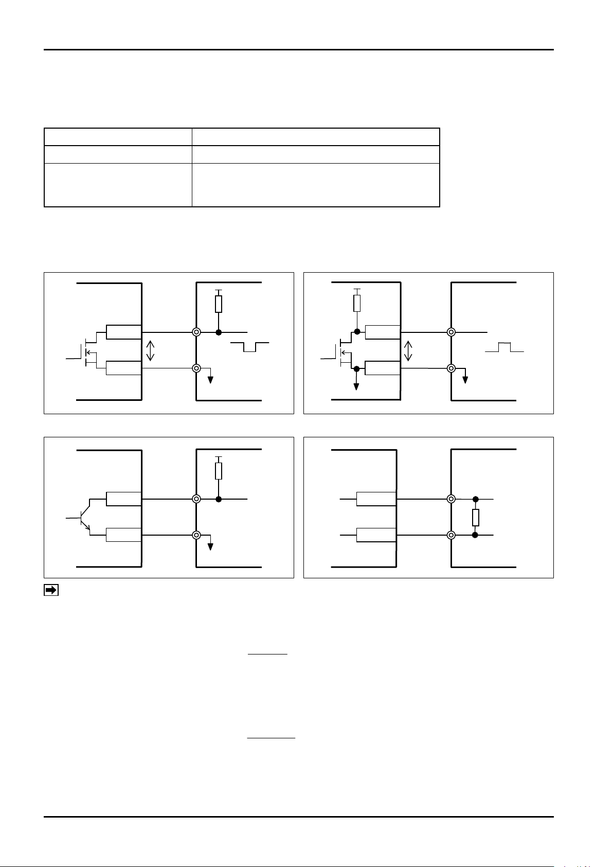
■ Connection to receiver
Open drain pulse output Voltage pulse output
Status output Analog output
0.1
R X C
NOTE: The tran smission len gth of pulse output is restricted by the outpu t frequency or receiver
specifications.
When setting open drain pulse
The pulse output waveform is attenuated by resistance R and line capacity C of the receiver.
The output frequency shall be set to F [Hz] < .
Line capacity C shall be set to 0.1μF/km.
When setting voltage pulse
The pulse output waveform is attenuated by resistance R and line capacity C in the flowmeter.
(The resistance factor of R is included in the following coefficient.)
The output frequency shall be set to F [Hz] < .
0.1
4400 X C
Line capacity C shall be set to 0.1μF/km.
14
Page 15

C−102-1-E
7. START-UP
(1) Upon completion of meter installation and field wiring connections, reaffirm the following:
a. Is the meter correctly installed? Is the flow direction correct?
b. Is the flow tube completely filled with the fluid?
c. Is the grounding correctly done?
(2) After filling the flow tube with the fluid, turn the power on.
a. On power-up, allow at least a 30 minute warm-up period.
b. When fluid flows, a signal (pulse and analog) proportionate to the flow is output and instantaneous flow
rate (default) is displayed on the top row of the LCD of the transmitter and accumulated total flow or
resettable total flow is displayed on the bottom row of the LCD. (The display can be selected by setting.)
(3) Using the two magnet switches in the transmitter, you can confirm or change parameters, such as full scale
and pulse units, and change the LCD display menus.
8. MAINTENANCE
Every MAG-OVAL III leaves the factory under stringent quality control. As long as it is placed under proper
conditions, it will perform satisfactorily over long periods of time. If trouble arises, diagnose the nature of trouble
according to the troubleshooting chart below for the possible solution.
When error alarm is being generated, check the detail of error in accordance with "20. ERROR/ALARM STATUS
LIST".
Problems
No Output
Unstable Zero
Unstable Output
○
○
○
○
○
○ ○
○ ○ ○ ○
○ ○ ○
○ ○ ○
○ ○ ○
○ ○ ○
○ ○
○ ○
○ ○
○ ○
○
○
Quick Troubleshooting
Confirm
Large Meter Error
(1) The wiring is correct.
(2) The power is sufficiently supplied.
(3) The fuse is not interrupted.
(4) The fluid is flowing, or valves are open.
(5) Receiving instrument specifications are matching. (Input pulse width, etc.)
(6) There is no leak from pipeline connections and valves.
(7) Earth ground is properly completed.
(8) Flow tube is completely filled. (There is no bubble entrapment.)
(9) There are no pulsations in the flow.
(10) Motors, transformers, or other heavy electrical equipment are not near the probe.
(11) Lining (electrodes) is free from slurry deposits.
(12) Fluid conductivity is uniform.
(13) Fluid is free from magnetic slurries.
(14) Piping conditions are correct. (Inaccurate probe centering or insufficient upstream pipe length)
(15) Full scale (flow range) is correct.
(16) Calibration factor and zeroing const. are correct.
(17) Primary standard against which the meter is compared is correct.
15
Page 16
C−102-1-E
ALM
(5) Error/Alarm indicator
(4) Total flow rate unit
display
(8) [SEL] key indicator
(9) [SEL] key
(1) Instant flow rate display
(Top row)
(2) Instant flow rate unit
(3) Total flow display
(Bottom row)
(6) [ENT] key indicator
(7) [ENT] key
ERR
9. TRANSMITTER DISPLAY AND OPERATION
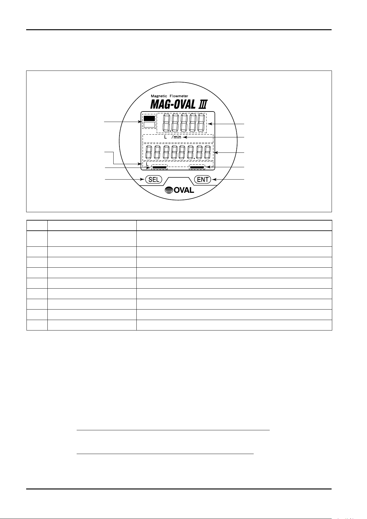
9.1 Explanation of Display
No. Item Description
Instant flow rate display (Top row)
(1)
Instant flow rate unit display Displays unit of instant flow rate.
(2)
Total flow display (Bottom row) Displays total flow or resettable total.
(3)
Total flow rate unit display Displays the unit of total flow.
(4)
Error/Alarm indicator Indicates the occurrence of error or alarm.
(5)
[ENT] key indicator Turns on when [ENT] key is operated.
(6)
[ENT] key [ENT] key. Operated by the use of attached selector magnet.
(7)
[SEL] key indicator Turns on when [SEL] key is operated.
(8)
[SEL] key [SEL] key. Operated by the use of attached selector magnet.
(9)
9.2 Operation Basics
9.2.1 Setup Mode and Measure Mode
This flowmeter is provided with two modes: "Measure mode" and "Setup mode".
"Measure mode" : The state after power on or at the completion of the Setup mode in item 11.
Displays instant flow rate and total flow.
The content of display can be changed by key operation.
After power on or at the completion of the Setup mode in item 11, the flowmeter returns to
→ Refer to "10.4 Screen Change for Instant and Total Flow Indication".
"Setup mode" : Checking and changing parameters and self-diagnosis are available from the Menu.
→ Refer to "11.1 Transition from Measure mode to Setup mode".
this state automatically.
Displays the instant flow rate. % flow rate and flow velocity can be selected
by switching.
16
Page 17
C−102-1-E
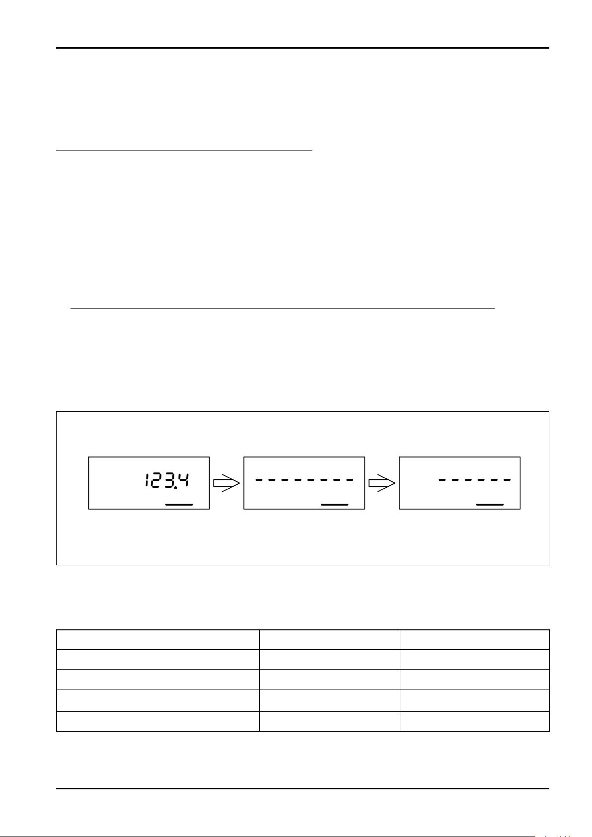
Ex. Indication when ENT key is set to ON
Indicator ON
Bar indication appears
on the bottom row display
Bars disappear
When all bars disappear,
press and hold ENT key
9.2.2 Key Operations
The keys of this flowmeter can be operated by placing the supplied magnet close to the "SEL" key and "ENT"
key in the magnet switch section.
Moving the magnet close to the SEL key or ENT key causes the magnet sensor to respond and the key entry is
set to ON.
The magnet sensor can respond through the glass screen.
■ Displayed messages during operation
Key operations include Ordinary depression (short key entry) and prolonged depression (press and hold key
entry).
(1) Ordinary depression
When the SEL key or ENT key is set to ON, the key indicator turns on. Setting the key entry OFF immediately
after the indicator turns on, starts ordinary operation.
If the key entry is kept ON, bars "- - - - - - -" appear on the bottom row display and then bars begin to
disappear at given time intervals.
If you set the key entry to OFF before the last bar disappears, it stays at the ordinary depression.
(2) Prolonged depression
Pressing and holding the SEL key or ENT key causes bars "- - - - - - -" to be displayed at the bottom row
display and then bars disappear one by one from the left.
Keeping the key ON until all bars disappear will start the prolonged depression.
(If you set the key to OFF before all bars disappear, it goes back to the ordinary operation (1).)
■ Description of each key operation
Each key operation executes the operation shown in the following table.
Key operation During Measure mode During Setup mode
SEL ((1) Ordinary depression) Changes display menu Switches operation, changes value
Press and hold SEL ((2) Prolonged depression)
ENT ((1) Ordinary depression)
Press and hold ENT ((2) Prolonged depression) Fixes the changes Fixes the changes
—
Switches between top and
bottom row displays
Return, Cancel
Shifts digits at the change of value
17
Page 18
C−102-1-E
*
*
*
Pressand
holdENT
ENT
ENT
SEL
*
*
10. MEASURE MODE
10.1 Measure Mode Screen
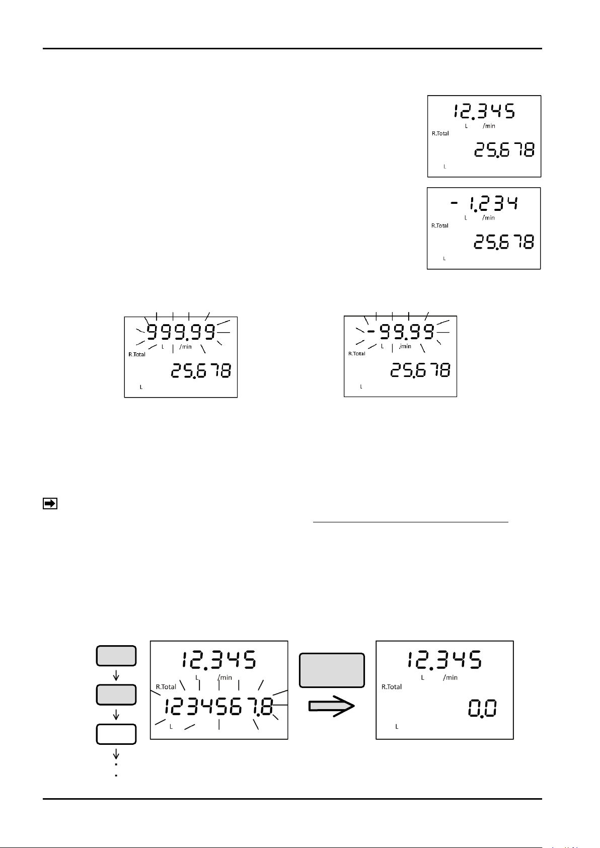
After power on or at the completion of Setup mode in item 11, the flowmeter
enters Measure mode and the following screen will appear on the display of the
flowmeter.
The upper row indicator shows instant flow rate.
This display allows instant flow rate, % flow rate, and flow velocity to be
changed by the key operation.
(* In case of negative flow display, the number of significant figures is reduced by
one digit.)
For the switching operation of the screen in Measure mode, refer to "10.4 Screen
Change for Instant and Total Flow Indication".
■ When instant flow rate exceeds the digits of display
(In case of negative indication)
Instant flow rate indication overflows and starts blinking. (In case of negative indication)
(* In case of negative flow display, the number of significant figures is reduced by one digit.)
The bottom row indicator shows instant flow rate.
Total flow indicates accumulated total flow from the time of manufacture or resettable total that can be reset as
required. This can be switched by the key operation.
NOTE: At the time of reverse flow, total flow will not be calculated.
When the total flow exceeds the digits of display, total flow returns to "0" and restarts totaling.
10.2 Resetting Resettable Total
When the bottom row indicator indicates resettable total flow (R.Total), pressing "ENT" selects the bottom row
indicator.
By pressing and holding "ENT" while the bottom row indicator is in the focused state (blinking), resetting the
resettable total can be executed.
18
Page 19
C−102-1-E
Displayed alternately
Displayed alternately
Displayed alternately
10.3 Error/Alarm and Status Display
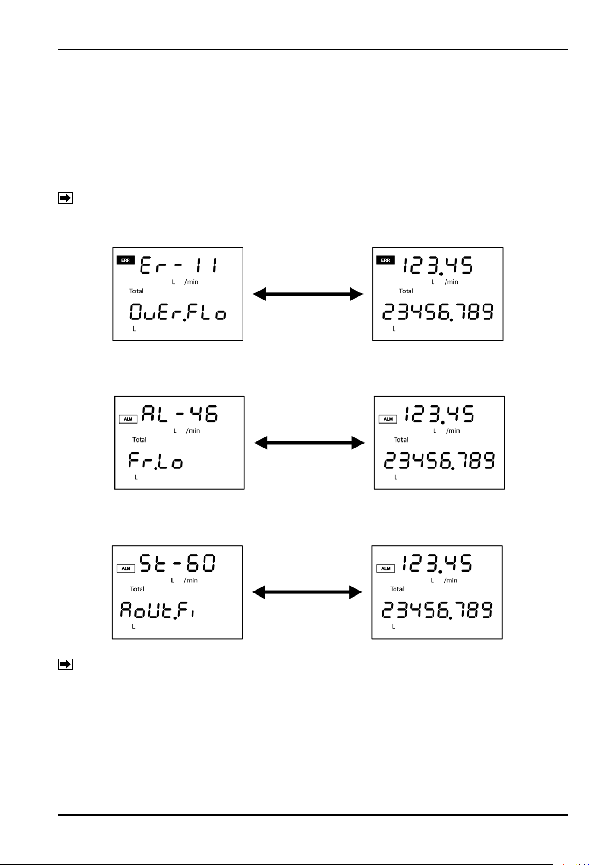
Error, alarm, and status report are notified by the LCD indicator.
At the occurrence of error, [ERR] indicator turns on at the upper left of the LCD.
At the occurrence of alarm, [ALM] indicator turns on at the upper left of the LCD.
The LCD top row indicates error/alarm occurred, status number and measurement value alternately.
(At 1-sec. intervals)
The LCD bottom row indicates error/alarm occurred, status description and measurement value alternately. (At
1-sec. intervals)
NOTE: For the details of number and description, refer to "20. ERROR/ALARM STATUS LIST".
■ Error indication (Ex.: Overflow error)
■ Error indication (Lower limit alarm)
■ Status display (During fixed analog output)
NOTE: Error/alarm indication continues until the problem is solved.
Status indication is given when operation is conducted from the outside through communication and
continues until the operation is completed.
19
Page 20
C−102-1-E
ENT
ENT
SEL
SEL
SEL
Display change of Measure mode
% flow rate indication
Instant flow rate indication
Resettable total
flow indication
Focused
(blinking)
Accumulated total
flow indication
Focus state (blinking) is terminated when
no key entry is made for 10 seconds.
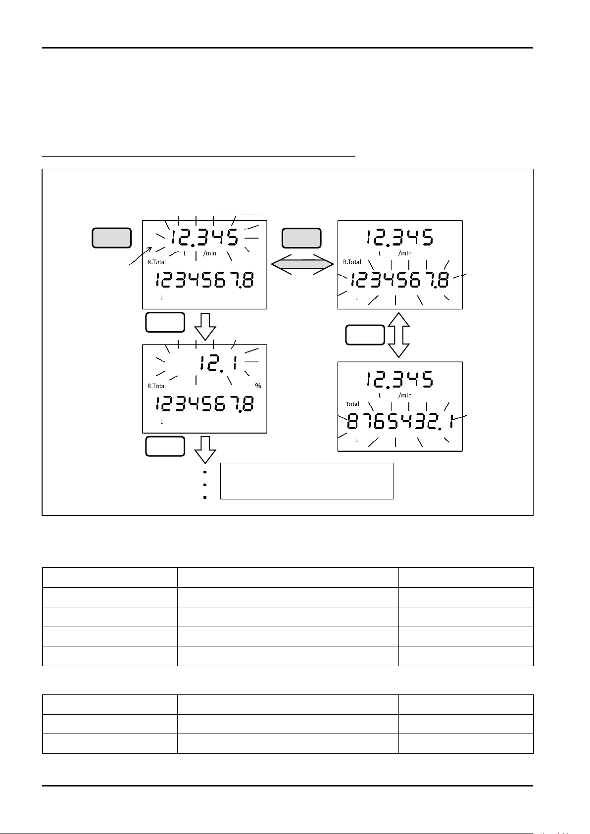
10.4 Screen Change for Instant and Total Flow Indication
In the Measure mode, the descriptions shown on the top row indicator and bottom row indicator can be
switched interchangeably.
To change the description to be displayed, set the top row or bottom row to the focused state (blinking) by
using the "ENT" key and change the description by the entry of the "SEL" key.
Focused state is terminated when no key entry is made for 10 seconds.
■ Selectable indication
Top row indicator
Display Item Description Example
Instant flow rate Indicates instant flow rate 12.345 L/min
% flow rate Indicates % flow rate with respect to metering range 12.1%
Flow velocity Indicates flow velocity 1.5 m/s
(MODE) For switching to Setup mode
Bottom row indicator
Display Item Description Example
Accumulated total flow Indicates accumulated total flow 8765432.1 L
Resettable total flow Indicates resettable total flow 1234567.8 L
20
—
Page 21
C−102-1-E
Pressand
holdENT
Pressand
holdENT
Pressand
holdENT
Pressand
holdSEL
Measure mode/Setup mode switching operation
In case password setting is effective
Setup mode
Measure mode
Returns to
Measure
mode
Password entry screen
Enter password
Password not matchPassword match
ENT
SEL
Pressand
holdENT
Pressand
holdSEL
11. OPERATIONS IN SETUP MODE
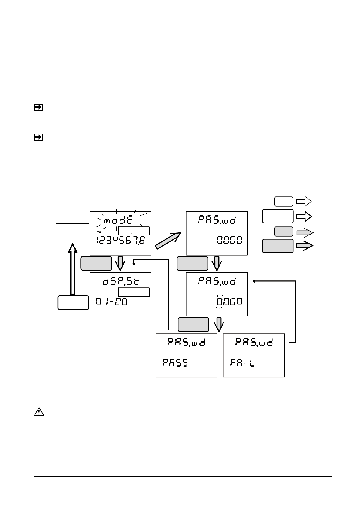
11.1 Transition from Measure Mode to Setup Mode
Reviewing and changing parameters are carried out in the Setup mode.
Transition from Measure mode to Setup mode is completed by the following operations.
Set the top row indicator to modE. (Refer to "10.4 Screen Change for Instant and Total Flow Indication".)
If you press and hold "ENT" while modE is blinking, transition to the Setup mode occurs.
NOTE: If password is effective by the setting, a screen for entering password is displayed.
Entering the correct password allows transition to the Setup mode.
(If wrong password is entered, the screen returns to the state of entering password.)
NOTE: The method of entering password is the same as that for parameter setting.
The password feature is "Invalid" and default password is "0000" in the setting at the factory shipment.
If you wish to validate the password feature, carefully manage your password. (If you forget your password,
contact nearest OVAL office or service center.)
CAUTION: To prevent accidental erroneous operation by parameter changing, changing
the setting shall be carried out while the flow is at pause.
21
Page 22
C−102-1-E
Menu operation in Measure mode
Layer code
Returns to
Measure mode
Top-most layer Bottom layer
Transition
between layers
SEL : Switches item
Press and hold SEL
: Returns to higher
layer
ENT : (Invalid)
Press and hold ENT
: Advances layer to
lower layer
Pressand
holdENT
SEL
Pressand
holdSEL
Pressand
holdSEL
Switches item
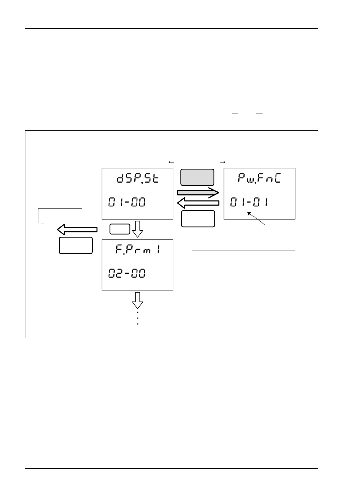
11.2 Menu Operation in Setup Mode
Transition of item in the Setup mode is available by "SEL" and "Press and hold ENT".
"Layer code" indicating the set item is displayed for 2 seconds for each item.
For the details of setting items, refer to "12. DISPLAY TRANSITION".
The display items are switched by "SEL", and transition to the lower layer is carried out by "Press and hold
ENT".
"Press and hold SEL" returns to the higher layer.
When "Press and hold SEL" is executed in the top-most layer (Layer code 01-00 to 14-00), exit from the Setup
mode occurs and the Measure mode is restored.
22
Page 23
C−102-1-E
Pressand
holdENT
Pressand
holdSEL
Parameter setting in selection system
Pressand
holdENT
SEL
SEL
SEL
SEL : Switches
setting value
Press and hold SEL :
Cancel
ENT : (Invalid)
Press and hold ENT :
Fix
Parameter Edit mode
When transition to Edit
mode is completed,
parameter starts blinking.
Automatically
returns to (1)
Entire screen blinks for a moment
and notifies that the change is fixed.
"Press and hold ENT" fixes the change.
Cancelled by
"Press and hold SEL"
(Parameter is not changed.)
Returns to Top
(1)
(2)
(3)
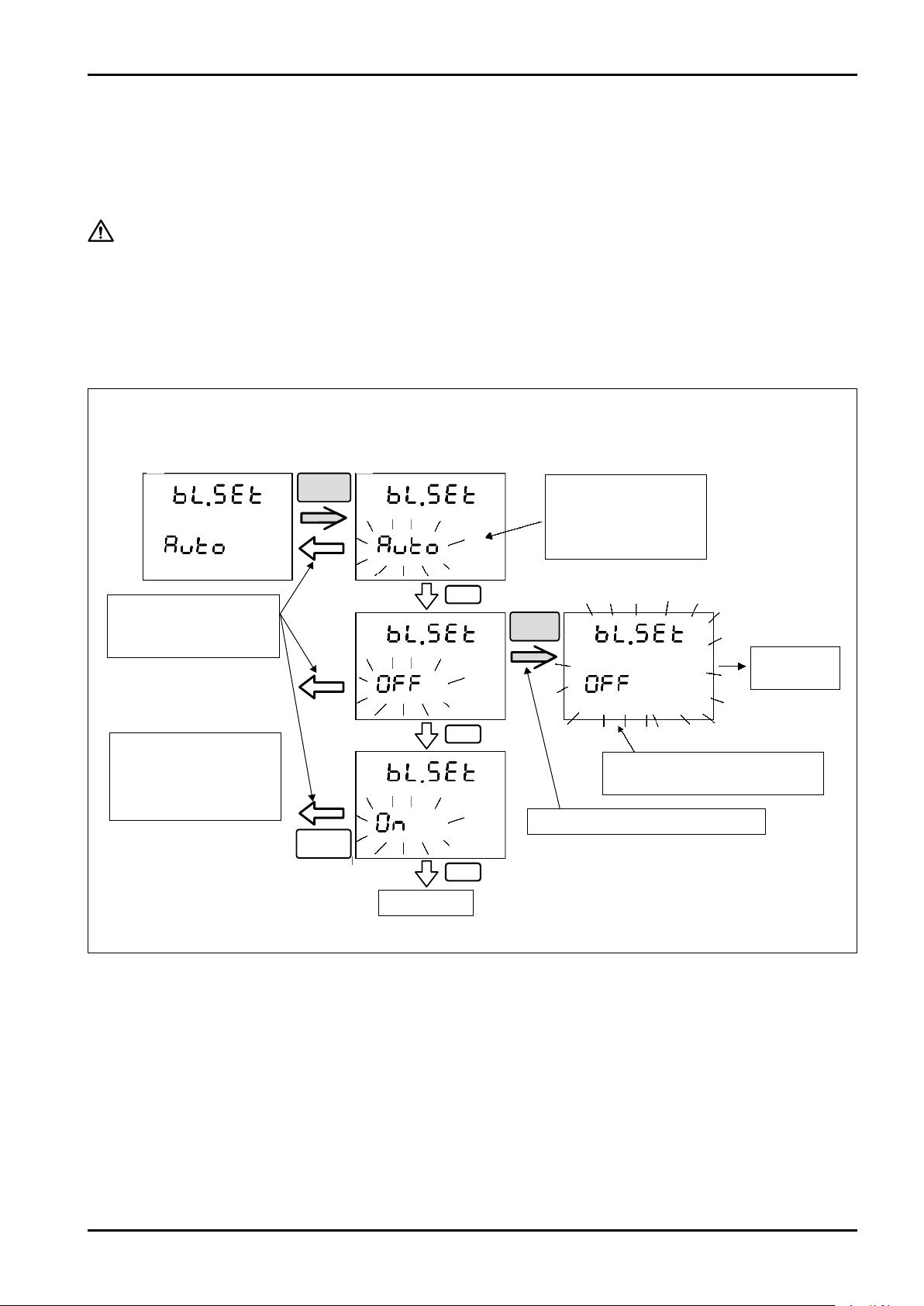
11.3 Changing Parameters
Changing parameters is executed by the following operations.
When selecting a setting item, the current content is displayed on the bottom row indicator.
"Press and hold ENT" enables transition to parameter Edit mode.
CAUTION: To prevent accidental erroneous operation by parameter changing, this
procedure shall be carried out while the flow is stopped.
11.3.1 Parameter Setting in Selection System (Ex. Changing backlight setting)
Parameter setting of selection system such as backlight setting (ON/OFF/AUTO) is carried out by the following
procedure.
23
Page 24
C−102-1-E
Pressand
holdENT
Pressand
holdSEL
Numeric parameter setting
Pressand
holdENT
SEL
ENT
Parameter Edit mode
When transition to Edit mode is completed,
the focused digit starts blinking.
Automatically
returns to (1)
Entire screen blinks for a moment
and notifies that the change is fixed.
Change the numeric value by "SEL".
Shift the digit by "ENT".
Fix by "Press and hold ENT".
(1)
(2)
(3)
SEL : Changes
numeral
Press and hold SEL
: Cancel
ENT : Shifts digit
Press and hold ENT
: Fix
Cancelled by
"Press and hold SEL"
(Parameter is not changed.)
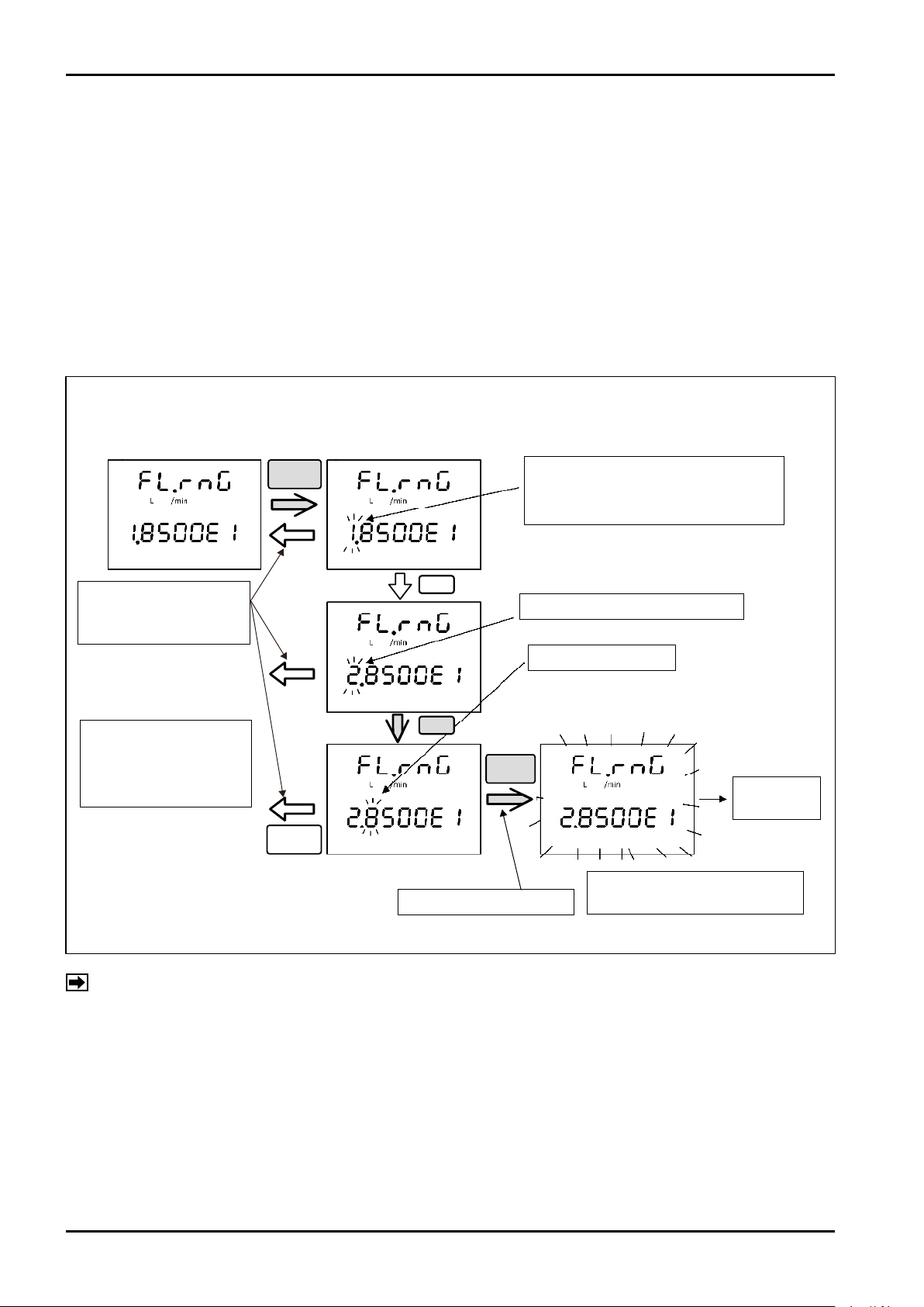
11.3.2 Setting Numeric Parameters (Ex. Changing flow range setting)
When entering the Edit mode, the top-most digit of numeral is focused (blinking).
Change the value of the blinking digit focused by "SEL" and shift the focused digit to the right by pressing
"ENT".
Then "Press and hold ENT", to fix the change.
"Press and hold SEL" can cancel the setting.
(Returns to the original setting.)
Parameters with decimal point are in the fixed point type or exponential type.
For exponential type, refer to "11.3.3 Viewing Exponential Indication".
NOTE: If the numeral entered exceeds the parameter settable range, the edit screen of (2) is restored after
"Set Err" is indicated. Change the numeral and fix the numeral again or use "Press and hold SEL" to
cancel.
24
Page 25

C−102-1-E
11.3.3 Viewing Exponential Indication
Exponential indication is a notation of effective digit X exponent (10 to the nth power).
For example, to set "123.45", 1.2345 X 10² is given. Therefore, enter 1.2345E2. (102 = 100)
Setting negative exponent is also available. For example, to set "0.012345", 1.2345 X 10⁻² is given in
exponential indication. Therefore, enter 1.2345-2. (10-2 = 0.01)
For the symbol of exponent, "-" and "E" can be switched by "SEL" by focusing the "E" at the second digit from
the right. ("-" shows negative exponent and "E" shows positive exponent.)
25
Page 26
C−102-1-E
"SEL"
"Press and hold SEL"
"Press and hold ENT"
Other
ENT
Displays instant flow rate
Total flow
Displays % flow rate
Resettable total flow
Displays flow velocity
Setup mode
Set password
Set password function
Set password
Set flow display
Instant flow rate units
No. of instant flow rate digits
below decimal point
Total flow units
No. of total flow digits below
decimal point
Set backlight
Screen display update cycle
F.dECP
m/s
modE
t.dECP
t.unit
FL.SEt
Parameter third item
Parameter third item
Pw.SEt
Pw.OPt
F.unit
Set flow parameter 2
F.Prm2
Set flow parameter 3
F.Prm3
Parameter major item
[Top row display] Selects display [Bottom row display] Displays total flow
%
Enter password
00-00
01-00
02-00
03-00
04-00
05-00
06-00
07-00
08-00
09-00
10-00
11-00
12-00
13-00
14-00
PAS.wd
Parameter name
Layer code (Major item ― Secondary item ― Third item)
Parameter
display symbol
01-01
01-02
01-03
01-04
Set display
dSP.St
Set flow parameter 1
F.Prm1
Set self-diagnosis
diAG.S
Loop test
LP.tSt
Analog output trim function
A.trim
Self-check function
CHECK
Set analog output
A.Out
Set pulse output
P.Out
Set error output
Er.Out
Set alarm
ALArm
Set status output
S.Out
Select status output object
St.SEL
Parameter secondary item
bL.SEt
dP.CyC
Pw.FnC
01-01-01
01-02-01
01-02-02
01-02-03
01-02-04
Times of resettable total overflow
rt.oF
01-02-05
Times of total value overflow
t.oF
01-02-06
01-01-02
**.***
*****
*****
**.**
**.**
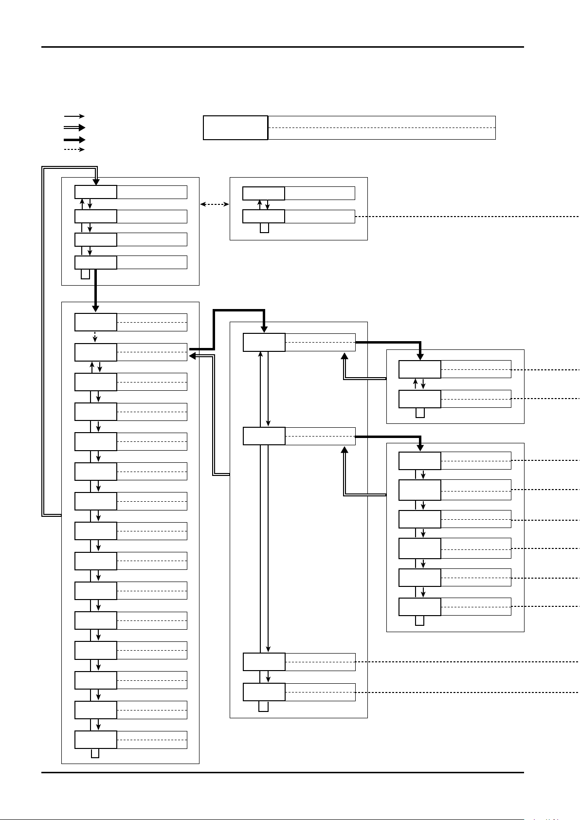
12. DISPLAY TRANSITION
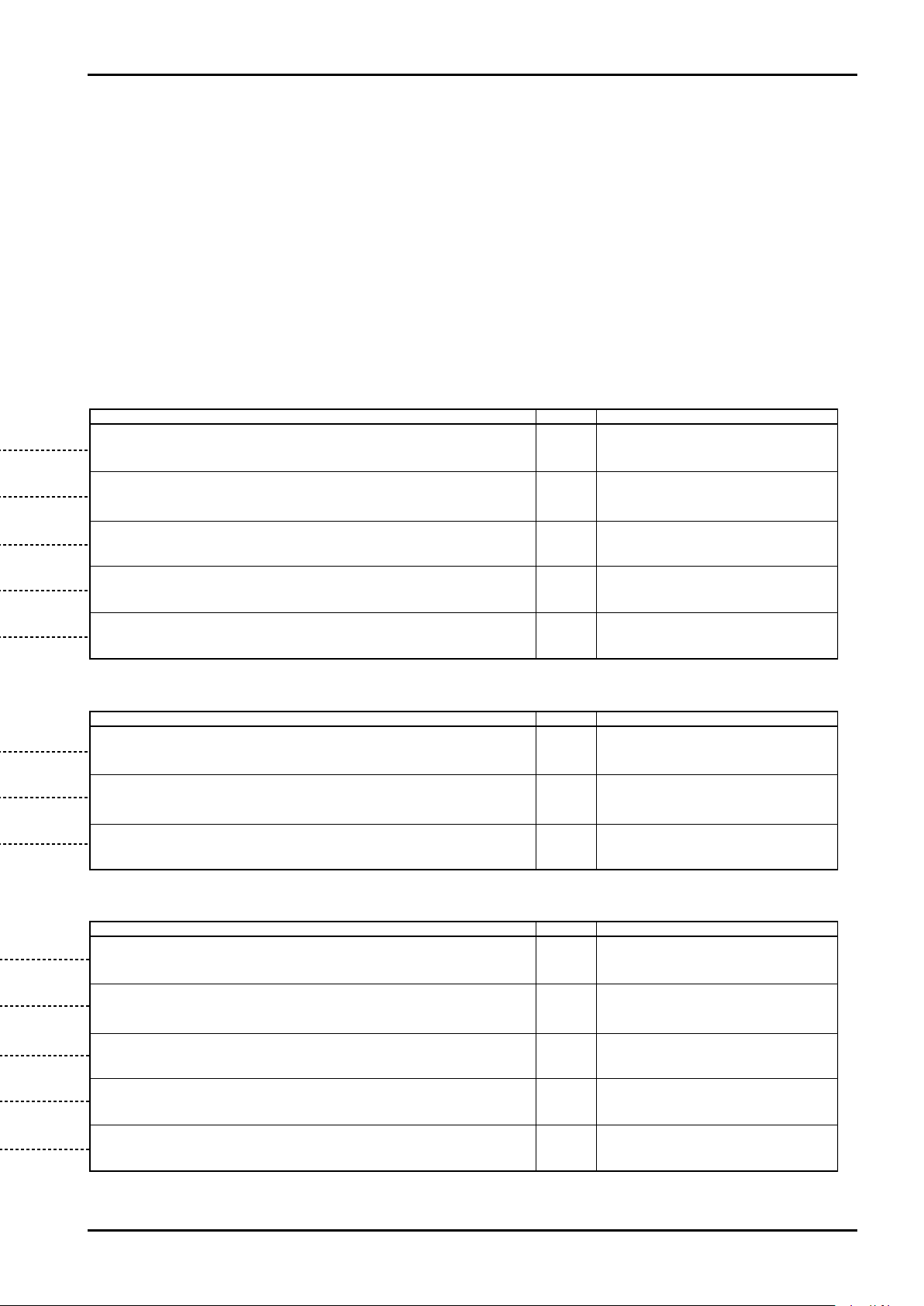
12.1 Display Transition (1) Setting Display
26
Page 27
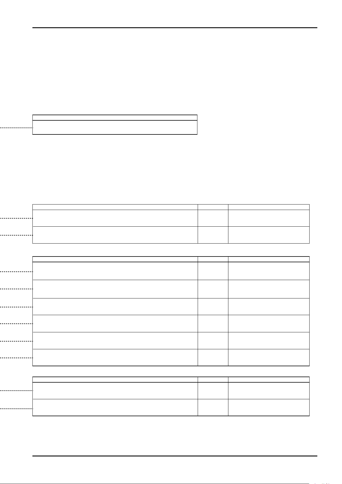
Description of item
Content of parameter Default Setting range
Content of parameter Default Setting range
Content of parameter Default
Setting range
500
100, 300, 500, 1000 (ms)
Auto
Can change the ON/OFF setting of LCD backlight.
0 to 3 digits
* 0 digit: Indication by integer
0 to 3 digits
* 0 digit: Indication by integer
0
0
As
specified
Depends on
measurement
range
Depends on
measurement
range
As
specified
L, m
3
, kg, t, gal
On (Valid), OFF (Invalid)
OFF
0000 to 9999
0000
Allows selecting valid/invalid of password feature. Selecting "ON" causes
password entry to be required before entering the Setup menu screen, preventing
the parameter from being changed easily.
Allows setting a password. To validate this setting, the password feature shall be
set to
"On"
by password feature setting. Note that password change is impossible
if you forget your password.
Display of optionally resettable total flow
Operation: Reset this display by "press and hold ENT" while resettable total is blinking.
Can change the unit of instant flow rate indicated on the botto m row display.
Note: At the setting change of volumetric flow rate ⇔ mass flow rate, the total value is reset.
* In case of mass flow rate display, den sity shall be set ad ditionally as fixed convers ion factor.
Can change the number of digits below decimal point of instant flow rate indicated
on the top row display.
Can change the unit of total flow indicated on the bot tom row display. (Common to accumu-
lated total and resettable total)
* In case of mass flow rate display, density shall be set additiona lly as fixed conversion factor.
Can change the number of digits below decimal point of total flow indicated on the
top row display.
(Common to accumulated total and resettable total)
Number of times the total value indicated on the bottom row display exceeds the
display digits (8 digits) and returns to
"0"
. Resetting the resettable total resets the
count to zero.
Number of times the total value indicated on the bottom row display exceeds the
display digits (8 digits) and returns to
"0"
.
Can change LCD display update cycle (ms). If viewing is difficult due to
display change, set the interval longer, and if quick review is required,
shorten the interval.
Unit of flow rate (Numerator):
L, m3, kg,
t, gal
Unit of time (Denominator): s, min, h, d
ON (lights always), OFF (unlit always)
Auto (Lights during operation, turns off
10 sec. after finishing operation)
Only for reference
Only for reference
C−102-1-E
27
Page 28
C−102-1-E
Measurement range
Flow measurement damping
Low cut
Low cut hysteresis
F.dAmP
F.Prm2
F.Prm3
00-00
01-00
02-00
03-00
04-00
05-00
06-00
07-00
08-00
09-00
10-00
11-00
12-00
13-00
14-00
PAS.wd
02-01
02-02
02-03
02-04
dSP.St
F.Prm1
diAG.S
LP.tSt
A.trim
CHECK
A.Out
P.Out
Er.Out
ALArm
04-01
04-02
04-03
04-04
04-05
Nominal diameter
dimtr
Zero point
CAL.0
Calibration factor
CAL.F
DC type basic cycle
dC.bAS
Coil exciting frequency
dr.Frq
S.Out
St.SEL
Parameter secondary item
Lo.Cut
LC.HyS
Fixed conversion factor
02-05
Con.FC
FL.rnG
Noise failure suppression
Auto gain compensation
AG.Com
03-01
03-02
Flow direction
03-03
FL.dir
In.SuP
*****
*****
m/s
modE
%
**.***
**.**
**.**
"SEL"
"Press and hold SEL"
"Press and hold ENT"
Other
Displays instant flow rate
Displays % flow rate
Displays flow velocity
Setup mode
Set flow parameter 2
Set flow parameter 3
Parameter major item
[Top row display] Selects display
Enter password
Set display
Set flow parameter 1
Set self-diagnosis
Loop test
Analog output trim function
Self-check function
Set analog output
Set pulse output
Set error output
Set alarm
Set status output
Select status output object
ENT
Total flow
Resettable total flow
[Bottom row display] Displays total flow
Parameter name
Layer code (Major item ― Secondary item ― Third item)
Parameter
display symbol
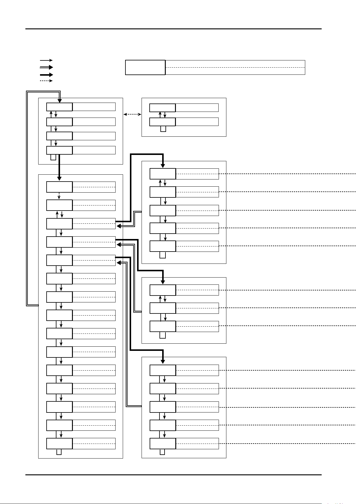
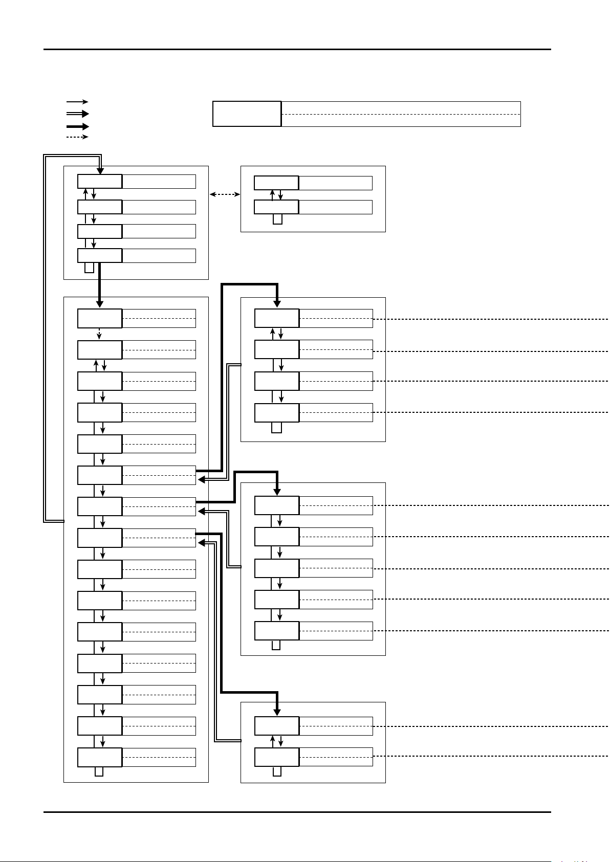
12.2 Display Transition (2) Setting Flow Parameter
28
Page 29
C−102-1-E
Content of parameter Default Setting range
0.50 to 99.99s (seconds)
On (Valid), OFF (Invalid)
OFF
OFF
1.0000E0
5
As
specified
0.50
0.0 to 100.0%
Can change the full scale of % flow rate (max. measured flow).
Can change damping time constant for flow measurement.
Affects the instant flow rate display and analog output.
* Time constant is the time required for the instruction to reach approx. 63% in the step response.
Can change the low cut flow. As flow measurement below setting is not carried out, this
is effective for preventing error output due to fluid oscillation (noise) at zero flow rate.
Setting is available with the rate (%) to the measurement range.
Can provide the low cut setting with 5% hysteresis.
Ex.: At the time of 5% low cut, cutting occurs up to 10% for the measurement
range as flow volume is increased. It is cut to 5% at the down time.
Can set the conversion factor of flow rate.
Used for fixed density conversion, etc. for conversion to mass flow rate.
0.0000E0 to 9.9999E9
(5 significant digits + 1 exponent digit)
Content of parameter Default Setting range
On (Valid), OFF (Invalid)
* As this model uses highly reliable parts, it is
unnecessary to set
"
Valid" in normal case.
PoS.FL
100
Regulates instant flow rate variation due to impulse type noise, etc.
The range for permitting variation is set by % to max. flow measured.
Automatically calibrates and compensates the variation of transmitter internal circuit due to ambient temperature, etc.
When this feature is validated, measurement is suspended (display and output are held) for approx. 0.5 sec. at intervals
of 24 min. Therefore, do not use this flowmeter in the system requiring response such as in batch measurement.
Sets the flow direction of measured fluid with respect to the flow direction (arrow
marking) of the probe.
1 to 100%
* 100% : Function invalid
"
PoS.FL" (Positive flow),
"
nEG.FL" (Negative flow)
Content of parameter Default Setting range
Factory
setting
Factory
setting
Factory
setting
Factory
setting
Factory
setting
Displays exciting frequency of probe coil.
* Cannot be changed.
Displays the nominal size of probe.
* Cannot be changed.
Displays zero point constant of probe.
* Cannot be changed.
Displays calibration factor of probe.
* Cannot be changed.
Displays measurement reference frequency at the time of DC power on. (Only DC power model)
* Cannot be changed.
Value appropriate for your environment is
set at the time of factory shipment.
Appropriate value is set at the time of
factory shipment.
Appropriate value is set at the time of
factory shipment.
Appropriate value is set by the calibration of
actual flow at the time of factory shipment.
Appropriate value is set by the calibration of
actual flow at the time of factory shipment.
0.5 to 10m/s
by flow velocity conversion
29
Page 30
C−102-1-E
4mA output setting
20mA output setting
Analog output damping
20mA
F.Prm2
F.Prm3
00-00
01-00
02-00
03-00
04-00
05-00
06-00
07-00
08-00
09-00
10-00
11-00
12-00
13-00
14-00
PAS.wd
05-01
05-02
05-03
dSP.St
F.Prm1
diAG.S
LP.tSt
A.trim
CHECK
A.Out
P.Out
Er.Out
ALArm
06-01
06-02
06-03
06-04
06-05
Frequency factor
Fq.FAC
Flow rate factor
rt.FAC
Pulse output low cut
Lo.Cut
Pulse weight
wEit
Pulse calculation mode
P.modE
S.Out
St.SEL
Parameter secondary item
A.dAmP
Analog output low cut
05-04
Lo.Cut
4mA
Status output function
07-01
Status output mode
07-02
S.modE
S.FunC
m/s
modE
%
**.***
**.**
**.**
"SEL"
"Press and hold SEL"
"Press and hold ENT"
Other
ENT
Displays instant flow rate
Total flow
Displays % flow rate
Resettable total flow
Displays flow velocity
Setup mode
Set flow parameter 2
Set flow parameter 3
Parameter major item
[Top row display] Selects display [Bottom row display] Displays total flow
Enter password
Parameter name
Layer code (Major item ― Secondary item ― Third item)
Parameter
display symbol
Set display
Set flow parameter 1
Set self-diagnosis
Loop test
Analog output trim function
Self-check function
Set analog output
Set pulse output
Set error output
Set alarm
Set status output
Select status output object
*****
*****
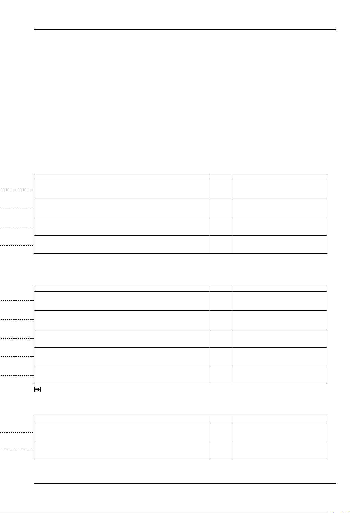
12.3 Display Transition (3) Setting Output Signal
30
Page 31
C−102-1-E
Content of parameter Default Setting range
0 to Measurement range setting
* Flow (5 significant digits + 1 exponent digit)
0.0 to 100.0s (seconds)
0.0
0.0
As
specified
As
specified
As
specified
As
specified
As
specified
0.0000E0
0 to Measurement range setting
* Flow (5 significant digits + 1 exponent digit)
Can change the analog output lower limit flow (flow at 4m A output).
When you change the measurement range, change this parameter as necessary.
* Unit is subject to the setting of ins tant flow rate display unit.
Can change the analog output upper limit flow (flow at 20mA output).
When you change the measurement range, change this parameter as necessary.
* Unit is subject to the setting of ins tant flow rate display unit.
Can change the time constant for ana log output damping.
This affe cts the flow measurement damping "F.dAmP" in double.
* Time constant refers to the time instruction reaches approx. 63% in step response.
Fixes the output to 4mA until a certain amount of flow is reached.
It is set in % to ma x. measurement flow.
* For details, refer to "ANALOG OUTPUT FUNCTION".
0.0 to 10.0%
Content of parameter Default Setting range
On ACt
no.FunC
Sets the allocation of status output.
* For details, refer to "15. STATUS OUTPUT FUNCTION".
Sets status output logic.
* For details, refer to "15. STATUS OUTPUT FUNCTION".
no.FunC : Status output not used
Err.StS : Error, alarm, status output
HL.ALA :
Higher and lower limit alarm output
FLo.dir : Flow direction
OFF.ACt : Off, Active
On.ACt : On, Active
Content of parameter Default Setting range
0.0
Can select pulse output mode. (Frequency pulse or Factored pulse)
* Note that changing this parameter resets the total value.
Sets the full-scale frequency of "Frequency pulse".
* This is not displayed when "Factored pulse" is selected.
Sets the flow rate at the full-scale frequency output of "frequency pulse".
* This is not displayed when "Factored pulse" is selected.
Stops output pulse until a certain amount of flow is reached.
Sets by the rate of pulse output to full-scale flow.
* This is not displayed when "Factored pulse" is selected.
Sets the flow rate per one pulse of "Factored pulse".
Unit is subject to the set ting of total flow unit.
* This is not displayed when "Frequency pulse" is selected.
"FrEq" (Frequency pulse)
"WEit" (Factored pulse)
1 to 10000 Hz
0 to Measurement range set flow
* 5 significant digits + exponent
0.0 to 10.0%
Set the flow rate so that the frequency
at max. flow rate is within 10,000 Hz.
* (5 significant digits + exponent)
(Note)
(Note)
(Note)
(Note)
NOTE: Changing these parameters resets the total value.
31
Page 32
C−102-1-E
Overflow error
Abnormal hardware error
Parameter alarm
H.FAiL
F.Prm2
F.Prm3
00-00
01-00
02-00
03-00
04-00
05-00
06-00
07-00
08-00
09-00
10-00
11-00
12-00
13-00
14-00
PAS.wd
08-01
08-02
08-03
dSP.St
F.Prm1
diAG.S
LP.tSt
A.trim
CHECK
A.Out
P.Out
Er.Out
ALArm
10-01
10-02
10-03
Low alarm point
AL.Lo
High/Low alarm hysteresis
AL.HyS
High alarm point
AL.Hi
S.Out
St.SEL
Parameter secondary item
Parameter major item
Prm.AL
Output saturation alarm
08-04
SAt.AL
OF.Err
Measurement error signal alarm
Empty tube detection alarm
Fixed output state
EmP.AL
08-05
08-06
08-07
FOut.S
Self-diagnosis execution state
08-08
diAG.S
SiG.AL
Analog output at error
09-01
Pulse output at error
09-02
Er.PLS
Er.AnA
m/s
modE
**.***
**.**
**.**
"SEL"
"Press and hold SEL"
"Press and hold ENT"
Other
Parameter name
Layer code (Major item ― Secondary item ― Third item)
Parameter
display symbol
ENT
Displays instant flow rate
Total flow
Displays % flow rate
Resettable total flow
Displays flow velocity
Setup mode
Set flow parameter 2
Set flow parameter 3
[Top row display] Selects display [Bottom row display] Displays total flow
Enter password
Set display
Set flow parameter 1
Set self-diagnosis
Loop test
Analog output trim function
Self-check function
Set analog output
Set pulse output
Set error output
Set alarm
Set status output
Select status output object
*****
*****
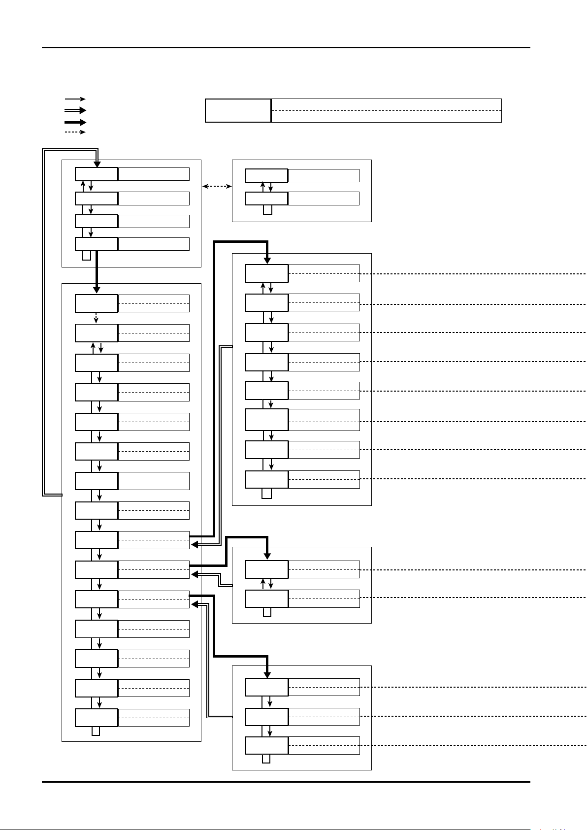
12.4 Display Transition (4) Setting Error and Alarm Output
32
Page 33
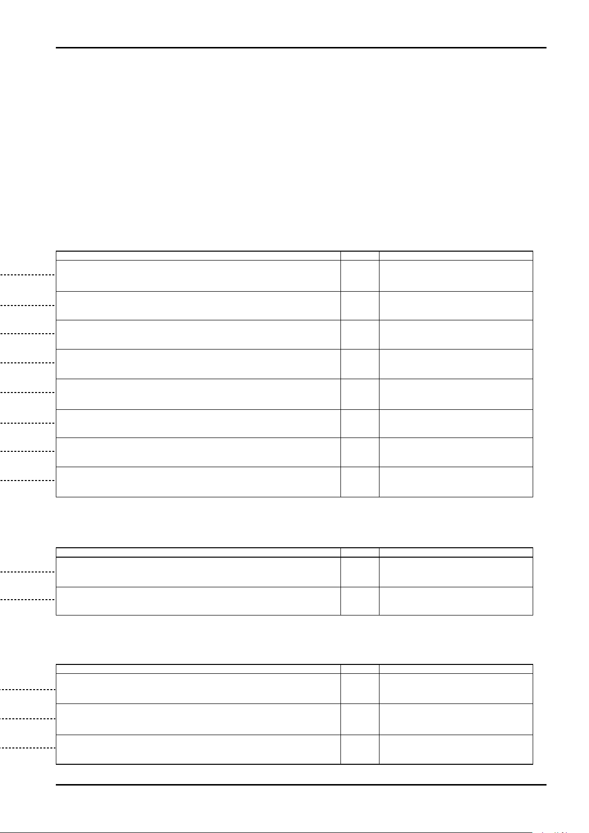
Content of parameter Default Setting range
On (Valid), OFF (Invalid)
On (Valid), OFF (Invalid)
On (Valid), OFF (Invalid)
On (Valid), OFF (Invalid)
On (Valid), OFF (Invalid)
On (Valid), OFF (Invalid)
On (Valid), OFF (Invalid)
On (Valid), OFF (Invalid)
0.0000E0
0.0000E0
0.0000E0
OFF
OFF
OFF
OFF
OFF
OFF
OFF
OFF
Content of parameter Default Setting range
ZEro
dn.SCLE
Can select the analog output status at the time of error detection.
* For details, refer to "ANALOG OUTPUT FUNCTION".
Outputs when flow exceeds the preset measurement range.
Outputs when there is an abnormal error in the flowmeter hardware.
Outputs when parameter setting is inappropriate.
Outputs when analog or pulse output exceeds the preset higher or lower limit.
Outputs alarm when measurement signal is abnormal (noise superimpose, etc.)
Outputs alarm when the electrode of probe is not wetted.
Outputs status while pulse and analog fixed outputs are being generated in a
loop test.
Outputs when self-diagnosis is being carried out by key operation or through
communication.
Sets the pulse output mode at the detection of an error.
* For details, refer to "PULSE OUTPUT FUNCTION".
"dn.SCLE" : Down scale (2.4mA),
"HoLd", "ZEro" : 4mA,
"no.FunC" : Not assigned,
"uP.SCLE" : Up scale (21.6mA)
"ZEro": 0Hz, "no.FunC": Not assigned,
"uP.SCLE": Up scale (110% of max.
output), "HoLd"
Content of parameter Default Setting range
Sets the High alarm point. When a flow greater than the preset flow occurs, this alarm turns
on. (Operates when status output function is assigned to High/Low alarm point setting.)
* Unit is subject to the setting of instant flow rate display unit.
Sets the Low alarm point. When a flow smaller than the preset flow occurs, this alarm turns
on. (Operates when status output function is assigned to High/Low alarm point setting.)
* Unit is subject to the setting of instant flow rate display unit.
Sets the hysteresis width of High and Low alarm points.
* Unit is subject to the setting of instant flow rate display unit.
Set the value in the range greater
than Low alarm point and smaller
than High measurement limit flow.
* 5 effective digits + exponent
Set the value in the range smaller than
High alarm point and greater than 0.
* 5 effective digits + exponent
* 5 effective digits + exponent
C−102-1-E
33
Page 34
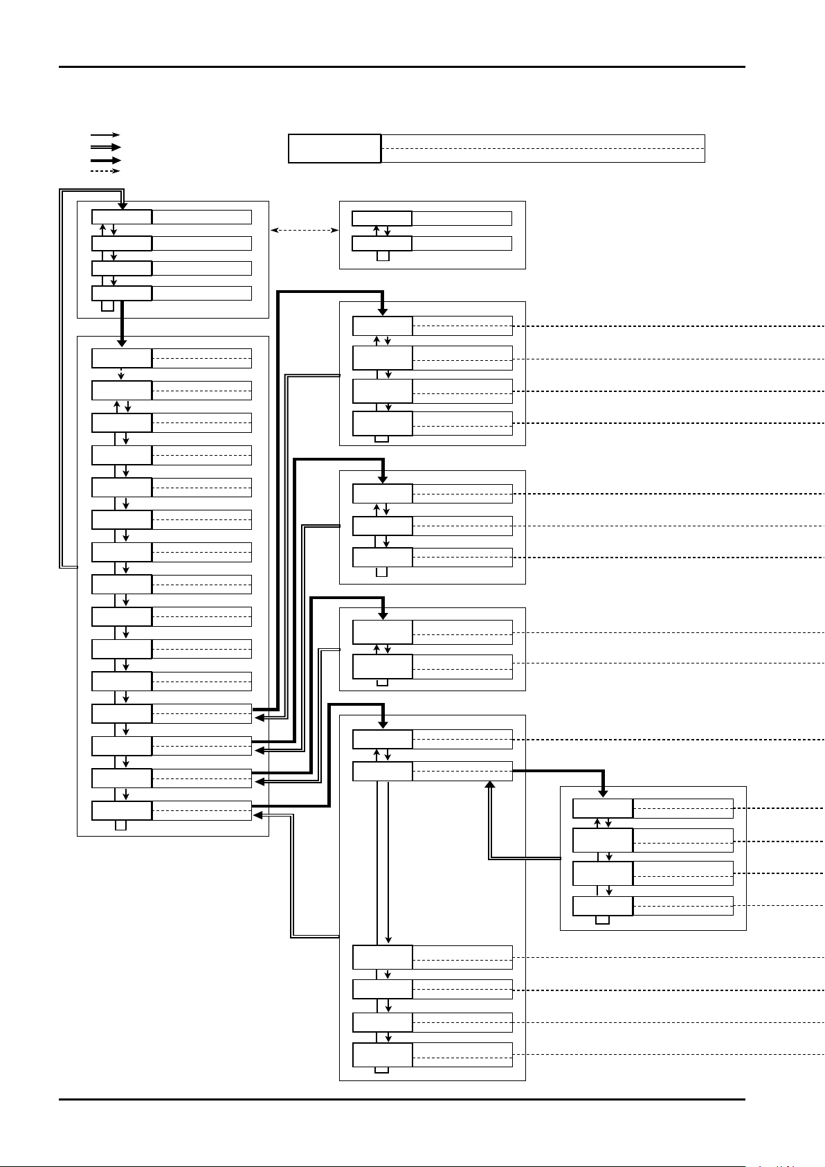
C−102-1-E
Parameter third item
"SEL"
"Press and hold SEL"
"Press and hold ENT"
Other
ENT
Displays instant flow rate
Total flow
Displays % flow rate
Resett able total flow
Displays flow velocity
Setup mode
Circuit voltage monitoring
Coil exciting circuit
error diagnosis
CoiL.S
Set flow parameter 2
F.Prm2
Set flow parameter 3
F.Prm3
Parameter major item
[Top row display] Selects display
[Bottom row display] Displays total flow
Enter password
00-00
01-00
02-00
03-00
04-00
05-00
06-00
07-00
08-00
09-00
10-00
11-00
12-00
13-00
14-00
PAS.wd
11-01
11-02
Set display
dSP.St
Set flow parameter 1
F.Prm1
Set self-diagnosis
diAG.S
Loop test
LP.tSt
Analog output trim function
A.trim
Self-check function
CHECK
Set analog output
A.Out
Set pulse output
P.Out
Set error output
Er.Out
Set alarm
ALArm
12-01
12-02
12-03
Pulse fixed output
LP.PLS
Status fixed output
LP.StS
Analog fixed output
LP.AnA
Set status output
S.Out
Select status output object
St.SEL
Parameter secondary item
Cirt.S
Measurement error
signal diagnosis
11-03
SiGL.S
Empty pipe detection
diagnosis
11-04
Enpy.S
RS485 communication
speed
Polling address
PoL.Ad
14-03
14-04
bAu.br
LCD check
14-05
ALL.on
Maintenance and
calibration mode
14-06
otHEr
Circuit voltage diagnosis
Coil, exciting circuit
diagnosis
Coil.C
14-02-01
14-02-02
Cirt.C
Measurement signal
diagnosis
14-02-03
SiGL.C
Empty detection function
14-02-04
EmPy.C
Analog output 4mA
output adjustment
13-01
Analog output 20mA
output adjustment
13-02
trm.20
trm.04
Self-diagnosis, overall
14-01
Self-diagnosis, individual
14-02
mAnu
Auto
m/s
modE
**.***
*****
*****
**.**
**.**
Parameter name
Layer code (Major item ― Seconda ry item ― Third item)
Parameter
display symbol
12.5 Display Transition (5) Setting Diagnosis and Maintenance Functions
34
Page 35
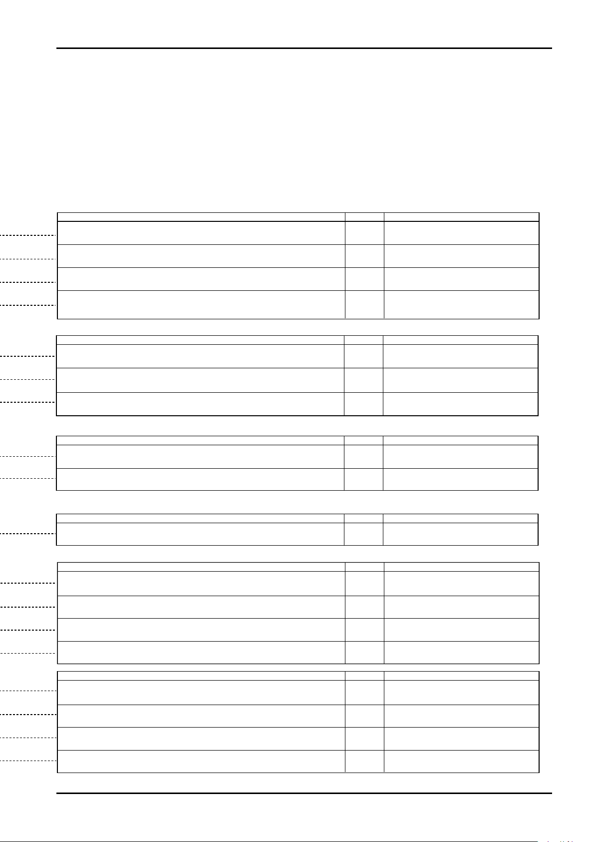
C−102-1-E
Content of parameter Default Setting range
On
On
On
Off
Monitors the current flowing through the coil exciting circuit and diagnoses for abnormality.
* This setting is valid in the auto self-diagnosis in normal measurement.
When diagnosis is started from Menu or through communication, diagnosis is carried out
regardless of this setting.
Diagnoses the circuit voltage in the transmitter.
* This setting is valid in the auto self-diagnosis in normal measurement.
When diagnosis is started from Menu or through communication, diagnosis is carried out
regardless of this setting.
Diagnoses whether or not noise, etc. is superimposed on flow measurement signal.
* This setting is valid in the auto self-diagnosis in normal measurement.
When diagnosis is started from Menu or through communication, diagnosis is carried out
regardless of this setting.
This is set for identifying the instruments when two or more instruments are connected in
multiple points. Set the parameter so that instruments with duplicated address are not present.
In the case of 1 to 1 connection, leave the parameter at "0".
Diagnoses whether or not electrode of probe is wetted and diagnoses the state of error
entry in the pipe under measurement.
* This setting is valid in the auto self-diagnosis in normal measurement.
When diagnosis is started from Menu or through communication, diagnosis is carried out
regardless of this setting.
On, OFF
On, OFF
On, OFF
On, OFF
Content of parameter Default Setting range
Content of parameter Default Setting range
―
19200
0
0 to 63
(2 integer digits)
Not disclosed
―
―
―
―
―
―
―
―
―
―
―
―
―
―
―
―
―
―
―
―
― ―
Content of parameter Default Setting range
Outputs the specified current from analog output.
Outputs pulse of the specified frequency from pulse output.
Outputs the specified level from status output.
Adjusts analog 4mA output.
Adjusts analog 20mA output.
Diagnoses the circuit voltage in the transmitter.
Monitors the current flowing in coil exciting circuit and diagnoses for any
abnormality.
Diagnoses whether or not noise, etc. are superimposed on flow measurement signal.
Diagnoses whether or not the electrode of probe is wetted and judges the
error entry state in the pipe under measurement.
Sets the baud rate of RS-485 communication for setting.
Lights all segments of LCD.
Mode dedicated to OVAL service personnel
Content of parameter Default Setting range
Executes all self-diagnosis items provided and displays the results.
Content of parameter Default Setting range
9600bps,19200bps,38400bps
35
Page 36

C−102-1-E
13. ANALOG OUTPUT FUNCTION
This flowmeter is equipped with analog output function to meet 4-20mA current loop and is able to provide an
output by converting the instant flow rate to analog signal.
It can provide analog output in the desired range with respect to the preset measurement range.
The load resistance of the analog output is 510Ω max. (including cable resistance)
13.1 Setting Analog Output
Analog output setting is available at "A.Out" of the setup menu.
→ Refer to "12.3 Setting Analog Output".
■ Setting 4mA output flow
Sets the flow rate with 4mA output.
■ Setting 20mA output flow
Sets the flow rate with 20mA output.
NOTE: The settable flow rate is in the range that does not exceed the parameter-set measurement range.
■ Time constant at analog output damping
Regulates the variation of analog output. The longer the time constant, the better the output variation is
regulated. However, the response will become slower.
NOTES: 1. Time constant is the time required for the output to reach approx. 63% of the target value.
2. As "Flow measurement damping F.dAmP" of the parameter related to flow rate calculation is set
to 0.5s as standard, the response of actual analog output is the one added by this flow
measurement damping.
■ Analog output low cut
The output is fixed to 4mA until the specified flow rate is reached. It is set by % to the output span.
Low cut (%) = (20mA flow rate - Low cut flow rate) / (20mA flow rate - 4mA flow rate) X 100
Example of analog output: (In case 20L/min is set to 4mA, 29.5L/min to 20mA, and low cut to 10%)
NOTE: As the "Low cut Lo.Cut" of the parameter related to flow calculation is set to 5% as standard, setting
analog output low cut smaller than 5% allows the flow rate of 5% or less is cut in the actual analog
output.
13.2 Analog Output at Error/Alarm
When specific error or alarm (*) occurs during measurement, it can be reported by analog output value.
Up scale : Sets the output current to max. output 20mA + 10% or 21.6mA.
Down scale (standard setting) : Sets the output current to min. output 4mA - 10%, or 2.4mA.
Zero : Sets the output current to 4mA.
Hold : Holds the output (retains the output value just before the occurrence of error
or alarm).
No assignment : Outputs the current in response to the flow instruction regardless of error/
alarm occurrence.
After clearing error/alarm, normal output is restored automatically.
NOTE: * Error/alarm that is generated when normal measurement is not available
→ Refer to "20. ERROR/ALARM STATUS LIST".
36
Page 37
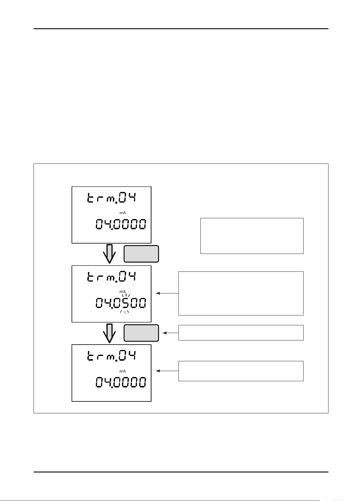
C−102-1-E
Adjustment of 4mA output
SEL : Changes numeral
Press and hold SEL : Cancel
ENT : Shifts digit
Press and hold ENT : Fix
Pressand
holdENT
Pressand
holdENT
The numeral on the bottom row of LCD blinks
and 4mA is output from the transmitter.
Enter the ammeter reading at this time in the
same way as that of normal parameter setting.
Confirm the entry by "Press and hold ENT".
When the entry is confirmed, 4mA after
adjustment is output.
13.3 Adjusting Analog Output
The current of analog output has been adjusted at the time of factory shipment. If, however, any error is present
in the output value and measurement value depending on your service environment, adjustment of the current
of analog output is available.
Analog output adjustment begins from "A.trim" of Setup mode.
■ Preparation for adjustment
Connect the ammeter to the analog current loop in series.
(Using the current monitoring function of the connected measurement, control instrument, etc. are also
permitted.)
Be careful not to cause unexpected operation of external instrument due to variation of current.
■ Adjustment of 4mA output
Enter the adjustment mode from "trm.04" (layer code 13-01) of "A.trim" submenu in the Setup mode.
Perform adjustment for 20mA from the menu "trm.20" in the same manner.
After setting, "Press and hold SEL" from the Menu to return to "A.trim" display. Then simulative output is
cleared and normal output state is restored. (Simulative output continues in the "A.trim" submenu.)
37
Page 38
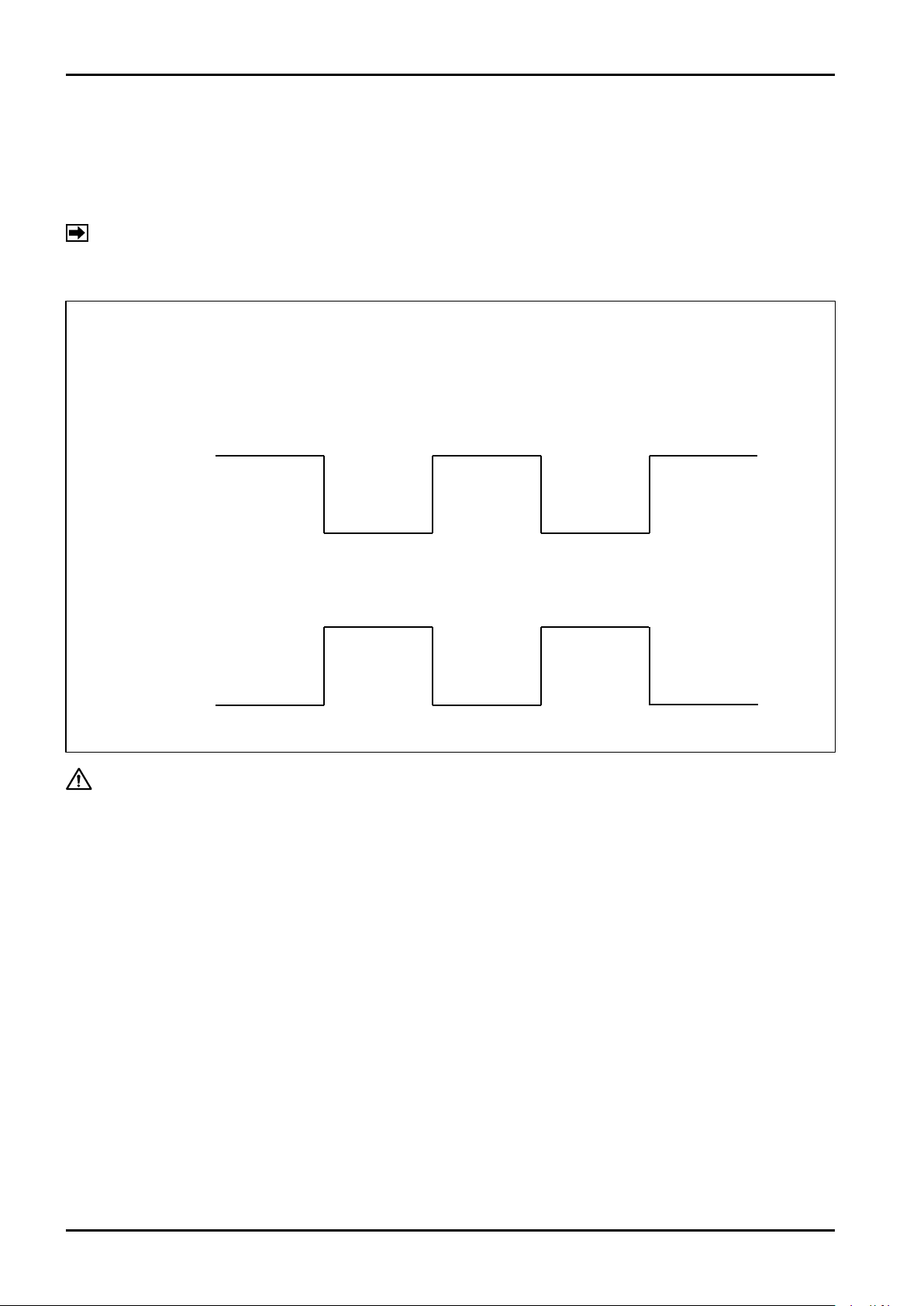
C−102-1-E
Output pulse waveform
Open drain pulse output
Voltage pulse output
* Under 1Hz, ON width is fixed at 500ms.
ON
ON
Open
Close
ON
ON
Lo
Hi
Pulse width Duty ratio 50% (*)
14. PULSE OUTPUT AND TOTALIZING FUNCTION
This flowmeter is equipped with pulse output function. It can output factored pulse to which weight per pulse is
added in advance or pulse with a frequency proportional to the flow rate.
Frequency pulse is an open drain pulse in the range of 0.01 to 11kHz or 18V voltage pulse (depending on
delivery specifications).
NOTE: Voltage pulse has a configuration where 18V is applied to the drain terminal in the transmitter.
As current regulating resistance of 2.2kΩ is added, the output voltage at ON decreases in proportion
to the current output.
CAUTION: The maximum capacity of open drain pulse output terminal is 30V/50mA. An
entry exceeding this rating may result in the failure of the transmitter.
14.1 Setting Pulse Output
Pulse output setting is performed from the "P.Out" submenu of the Setup menu.
■ Setting pulse output mode
Sets the function of the pulse output.
Either frequency pulse mode or factored pulse mode (weighted pulse) can be selected.
Pulse calculation mode setting is carried out from "P.Out" → "P.modE" of the Setup menu.
Frequency pulse mode
Output frequency is determined by using frequency factor and the flow rate at a certain point.
The output frequency is determined by the following formula.
Output frequency (Hz) = Frequency factor (Hz) X Instant flow rate / Flow factor
The flow rate (weighting) per pulse is determined by the following formula (when instant flow rate unit is
L/min).
Pulse weighting (L/P) = Flow rate factor (L/min) / 60 / Frequency factor (Hz)
Fig. 14.1
38
Page 39
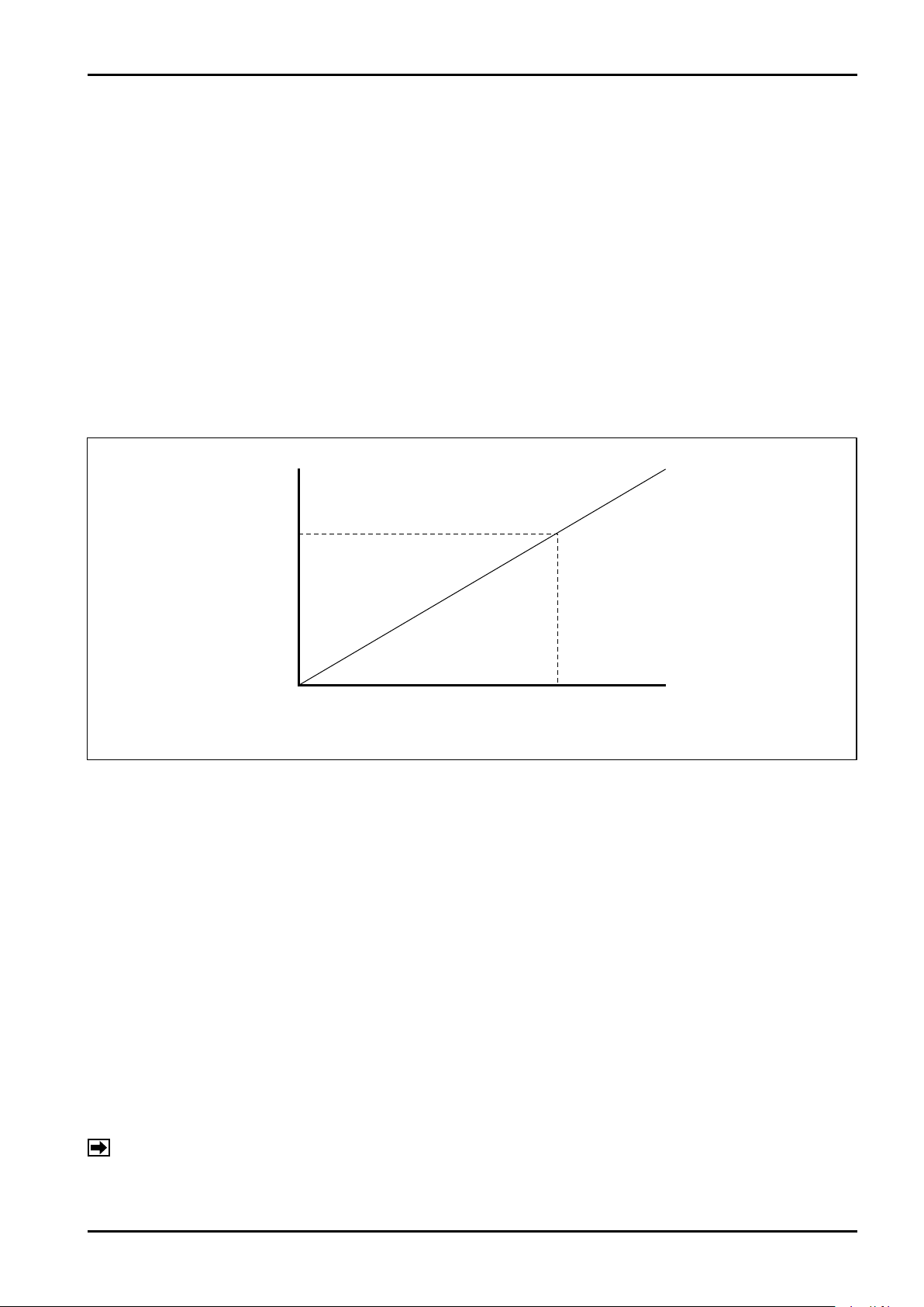
C−102-1-E
Max.11kHz
Frequency factor
Flow rate factor
Instant flow rate
Pulse output frequency
Factored pulse mode
In this method, flow rate per pulse is specified.
This mode is used when pulse output is entered to the total counter, etc.
The output frequency is determined by the following formula (when instant flow rate unit is L/min and total
flow unit is L).
Output frequency (Hz) = Instant flow rate (L/min) / 60 / Pulse weighting (L/P)
Set the output frequency so that at the time of maximum flow is 10kHz or less.
Frequency exceeding 11kHz cannot be output.
■ Setting frequency factor (Set in the case of frequency pulse mode)
Th e frequ ency to be output when ins tant flo w rate reache s the flo w facto r setti ng valu e. (10Hz
(recommended) to 10kHz)
■ Setting flow rate factor (Set in the case of frequency pulse mode)
Set the flow rate for outputting the frequency factor set value.
(Frequency pulse mode setting image)
■ Setting pulse weighting (Set in the case of factored pulse mode)
Set the flow rate per pulse.
14.2 Pulse Output at Error/Alarm
This function is to report a specific error or alarm (*) that arises during measurement by means of pulse output
frequency.
Pulse output is changed to one of the following specific frequencies.
Zero (standard setting) : Stops pulse output (0Hz).
Hold : Continues outputting the frequency just before the occurrence of error/alarm.
Up scale : Outputs the pulse frequency corresponding to the flow rate where instant flow rate
No assignment : Outputs the frequency corresponding to the instant flow rate indication regardless
After clearing error/alarm, normal output restores automatically.
NOTE: * For the error/alarm that occurs when normal measurement becomes unavailable, refer to "20.
Fig. 14.2
is 110% of the measurement range.
of the occurrence of error/alarm.
ERROR/ALARM STATUS LIST".
39
Page 40

C−102-1-E
(On・Active)
(Normal) (Alarm occurrence) (Normal recovery)
(Normal) (Alarm occurrence) (Normal recovery)
Transistor
OFF
Transistor
ON
(Off・Active)
Transistor
OFF
Transistor
ON
15. STATUS OUTPUT FUNCTION
This flowmeter has a status output function that can output error/alarm and status information.
Status output is open collector output.
15.1 Selecting Status Output
■ Allocating status output
Sets the function allocated for status output.
Setting is selectable from no allocation, error/alarm output, high-low alarm output, or flow direction.
Error/alarm detection is selected from "Er.Out" of the Setup menu and the higher/lower limit alarm output
setting is selected from "ALArm" of the Setup menu. (Refer to "20. ERROR/ALARM STATUS LIST".)
■ Status output mode
Sets the mode (logic) of status output.
Setting is selectable from Off・Active (transistor ON normally, OFF at output) and On・Active (transistor OFF
normally, ON at output).
Fig. 15.1
15.2 High/Low Limit Alarm Function
This is a function to report as alarm when flow rate indication exceeds the preset range. The high/low limit alarm
is validated when status output is allocated to the high/low limit alarm. The setting related to the high/low limit
alarm is carried out from the "ALArm" submenu of the Setup menu.
■ High alarm point and low alarm point
Sets the threshold level of the flow rate. If the flow rate exceeds the higher limit or goes below the lower limit,
an alarm is generated.
■ Alarm hysteresis
In order to prevent chattering at the flow rate nearby the high limit or low limit, providing hysteresis is
available.
When the flow rate exceeds the high alarm point, reducing the flow rate goes down to High alarm point
setting - Hysteresis setting allows the alarm to be cleared. When the flow rate goes below the low alarm
point, increasing the flow rate up to Low alarm point setting + Hysteresis setting allows the alarm to be
cleared.
15.3 Flow Direction Output Function
Output corresponds to the sign of flow direction.
In the case of reverse flow (when instant flow rate indicated on LCD display shows negative value), active
output is generated.
40
Page 41
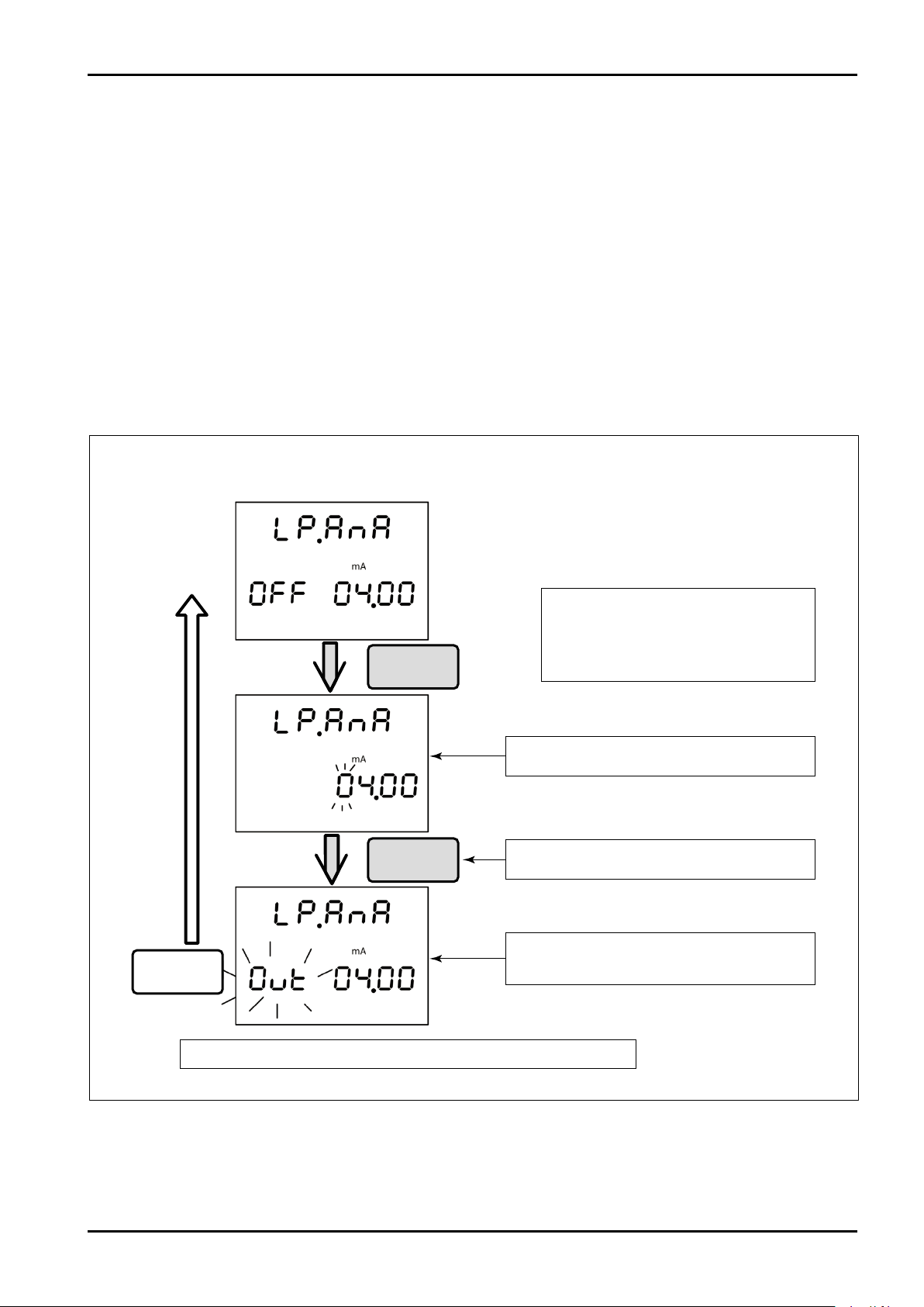
C−102-1-E
Simulative output (Analog output)
SEL : Changes numeral
Press and hold SEL : Cancel
ENT : Shifts digit
Press and hold ENT : Fix
Confirm the entry by "Press and hold ENT".
After Confirmation, "Out" blinks and the set
current is output.
"Press and hold SEL" stops output and returns to the original screen.
Set the current value of output.
Pressand
holdENT
Pressand
holdENT
Pressand
holdSEL
16. LOOP TEST (SIMULATIVE OUTPUT) FUNCTION
With this function, simulative output of analog, pulse and status is carried out for verifying the connection
between this flowmeter and external instruments. The loop test is operated from the "LP.tSt" submenu under
the Setup mode.
■ Analog simulative output
Outputs a desired current (2.4mA to 21.6mA) from the analog output terminal.
■ Pulse simulative output
Outputs a pulse of desired frequency from the pulse output terminal.
■ Status simulative output
Outputs ON or OFF from the status output terminal simulatively.
16.1 Simulative Output Operation
Select the item to be output simulatively from the "LP.tSt" submenu of the Setup menu.
Both pulse and status simultative output operations can be performed by the same procedure.
When 10 minutes pass without any key operation during output operation, output stops and the Measure mode
is restored.
41
Page 42
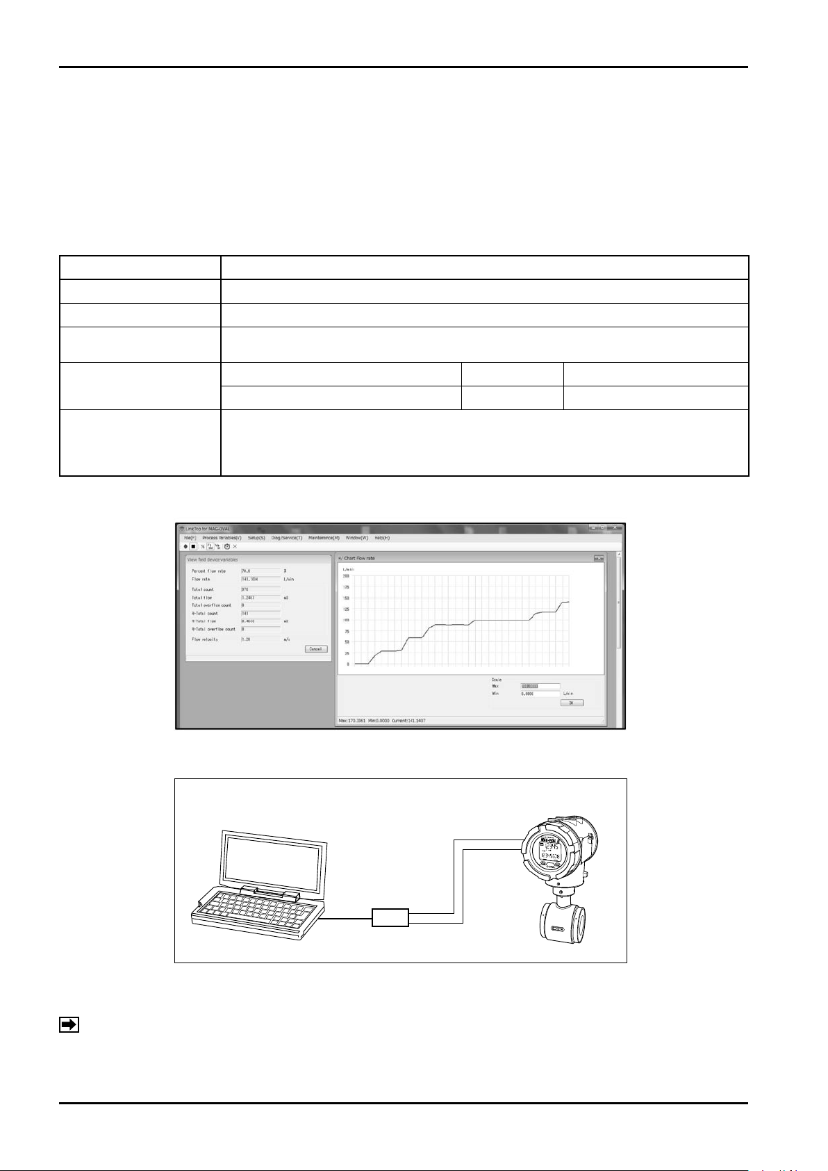
C−102-1-E
ERR.
ALM.
PC with communication software installed
(*1)
RS-485
communication
interface
MAG-OVAL III
output signal
terminal
RS-485
+
+
−
−
17. COMMUNICATION FUNCTION
This flowmeter is capable of monitoring measurement value, logging and saving of instant flow rate in CSV
format. In addition, changing, saving, etc. of parameters locally or remotely is available by the use of dedicated
communication software "LinkTop for MAG-OVAL" to be purchased separately. For the handling of the
communication software, refer to the instruction manual of "LinkTop for MAG-OVAL".
17.1 Communication Specifications
■ Specifications (Communication software "LinkTop for MAG-OVAL")
Item Specifications
Physical layer
RS485 (*1), Bell202 (Bell202 communication spec. for MAG-OVAL III is supported specifically.)
Communication system Master slave system
Communication baud rate
RS485 communication : 9600, 19200, 38400bps
Bell202 : Fixed at 1200bps
Supporting OS Memory (RAM) Hard disk
Operating environment
Windows XP, Windows Vista, Windows 7 256MB or more Free space of 10MB or more
・ Monitoring of measurement value (Numeral display, graphic display)
Functions
・ Logging and saving of instant flow rate, % flow rate, flow velocity
(Storage format: CSV file, Logging period: 0.2 sec. to 1 hour) (*2)
・ Reading, setting change, saving of parameter
■ Example of display screen of communication software
■ Connection with personal computer
As the flowmeter has no built-in terminating resistor, attach a terminating resistor of 120Ω/0.5W at the line
terminating section.
NOTES: *1: RS485 communication interface is not supplied with the flowmeter. Use the RS485-USB
*2: As communication baud rate is low with the Bell202 communication spec., the shortest logging
42
converting adapter available on the market.
period is 1 second.
Fig. 17.1
Fig. 17.2
Page 43

C−102-1-E
17.2 Setting Communication Functions
Setting of communication functions is carried out in the CHECK submenu under the Setup menu.
■ Setting baud rate
Baud rate is set from "bAud.r" of the CHECK submenu under the Setup menu. It can be selected from
9600bps, 19200bps, or 38400bps.
→ Refer to "12.5 Display Transition (5) Setting Diagnosis and Maintenance Functions".
■ Setting polling address
Polling address is set from "P.Addr" of the CHECK submenu.
→ Refer to "12.5 Display Transition (5) Setting Diagnosis and Maintenance Functions".
Polling address is set for identifying the instrument when two or more instruments are connected at the
multiple points on the same communication line. Be sure to set the polling address so that no instruments of
the same address exists on the same communication line. In the case of 1 to 1 connection, use the default
value (0).
43
Page 44

C−102-1-E
18. SELF-DIAGNOSIS FUNCTION
This flowmeter is equipped with self-diagnosis function. Use this function for early detection of abnormality,
troubleshooting, etc.
Flow measurement can continue even during self-diagnosis operation. Diagnosis can be executed periodically
even normal measurement is in operation. This function reports an error or alarm if any abnormality is found.
Self-diagnosis can be operated automatically or manually from the Setup menu.
Regarding the self-diagnosis during normal measurement, valid or invalid can be switched per item through
self-diagnosis setting.
In the case of diagnosis being operated by manual operation, diagnosis is implemented instead of selfdiagnosis setting.
→ Refer to "12.5 Display Transition (5) Setting Diagnosis and Maintenance Functions".
18.1 Self-diagnosis Items
■ Circuit voltage measurement
Measures voltages in the transmitter circuits. If the voltage is out of the specified range, normal measurement
may not be performed. If diagnosis shows abnormality, contact your nearest sales office or service center.
■ Coil and exciting circuit abnormality diagnosis
Checks for any abnormality in the coil or exciting circuit of the probe. If the measurement value is outside the
specified range, exact measurement may not be performed.
If diagnosis shows abnormality, contact your nearest sales office or service center.
■ Empty detection diagnosis
Checks whether the electrode of the probe is wetted or not. As this flowmeter is based on the assumption that
the pipe measured is filled completely, exact measurement may not be achieved with empty pipe. If abnormality
judgment occurs, make sure the pipe is full of fluid. If abnormality judgment occurs regardless of the full state of
pipe, abnormality in the probe or transmitter is suspected. Contact your nearest sales office or service center.
NOTE: Empty detection may not function if inside the probe is wetted.
■ Measurement error signal diagnosis
Investigates whether or not the measurement signal level inside the transmitter is within the specified range.
Typically, when noise is superimposed on the measurement signal due to poor grounding, abnormality judgment
will occur.
NOTE: Make sure grounding is correct in accordance with grounding procedure. If the abnormality is not
cleared even after the inspection of grounding, contact your nearest sales office or service center.
44
Page 45
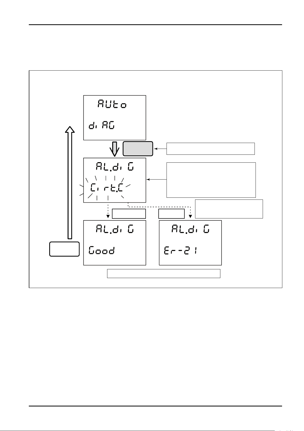
18.2 Diagnosing All Items
Started by "Press and hold ENT".
Ex. Er-21
Abnormality found in
coil, exciting circuit
"Press and hold SEL" returns to the original screen.
The screen during self-diagnosis.
An item in self-diagnosis operation is
indicated on the bottom row of LCD.
Display changes in the sequence of
Cirt.C → CoiL.C → SiGL.C → EnnPy.C.
Self-diagnosis menu
Pressand
holdENT
Pressand
holdSEL
No abnormality
Abnormal
This function executes self-diagnosis of all four items and displays the results.
This function is activated by self-check function "CHECK" of the Setup mode (layer code 14-00).
C−102-1-E
When diagnosis is completed, the results are displayed. If no abnormality is found, "Good" is displayed. If
abnormality is found in any of diagnosis items, error or alarm No. of the corresponding item is displayed.
For the details of error/alarm, refer to "20. ERROR/ALARM STATUS LIST".
45
Page 46
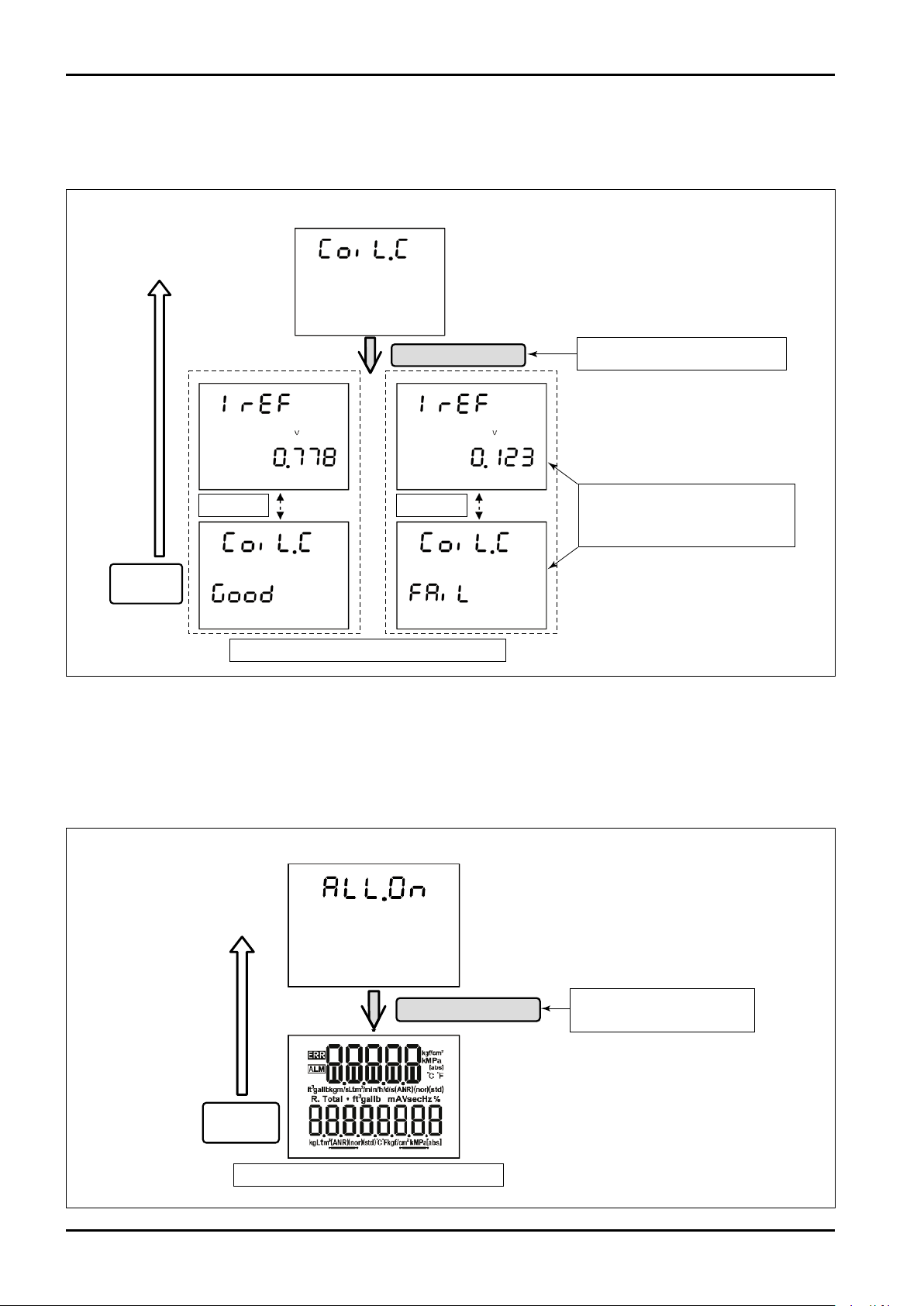
C−102-1-E
PressandholdENT
Pressand
holdSEL
Started by "Press and hold ENT".
Measurement value and judgment
result are displayed alternately at
certain intervals.
Coil, exciting circuit abnormality diagnosis
No abnormality
Abnormal
"Press and hold SEL" restores original screen.
PressandholdENT
Pressand
holdSEL
"Press and hold ENT" lights all
displays on the LCD.
LCD CHECK
"Press and hold SEL" restores original screen.
18.3 Diagnosing Self-diagnosis Items Individually
Individual self-diagnosis item can be selected from the menu by entering "mAnU" submenu under "CHECK"
submenu.
If no abnormality is found, "Good" is displayed. If abnormality is found, "FAiL" is displayed.
If any abnormality is present, please inform OVAL of the abnormal item with the measurement value for quick
study of cause and countermeasure.
19. LCD CHECK
This function displays all segments of LCD for verifying the soundness of the display.
46
Page 47
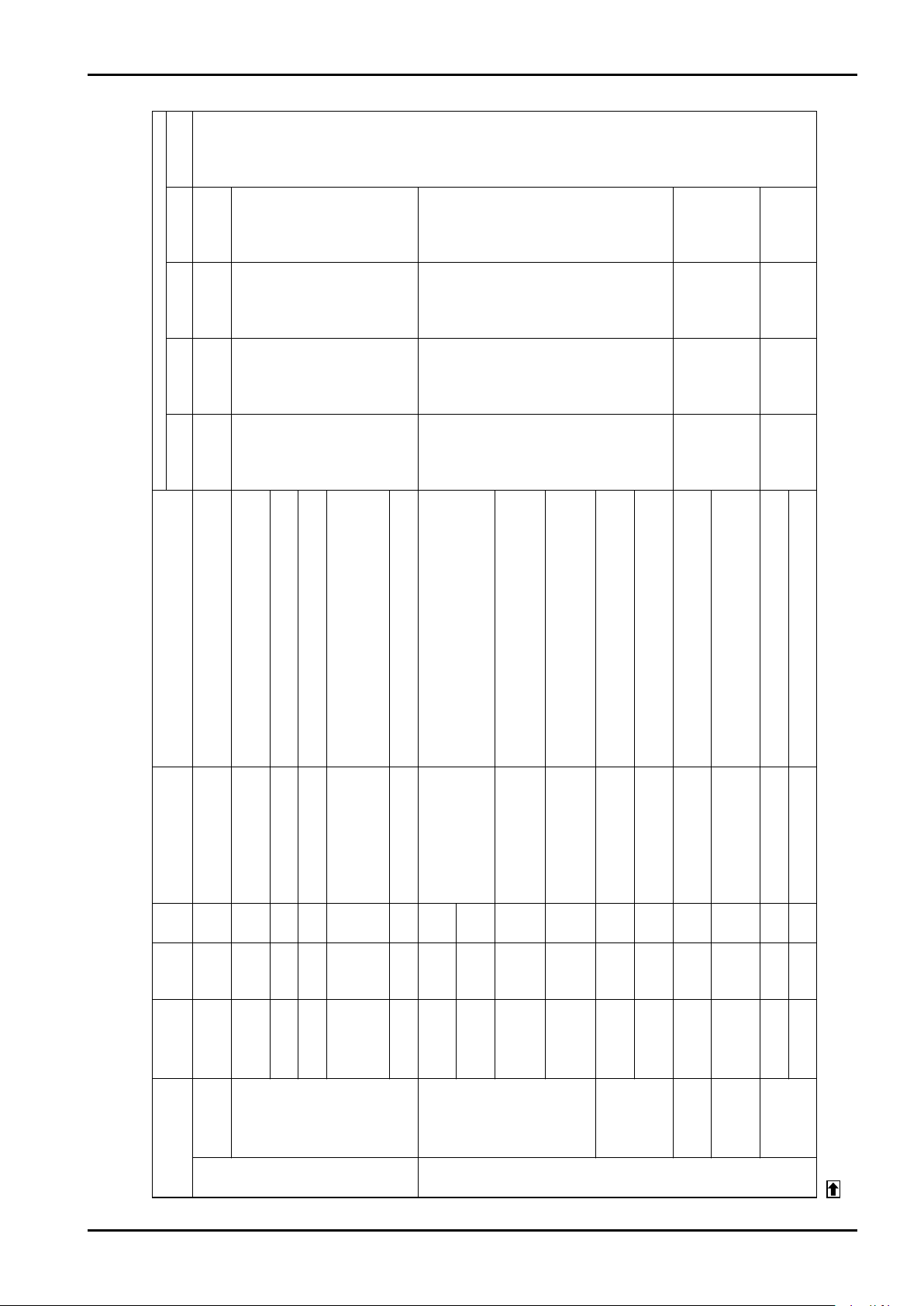
C−102-1-E
(S.Out)
setting and
Depends on
status output
(St.SEL)
status output
item selection
or equiv.
Output with
flow rate 110%
(21.6mA)
Output 110%
Analog output Pulse output Status output
Display/Output
display
Total flow
Instant flow rate
or equiv.
Totalized with
flow rate 110%
display
or equiv.
displayed
Flow rate 110%
At the
occurrence of
At the
occurrence of
setting.
error, output is
output (Er.PLS)
subject to pulse
setting.
(Er.ANA)
subject to
analog output
error, output is
Stopped (0%) Not totalized
output
Normal
measurement
output
Normal
measurement
Normal
totalizing
operation
displayed
flow rate is
Normal instant
At the
occurrence of
At the
occurrence of
setting.
error, output is
output (Er.PLS)
subject to pulse
setting.
(Er.ANA)
subject to
analog output
error, output is
Stopped (0%) Not totalized
output
Normal
measurement
output
Normal
measurement
Normal
totalizing
operation
displayed
flow rate is
Normal instant
Set hysteresis value equal to or lower than the difference
Adjust flow so that % flow rate is less than 110% or increase
the setting of the measurement range.
Disconnection of exciting coil or transmitter failure (*2)
Trouble in data input to FRAM (memory) or faulty part (*2)
Failure in data communication with built-in CPU or faulty part
(*2)
Fault in probe or transmitter (*2)
Faulty transmitter (*2)
Set the measurement range within 0.5 to 10m/s in
conversion to flow velocity.
Analog output setting exceeds the limit. Set the output to the
value within the limit.
→ See "13. ANALOG OUTPUT FUNCTION".
Flow rate exceeds 110% of
measurement range.
Abnormality in probe exciting
coil or transmitter exciting
circuit (*1)
Abnormal data written in
FRAM (memory)
Abnormal update of internal
data
Transmitter amp.
compensation standard is
not appropriate and normal
flow rate calculation is not
available.
Abnormal circuit voltage in
transmitter *1
State where abnormality is
present in the setting of
measurement range.
Entered analog output high/
low limit alarm point setting
is not appropriate (exceeding
the limit).
CoiL.Cir Er-21
error
Coil excitation
Overflow error Overflow error OvEr.FLo Er-11
Category Error name Message Code Description Cause and Countermeasure
20. ERROR/ALARM STATUS LIST
20.1 Error/Alarm List
dAtA.updt Er-23
error
Amplifier
Internal data
Memory error PArA.FrA Er-22
Hardware
abnormal error
Error
Cir.voLt Er-25
HArd.Ap Er-24
hardware error
SEt.FL.Hi AL-31
SEt.FL.Lo AL-32
SEt.A.Out AL-33
error
range higher
Measurement
Circuit voltage
alarm
limit alarm
Measurement
range lower limit
alarm
Analog setting
alarm
Parameter
between High alarm and Low alarm points
Adjust the flow so that analog output is in the range of 4 to
20mA or change the high/low limit of analog output.
Adjust the flow so that pulse output frequency is 10kHz or
less or change the pulse weight or frequency factor to the
appropriate value.
Fault is present in the measurement signal of transmitter.
Verify that flowmeter is grounded correctly or no object is
adhered on the electrode of the probe.
Perform air bleeding of the pipe under measurement and
always keep the pipe filled with liquid.
Adjust the flow to be lower than High alarm point or increase
the setting of High alarm point.
Adjust the flow to be higher than Low alarm point or
・Set High alarm point below measurement range setting
・Set Low alarm point below High alarm point
・
Entered alarm point setting is
not appropriate (exceeding
the limit).
Analog output reached the
low limit of 2.4mA or high
limit of 21.6mA.
Pulse output frequency
reached the high limit of
11kHz.
Abnormal transmitter
measurement signal (*1)
Pipe under measurement is
not filled with liquid
(electrode is exposed). *1
AL-41
SEt.ALAr AL-34
setting alarm
High/Low point
P.Out.SAtu AL-42
A.Out.SAtu
Pulse output
Analog output
saturation alarm
Output
saturation
Alarm
Measurement
saturation alarm
alarm
Measurement
E.PiPE AL-44
SiG.QuAL AL-43
alarm
signal alarm
Empty detection
alarm
alarm
signal abnormal
Empty detection
decrease the setting of Low alarm point.
Low limit alarm F.r.Lo AL-46 Low limit alarm occurring
High limit alarm F.r.Hi AL-45 High limit alarm occurring
alarm
High/Low limit
*2: If rebooting does not clear the trouble, contact OVAL representative you purchased the product, your nearest OVAL sales office, or service center.
NOTES: *1: Occurs when self-diagnosis setting is valid. Refer to "12.5 Display Transition (5) Setting Diagnosis and Maintenance Functions".
47
Page 48
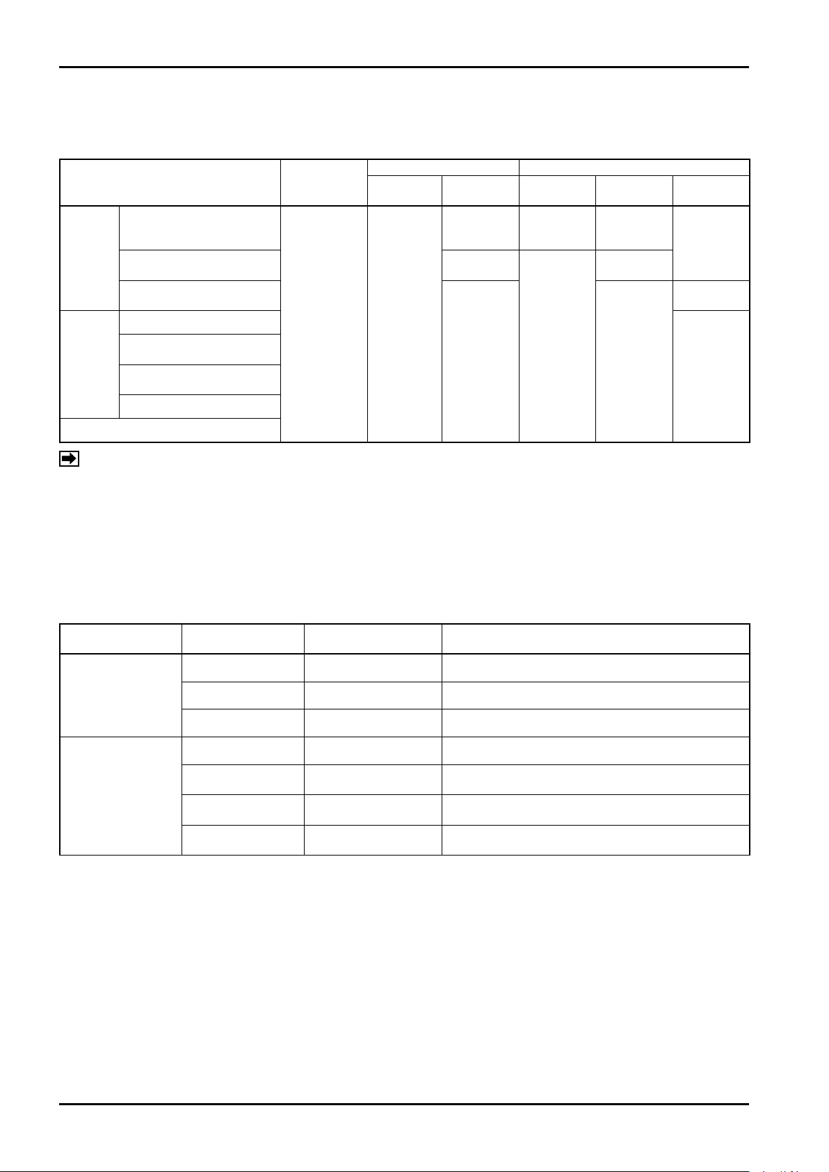
C−102-1-E
20.2 Other Statuses
About measurement and output in individual status
Display status (*) Output operation
Instant flow
rate
Normal
display
Total flow
Normal
totalizing
operation
Totalization
stopped
Normal
totalizing
operation
Analog
output
Simulating
output
Normal
measurement
output
Pulse output Status output
Normal
measurement
output
Simulating
output
Normal
measurement
output
Depends on
output
setting
Simulating
output
Depends on
output
setting
Loop test
Self-
diagnosis
Status
In analog simulating output
In pulse simulating output
In status simulating output
In circuit voltage monitoring
In coil exciting circuit
abnormality diagnosis
In measurement error signal
diagnosis
In empty detection diagnosis
In other mode display
Measurement
status
Normal
measurement
NOTE: * Even during loop test (simulating output), flow display shows actual flow rate measured.
About status display during external operation through communication
When special operation or processing is executed through communication (at the execution of individual
functions, etc.), the following message or code is displayed on the LCD display of the transmitter.
When the operation is stopped or cleared, the message will disappear.
Status Display
Status category
Simulating output
Self-diagnosis
Message displayed
on transmitter
A.Out.Fi St-60 Simulating output of analog output is in process.
P.Out.Fi St-61 Simulating output of pulse output is in process.
S.Out.Fi St-62 Simulating output of status output is in process.
SELF.d.VoL St-70 Self-diagnosis-circuit voltage diagnosis is in process.
SELF.d.CoI St-71
SELF.d.SiG St-72
SELF.d.PiP St-73
Error is a state where setting is inappropriate or normal flow measurement is not available due to occurrence of
significant problem. Alarm is a state where measurement is executed but output or display is not available
normally. Status is to report the specific processing or operation (self-diagnosis, etc.) is in process through
communication (not affecting the measurement).
Status code displayed
on transmitter
Description
Self-diagnosis-exciting coil, exciting circuit diagnosis
is in process.
Self-diagnosis-measurement signal diagnosis is in
process.
Self-diagnosis-measurement pipe empty detecting
function is in process.
48
Page 49
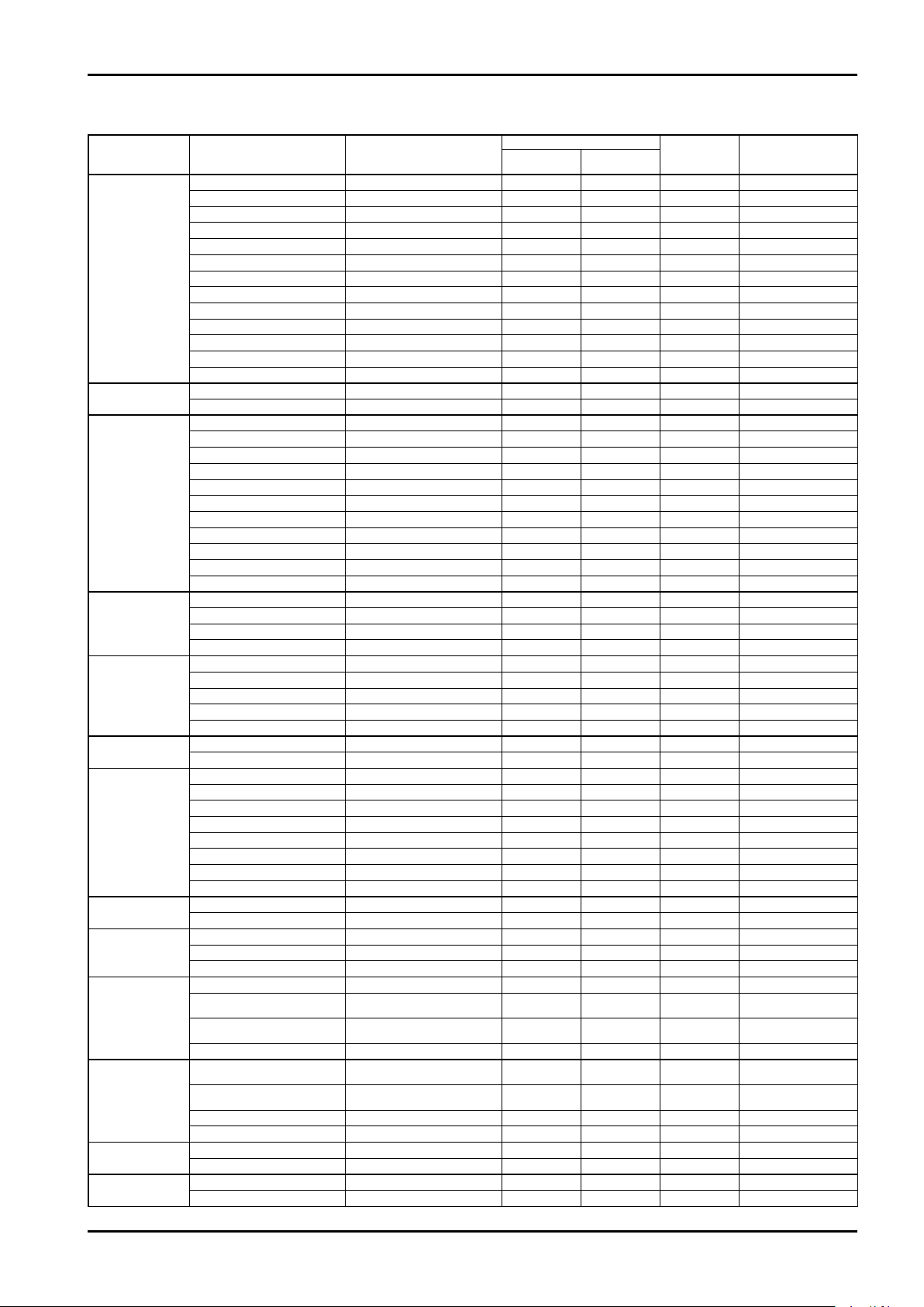
21. PARAMETER LIST
Major item Item on parameter sheet Parameter name
Device (transmitter)
information
Flow parameter
Transmitter setting
(Field device
variable)
Analog output
Pulse output
Status output
Status output item
selection
(Status output
select)
Error output
High/Low alarm
(H/L alarm)
Self-diagnosis
(Self diag)
Display setting
Security
Analog adjustment
(Trim Analog)
Tag
Descriptor
Message
Date
Device ID
Sensor serial No.
Final assembly No.
Flange type
Flange material
Liner material
Electrode type
Electrode material
Hardware rev
Nominal diameter
Flow range
Flow rate unit
Total flow unit
Flow damp
Low cut
Low cut hys
I.F. suppress factor
Calibration zero
Calibration factor
Auto gain compensation
Flow direction
Conversion factor
Upper range value
Lower range value
Analog Low cut
Analog Damp
Pulse operation mode
Freq factor
Rate factor
Low cut
Pulse weight
Status output function
Status output mode
Overflow error
Hardware failure
Parameter alarm
Saturated alarm
Measurement signal alarm
Empty pipe alarm
Fixed output
Self diag in progress
Analog error output
Pulse error output
High alarm point
Low alarm point
H/L alarm hys
Circuit voltage
Exciting coil/circuit
Measurement signal
Empty pipe
Flow rate decimal
Total flow decimal
Variables display cycle
Back light set
Password option
Setting password
4mA adjust value
20mA adjust value
Tag number
Descriptor
Message
Date of manufacture
Device ID
Sensor serial No.
Serial No.
Flange rating
Flange material
Liner material
Electrode type
Electrode material
Hardware revision
Nominal diameter
Measurement range
Instant flow rate unit
Total flow unit
Flow measurement damp
Low cut
Low cut hysteresis
Noise trouble suppression
Zero point
Calibration factor
Auto gain compensation
Flow direction
Fixed conversion factor
Analog output upper limit flow
Analog output lower limit flow
Analog output low cut
Analog output damping
Pulse operation mode
Frequency factor
Flow rate factor
Pulse output low cut
Pulse weight
Status output function
Status output mode
Overflow error
Hardware failure
Parameter alarm
Output saturation alarm
Measurement error signal alarm
Empty pipe detection alarm
Simulating output state
Self-diagnosis in process
Analog output at error
Pulse output at error
High alarm point
Low alarm point
High/Low alarm hysteresis
Circuit voltage monitoring
Coil exciting circuit abnormality
diagnosis
Measurement error signal
diagnosis
Empty detection diagnosis
No. of instant flow rate digits
below decimal point
No. of total flow digits below
decimal point
Screen display update cycle
Back light setting
Password function setting
Setting password
4mA adjust value Factory set
20mA adjust value Factory set
C−102-1-E
Reference/setting on display
Reference to
setting
○ 04−02
○ ○ 02−01
○ ○ 01−02−01
○ ○ 01−02−03
○ ○ 02−02 0.50sec
○ ○ 02−03 5 %
○ ○ 02−04 OFF
○ ○ 03−01 OFF
○ 04−03
○ 04−04
○ ○ 03−02 OFF
○ ○ 03−03 Positive Flow
○ ○ 02−05 1.0000
○ ○ 05−02
○ ○ 05−01 00000E0
○ ○ 05−04 0.0 %
○ ○ 05−03 0.0 sec
○ ○ 06−01
○ ○ 06−02
○ ○ 06−03
○ ○ 06−04
○ ○ 06−05
○ ○ 07−01 No Function
○ ○ 07−02 On Active
○ ○ 08−01 OFF
○ ○ 08−02 OFF
○ ○ 08−03 OFF
○ ○ 08−04 OFF
○ ○ 08−05 OFF
○ ○ 08−06 OFF
○ ○ 08−07 OFF
○ ○ 08−08 OFF
○ ○ 09−01 Downscale
○ ○ 09−02 Zero
○ ○ 10−01 0.0000E0
○ ○ 10−02 0.0000E0
○ ○ 10−03 0.0000E0
○ ○ 11−01 ON
○ ○ 11−02 ON
○ ○ 11−03
○ ○ 11−04 ON
○ ○ 01−02−02
○ ○ 01−02−04
○ ○ 01−04 500ms
○ ○ 01−03 Auto
○ ○ 01−01−01 OFF
○ ○ 01−01−02 0000
Setting change
Layer code of
display
transition table
Subject to measurement
Subject to measurement
Default
As specified
As specified
As specified
As specified
Factory set
Factory set
As specified
As specified
As specified
As specified
As specified
As specified
OFF
range
range
49
Page 50
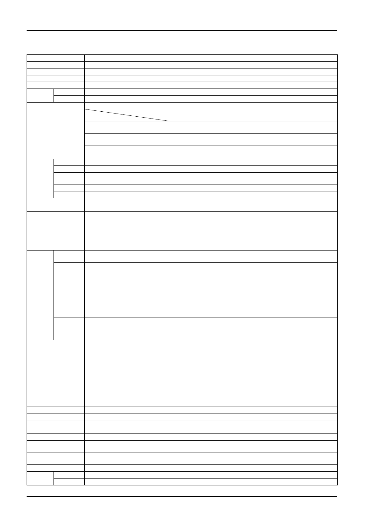
C−102-1-E
22. GENERAL SPECIFICATIONS
Item Description
Nominal size (mm) 3, 6, 10, 15 25, 40, 50, 80, 100 150
Connection Screw-in type (G male thread) Wafer type (Sandwich design for installation between flanges)
Applicable liquids Liquids (water, industrial water, slurries, chemical liquids, solutions) * Only conductive liquids
Flow range See the table on the next page.
Operating
temp. range
Max. operating pressure Depending on connection standard (Max. allowable pressure for flowmeter: 2.94MPa)
Accuracy
Repeatability ±0.1% of full scale
Materials
Excitation A square wave excitation is used.
Minimum conductivity 10μS/cm
Display
(LCD digital display)
Output
Alarm/Error
detecting function
Communication function
Power supply AC spec.: 85 to 264VAC 50Hz, 60Hz or DC spec.: 20 to 30VDC (to be selected)
Power consumption 20VA max.
Cable entry G1/2 X 2 places
Power cord Shielded cable for general instrumentation 1.25mm2 or less
Mounting structure Probe and transmitter built in one (Nominal size 3, 6mm is to fix the transmitter using dedicated mounting bracket)
Straight pipe length
required
Physical orientation
Enclosure protection Dust tight/watertight enclosure: IP66 Explosionproof rating: Non-explosionproof
Finish
Fluid -10 to +130°C
Ambient -20 to +60°C
Nominal size
* In case of analog output, ±0.2% of full scale is added.
Probe Flow tube: Stainless steel (SUS304 or equiv.) Probe housing: Steel plate
Lining Fluorocarbon polymers (PFA) Fluorocarbon polymers (PTFE)
Electrodes
Earth electrode
Transmitter Aluminum die-cast
Analog
Pulse
Status
Probe Phthalate resin finish Color: Munsell N1.5 (black)
Transmitter Baked melamine finish Color: Body: Munsell 10B8/4 (Light blue) Lid: Munsell 2.5PB4/10 (Blue)
・SUS316L ・Alloy C276 (equiv. to Hastelloy C)
・Tantalum ・Platinum
Same as electrode SUS316 (Earth ring system)
・5 digits of 8 segments + 8 digits of 7 segments + Unit indicator (with backlight)
・Top row (5 digits): (1) Instant flow rate
(2) % instant flow rate Switching among these items is available with a selector magnet.
(3) Flow velocity Unit of flow rate can also be selected by parameter setting.
・Bottom row (8 digits): (1) Total flow (Display can be rotated by 90° steps over 360°.)
(2) Resettable total flow
・Operation switch (magnet switch type): 2 pieces
4 to 20mA Load resistance 510Ωmax.
Operation at the occurrence of abnormality: Down scale 2.4mA (default)
・Signal form: Either open drain pulse output or voltage pulse output is selected.
(1) Open drain pulse output Capacity: 30VDC 50mA max. ON resistance 1Ω max.
(2) Voltage pulse output Low level: 1.5VDC max., High level: 15VDC min, Output impedance: 2.2kΩ
・Pulse type: Either factored pulse or frequency pulse is selected.
(1) Factored pulse Pulse frequency: 0.01 to 10000Hz
Pulse width: Pulse width changes as follows in accordance with the frequency of
In case Pulse frequency > 1Hz : Pulse ON/OFF duty ratio 50 to 50
In case Pulse frequency ≦ 1Hz : Pulse ON width fixed at 500ms
(2) Frequency pulse Upper limit frequency: 10000Hz
・Signal form: Open collector output
Capacity: 30VDC 50mA max. Voltage at ON: 1.5VDC max.
One among alarm/error detection, forward/backward flow direction, and upper/lower limit alarm is selected. (Default:
No assignment)
・Alarm detecting function
Upper/lower limit flow detection, Empty pipe detection (in measured pipe), Abnormal measurement detection,
Parameter setting abnormality detection, etc.
・Error detecting function
Transmitter abnormality diagnosis, probe abnormality diagnosis, memory abnormality diagnosis, etc.
・Communication signal form (physical layer) : RS-485
・Baud rate : 9600, 19200, 38400bps
・Host for communication (PC communication software) : Communication software for Model EL2310 "LinkTop" is
・Communication interface : General-purpose interface for RS-485 communication (sold
5D min. upstream of meter. No limit for downstream of meter.
10D min. if devices to disturb flow pattern exist upstream of probe.
No principle restrictions for installation if the flow tube is filled.
However, keep electrode axis on a level plane in a horizontal run; orient cable entry pointing downward in a vertical run.
Full scale flow velocity (FS)
15 to 150mm
3 to 10mm
±0.5% of reading (25 to 100% FS)
±0.125% of full scale (0 to 25% FS)
±1.0% of reading (20 to 100% FS)
±0.2% of full scale (0 to 20% FS)
1 to 10m/s 0.5 to 0.99m/s
±1.0% of reading (25 to 100% FS)
±0.25% of full scale (0 to 25% FS)
±2.0% of reading (20 to 100% FS)
±0.4% of full scale (0 to 20% FS)
Selected among these.
}
SUS316L
}
output pulse.
used (To be purchased separately)
Operating system: Windows XP, Windows Vista, Windows 7
on market) shall be used.
50
Page 51
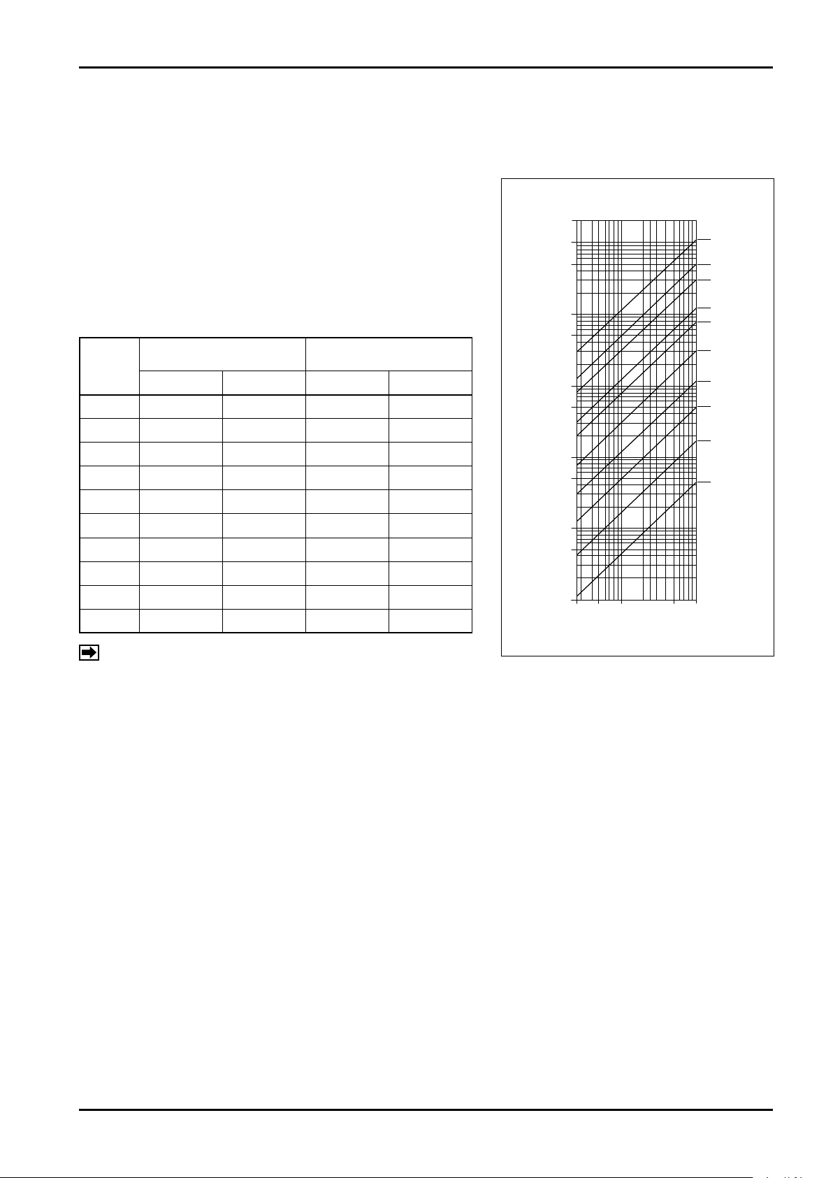
23. FLOW RANGE
20000
150
100
80
50
40
25
15
10
6
3
10000
5000
1000
500
100
50
10
5
1
0.5
0.1
0.25 0.5 1 2.5 5 10
Flow velocity (m/s)
Nominal size (mm)
Flow rate (L/min)
C−102-1-E
● Flow range and nominal size selection
Flow range can be selected between 0 to 0.5m/s and 0 to
10m/s, common to all nominal sizes. Determine the nominal
size that best suits your application using the flow velocity,
flow rate, and nominal size selector nomograph.
We suggest flow velocity of 2.5m/s or less for flows with
ab r asi v e slu r rie s an d 2.5m/ s or more f o r fl ows wi th
suspended solids.
●Flow range
Nominal
Size
(mm)
(Max. flow velocity 0.5m/s)
Min. range
L/min m3/h L/min m3/h
3 0 to 0.22 0 to 0.013 0 to 4.24 0 to 0.25
6 0 to 0.85 0 to 0.5 0 to 17 0 to 1
10 0 to 2.4 0 to 0.14 0 to 47 0 to 2.8
15 0 to 5.3 0 to 0.32 0 to 106 0 to 6.3
25 0 to 15 0 to 0.9 0 to 295 0 to 17.7
40 0 to 38 0 to 2.3 0 to 754 0 to 45.2
Max. range
(Max. flow velocity 10m/s)
●
Flow velocity, flow rate, nominal size
selector nomograph
50 0 to 59 0 to 3.5 0 to 1178 0 to 70.6
80 0 to 150 0 to 9 0 to 3015 0 to 181
100 0 to 236 0 to 14 0 to 4710 0 to 283
150 0 to 533 0 to 32 0 to 10667 0 to 640
NOTE: Be aware that accuracy varies with nominal size and
full-scale flow velocity.
51
Page 52
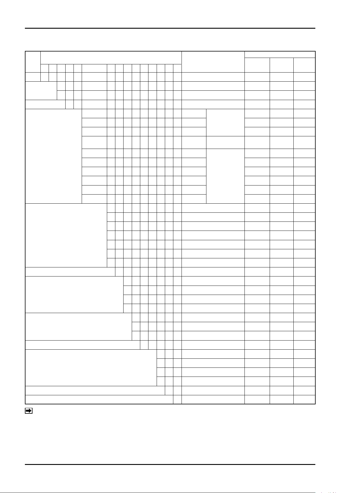
C−102-1-E
24. PRODUCT CODE EXPLANATION
Item
(1) (2) (3) (4)−(5) (6) (7) (8) (9)
Model
M G MAG-OVAL III ○ ○ ○
Body style
Configuration 1 − Integral with transmitter ○ ○ ○
Nominal size
Process connection
(pressure rating)
Lining material T Fluorocarbon polymers ○ ○ ○
Electrode material
Power source
Transmitter type E − Always "E" (PA28) ○ ○ ○
Earth ground electrode material
(identical with electrodes material)
Additional specifications (*2) 1 RS-485 communication ○ ○ ○
Version A ○ ○ ○
S Screw-in type ○ × ×
W Wafer type × ○ ○
Product Code
(10) (11) (12)−(13) (14) (15)
0 0 3 3mm
0 0 6 6mm ○ × ×
0 1 0 10mm ○ × ×
0 1 5 15mm
0 2 5 25mm
0 4 0 40mm × ○ ×
0 5 0 50mm × ○ ×
0 8 0 80mm × ○ ×
1 0 0 100mm × ○ ×
1 5 0 150mm × × ○
0 Always "0" for MGS type ○ × ×
1 JIS 10K × ○ ○
2 JIS 20K × ○ ○
3 JIS 30K × ○ ○
4 ASME 150, JPI 150 × ○ ○
5 ASME 300, JPI 300 × ○ ○
9 Other than above ○ ○ ○
1 SUS316L ○ ○ ○
2
5 Tantalum ○ ○ ○
7 Platinum ○ ○ ○
6 20 to 30VDC ○ ○ ○
7 85 to 264VAC 50Hz ○ ○ ○
8 85 to 264VAC 60Hz ○ ○ ○
1 SUS316L ○ ○ ○ (*1)
2
5 Tantalum ○ ○ ×
7 Platinum ○ ○ ×
Description
Screw
connection G1
Screw conn.
G1・1/4
Wafer type
Alloy C276 (HAST-C equiv.)
Alloy C276 (HAST-C equiv.)
Combination
Screw-in
3 to 15 A
○ × ×
○ × ×
× ○ ×
○ ○ ○
○ ○ ×
Wafer
25 to 100A
Wafer
150A
NOTES: *1: For nominal size 150mm, earth ring (SUS316) is attached between the joint face and the flange
instead of earth electrode.
*2: Special product is also available with Bell 202 communication. If you prefer, contact OVAL.
52
Page 53
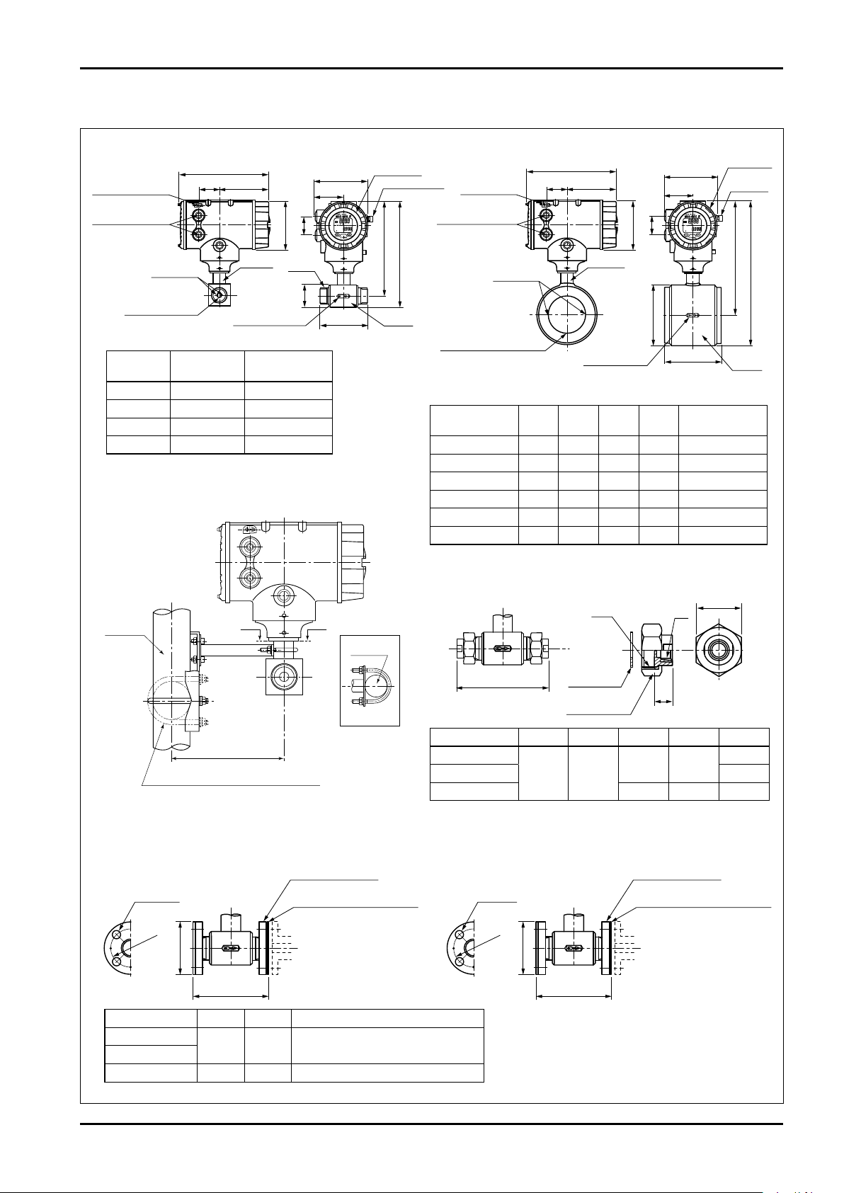
2″pipe
Adapter
Sec. A-A
181.6
A A
When installed on a horizontal pipe
C−102-1-E
145
79
130
50
253
283
60
240
Adapter
13356
Transmitter
Selector magnet
Transmitter
Selector
magnet
50
A
B
240
145
L
79
Adapter
Electrodes
13356
Cable entries G 1/2
Electrodes
GND electrodes
(2 places)
φ
131
φ
131
φ
D
G male
Screw
Flow dir. arrow
Std.: Left → right
Probe
●Nom. sizes 25 to 150mm (water type)
GND terminal
(M5)
GND terminal (M5)
Cable entries G 1/2
Flow dir. arrow
Std.: Left → right
Probe
Nom. Size 150mm is provided
with grounding rings
(without GND electrodes)
● Nom. sizes 3 to 15mm (screw type)
GND electrodes
4-φ15
Screw-in flange
Protector (wetted parts)
With fluorocarbon
polymers coating
143
φD2
φ
D1
● Screw-in flange for nom. sizes 3 to 15mm piping (option)
4-φ15
Screw-in flange
Protector (wetted parts)
141
φD2
φ
D1
Wetted parts: SUS316 Wetted parts: Coated with fluorocarbon polymers
S
G'
R
L1
Gasket
Fitting nut
L2
Dimension with
fittings installed
●
Pipe union for nom. sizes 3 to 15mm piping (std. accessory)
Wetted parts: SUS316 (std.)
25. OUTLINE DIMENSIONS
Nom. size
mm
● Nominal sizes 3 to 6mm Transmitter
hold-down hardware
Screw conn.GApprox. Weight
3 G1 5.7
6 G1 5.7
10 G1 5.7
15
G1・1/4
kg
5.8
All dimensions in millimeters
Nom. size mm L A B φD
25 100 293 258 70 5.8
40 100 309 266 80 6.5
50 100 323 273 100 7.1
80 150 353 288 130 9.8
100 150 374 303.5 161 12.4
150 210 441 332 218 21.9
Approx. Weight
kg
Nom. size mm L1 L2 S G' R
3, 6
10 Rc 3/8
15 50
Nom. size mm D1 L2 Remarks
3, 6
10
15 70 95 Nom. Size 15 mm JIS 10K equivalent
65 90 Nom. Size 10mm JIS 10K equivalent
172 20
41 G1
G1・1/4
Rc 1/8
Rc 1/2
53
Page 54

C−102-1-E
All specifications are subject to change without notice for improvement.
2016.06 Revised
2014.04 Released
C-102-1-E (2)
 Loading...