

Page 1
Ins. No.
B-320-2-E
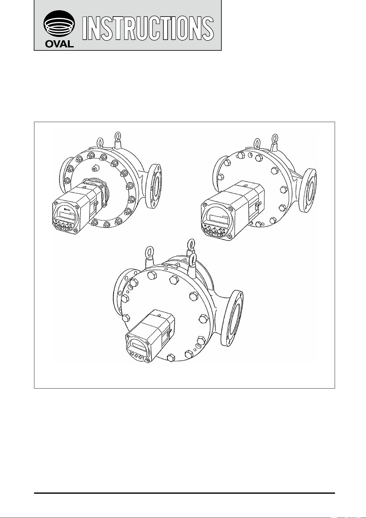
Batch controller equipped ULTRA OVAL
Meter Sizes: 28, 29, 31 and 60
Register Model: LW76E
Sizes 28, 29, 31, and 60
Double Case Construction
(two-step open/two-step shutoff)
Size 29
Single Case Construction
Sizes 60 and 31
Single Case Construction
Every OVAL owmeter is fabricated, inspected, and tested under stringent quality control prior to shipment
from the factory. In order to maintain its design performance throughout its life, this manual offers the operator
the necessary instruction, operation and maintenance information. Be well familiar with these instructions
before you place the meter in service and keep this manual at the eld location for ready reference.
About Meter Size Designation
◆
The size of OVAL positive-displacement owmeters is basically identied by a two-digit
code.
◆
1
Page 2

B-320-2-E
CONTENTS
1. BEFORE YOU BEGIN ........................................................................................................................4
1.1 Conrming the Nameplate .............................................................................................................4
1.2 Transportation Considerations ....................................................................................................... 4
1.3 Storage Considerations .................................................................................................................4
1.4 Operating Precautions ................................................................................................................... 5
2. OPERATING CONDITIONS ................................................................................................................6
3. GENERAL ...........................................................................................................................................6
3.1 General Description .......................................................................................................................6
3.2 Features and Functions ..................................................................................................................7
3.3 Part Name ......................................................................................................................................8
3.4 About Safety Features ....................................................................................................................9
4. FLOWMETER INSTALLATION .........................................................................................................11
4.1 Considerations at Installation ....................................................................................................... 11
4.2 Standard Installation, Horizontal Line ..........................................................................................12
4.3 Standard Installation, Vertical Line ........................................................................................................... 12
4.4 Example of Incorrect Installation .................................................................................................. 12
4.5 How to Change Display Orientations (changing ow directions) .................................................12
5. AIR SIGNAL LINE CONNECTIONS .................................................................................................13
5.1 System Conguration with LW76E Register Equipped Meter
(1-step open/2-step close or 2-step open/2-step close) ............................................................. 13
5.2 Air Signal Line Connections ......................................................................................................... 13
5.3 Operation Time Chart and Pneumatic Circuit .............................................................................. 14
6. ABOUT DISPLAY AND PUSHBUTTONS ........................................................................................16
6.1 Display Functions .........................................................................................................................16
6.2 Pushbutton Inspection and Cleaning ...........................................................................................17
6.3 Pushbutton Functions ................................................................................................................. 18
6.4 Switch Functions .......................................................................................................................... 19
6.4.1 Selecting Add and Subtract Counter ..................................................................................... 19
6.4.2 Selecting Setup and RUN Mode ............................................................................................19
7. RECONFIGURATION .......................................................................................................................20
7.1 Establishing a Batch Setpoint ...................................................................................................... 20
7.1.1 Procedure (batch setup mode) ..............................................................................................20
7.1.2 Example of Establishing a Batch Setpoint .............................................................................21
7.2 Parameter Setup (cumulative total, scaler factor, frequency division, initial and nal
settings, missing pulse detection, overshoot setting) ..................................................................22
7.2.1 Operation in the Setup Mode ................................................................................................. 23
8. OPERATION .....................................................................................................................................24
8.1 Preparation Before Operation ...................................................................................................... 24
8.2 Preoperational Checks ................................................................................................................24
8.3 Operation with Actual Flow .......................................................................................................... 25
8.4 Operating Precautions ................................................................................................................ 25
8.5 Precautions at Operation Shutdown ............................................................................................26
8.6 Strainer Inspection ....................................................................................................................... 26
8.7 Starting a Batch Process ............................................................................................................. 27
8.7.1 Preoperational Checks Before a Batch Process .................................................................... 27
8.7.2 Starting a Batch (procedure) ................................................................................................. 27
9. INSPECTION ....................................................................................................................................29
9.1 Register Inspection ...................................................................................................................... 29
9.2 Register Disassembly .................................................................................................................. 30
2
Page 3

B-320-2-E
9.3 Meter Body Disassembly and Inspection ....................................................................................32
9.3.1 Single-case Construction Meter Body Disassembly and Inspection ..................................... 32
9.3.2 Single-case Construction Meter Body Assembly Procedure .................................................33
9.3.3 Double-case Construction Meter Body Disassembly and Inspection ...................................34
9.3.4 Double-case Construction Meter Body Assembly Procedure ............................................... 35
10. ABOUT THE BATTERY PACK .......................................................................................................36
10.1 Battery Life ................................................................................................................................. 36
10.2 Battery Pack Replacement ........................................................................................................36
11. TROUBLESHOOTING ....................................................................................................................37
12. EXPLODED VIEWS AND PARTS LIST .......................................................................................... 40
12.1 Size 29 Single Case Construction Meter Exploded View and Parts List ...................................40
12.1.1 Size 29 Single Case Construction Meter Exploded View ....................................................40
12.1.2 Size 29 Single Case Construction Meter Parts List .............................................................41
12.2 Size 60 Single Construction Meter Exploded View and Parts List.............................................42
12.2.1 Size 60 Single Construction Meter Exploded View .............................................................. 42
12.2.2 Size 60 Single Case Construction Meter Parts List .............................................................43
12.3 Size 31 Single Case Construction Meter Exploded View and Parts List ...................................44
12.3.1 Size 31 Single Case Construction Meter Exploded View ....................................................44
12.3.2 Size 31 Single Case Construction Meter Parts List .............................................................45
12.4
Sizes 28, 29, and 31 Double Case Construction Meter, 10K type Exploded View and Parts List .............. 46
12.4.1 Sizes 28, 29, and 31 Double Case Construction Meter, 10K type Exploded View ..............46
12.4.2 Sizes 28, 29, and 31 Double Case Construction Meter, 10K Type Parts List ...................... 47
12.5 Size 60 Double Case Construction Meter, 10K type Exploded View and Parts List .................. 48
12.5.1 Size 60 Double Case Construction Meter, 10K type Exploded View ...................................48
12.5.2 Size 60 Double Case Construction Meter, 10K Type Parts List ........................................... 49
12.6
Sizes 28, 29, and 31 Double Case Construction Meter, 30K type (F3) Exploded View and Parts List ................ 50
12.6.1 Sizes 28, 29, and 31 Double Case Construction Meter, 30K type (F3) Exploded View ....... 50
12.6.2 Sizes 28, 29, and 31 Double Case Construction Meter, 30K Type (F3) Parts List ...............51
12.7 Size 60 Double Case Construction Meter, 30K type (F3) Exploded View and Parts List ................ 52
12.7.1 Size 60 Double Case Construction Meter, 30K type (F3) Exploded View ............................52
12.7.2 Size 60 Double Case Construction Meter, 30K Type (F3) Parts List .................................... 53
12.8 Register Exploded View and Parts List ...................................................................................... 54
13. GENERAL SPECIFICATIONS ........................................................................................................55
"NOTE", "CAUTION" and "WARNING" in this manual are to promote awareness of users and each
word has meaning as follows.
NOTE: Notes are separated from the general text to bring the user's attention to
important information.
CAUTION: Caution statements signal the user about hazards or unsafe practices
which could result in minor personal injury or product or property damage.
WARNING: Warning statements signal the user about hazards or unsafe practices
which could result in severe personal injury or death.
3
Page 4
B-320-2-E
NAMEPLATE
(RATINGS)
ULTRA OVAL
MADE IN JAPAN MNPJ-237
OVAL Corporation
MODEL
MAX PRESS.
FLOW RANGE
CONT.
~
~
FULL SCALE
TEMP.
PULSE UNIT
SERIAL No.
FLUID
DATE
SIZE
METER FACTOR
TAG. No
INT.
NOTES
1. When measuring other liquids, consult us.
2. Place the meter body (outer case) in a horizontal
position. For details, see instruction manual.
1. BEFORE YOU BEGIN
Every ULTRA OVAL with a batch control feature is thoroughly tested before it leaves the factory. When
received, it should be thoroughly inspected for indication of rough handling during transit. Necessary handling
precautions are described in this section; read the instructions carefully. As for other information, find the
respective sections from "CONTENTS" on pages 2 and 3.
For any inquiries, contact your nearest OVAL sales ofce.
CAUTION: When you make inquiries, include the product name, model number,
product number, ratings and other pertinent information.
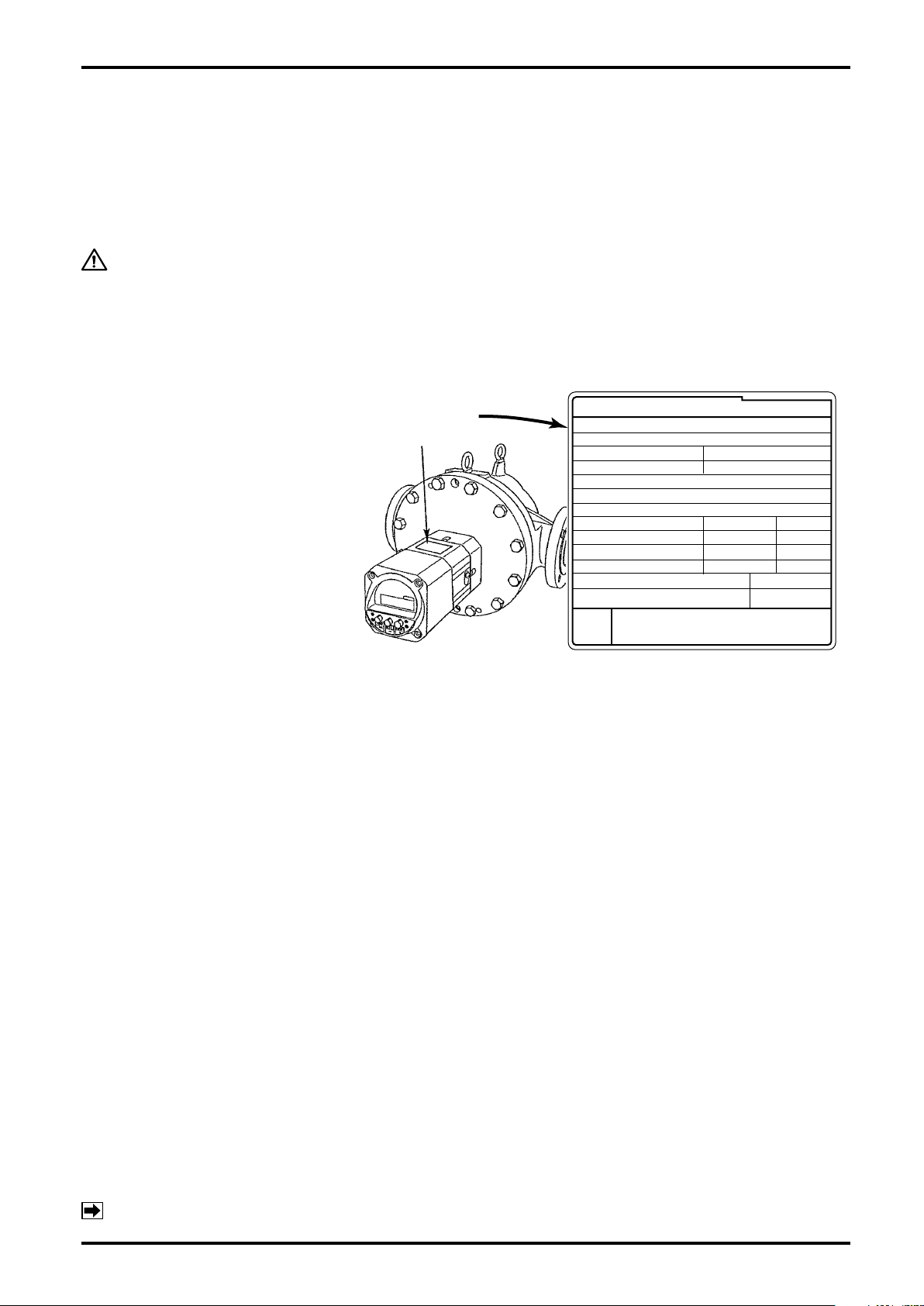
1.1 Conrming the Nameplate
Every Ultra OVAL is assembled and
adj uste d acc ord ing to i n divi dual
specications.
Product co de number and ratings
are stated on the register nameplate.
Make sure that, the ratings shown
conform to your particular specication.
1.2 Transportation Considerations
(1) To safeguard against damage during transit, transport the Ultra OVAL to the installation site in the same
(2) Ultra OVAL is adjusted and inspected as an assembly consisting of the meter body, sensor and register. It
(3) The register is accurately congured and adjusted. Do not remove its front cover to gain access to its
1.3 Storage Considerations
If your Ultra OVAL is stored for long periods of time upon receipt before installation, unexpected faulty
conditions could result. If a long-term storage is anticipated, take the following precautions:
(1) Keep the Ultra OVAL in store in the same shipping container used for transportation from OVAL if possible.
(2) Place of storage should conform to the following requirements:
(3) Purge the Ultra OVAL that has once been placed in service with clean air, N2 gas, etc. to prevent the
(4) In case of storage for extended periods of time, good practice is to remove the battery pack from the
4
container used for transportation from the factory if circumstances permit.
should therefore be handled as an integral assembly.
internal assembly except for reconguration.
- Free from rain and water.
- Free from vibration and impact shocks.
- Temperature and relative humidity in the storage place are at or near room temperature and humidity
(around 25°C and 65%).
metered uid from adhering to the meter connections, piping inner walls, housing, etc. before storage. (Wash
clean with suitable detergent if necessary.)
register.
NOTE: See Sec. 10.2 "Battery Pack Replacement" on page 36.
Page 5

B-320-2-E
Wrap This Way
Leave
Two Threads
Unwrapped
Seal Tape
1.4 Operating Precautions
(1) Operating precautions to be observed
1) Do not attempt to change component parts or modify circuits of the register.
2) Do not paint out the warning label or remove warning and specication labels printed or attached to the
register. Applying a coat of paint to synthetic resin components, such as pushbuttons, may possibly
result in malfunction of the affected components by the solvent it contains.
3) Since the solenoid valve to control the operation signal of the shutoff valve installed in the owmeter
register is of an internal pilot type, proper switching of the signal may be hindered if the supply air
pressure connected to "IN" port of the solenoid valve unit falls below 0.20MPa.
For this reason, do not use it for controlling an emergency shutoff valve or similar equipment.
4) To prevent accident possibly caused by the failure of the owmeter counter or continuous ow valve
of this owmeter, be sure to install a safety valve such as manual valve in the OUT side piping of the
continuous ow valve. The safety valve must be closed when the owmeter is not in operation.
(2) About the quality of air source (uid for actuating the shutoff valve [air, nitrogen, etc.])
(See JIS B 8370 "Guidelines to Pneumatic Systems.")
1) Avoid using compressed air that contains synthetic oil with chemicals or other organic solvent, sodium,
corrosive gas, etc. which may cause component parts failure or malfunctioning.
2) Use clean, dry air that does not condensate at operating temperatures in the environment where the
product is placed in service.
Provide an air lter at the air source (ltration accuracy 5 μm approx. or ner).
3) Supply pressure to the owmeter register is 0.20 to 0.69MPa. Adjust the pressure to somewhere in this
range with reducing valve or similar regulator.
4) A solenoid valve to control the operation signal of the shutoff valve is incorporated in the flowmeter
register.
Large quantities of drain may cause malfunctioning of the solenoid valve and other pneumatic equipment
used besides environmental pollution. Careful considerations must therefore be made in handling of drain.
In case such handling is difcult, good practice is to provide an auto drain equipped lter.
5) Powder carbon produced from the compressor can build up on valve interior in quantities leading to
valve malfunction. To get around this problem, select a compressor oil that produces less powder
carbon and/or provide an oil mist separator.
(3) About the operating environment
In low temperature applications, due precautions should be taken against solidied or frozen drain or water
inside the solenoid valve. In a case like this, we recommend to provide a dehumidier, such as a dryer, to
remove uid to be drained and water content.
NOTE: The above mentioned compressed air purication equipment are available from OVAL as an option.
(4) About piping
1) Preparation for installation
Prior to installation, thoroughly remove construction debris, such as metal chips, cutting uid, and other
foreign matter remaining in the piping system by air blow (ushing) or cleaning.
2) Wrapping the seal tape
When screwing in pipes and fittings, exercise care to preclude metal
chips produced in pipe screw-thread cutting and fragments of seal tape
from entering the valve. If thread seal tape is used, leave 1.5 to 2 threads
to remain unwrapped.
3) Before making pipe connections
Refer to the instruction manual to ensure that pipes are connected to the
right ports.
4) For air supply to actuate shutoff valve, use φ6 × φ4 copper tubes.
(5) About maintenance and inspection
(Refer to JIS B 8375 "4- and 5-port Pneumatic Solenoid Valves".)
In order to ensure normal operation of the register, do not fail to test it by pressing the start/stop button of
the register alternately several times without owing the process uid. This test will indicate whether the
solenoid valve in the register works properly or not.
5
Page 6

B-320-2-E
2. OPERATING CONDITIONS
To maintain the stated high accuracy and long service life of the Ultra OVAL, make sure that owrate, pressure,
temperature and viscosity are within the ratings as stamped on the meter register tag (page 4).
CAUTION
(1) Although allowable ambient temperature is up to +60°C for explosionproof units, it is
desirable that the meter be used at room temperature and humidity.
(2) In cases where the register is exposed to elevated temperatures due to exposure to
direct rays of the sun or to radiant heat, ensure, by providing a sunshade or similar
protection, that the meter is used within the operating temperature range (-10 to +60°C).
(3) Avoid such installation locations as:
1) hardly accessible for maintenance and inspection.
2) temperature variation and/or vibration is excessive.
3) potential danger of immersion in water.
4) corrosive gases exist.
5) not compatible with the explosionproof construction of this meter.
6) large electromagnetic noises are highly expected.
3. GENERAL
3.1 General Description
The Ultra OVAL is a high-precision owmeter combined with a user friendly batch controller for use in the eld.
Its electronic register is programmable with front pushbuttons for batch processes (or quantities of the process
uid to be delivered). When used in combination with a pneumatic shutoff valve, you can build an automatic
metering system which opens the shutoff valve upon depression of the start button and shuts it off when a
preset quantity of the process uid is reached.
The register combined with this meter is the LW76E which features a two-step open, two-step close (or onestep open, two-step close) arrangement. Applications include batch processes in chemical plants, blending,
lling, or clearance processes in the food, pharmaceutical, paint, petroleum, and chemical products industries
to save time and effort, streamline processes, and achieve product uniformity.
In this meter, an amorphous sensor detects the fluid flow by picking up the magnetic fields of permanent
magnets embedded in the oval rotors of proprietary contoured gear profile. As a result, high reliability of
achieved.
6
Page 7

B-320-2-E
START
▲
3.2 Features and Functions
(1) Long life
Absence of mechanically sliding components except for oval rotors, solenoid valve and control buttons
contributes to long service life. Small wetted parts count and pocketless design makes this meter ideally
suited for ow measurement of chemical liquids.
(2) Electronic register saves time and effort in metering operations.
1) Figures in the LCD display are 12.7mm high for easy readability.
2) Batch setpoint (6-digit) and cumulative total count (8-digit) are selectable with a switch for management
of totals.
3) Front pushbuttons select the desired batch setpoint.
4) Add or subtract counter in the batch process is selectable (subtract counter is standard).
5) Advance signal can be set at any point in a range from 0 to 999 counts.
6) The duration of missing ow signal pulses can be set at any point from 0 to 15 seconds.
7) An overshoot (overmeasurement) can be set at any point from 0 to 99 counts.
8) Can resume a metering cycle for the remainder of a batch that has been interrupted by an emergency
stop.
9) Can review the batch setpoint upon depression of
button while a batch cycle is in progress.
(3) Installation location
The register is of waterproof construction (JIS C 0920 Weathertight) for installation outdoors. Its intrinsically
safe explosionproof construction (Exia II BT3) permits installation in hazardous locations (Divisions 0, 1, and
2 area) (explosionproof models only).
(4) Field work required
1) Battery powered, it eliminates the need for an external power source (eld wiring not required). The
built-in battery is good for four years (battery life may vary according to the operating conditions). (A
low battery alarm "BATT" ickers in the front LCD when the battery is near to its end.)
2) Replacing the existing OVAL register (LW76) with this new model does not require another air source;
the existing shutoff valve remains serviceable.
(5) Affords adequate protection in batch processes
1) In the model equipped with LW76E register, the shutoff valve opens and closes moderately by the initial
and final flowrate control signals: the arrangement eliminates static electricity buildup in the piping
assembly and in the tank at startup, and prevents hydraulic shock at valve closure.
2) If something erratic (missing owrate signal, for example) occurs in the batch process, a shutoff valve
closure signal is automatically generated.
3) The operator can monitor shutoff valve operation signals, alarmed conditions, and other status with
front LCD illumination in its 1st and 8th digit segment.
4) In the event the battery has run down during the batch process, safety is maintained by shutting off the
valve automatically. Parameters and variables are retained in the E2PROM (nonvolatile memory): you will
not be required of setting them up all over again after battery pack replacement.
(6) Simplied maintenance
The electronics is of modular and printed circuit board construction, housed in a plastic casing; pneumatic
circuitry (solenoid valve assembly), control buttons, and battery pack are of independent units for maximum
ease of maintenance.
NOTE:
⇨
With the use over an extended period of time, meter error will deviate more or less
from that in initial factory calibration. Upon request, we may conduct an instrumental
error testing once again and establish a "new meter factor" in the scaler when your
Ultra OVAL is returned to the factory for periodic inspection or for other reason.
7
Page 8
B-320-2-E
Explosionproof Certification
Plate
Exhaust
View "A"
LCD Display
(Total counter and
operation status)
Unit of Total Plate
Front Cover Fitting
Hex Soc. Hd. Bolt
OUT1
OUT2
IN
A
Air Signal
Connections
Cooling Tube
(or Heating Tube)
Flow Direction Arrow
Meter Body
Flowmeter
Rear Cover
Register Front Cover
Register Body
(Battery pack built in)
Connecting Flange
EXT. GND Terminal
Label (Ratings shown)
STOP Button
(ROT. Button)
RESET Button
(
Button)
▲
START Button
(▲Button)
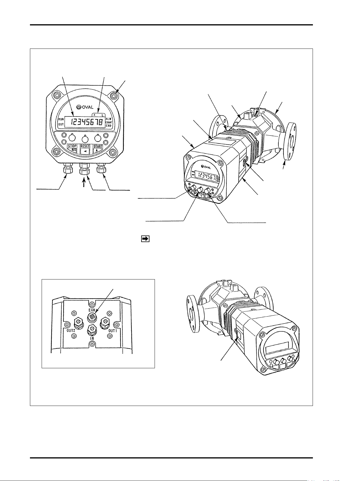
3.3 Part Name
Nameplate (Ratings shown)
NOTE: Shown here is the appearance of the register
combined with Size 29 single-case meter.
Fig. 3.1
8
Page 9

B-320-2-E
START
▲
3.4 About Safety Features
The register is provided with the following safeguards:
(1) On detection of missing pulses
Either condition 1) or 2) causes the indicator "ALM" in the display to light and the shutoff valve to close
automatically for safety’s sake.
1) The register fails to count any pulses within preset missing pulse period (PL) from the moment a batch
process started.
2) Counting pulses is interrupted during a batch process and remains interrupted beyond preset missing
pulse period (PL).
The electronics starts missing pulse detection 5 seconds from the start of a batch process; actually a
missing pulse setpoint (PL) + 5 seconds is required for this function to go into effect.
Large totalizer units of measure (weights of the total count) by frequency reduction or other processing may
require more time to update the count, but such a condition will not trigger a missing pulse detection alarm.
If "0" is chosen for missing pulse setpoint (PL), the capability to detect missing pulses will remain disabled.
For manual batch processing, therefore, we recommend you to use a setpoint at "0."
(2) On detection of an overshoot (overmeasurement)
An overshoot of measurement at the end of a batch does occur due to some time lag in shutoff valve
actuation (on closure). An indicator "ALM" in the display lights when the register counts more than the
anticipated overshoot count (oV).
NOTE: While "0" is chosen for anticipated overshoot count (oV), the overshoot detection feature remains
disabled.
(3) On detection of a low battery
A weak built-in battery tells the operator with a blinking alarm "BATT" in the display. When the battery
has run down nearly to its end, the "ALM" comes on, the shutoff valve closes automatically (if in an open
position) and, at the same time, the variables (total count in a batch process and cumulative total count) are
evacuated to a nonvolatile memory.
From this moment onward, valve operation will remain inoperative (
button will not respond). As a
rule of thumb, it takes about 8 days from a blinking "BATT" alarm till a stay-on "ALM." It is suggested that
the old battery be replaced with a new one during this period.
NOTE: A low battery when left unused for some time may restore its energy to some extent and may be
used for a batch job again, only for an unpredictable length of time. Do not fail to replace a battery
that has once caused the "ALM" to come on.
9
Page 10
B-320-2-E
STOP
ROT.
STOP
ROT.
RESET
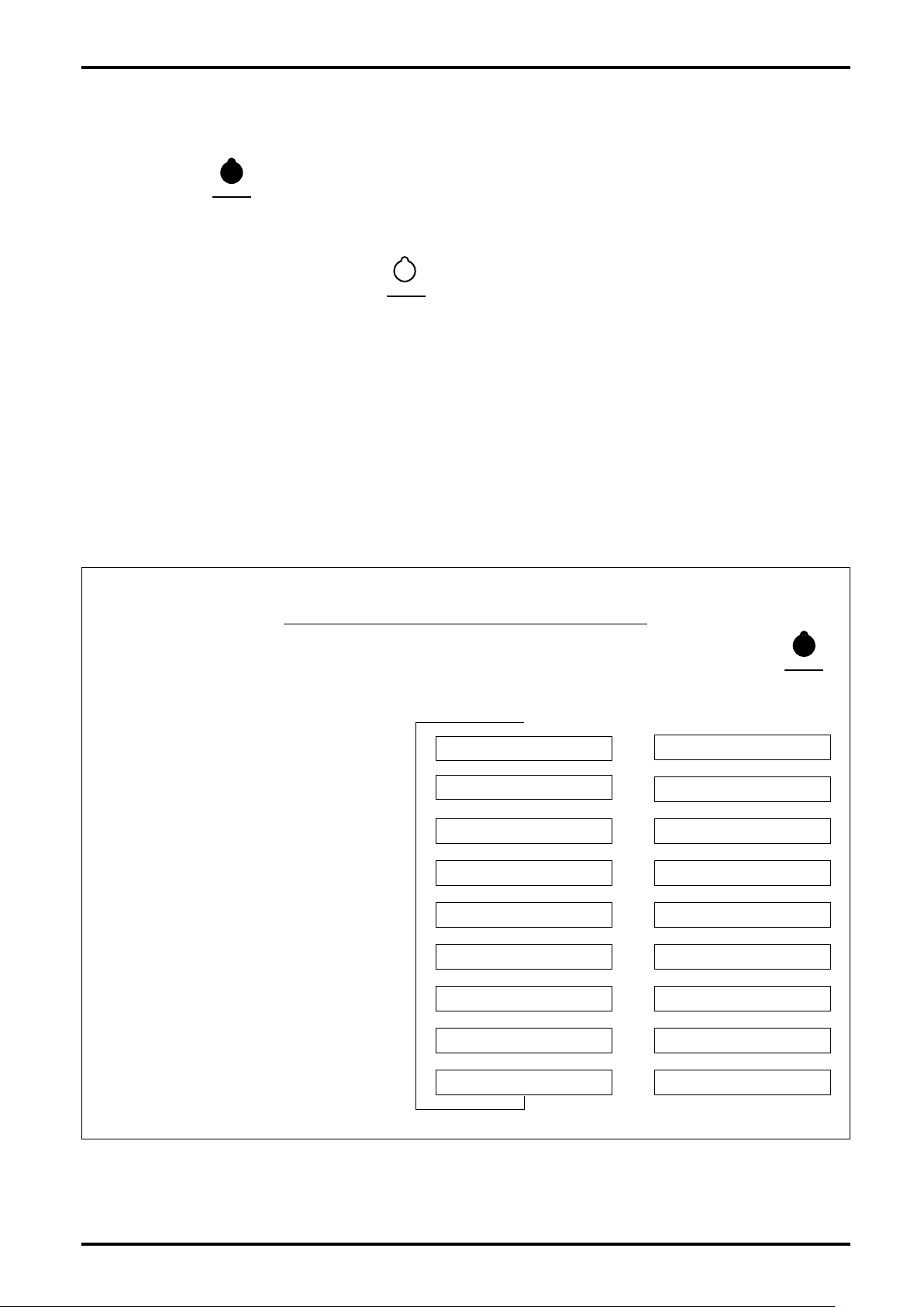
(4) Upon detection of a parameter error
in response to any error in parameter setting, an alarm message "DATA Err" appears in the display.
1) Each time
button is depressed in this case, the display scrolls through available data so that the
operator can conrm which parameter is in trouble (see Figure below).
2) Following acknowledgement, press
.
(A message "DATA Err" will then disappear and all data will be reset.)
3) Following the resetting, set parameters and batch setpoint again according to the specications.
(Follow the procedure described in Section 7 "RECONFIGURATION".)
Messages on Detection of Parameter Errors
(Parameters)
Batch setpoint (preceded by "b") ..............
◦
Accumulated total to batch setpoint .........
◦
Accumulated total ......................................
◦
Scaler factor ..............................................
◦
Frequency reduction ..................................
◦
Initial setting ..............................................
◦
Final setting ...............................................
◦
Missing pulse setpoint ...............................
◦
Overshoot setpoint ....................................
◦
↓
b □ □ □ □ □ □ □
↓
□ □ □ □ □ □ □ □
↓
□ □ □ □ □ □ □ □
↓
F □ □ □.□ □ □ □
↓
d □ □ □ □ □ □ □
↓
o P □ □ □ □ □ −
↓
c L □ □ □ □ □ −
↓
P L □ □ □ □ □ □
↓
o V □ □ □ □ □ −
: Press
↓
: Shows alternately.
⇔
⇔
D A T A E r r
⇔
D A T A E r r
⇔
D A T A E r r
⇔
D A T A E r r
⇔
D A T A E r r
⇔
D A T A E r r
⇔
D A T A E r r
⇔
D A T A E r r
⇔
D A T A E r r
.
10
Page 11
B-320-2-E
(LEVEL)
ULTRA OVAL REGISTER
WITH BATCH CONTROLLER
BYPASS LINE
STRAINER
VALVE
FLOW DIRECTION
SHORT PIPE
SHUTOFF
VALVE
4. FLOWMETER INSTALLATION
4.1 Considerations at Installation
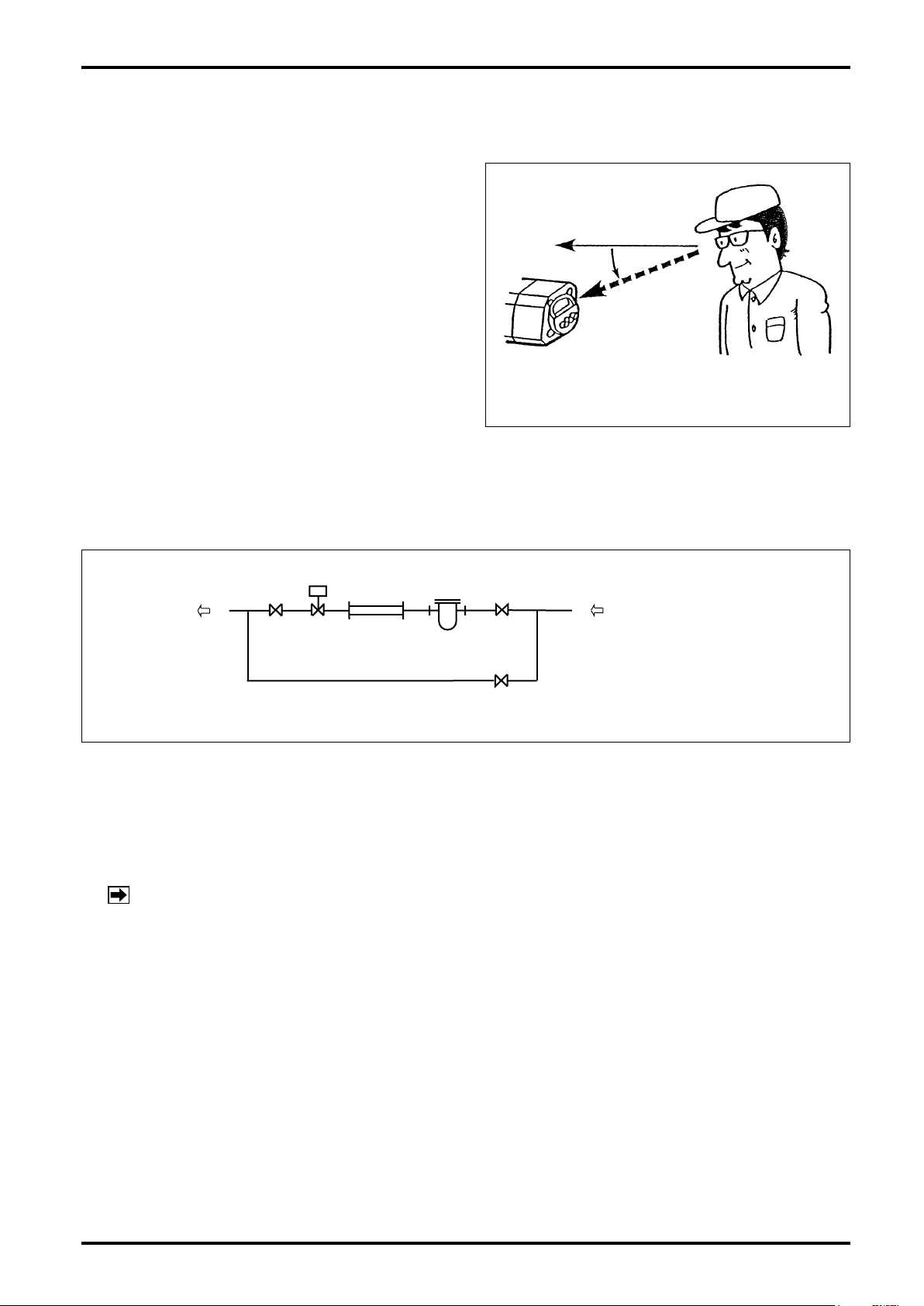
(1) The LCD display of Ultra OVAL equipped with
a batch controller is designed to be seen down
from upper point, rather than at the same level.
Take this into consideration when you decide its
installation height.
Fig. 4.1
(2) Flush the piping assembly.
Flushing must be performed before meter installation. Install a short pipe in place of the meter at this time (see
Fig. 4.2 below).
(3) After ushing, remove the short pipe section from the pipeline and install the meter in place, exercising care
to avoid any pipe strain on the meter.
(4) The meter must be installed on the discharge side of the pump.
(5) If the meter is to be used under tank head, give a head pressure greater than the total pressure losses of
the piping system, strainer, meter, and other associated equipment.
NOTE: Pressure losses of the Ultra OVAL with a batch controller and strainers are stated in the
GENERAL SPECIFICATIONS.
(6) The ow direction arrow indicated on the meter body should point in actual direction of ow.
(7) The strainer should be located upstream of, and in close proximity of the meter.
(8) Since the sensor in the Ultra OVAL detects the changes in magnetic ux density, it must be isolated from
the inuence of external magnetic elds.
In order to minimize the inuence of external magnetic elds, select an installation location at least 5 meters
from existing power equipment and conductors - potential sources of creating large magnetic and electric
elds, such as motors and generators.
(9) If electrical heating is considered, consult the factory.
(10) If heat retention is desired, do not allow lagging material to cover up the meter adapter and register
assembly.
Typical examples of Ultra UF-II installation are shown on the next page.
●
Fig. 4.2
11
Page 12
B-320-2-E
BYPASS
STRAINER
REGISTER
ADAPTER
*
(
1000mm
)
OU
T
REGISTER
CAREFULLY ROTATE
ADAPTER
OUT
IN
B
A
OU
T
!
WRONG
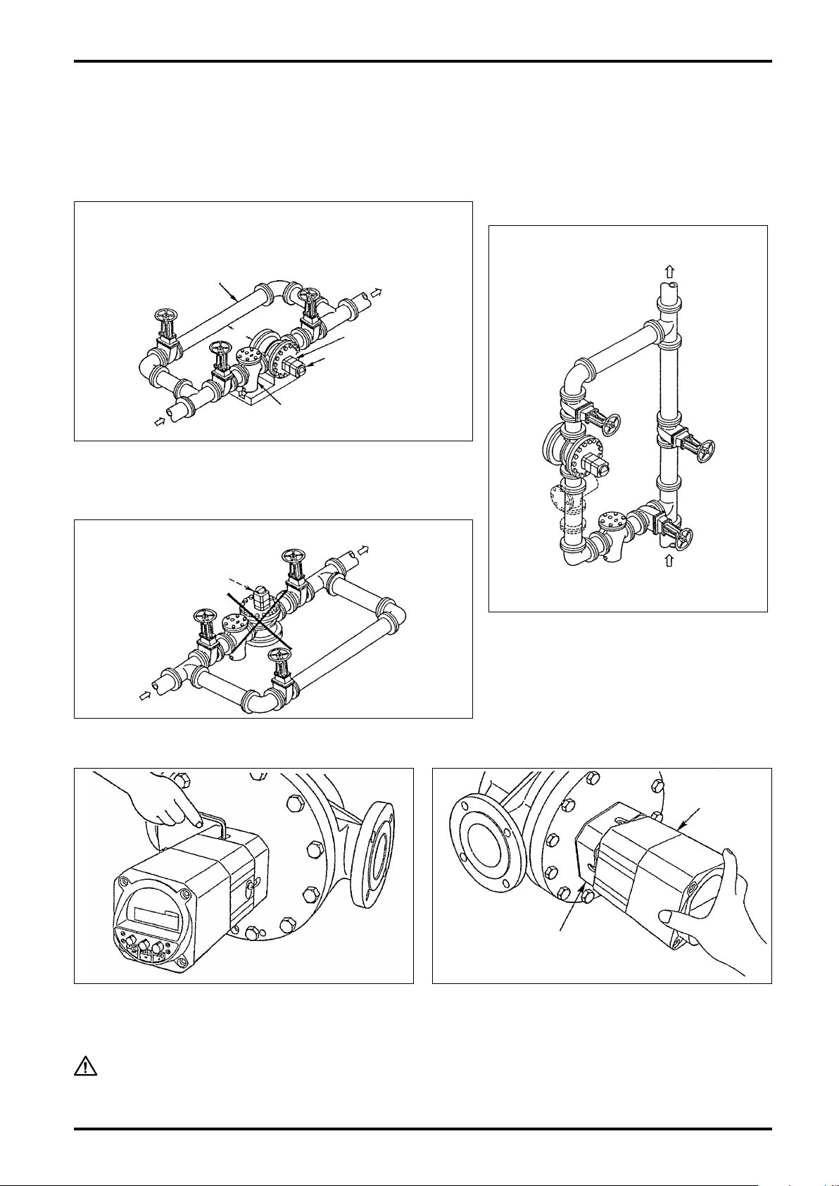
4.2 Standard Installation, Horizontal Line
(1) In case flow direction is from R to L, change places of
meter and strainer.
(2) Arrange piping so as to facilitate drainage.
(3) Strainer should be inspected on a regular basis.
Marked * is the space required
for disassembly and inspection.
4.4 Example of Incorrect Installation
(1) Do not install the meter in a position like this.
4.3 Standard Installation, Vertical Line
(1) If the ow direction is from top to bottom,
change places of meter and strainer.
(2) Installing the strainer at "B" will make
net reinstallation difcult at cleaning; we
recommend to install the strainer at "A".
4.5 How to Change Display Orientations (changing ow directions)
(1) Take off four hex socket head screws (M6) with
NOTE:
Fo r o utl i n e dim e n sion s a nd p i p e
c o nn e ct i on d i m s . , see a p p ro v al
drawing.
hex wrench.
CAUTION Never rotate the register assembly more than one complete revolution.
Do not attempt to separate the register assembly from the meter body
to change the flow directions.
(2) Holding the register in both hands, carefully
rotate it to a desired orientation of the new ow
direction, and secure it with hex socket head
screws.
12
Page 13
B-320-2-E
Flow Direction
IN
OUT 1
EXH
ULTRA OVAL with Batch Controller
(LW76E)
Filter/Reducing Valve
OUT 2
To Pump
(Contact-closure
signal)
SV
MV
FPD1
Air Press. to Valve *2
Signal Air Press.
0.20 to 0.69MPa
Air
Directional
Valve
Double Torque Cylinder
Ball Valve
※ 1
Note: *2 depends on the specification of the valve.
EXTERNAL
GND TERMINAL
EXH
(EXHAUST)
OUT 1 OPEN SIGNAL
IN AIR SUPPLY
OUT 2 CLOSE SIGNAL
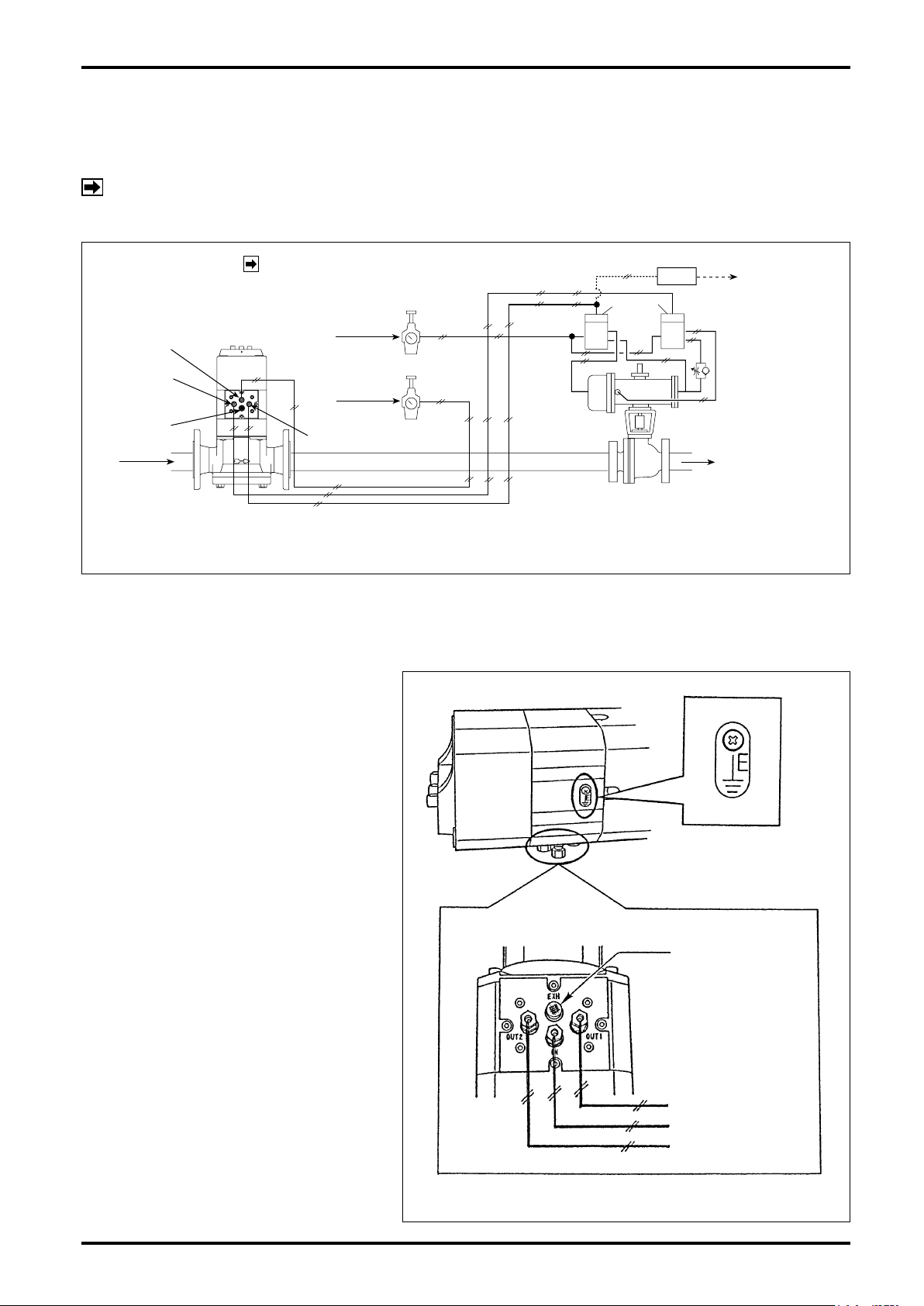
5. AIR SIGNAL LINE CONNECTIONS
5.1 System Conguration with LW76E Register Equipped Meter
(1-step open/2-step close or 2-step open/2-step close)
NOTE: For simplicity's sake, the Ultra OVAL (*) with a batch control feature is shown here in an upright
position. In practice, the owmeter should be installed in the physical orientation shown in Sections
4.2 and 4.3.
Fig. 5.1
NOTE: When combined with OVAL pneumatic-electrical switch (Model FPD1), the pump can be
interlocked.
For complete details, see the pneumatic-electrical switch instruction manual.
5.2 Air Signal Line Connections
The register contains a pneumatic circuits
to which air signal lines of copper tubing
are connected through their ports below the
register body.
- Air pressure: 0.20 to 0.69MPa
(adjusted to shutoff valve
specication.)
(Must be clean air)
- Air tubing diam.: Use φ6 × φ4 copper tubing.
(Bite-type couplings
(Rc1/8) are provided.)
- Output air connections
OUT 1: Main valve (MV) open signal
OUT 2: Small valve (SV) close signal
IMPORTANT: At the supply air
connection, be sure to
provide a reducing valve
furnished with a filter
(Model 1301-8002).
Fig. 5.2
13
Page 14
B-320-2-E
START
▲
INITIAL FLOW CONTROL
(INITIAL SETTING)
OUT 2
(SV)
OUT 1
(MV)
ON
OFF
ON
OFF
START SIGNAL
VALVE POSITION
(FLOWRATE)
INITIAL FLOWRATE
A
B
C
D
E
TIME
ANTICIPATED
OVERSHOOT
END OF A BATCH
FINAL FLOWATE
UPPER LIMIT FLOWRATE
STOP SIGNAL
FULL OPEN SIGNAL
ONE-STEP OPEN SIGNAL
TARGET BATCH SET VALUE
FINAL FLOW CONTROL
(FINAL SETTING)
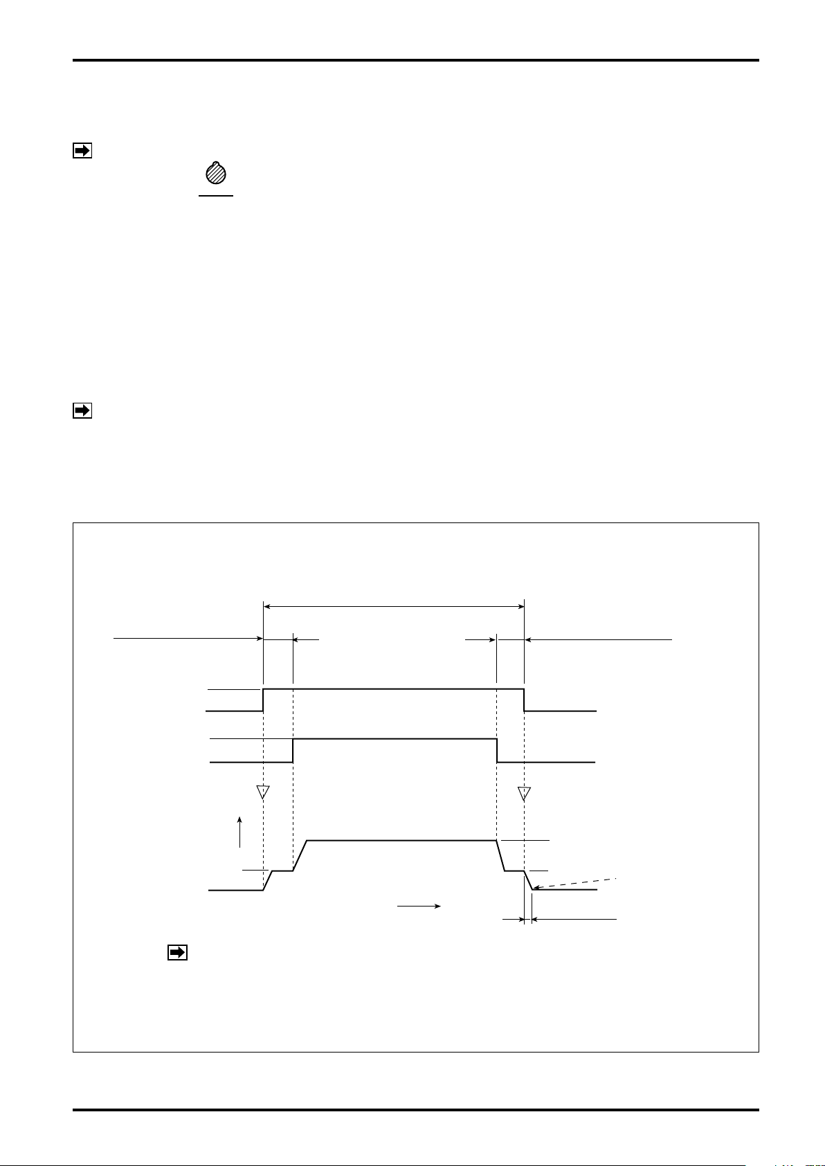
5.3 Operation Time Chart and Pneumatic Circuit
Description of Operation Time Chart
■
NOTE: Operation can best be understood by referring to the chart below.
Upon depression of
. button, the shutoff valve opens to a predetermined position (initial owrate). When a
predetermined quantity (from point A to point B) has been delivered, the valve opens fully; when metering has
reached point C, the valve automatically throttles the ow and maintains a predetermined valve position (nal
owrate).
At point D (batch setpoint), a closure signal (full closure signal) is generated.
However, due to a time lag in valve actuation, inherent to the type of valve used, the valve actually closes at
point E. Since the amount from point D to point E can be anticipated (an overshoot or over measurement),
we determine the right batch setpoint corrected for this overshoot. If an overshoot exceeds a predetermined
quantity, the register sets off an alarm.
Safe and precise measurement is thus achieved. In practice, we preselect valve positions A → B and C → D on
the part of the shutoff valve.
NOTE: In a model equipped with LW76E register, manual interruption while the valve is fully open causes
the shutoff valve to close in one step and, when operation is resumed for the remaining batch
process, it opens up in one step.
<Operation Time Chart>
14
NOTE: Shown in this chart is the 2-step open, 2-step close arrangement. In
the one-step open or one-step close mode, set both the initial and
nal setting to 0.
Fig. 5.3
Page 15
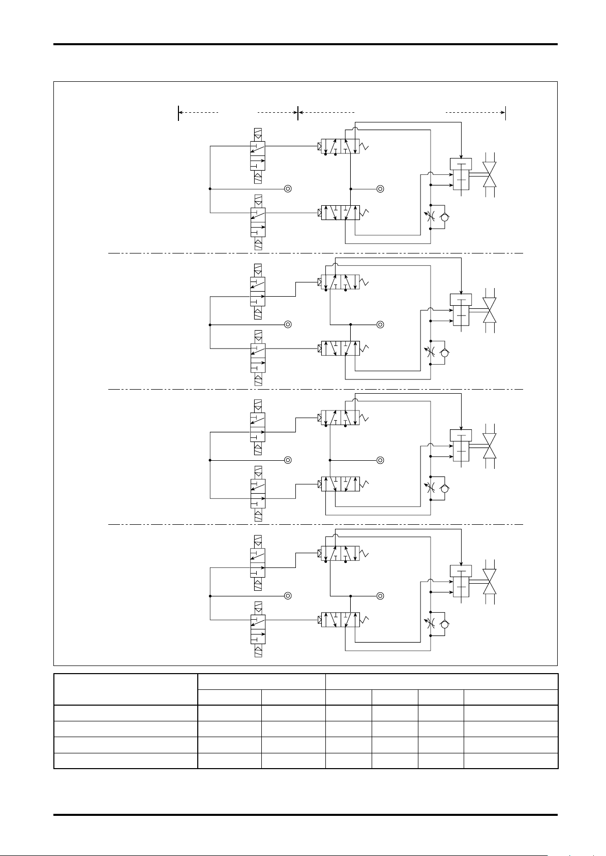
Pneumatic Circuit
LW76E
EXH
EXH
OUT2
IN
OUT1SVMV
V
1
V
2
V
3
EXH
EXH
OUT2
IN
OUT1SVMV
V
1
V
2
V
3
EXH
EXH
OUT2
IN
OUT1SVMV
V
1
V
2
V
3
EXH
EXH
OUT2
IN
OUT1SVMV
V
1
V
2
V
3
IN
IN
IN
IN
Coupled with a double torque cylinder ball valve
<Not in operation>
<Metering under
initial flow control>
<Metering through
fully open valve>
<Metering under
final flow control>
SHUTOFF VALVE
SIGNAL
AIR SOURCE
SHUTOFF VALVE
AIR SOURCE
SIGNAL
AIR SOURCE
SHUTOFF VALVE
AIR SOURCE
SIGNAL
AIR SOURCE
SIGNAL
AIR SOURCE
SHUTOFF VALVE
AIR SOURCE
SHUTOFF VALVE
AIR SOURCE
■
B-320-2-E
Metering Action
Not in operation 0 0 0 0 1 Closed
Metering (initial ow control) 0 1 1 0 1 SV open
Metering (fully open) 1 1 1 1 0 SV, MV open
Metering (nal ow control) 0 1 1 0 1 SV open
Output Signal Shutoff Valve
OUT1 OUT2 V
NOTE: Pressure at individual port
0 - Air pressure not supplied
1 - Air pressure supplied
Fig. 5.4
1
V
2
V
3
Valve position
15
Page 16
B-320-2-E
OPERATION
INDICATOR
RUN, OUT
OPERATION INDICATOR
ALM, COUNT, END
READING
UNITS PLATE
START BUTTON (GREEN)
(▲BUTTON)
STOP BUTTON (RED)
(ROT. BUTTON)
RESET BUTTON (WHITE)
( BUTTON)
▲
LCD DISPLAY
OPERATING BUTTONS
REGISTER
6. ABOUT DISPLAY AND PUSHBUTTONS
6.1 Display Functions
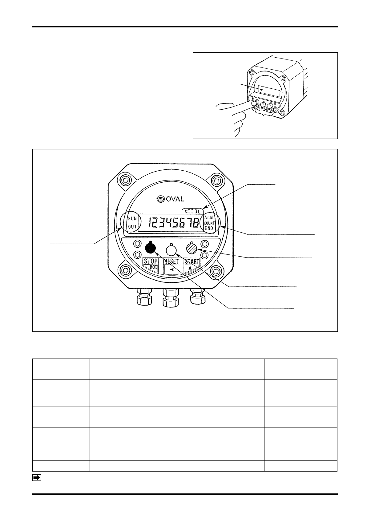
Three pushbuttons - STOP/ROT., RESET/▲ and
START/▲ - are arranged on the front for controlling
a batch process and for setting parameters and
variables. Located in th e c ent er of the di spl ay
assembly is an 8-digit LCD to show characters 12.7
millimeters high.
<Front View of Display>
Fig. 6.1 Pressing a Button
Fig. 6.2
The display is provided with the following functions:
Table 6.1 Operation display function
INDICATION DESCRIPTION
RUN Blinks while the register is in operation. a
OUT
ALM
COUNT
END
Comes on in response to a shutoff valve operation signal
output (MV, SV).
Stays on (missing pulses, excessive overshoot, low
battery alarm) until reset.
Comes on in response to pulses incoming to the total
counter (blinks in synchronism with incoming pulses).
Comes on at the end of a batch process. (Stays on until
the batch setpoint is reset.)
BATT Blinks to indicate a low battery. g
NOTE: For batch setup mode, see paragraph 7.1.1 in page 20.
16
Illuminated segment
(See gure on next page.)
b, c
d
e
f
Page 17
Spring
Pushbutton
Panel
Hex Socket Head Bolt
(M4 × 10 w/spring washer)
Cleansing Spray
RUN
OUT
ALM
COUNT
END
X
L
BATT
a
b
c
d
e
f
g
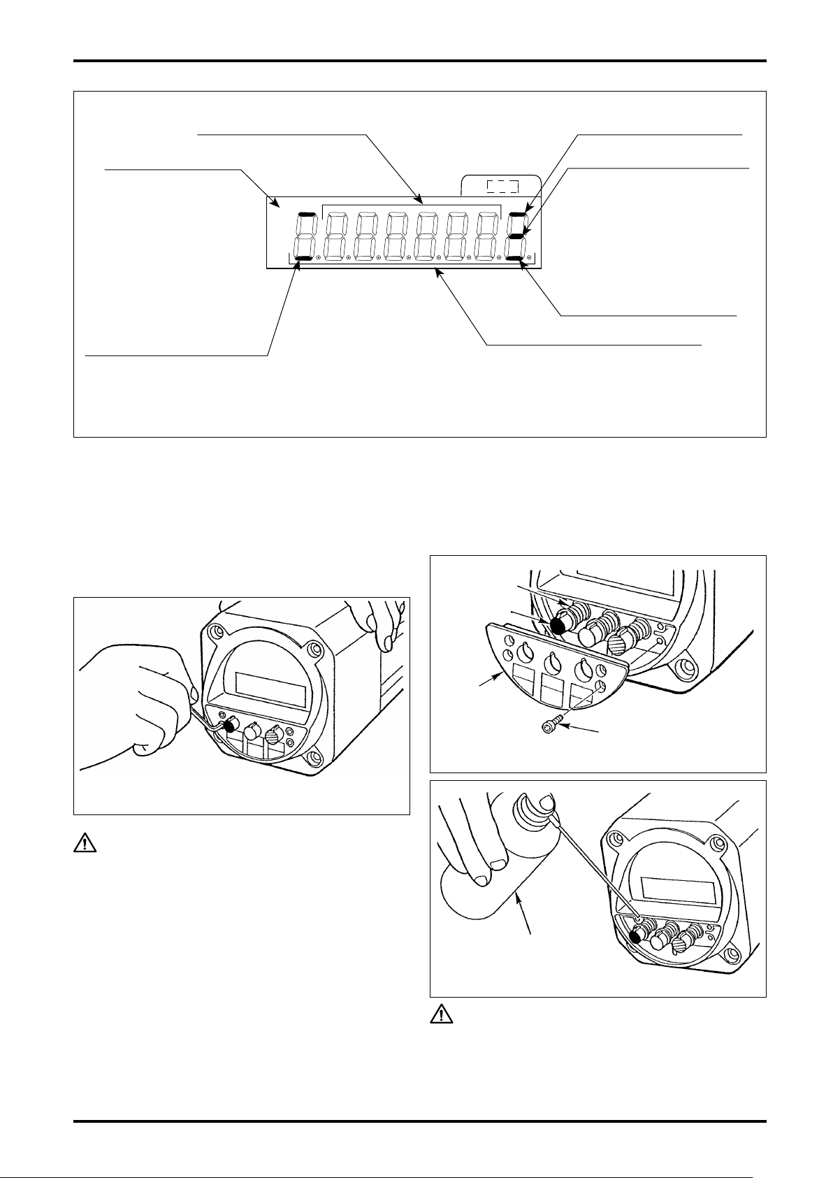
Batch setpoint counter (6-digit)
Flickers to show a low battery
Lights to show an alarm
Lights in response to pulses
arriving at total counter
Lights at the end of a batch
Cumulative total counter (8-digit)
With LW76E (2-step open and close):
1-step open (small valve: SV) Segment c lights in response to an operation signal output → Partially open
2-step open (main valve: MV) Segment b lights in response to an operation signal output → Fully open
Lights in response to a shutoff
valve operation signal output
<LCD Display>
B-320-2-E
Fig. 6.3
6.2 Pushbutton Inspection and Cleaning
Pushbuttons used for operation can be inspected and cleaned by rst removing its semicircular panel, with the
owmeter in the pipeline or not. Be sure to depressurize the air source or remove the front cover to prevent the
shutoff valve from actuation before separating the pushbutton panel.
(1) Take off four hex socket head bolts and remove
the semicircular panel (Fig. 6.4).
Fig. 6.5
Fig. 6.4
CAUTION When separating the
panel, be careful to
prevent pushbuttons and
their springs from coming
off and being lost (Fig. 6.5).
(2) Inspect and clean pushbuttons, their springs, and
(3) F o l l o w i n g i n s p e c t i o n a n d c l e a n i n g , i n s t a l l
button sockets on the part of the register front
cover.
pushbuttons into place according to their colors.
(See pushbutton colors on the previous page.)
CAUTION
1. The panel is made of resin. Tighten bolts at
150cN•m.
2. Avoid immersion of the panel and pushbuttons
in solvent such as thinner, as these parts are
made of resin.
Fig. 6.6
17
Page 18
B-320-2-E
STOP
ROT.
STOP
ROT.
RESET
RESET
▲
START
▲
START
▲
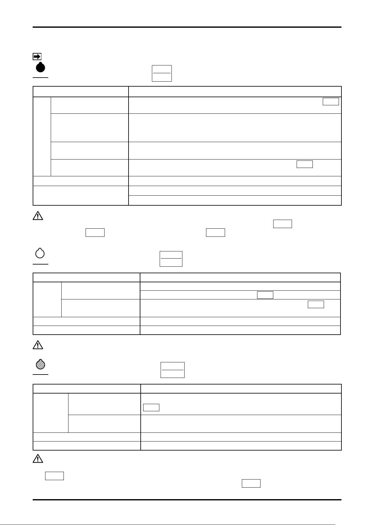
6.3 Pushbutton Functions
NOTE: For pushbutton switch locations, see Fig. 6.2 on page 16.
button (red), internal button
Mode of Operation Functions
A batch in progress.
Batch setpoint (not
operating) or cumulative
total count is displayed.
Batch setpoint is displayed
RUN mode
(not operating)
(batch processing)
Missing ow-signal pulses
detected.
Batch setup mode Establishes a batch setpoint and switches to show the batch setpoint.
Setup mode
Stops the batch process. (Shutoff valve operation signal: stops; LCD
goes out.)
Batch setpoint displayed (6-digit) + RUN status displayed
Cumulative total count displayed (8-digit)
Switches to the batch setup mode (by holding the button depressed for
more than 3 sec. after resetting).
Resets the missing ow-signal pulse detection alarm. (LCD
out.)
Scrolls through the available parameters.
Establishes parameters.
functions
⇔
Displayed alternately (after a reset)
ALM
goes
CAUTION: A switch from batch setpoint display to cumulative total count display is not
acceptable unless the missing flow-signal detection alarm
END
and overshoot detection alarm
ALM
are all reset, and the current batch
ALM
, end-of-batch
setpoint is reset.
OUT
button (white), internal button
Mode of Operation Functions
Batch setpoint is displayed
(not operating).
(batch
An overshoot is detected.
processing)
RUN mode
Batch setup mode Moves the digit to be congured.
Setup mode Moves the digit to be congured.
Resets the batch setpoint (count),
Resets the end of a batch process. (LCD
Resets the missing ow-signal pulse detection alarm. (LCD
goes out.)
functions
END
: goes out.)
ALM
CAUTION: On resetting a batch setpoint, the LCD display will show "0" in the add counter,
and Batch setpoint in the subtract counter.
button (green), internal button
Mode of Operation Functions
Batch setpoint is
displayed
(not operating).
(batch
RUN mode
A batch is in progress.
processing)
Batch setup mode Adjusts a gure (incremental).
Setup mode Adjusts a gure (incremental).
Starts a batch process. (Shutoff valve operation signal produced. LCD
: lights up.)
OUT
Batch setpoint is displayed (for a duration from 5 sec. after start of a
batch process until its end while the button is held depressed).
functions
CAUTION:
Starting up a batch process instantly produces a valve operation signal "SV Open" [LCD
OUT
produces a shutoff valve operation signal "MV Open" [LCD
(bottom): illuminated] whereas, in a model without the 2-step open feature, it
(top): illuminated] at the
OUT
same time.
18
Page 19
B-320-2-E
SW1
ON
1 2
SUB
ADD RUN
SET
SW1−1 SW1−2
NOTE: These terminal are unused.
STOP
/ROT.
RESET/START
/▲
▲
INTERNAL PUSHIBUTTONS
Used for inspection, changing
parameters, etc. with the register front
cover removed.
( )
6.4 Switch Functions
6.4.1 Selecting Add and Subtract Counter
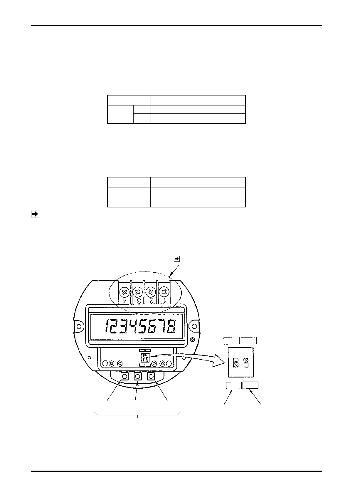
SW-1 in the register internal assembly selects the add or subtract counter.
SW-1 is located at the bottom of the register internal assembly. Set switch SW1-1 to either ADD or SUB.
SW1-2 is a switch for the setup mode. See paragraph 6.4.2.
Table 6.2
Switch Description
SW1−1
Fig. 6.7 shows the SUB (subtracting) counter mode (standard).
6.4.2 Selecting Setup and RUN Mode
SW-2 in the register internal assembly selects the SETUP mode and RUN mode. Set SW1-2 to either RUN or SET.
ON SUB (subtracting) counter (standard)
OFF ADD (adding) counter
Table 6.3
Switch Description
SW1−2
NOTE: *1: Mode to change parameters and cumulative total count.
*2: Normally set in this mode.
Fig. 6.7 shows RUN mode.
ON SETUP mode (SET) *1
OFF RUN mode (RUN) *2
Register Internal Assembly
Fig. 6.7
19
Page 20
B-320-2-E
STOP
ROT.
6 digits
BATCH SETUP MODE
LCD (batch setpoint display) blinks.
To RUN Mode Batch setpoint is illuminated for 2 sec. approx.
NOTE
or
Adjust Figure
Carry
Batch
Setpoint
Set
YES
NO
: To exit from setup mode without changing setpoint.
CHG
In the add counter, following the setup procedure above, the display shows the new
setpoint for 2 sec. approx. and goes back automatically to show "0" (RUN mode).
Set a figure with two
pushbuttons.
START
▲
RESET
▲
STOP
ROT.
STOP
ROT.
STOP
ROT.
7. RECONFIGURATION
In most cases, the pushbuttons arranged on the register front cover do the job (Sec. 7.1). When the register
front cover is removed for parameter changes or inspection, work with internal pushbuttons shown in Sec. 6.3
"Register Internal Assembly".
7.1 Establishing a Batch Setpoint
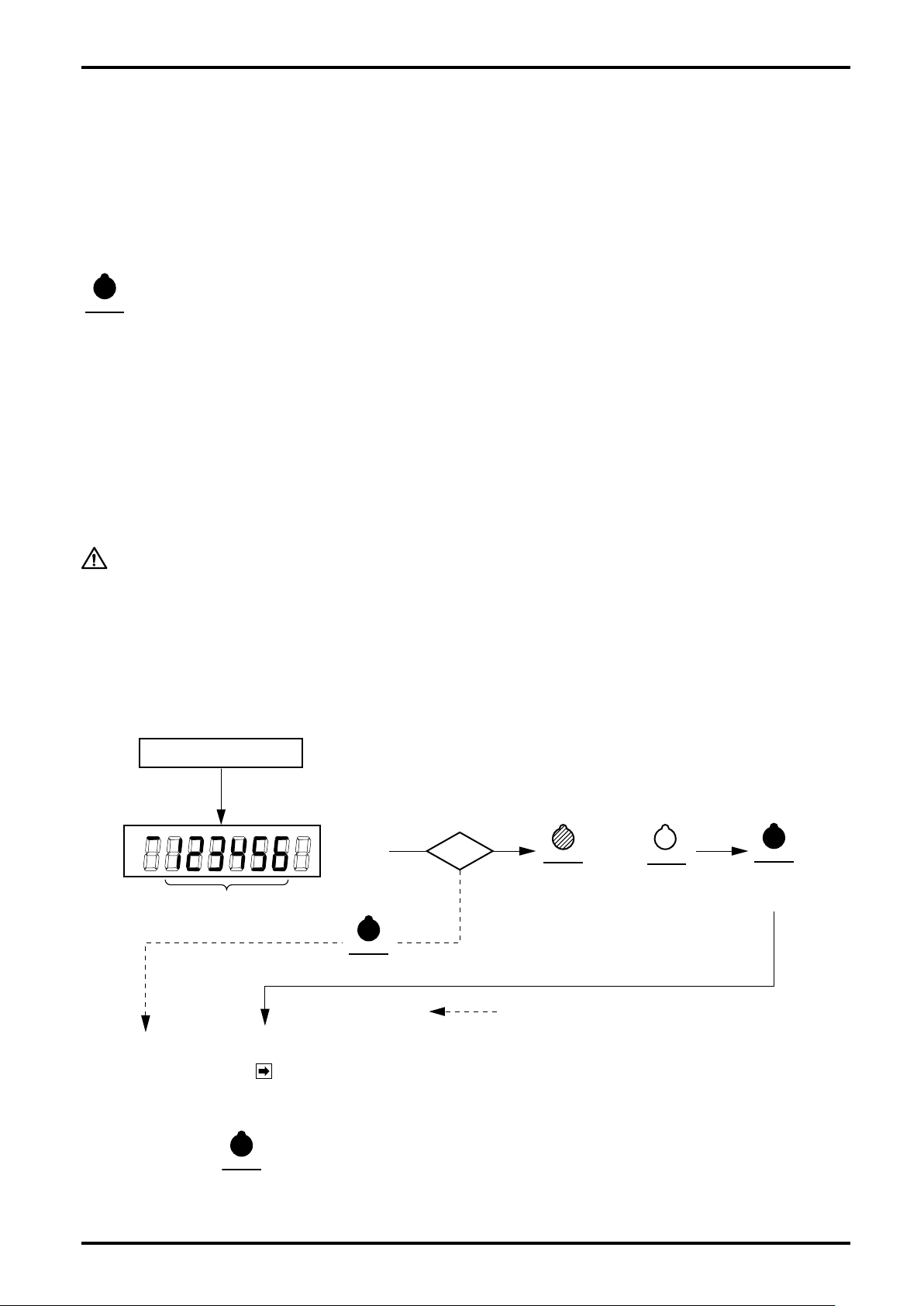
To establish a new batch setpoint, reset, while the LCD shows the batch setpoint, the current setpoint and hold
button depressed for more than 3 seconds. The LCD (batch setpoint) will then begin to blink, indicating
that a new setpoint is acceptable.
Conditions unacceptable for changing batch setpoints
(1) SW1-2 is in the ON (SET).
(2) Cumulative total count is displayed.
(3) Missing pulses have been detected to activate an alarm.
(4) An overshoot has been detected to activate an alarm.
(5) A batch end output is present.
(6) A batch process is in progress.
CAUTION:
1. If an alarm output is present, reset it before changing setpoints.
2. While the register is simply adding up counts of incoming ow signal, other than in a
batch process, then changing batch setpoints presents no problem.
7.1.1 Procedure (batch setup mode)
On seeing the LCD (batch setpoint) blinking in response to the operation above, you can change the current
setpoint by the following procedure.
Upon depression of
button, the gure is stored and the LCD display returns to the RUN mode.
In the batch setup mode, absence of any command with button depressions for more than 10 seconds approx.
causes the LCD to return to the previous setting, bringing back RUN mode automatically.
20
Page 21
7.1.2 Example of Establishing a Batch Setpoint
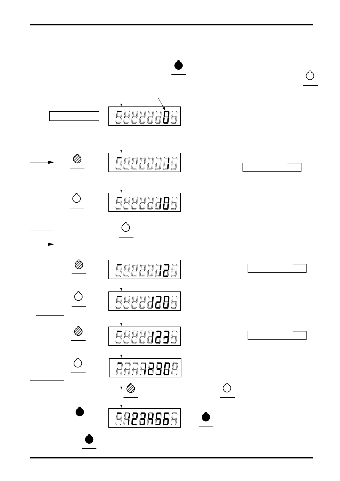
Following resetting the current batch setpoint, hold button depressed for more than 3 seconds.
Press once.
Press once.
Press twice.
Press once.
Press thrice.
Press once.
Press once.
At touch of the figure is stored in the memory and the LCD display returns to the normal batch display.
If you have taken figure place
up more than necessary,
If you have taken figure place
up more than necessary,
Batch Setup Mode
LCD (batch setpoint) blinks.
Previous setpoint blinks.
LCD display: 123 → 1230
LCD display: 120 → 123
LCD display: 12 → 120
LCD display: 10 → 12
LCD display: 0 → 10
LCD display: 0 → 1
Set up from the most
significant digit:
"1" in this example.
Adjust the figure until the LCD displays "123456" and
press to end the setup procedure.
Similarly, keep on adjusting the figure at the rightmost of the LCD with
and taking the figure place up with .
Press the button a number
of times to adjust the figure.
Press the button a number
of times to adjust the figure.
If you have taken the figure place up more than necessary, like
1→10→100, press button a number of times until the
LCD display shows 0 and go back to → to start all over again.
If the figure has gone too far,
→0 →1 →2 …→9
Press the button a number of
times to adjust the figure.
In the operations below, absence of any key entry for
more than 10 seconds will cause the LCD to return to
the previous setting and to the RUN mode automatically.
To change batch setpoints, we recommend to press
a number of times until t he LCD display shows 0 an d
then set up as outlined below.
START
▲
START
▲
START
▲
START
▲
RESET
▲
RESET
▲
RESET
▲
RESET
▲
RESET
▲
RESET
▲
STOP
ROT.
STOP
ROT.
STOP
ROT.
STOP
ROT.
If the figure has gone too far,
→0 →1 →2 …→9
If the figure has gone too far,
→0 →1 →2 …→9
B-320-2-E
●
Shown below is the procedure to set up a batch at 123456 (in the add counter).
21
Page 22
B-320-2-E
SW1
SW1−1 SW1−2
ON
1 2
SUB
ADD RUN
SET
RESET
▲
BUTTON
RESET
▲
SETUP LABEL
RETAINER
7.2 Parameter Setup (cumulative total, scaler factor, frequency division, initial and nal
settings, missing pulse detection, overshoot setting)
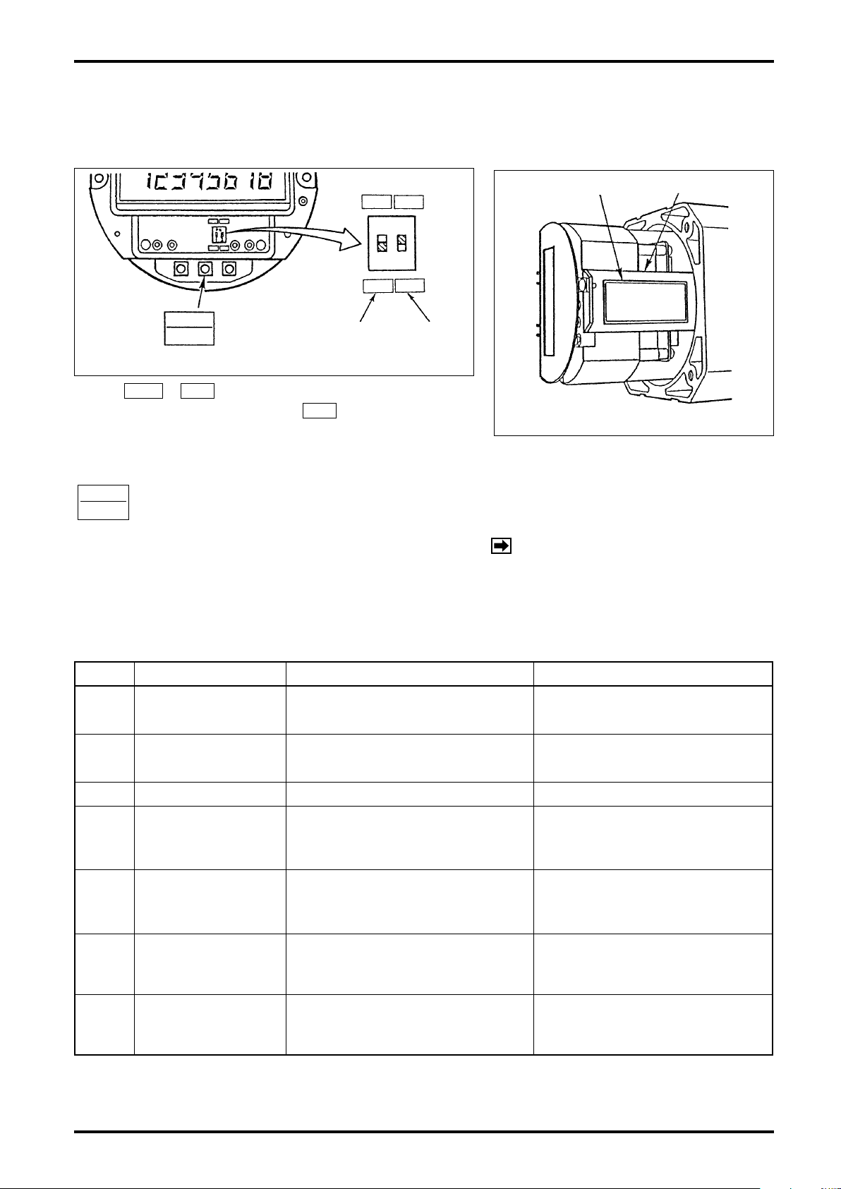
(1) Open the register front cover (see Sec. 9.2 on page 30).
Fig. 7.1
(2) Set
the register internal assembly to
The step taken above brings up the setup mode and the
entire LCD blinks. If the LCD does not blink, press button
Symbol Item Setting Range Default Setting
oP Initial setting
cL Final setting
PL Missing pulse setting
oV Overshoot setting
RUN⇔SET
.
-
F Scaler factor 0.0001 to 1.9999
d Frequency division 0:1/1, 1:1/10, 2:1/100 Default: 0 (1/1)
Total counter reset
(gure adjustment)
switch in DIP switch SW1-2 located in
.
SET
Table 7.1
00000000 to 99999999
0 to 999 counts
(Set to 0: 2-step opening eliminated;
SV and MV open simultaneously.)
0 to 999 counts
(Set to 0: 2-step closure eliminated;
SV and MV close simultaneously.)
0 to 15sec.
(Set to 0: Missing pulse detection
alarm eliminated)
0 to 99 counts
(Set to 0: Overshoot detection alarm
eliminated)
Fig. 7.2
In thi s se tup mode, t he regi ster ca n be
configured to the following variables and
parameters. (Default values appear on the
setup label attached to the retainer inside the
register.)
NOTE: The register is shipped in default
settings unless otherwise
specified by the customer.
---
Meter factor of the owmeter or
customer's specication
With LW76E register: 80
With LW76E register: 80
10
10
22
Page 23
B-320-2-E
OR
Set up a figure
with two pushbuttons.
Adjust Figure Carry Set
Total flow is at 0
Scaler at 1.0000
Frequency divide at 0: 1/1
Initial setting at 80
Final setting at 80
Missing pulse detect
at 10 sec.
Overshoot setting at 10
3-digit
3-digit
2-digit
2-digit
SETUP MODE
NO
YES
LCD blinks
: If you go down to the next step without any
setpoint changes
CUM. TOTAL
RANGE
00000000
to 99999999
SCALER
RANGE
0.0001
to 1.9999
INITIAL
SETTING
RANGE
0 to 999 counts
FINAL SETTING
RANGE
0 to 999 counts
MISSING
PULSE DETECT
RANGE
0 to 15 sec.
OVERSHOOT
RANGE
0 to 999 counts
FREQ. DIVIDE
RANGE
0 TO 2
0:1/1
1:1/10
2:1/100
CHG
START
▲
RESET
▲
STOP
ROT.
STOP
ROT.
OR
NO
YES
CHG
START
▲
RESET
▲
STOP
ROT.
STOP
ROT.
NO
YES
CHG
START
▲
RESET
▲
STOP
ROT.
STOP
ROT.
NO
YES
CHG
START
▲
RESET
▲
STOP
ROT.
STOP
ROT.
NO
YES
CHG
START
▲
RESET
▲
STOP
ROT.
STOP
ROT.
NO
YES
CHG
START
▲
RESET
▲
STOP
ROT.
STOP
ROT.
NO
YES
CHG
START
▲
STOP
ROT.
STOP
ROT.
OR
OR
OR
OR
STOP
ROT.
RESET
▲
START
▲
STOP
ROT.
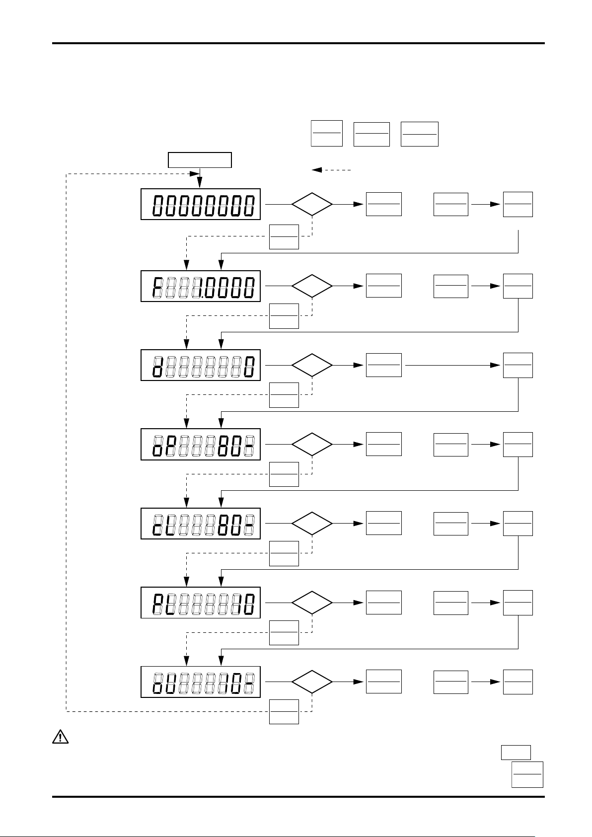
7.2.1 Operation in the Setup Mode
On seeing that the entire front panel LCD is blinking (by the previously outlined steps), you can change
parameters and variables as follows. The procedure to enter a gure remains the same as "An Example of
Batch Setup" in the previous section. Refer to that section.
If the register front cover is removed, use internal buttons:
,
,
1. After all the setup procedure has been completed, set the DIP switch SW1-2 back to
2. Any attempt to set up a gure outside the allowable setting range will fail, upon depression of
CAUTION
button, to change the current setting or shift to the next parameter.
RUN
.
23
Page 24
B-320-2-E
RESET
▲
START
▲
STOP
ROT.
8. OPERATION
8.1 Preparation Before Operation
(1) Ensure that the flowmeter and associated equipment (shutoff valve, etc.) are correctly installed and
connected to the piping assembly with no place left unnished.
WARNING: Make doubly sure that the shutoff valve and this flowmeter are correctly
connected with air tubing.
(2) Thoroughly dehumidify supply air.
Using an air lter, or similar element, drain thoroughly to remove moisture and oil content in the supply air.
(3) Adjust the supply air pressure to the shutoff valve to the specied air pressure with the reducing valve (air
set).
Steps (3) and (4) above require daily inspection.
8.2 Preoperational Checks
CAUTION: Ensure that, without allowing the process fluid to run, the shutoff valve
operates positively and that no air leaks exist at air tubing connections.
(1) Set the quantity of a batch to any value.
NOTE: See Section 7 on page 20 for setup procedure.
(2) Show the batch setpoint in the LCD display, press
make certain that the shutoff valve opens.
(3) Press
(4) Repeat steps (2) and (3) above several times to make sure of correct shutoff valve opening and closing.
button (red) to conrm that the shutoff valve closes.
button (white), and then
button (green) to
CAUTION: Be sure to run an operation check above with front cover in place.
24
Page 25
B-320-2-E
SHUTOFF
VALVE
BYPASS LINE
FLOW
METER
STRAINER
VALVE
FLOW DIRECTION
A
B
C
EXCESSIVE
FLOW
RAPID FLOW
VARIATION
RAPID TEMPERATURE CHANGES
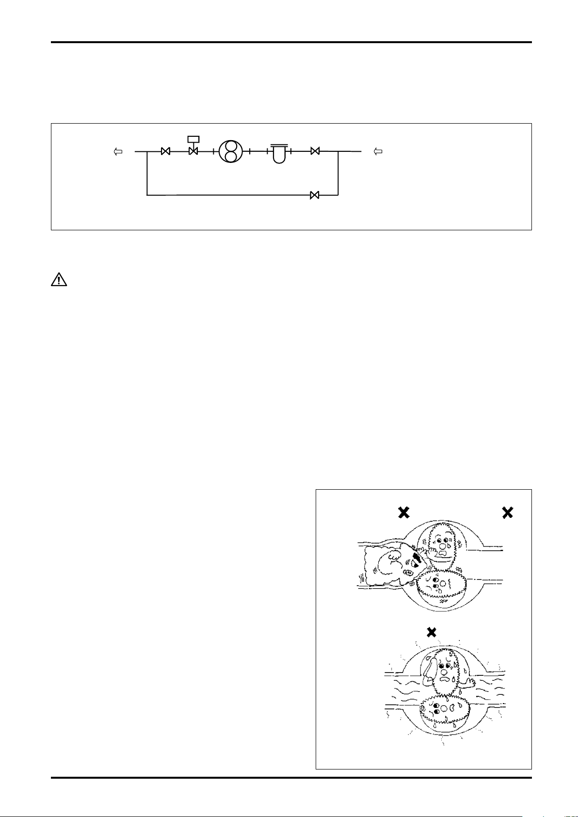
8.3 Operation with Actual Flow
At rst-time operation with actual process uid, careful observation of operations sequence which is described
below is required. It is essential that the owmeter be used within the specied ow range.
(⇩Refer to the piping diagram below.)
Fig. 8.1
(1) Shut off the valve (A) on the inlet side and the valve (B) on the outlet side and then open the bypass line
valve (C) to allow the uid in the bypass line, thereby removing weld chips, scale and other foreign solids
left in the piping assembly.
CAUTION: This is particularly important in a newly installed piping assembly.
(2) Open the shutoff valve manually. If it is hard to open it manually, set the missing pulse setting to "0", select
any batch setpoint and press the START button.
(3) Carefully and slightly at rst, open the valve (A) upstream of the meter progressively and then, slightly at
rst, open the valve (B) downstream of the meter progressively.
(4) Slowly close the bypass line valve (C) and make sure that the total counter in the register advances in
response. Maintain a owrate 10 to 20% of the maximum owrate in this state, allow the ow to run for
more than 15 minutes and make sure that air in the piping assembly has totally escaped.
In applications where temperature exceeds 60°C, run the system at least for 30 minutes in this state to
ensure uniform heat distribution in the measuring chamber (preheating is necessary).
(5) Following the break-in (preheating) period, shut off the bypass line valve (C) completely and open the
upstream valve (A) progressively until fully open and slowly open the downstream valve (B) until the rated
ow is reached.
(6) Flowrate should be regulated with the valve (B) downstream of the meter and should be held within the
specied rating.
8.4 Operating Precautions
(1) When changing owrates:
In applications where the owrate varies or where
shutoff valve opening and closure takes place in
batch operation, avoid rapid changes in flowrate
across the meter.
Op erating the mete r a t flowra tes in exce ss of
the maximum allowable flowrate will nullify the
guaranteed accuracy, reduce the meter life and
may result in faulty conditions, such as the seizure
of bearings or the rotor-to-measuring chamber
contact.
(2) Where the temperature of metered uid changes:
Avoid rapid temperature changes in the meter.
Temp erature c hanges of the fluid in the meter
should be held within 3°C per minute.
Extra care should be used particularly when making
a flow measurement in batch operation without
the provision of heat tracing of the piping where
the fluid temperature differs from atmospheric
temperature.
If rapid temperature changes are anticipated, heat
trace the piping assembly as well as the meter.
Fig. 8.2
25
Page 26

B-320-2-E
TAKE PRECAUTIONS
AGAINST
BEARING BURNING!
(3) Liquids of low steam pressure
Temperature and pressure of LPG, polyvinyl
chlorid e mo n o m e r s or anything wi t h l o w
viscosity and low steam pressure that are prone
to vaporize should strictly be controlled.
During operation, the temperature of bearings
in the meter is usually higher than that of the
met ere d fl uid. Vapo rs a rou nd t he b eari ngs
can be causes of faulty conditions, including
generation of unusual noise and bearing burn.
(4) Corrosive liquids
When y o u ma ke a me a s u remen t o f highl y
corrosive liquids, such as nitric acid and sulfuric
acid, appropriate materials should be used for
ta nks and piping assembl y. Heteroge neous
materials originally contained in the metered uid
or corrosive substances dissolved from tanks
and pipes of inappropriate materials may lead
to costly downtime, as a result of locked rotors,
for example, when they are allowed into the
measuring chamber.
Fig. 8.3
CAUTION
8.5 Precautions at Operation Shutdown
(1) Valves should be closed progressively.
Rapid valve closure could, under certain piping conditions, cause a sharp pressure rise by water hammer,
or hydraulic shock, resulting in damage to the meter.
(2) Precautions against pressure buildup on closure
Complete closure of valves upstream and downstream of the meter makes the affected section a totally
enclosed chamber and a pressure buildup inside due to the rise of atmospheric temperature could lead to
an unexpected damage to the meter.
(3) Liquids ready to adhere or gel at zero ow velocity
Liquids that tend to adhere and solidify or gel at ow velocities around zero must thoroughly be washed
away from the meter interior with running cleaning uid before shutdown. Negligence of this instruction
may leave the meter as an immovable unit when the operator attempts to resume meter operation the next
time.
8.6 Strainer Inspection
The strainer net should be inspected for condition and cleaned on a regular basis.
In a newly installed piping system, in particular, inspect daily rst and, according to the degree of clogging of
the net observed, the time interval for inspection may be reduced progressively to, say, once a week.
26
Page 27
B-320-2-E
: Normal operation
: In an emergency or in trouble
LCD display to shown batch setpoint
From in
next page
To in
next page
RUN
OUT
ALM
COUNT
END
X
L
RUN
OUT
ALM
COUNT
END
X
L
RUN
OUT
ALM
COUNT
END
X
L
Resetting a batch setpoint
NOTE: Shows the batch setpoint in the subtracting
counter, or shows "0" in the adding counter.
Starting a batch process
- Shutoff valve opens (1st step)
Initial setting at "0": Fully opens.
Initial setting other than "0": Partially opens.
- lights up.
Initial setting at "0": Top and bottom light up.
Initial setting other than "0": Only bottom lights up.
- Starts counting ( blinks sync with count.)
Reaching the initial setting (LW76E register equipped model only)
- Shutoff valve opens (2nd step).
Initial setting other than "0": Fully opens.
- lights up.
Initial setting other than "0": Top and bottom light up.
Interrupting a batch process
- Shutoff valve fully closes.
- goes out.
OUT
OUT
OUT
COUNT
A B
START
▲
RESET
▲
STOP
ROT.
STOP
ROT.
8.7 Starting a Batch Process
8.7.1 Preoperational Checks Before a Batch Process
When you are through with all the preparations described in the previous sections, perform the following
checks:
(1) Parameters, batch setpoint, adding or subtracting counter mode are correctly established (see Sec. 7 or
Sec. 6.3)
(2) DIP switch SW1-2 is in the RUN mode (see Sec. 6.3).
(3) Register front cover is properly installed on the register body.
CAUTION: Unless the register front cover is installed in place, the pushbuttons in
the front may not function properly.
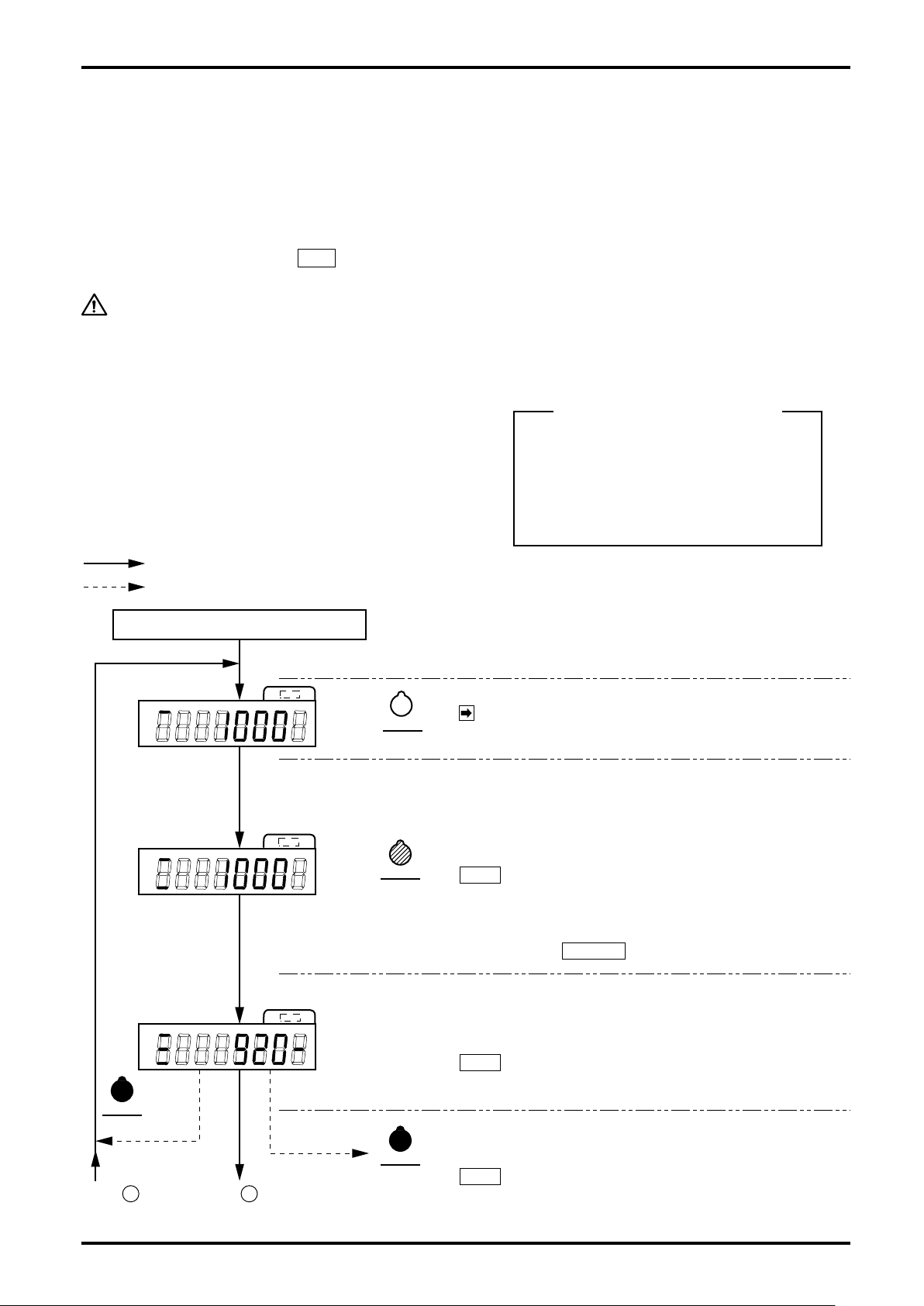
8.7.2 Starting a Batch (procedure)
Behavior of the LW76E register equipped meter is
described below, using a setup operation for the
target batch setpoint and parameters shown in the
box on the right as an example.
Example of batch setpoint and
parameter setup
- Batch setpoint: 1000 counts
- Initial setting: 80 counts
- Final setting: 80 counts
- Overshoot setting: 10 counts
27
Page 28
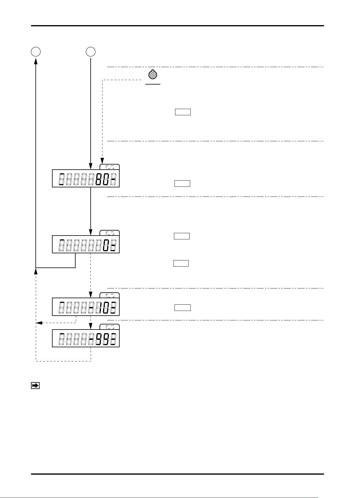
B-320-2-E
RUN
OUT
ALM
COUNT
END
X
L
RUN
OUT
ALM
COUNT
END
X
L
RUN
OUT
ALM
COUNT
END
X
L
RUN
OUT
ALM
COUNT
END
X
L
Starting a continual batch process
- Shutoff valve opens.
When interrupted while shutoff valve was fully open:
Restart at full open.
- lights up.
When interrupted while shutoff valve was fully open:
Top and bottom light up.
Reaching the leading edge of final setpoint before target batch
setpoint (LW76E register equipped model only)
- Shutoff valve closes (1st step).
Final setting other than "0" : Partially closes.
- goes out.
Final setting other than "0" : Only top goes out.
Reaching the batch setpoint
- Shutoff valve closes (2nd step).
Final setting at "0" : Fully closes.
Final setting other than "0" : Fully closes.
- lights up.
Final setting at "0" : Top and bottom go out.
Final setting other than "0" : Top and bottom go out.
- lights up. (Normally stops counting after several
additional counts as an overshoot upon completion of a
batch process.)
Overshoot detection
- lights up.
If count still continues.
- In the subtracting counter, indicates up to – 99 counts.
OUT
OUT
OUT
ALM
A B
END
START
▲
NOTE: (1) Reaching the batch setpoint means, in the subtracting counter, the moment the total reading
has reached 0 or, in the adding counter, the total reading has reached the target batch setpoint.
(2) Batch counter display (6-digits) shows, in a subtracting counter, a negative figure below 0,
continues counting down to -99 counts and stops counting.
Above 999999 counts in the adding counter, it returns to 0 and continues counting.
(3) Cumulative total counter (8-digits) keeps adding up counts, whether adding or subtracting,
returns to 00000000 beyond 99999999 and continues counting.
28
Page 29
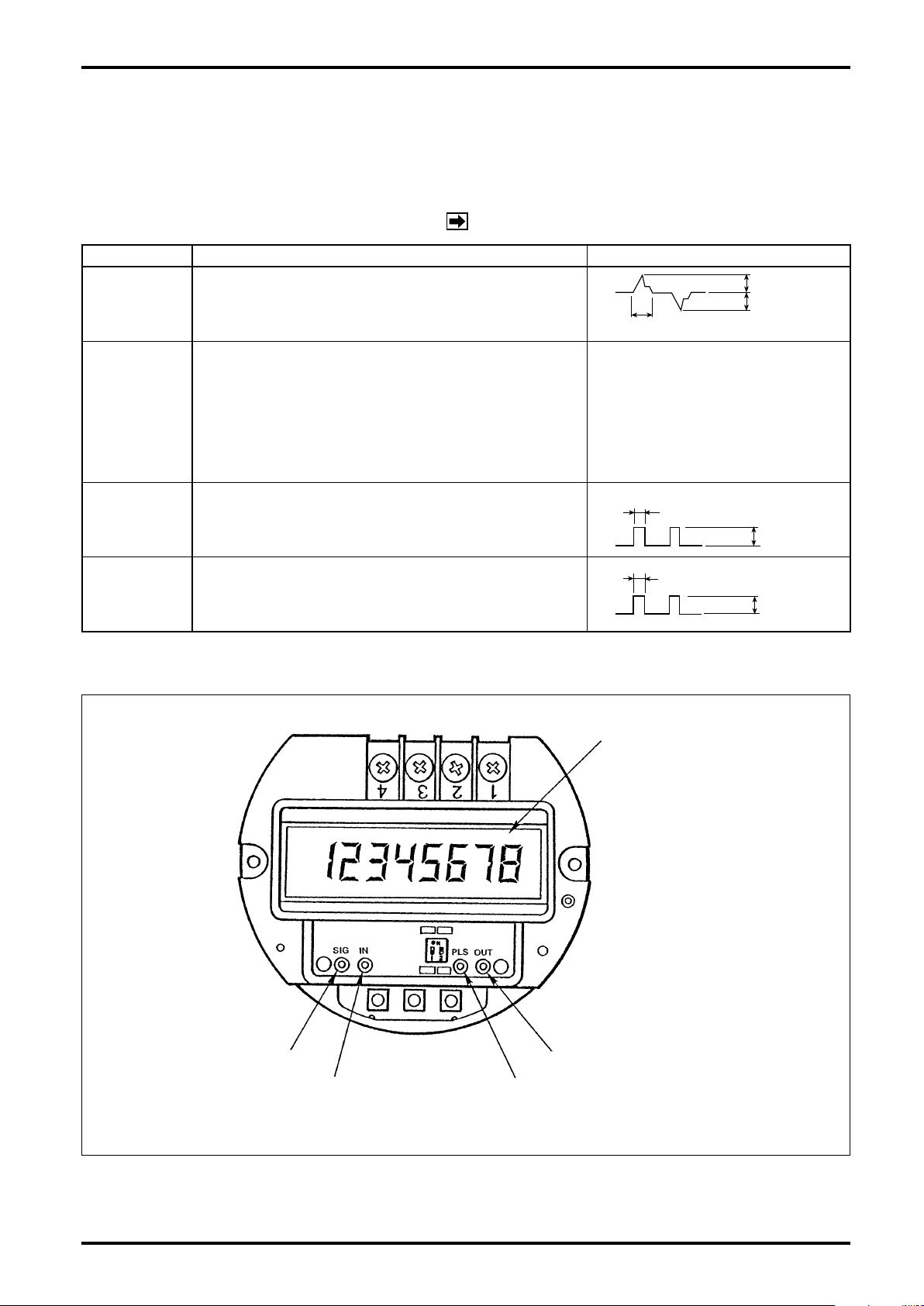
9. INSPECTION
10μs
200mV
200mV
2 to 2.5ms
3V
Pulse frequency ≤ 200Hz
1 to 1.5ms
3V
LCD DISPLAY
SIG PIN
IN PIN
PLS PIN
OUT PIN
9.1 Register Inspection
Test pin functions
●
(Show waveshapes while the uid ows)
NOTE: The register housing serves as 0V (common).
PIN NAME FUNCTION WAVEFORM
SIG An amorphous sensor output waveform appears.
Accepts a simulated pulse train from the pulse
checker (OVAL Model PC2201, for example).
IN
PLS
Used for making a loop check or other servicing.
Input mode is Model PC2201's PG30 mode. Also
accepts pulses with levels "0": 1V max. and "1": 3 to
12V, or open collector.
A rectangular waveform after waveshaping the SIG
pulse waveform. Output timing remains the same as
that of SIG.
B-320-2-E
OUT
Produces a factored pulse output with the same
timing as that of the indicated count.
Fig. 9.1 Test Pins on the Front of Register’s Internal Assembly
29
Page 30
B-320-2-E
REGISTER
SCREWS
REGISTER
FRONT COVER
INTERNAL ASSEMBLY
BATTERY
PACK
REGISTER BODY
REGISTER FRONT COVER
INTERNAL ASSEMBLY
FACE PLATE
90°
HOLD-DOWN STRIP
RETAINER
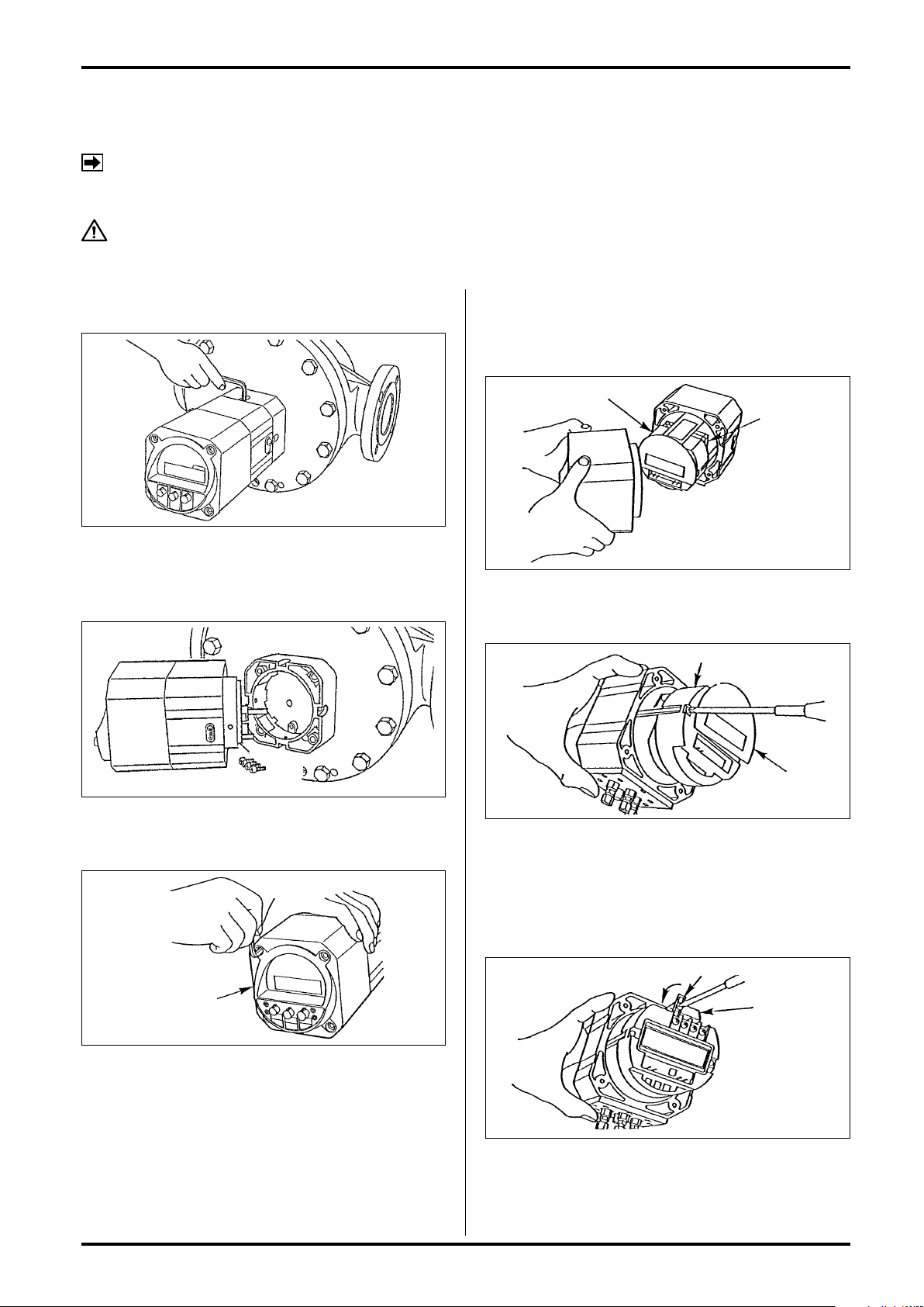
9.2 Register Disassembly
When you inspect or replace subassemblies, follow the procedure given below.
NOTE: 1. Size 29 single-case construction meter is shown here. The same procedure applies to other sizes.
2. Removing only the internal assembly, battery pack, solenoid valve unit, or sensor unit does not
require steps (1) and (2).
CAUTION: Stop supply air to the shutoff valve and disconnect air signal lines
beforehand.
(1) Take off four hex socket head bolts on register
sides, using hex wrench key.
(2) Carefully draw the register assembly out. Do so
in a straight line, exercising care not to bump the
sensor unit.
(4) Separate the register front cover from the register
body in a straight line carefully. (Use care not
to bump the front cove r aga inst the i ntern al
assembly.)
(5) Take off two screws (M4) securing the internal
assembly, using screwdriver.
(3) Take off four hex socket head bolts (M8) on the
front of register, using hex wrench key.
30
(6) Loosen #4 terminal screw and retainer screw of
the internal assembly with screwdriver and slide
the hold-down strip upward with screwdriver. To
prevent the hold-down strip from missing, turn it
90 deg. and install to the retainer again.
Continued on next page.
⇨
Page 31
B-320-2-E
INTERNAL ASSEMBLY
BATTERY PACK
HEXAGONAL POSTS
COUPLING
BUSHING
SOLENOID
VALVE UNIT
HOLD DOWN STRIP
RETAINER
SOLENOID VALVE ASSEMBLIES
LW76E REGISTER SERVICE
SENSOR
RETAINER
SENSOR
CONNECTOR
SENSOR
RETAINER
FITTING
SCREW
158 152
SENSOR ASSEMBLY
SENSOR FITTING
DISC
SENSOR OPENING
FOR SINGLE-CASE
METER
SENSOR OPENING
FOR DOUBLE-CASE
METER
FLOW DIRECION ARROW
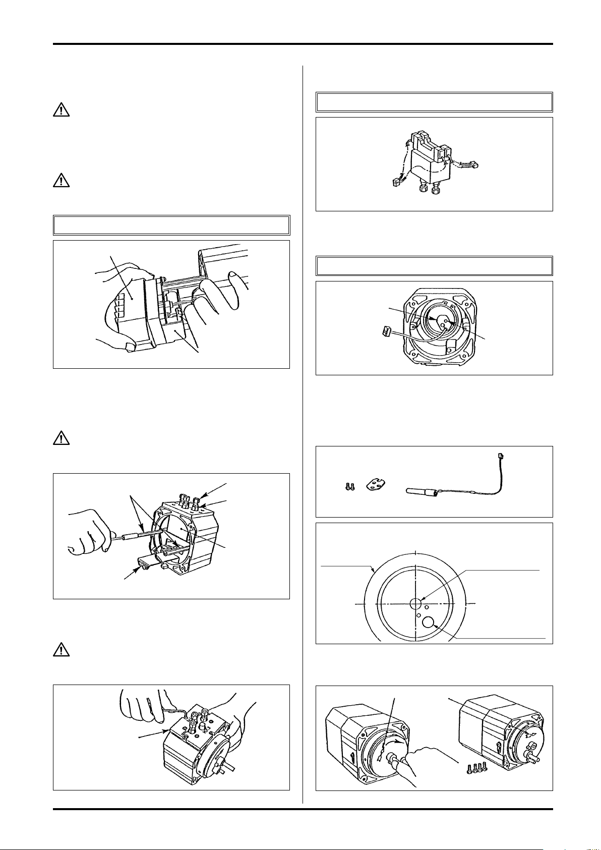
(7) Pull the internal assembly a little forward and
remove connectors CN1, CN2-1 (SV), and CN2-2
(MV) at the bottom of the battery pack.
CAUTION: With LW74E register,
CN2-2 (MV) is unused. At
reassembly, be careful
not to make a mistake in
connections.
CAUTION: Do not pull the sensor
bracket forcibly, or its
lead wires may break.
Now the internal assembly is ready for
removal.
(10) Draw the solenoid valve unit out of the register
body.
Now the solenoid valve is ready to be removed.
(11) Loosen sensor retainer tting screws (M4) with
screwdriver, remove the sensor retainer and
draw out the sensor unit.
The sensor unit is now ready to be removed.
(8) Remove the two posts securing the hold-down
strip with socket wrench.
Then remove three couplings at air connections
and silencer from their bushings.
CAUTION: Do not take a firm grip of
the silencer overmuch or
it will be crushed.
(9) Take off eight hex socket head bolts (M4) holding
the retainer, using hex wrench key.
CAUTION: At installation, tighten bolts
in an alternating order to
ensure even tightening.
(12) Insert a new sensor unit into the opening through
which the old sensor was removed. Assembly
is simply the reverse of the removal procedure.
Upon comp let ion of assemb ly, pe rform an
operation check before service operation.
Location of Holes for Installing the Sensor
(13) At register installation on the body, ensure that
the ow direction arrow on the body agrees with
the arrow mark on the sensor bracket.
31
Page 32
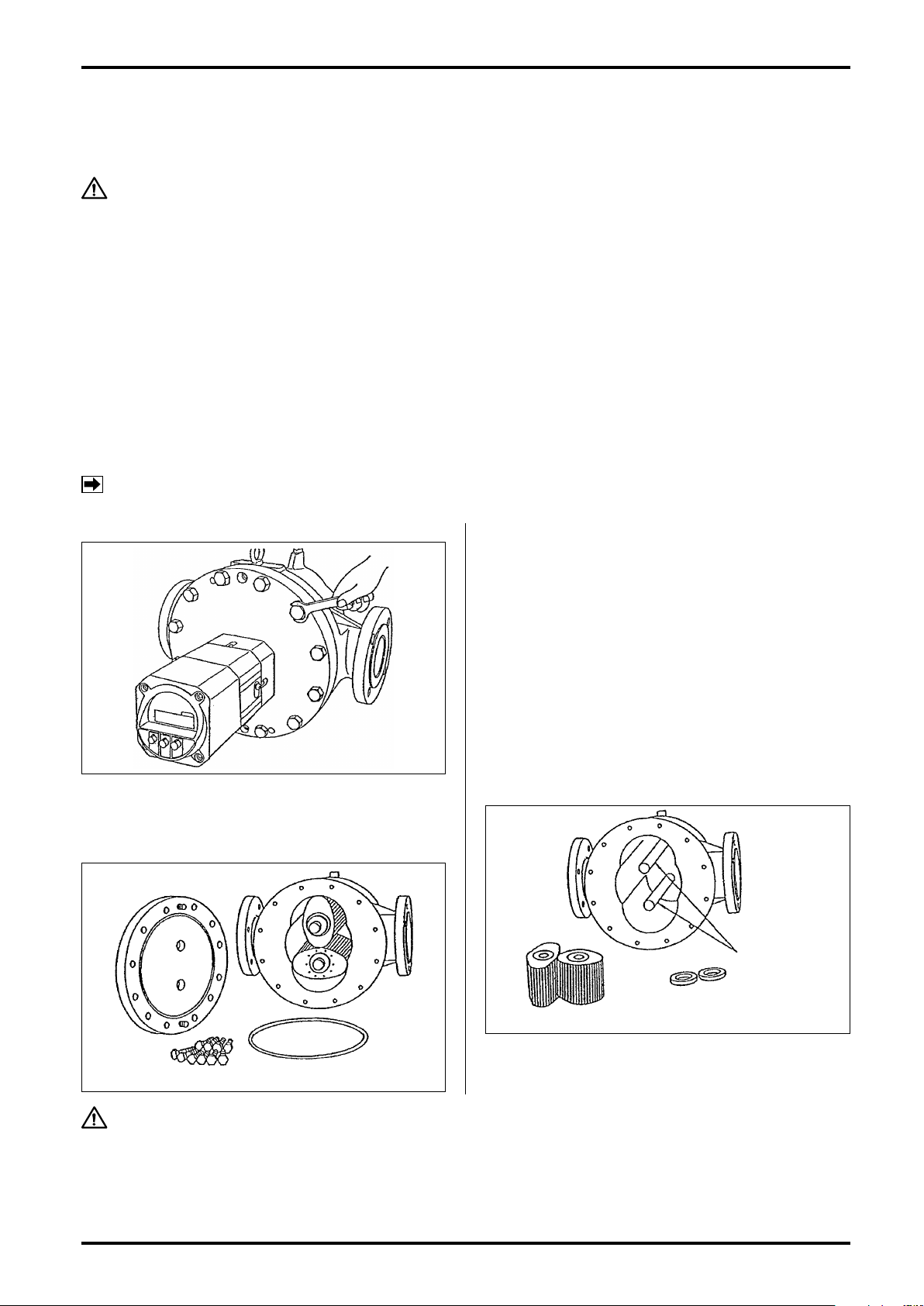
B-320-2-E
ROTOR SHAFTS
METER BODY
ROTORS
THRUST RINGS
FRONT COVER
O-RING
HEX BOLTS
9.3 Meter Body Disassembly and Inspection
Although it depend on individual operating conditions, periodic disassembly and inspection should
◎
be performed at least once a year.
CAUTION: Because the Oval flowmeter is a precision industrial instrument,
disassembly and inspection should be performed indoors as a rule. If
it is desired to disassemble and inspect it as installed in the field, an
important precaution to remember is to reduce the internal pressure
of the piping assembly to a safe level, shut off valves upstream and
downstream of the meter completely, drain the piping assembly and
then place a suitable fluid receptacle directly below the flowmeter.
Exercise care to keep each component disassembled free from grit and
dust.
- Meter Inspection
When the uid does not ow through the meter, the oval rotors might be stuck with scales, resulting in
stop of their rotation.
9.3.1 Single-case Construction Meter Body Disassembly and Inspection
NOTE: Size 29 single-case construction meter body is shown here. The same procedure applies to other
size meters.
(1) Take off all the twelve hex bolts (105), using wrench.
(2) With the front cover removed, the measuring
chamber with oval rotors and other components
are accessible.
(3) Remove oval rotors from the measuring chamber
and inspect them for condition. (Rotor shafts
should be drawn out straight forward.)
(a) Inspect the oval rotors to see if they are stuck
with foreign solids.
(b) Check the rotors, shafts and other components
for wear.
(c) Inspect the measuring chamber and the inner
wall of front cover for damage or any other
sign of unusual condition.
Upon completion of these inspections, clean the
oval rotors, rotor shafts, measuring chamber and
front cover with clean water or suitable solvent
thoroughly.
1. Deep scratches, high spots due to impressions, or other aws should be reconditioned at
2. If the areas which have been forcibly in contact with front cover jacking bolts are distorted
3. Excessive reconditioning may result in a loss of meter accuracy.
32
CAUTION:
with oil stone or other tool.
outwardly, recondition it at with oil stone.
Page 33
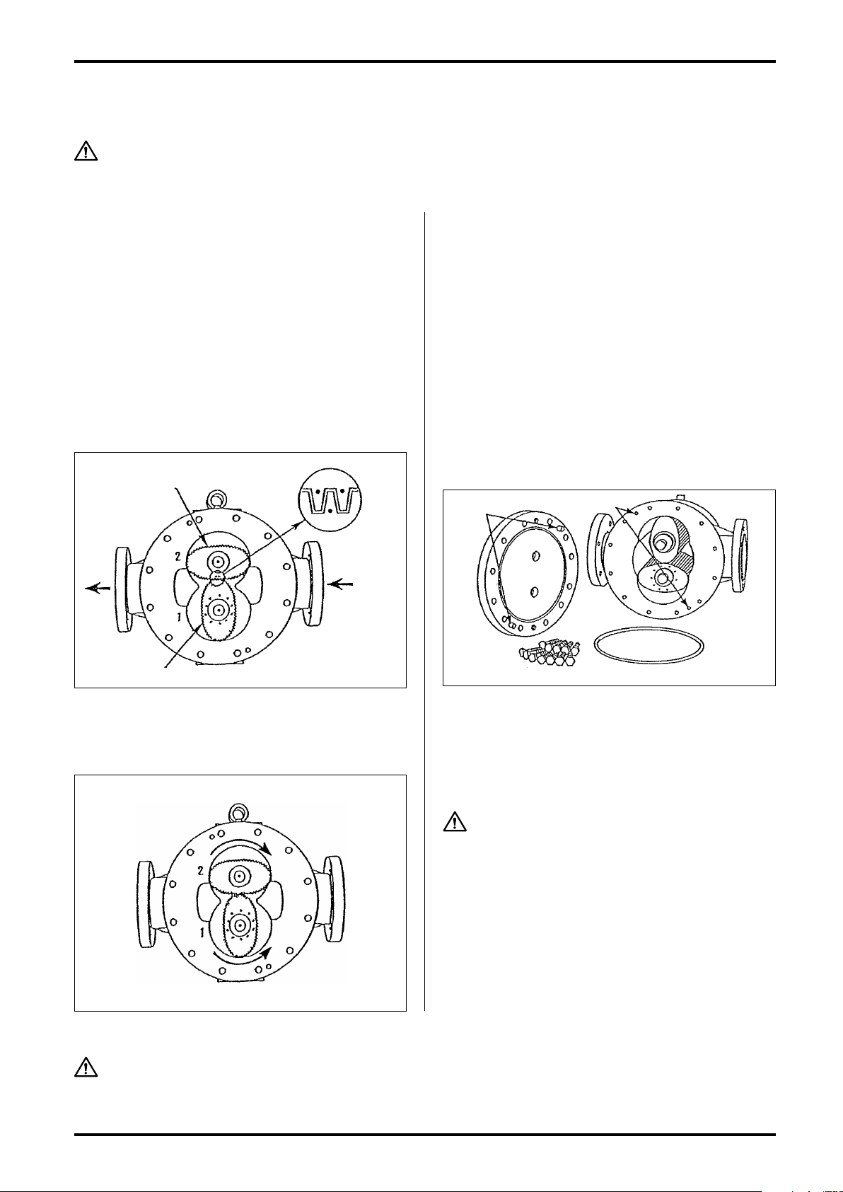
B-320-2-E
PIN SLOTS
PINS
HEX BOLTS O-RING
2ND ROTOR
MATCH MARK
FLOW
DIRECTION
INOUT
1ST ROTOR SIGNAL MAGNET
9.3.2 Single-case Construction Meter Body Assembly Procedure
SERVICE NOTE BEFORE ASSEMBLY
◆
Oval rotors, inner walls of the rotor shafts, inner wall of the measuring chamber, inlet and
outlet ports, and inner surface of the front cover should be thoroughly washed clean,
completely removing dust.
◆
(1) Rotor Installation
Rotor installation is correct if the side where
signal generating magnets are embedded faces
the register (top of the measuring chamber) and
the side with match marks ( • )( •• ) faces the
front cover.
Carefully install the rotors with the 1st rotor
(match mark "•") on the shaft with "1" stamped
on the outside of measuring chamber and the
2nd rotor (match mark "••") on the shaft with "2"
stamped. Ensure that the match marks are as
shown in the inset.
(3) Front Cover Installation
Firstly install O-Ring (103) on the front cover. If
the O-Ring is damaged or swollen with metered
liquid, it will not t in the groove. If such is the
case, replace with a new one.
Align the locating pins of front cover with its
pin slots in the meter body and, tting the rotor
shafts into rotor shaft sockets in the front cover,
force the meter body until the locating pins fit
rmly into the pin slots in the meter body without
slanting the front cover. Install 12 hex bolts (M16)
and tighten them evenly until the front cover is
closely in contact with the meter body.
(2) Make sure of the smooth rotation and correct
engagement of the rotors by rotating them with
hand.
(4) Conrming Smooth Rotation
With air or water, mak e sure to see t hat t he
rotors move freely.
CAUTION
Rotation check should be performed at
low rotor r.p.m.
Violent rotor spinning may cause a
damage to the components, and bearing
burn.
CAUTION:
This meter is not compatible with any other registers. Never attempt to replace it.
33
Page 34
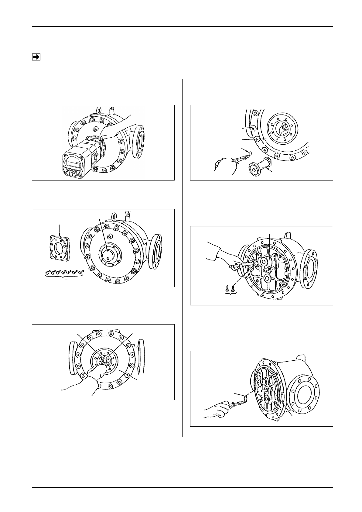
B-320-2-E
119
102
254
253
204
218
216
214
124
125
253
253
254
102
9.3.3 Double-case Construction Meter Body Disassembly and Inspection
NOTE: Sizes 28 and 29 double-case construction meter body is shown here. The same procedure applies
to other size maters.
(1) Using hex key, take off four bolts (115). Holding
the register assembly in both hands, carefully
separate it from the meter body.
(2) Using hex key, take off eight bolts (125) and
remove sealing ange (124)
(4) Remove the signal generating magnet assembly.
Take off 16 stud bolt nuts (119) and the front
cover is ready to be separated.
(5) Take off four hex bolts (218) and use two of them
in the threaded jack screw holes in the major
shaft holder (204) to jack the major shaft holder
by tightening them alternately as shown.
(3) Using stop ring pliers, remove stop ring (254). At
assembly, install part (253) and then tighten front
cover (102).
(6) Using stop ring pliers, remove stop ring (216)
and remove uniform-motion drive gear (214). At
assembly, install in line with the locating pins of
uniform-motion gears.
34
Page 35
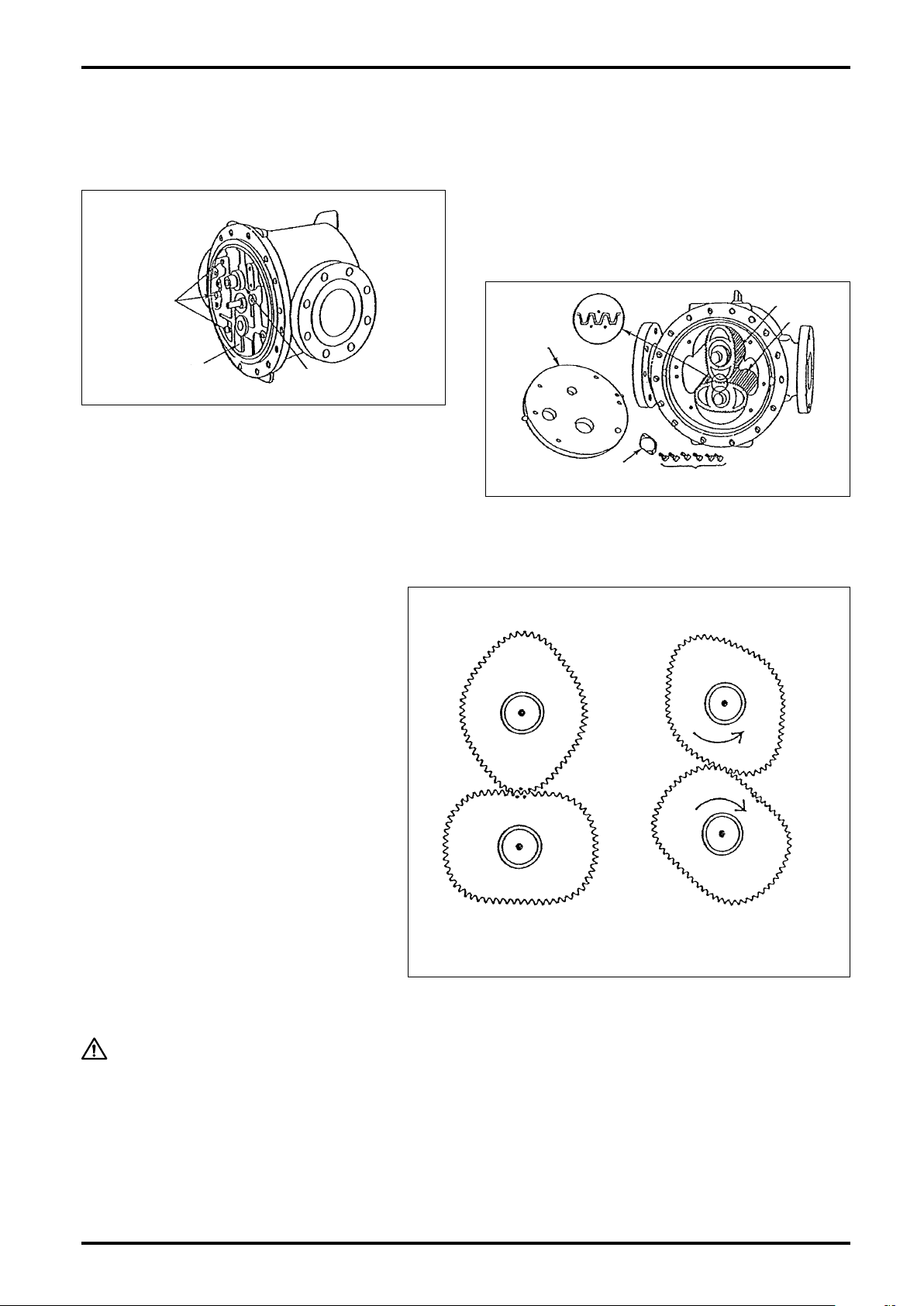
B-320-2-E
217
202
214
DRIVE UNIFORM-MOTION
GEAR
DRIVE UNIFORM-MOTION
GEAR
FOLLOWING
UNIFORM-MOTION GEAR
(SIGNAL MAGNET EMBEDDED)
FOLLOWING
UNIFORM-MOTION GEAR
(SIGNAL MAGNET EMBEDDED)
202
214
217
209
208
(7) Using hex key, take off six bolts (217) and use
two of them in the threaded jack screw holes in
the inner case top cover (202) to jack the inner
case top cover by tightening them alternately.
(8) N o w t h e m e a s u r i n g c h a m b e r i s r e ady fo r
inspection.
Wash clean the oval rotors, measuring chamber,
and inner case top cover with suitable cleaning
oil. Reassemble them exercising care to keep grit
and dust from entering.
At assembly, align match marks as shown and
make sure of smooth rotor rotation.
9.3.4 Double-case Construction Meter Body Assembly Procedure
Assembly is the reverse of the removal
proced ure , b ut o bser ve the foll owi ng
instructions.
Illustrated at right is the way the uniformmotion gears are assembled.
At assembly, careful attention must be
paid to the proper engagement of uniformmotion gears. In line with match marks,
slide the arrow marks as shown. Following
gear engagement, be sure to make one
co mplete revolutio n to ensure smoot h
rotation.
CAUTION: This meter is NOT Compatible with any other registers. Never attempt
to replace it.
35
Page 36
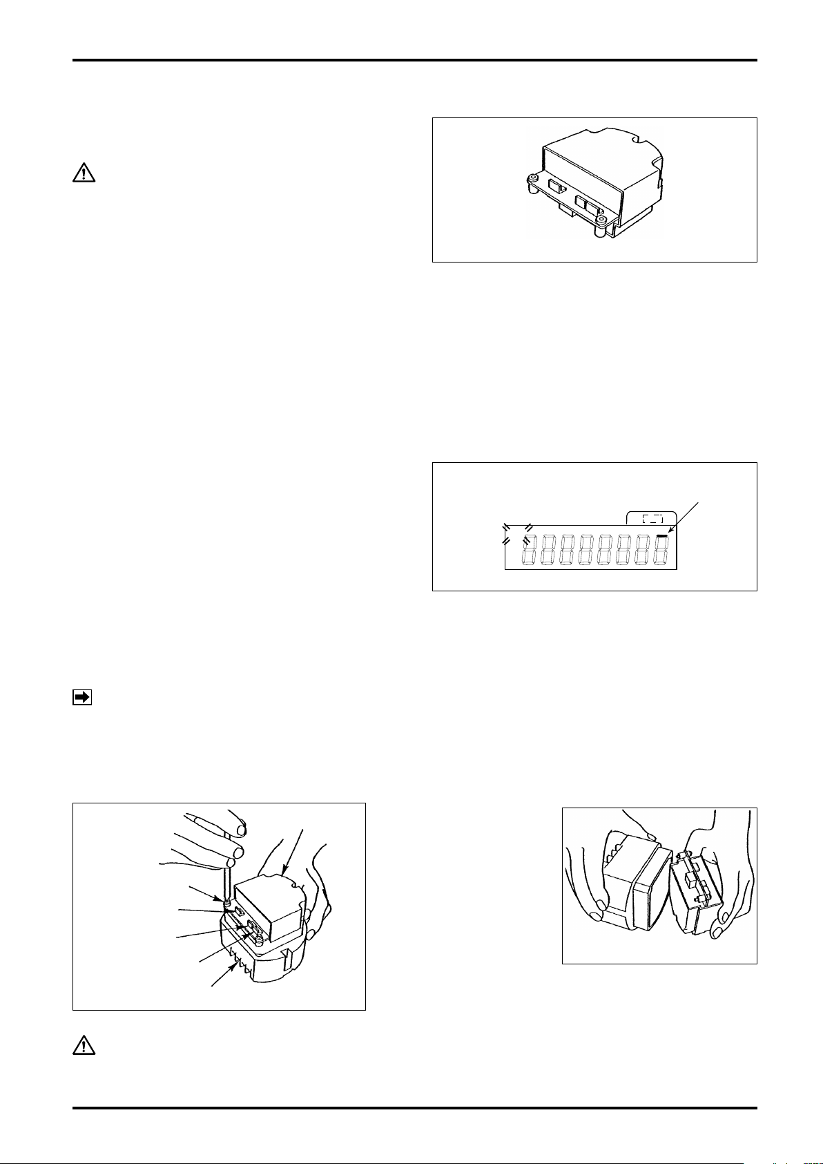
B-320-2-E
BATTERY PACK
FITTING SCREW
INTERNAL ASSEMBLY
CN2-2
CN2-1
CN1
RUN
OUT
ALM
COUNT
END
X
L
BATT
DISPLAY
"BA
TT" BLINKS.
LIGHTS LIP.
10. ABOUT THE BATTERY PACK
The register operates on a built-in battery. Take the
following precautions.
CAUTION
1. The b atter y pack is of dedi cated one. Do
not attempt to use commercially available
batteries of other type.
2. The battery pack is of one-piece molding.
Never give impact shock or disassemble. Or
loss of performance may possibly result.
3. For storage, keep moisture and dust out.
10.1 Battery Life
This battery is good for about 4 years.
The life expectancy is based on an 8-hours-a-day
operation basis but may vary with operating and
environmental conditions.
When the battery is beginning to run down, an alarm
"BATT" blinks in the display. As this state advances,
a warning "ALM" comes on, closing the shutoff valve
automatically if a batch process is in progress (shutoff
valve is open) and saving variables of the total count
and cumulative total in the memory.
BATTERY PACK
Battery packs are available at your nearest OVAL
sales representative or at OVAL Service Center.
As a rule of thumb, it takes about 8 days from
"BATT" to begin blinking until "ALM" to come on.
Good practice is to replace the battery in this period.
LIGHTS UP.
10.2 Battery Pack Replacement
Battery pack replacement procedure is given below.
(1) Take steps (3) through (7) of Sec. 9.2 "Register Disassembly".
(2) Take off 5 screws securing the battery pack in place.
Use care to avoid a distorted or out-of-position connector while installing the battery
pack in the internal assembly.
36
NOTE: For safety's sake, do not fail to make sure that the shutoff valve remains closed before you start
working. If it is in the open position (metering), close the shutoff valve to prevent erratic operation
following the replacement.
(3) Pu l l th e bat tery pack
o u t o f t h e i n te r n al
as sembly (th e bat tery
pack is coupled to the
internal assembly with
connectors).
(4) Install a new battery pack in reverse order of removal.
CAUTION:
Page 37
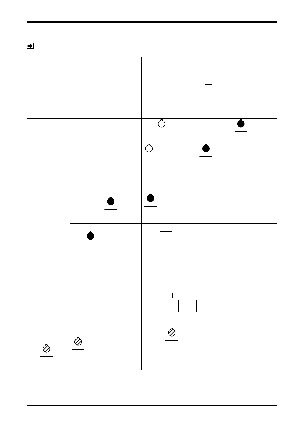
11. TROUBLESHOOTING
RESET
▲
STOP
ROT.
RESET
▲
STOP
ROT.
STOP
ROT.
STOP
ROT.
STOP
ROT.
RESET
▲
START
▲
START
▲
START
▲
NOTE: If troubleshooting below does not work at all, seek our service.
B-320-2-E
SYMPTOM POSSIBLE CAUSE CHECKOUT AND COUNTERMEASURE
Battery pack is not in place.
Remove register front cover to see if the battery pack is
in place.
Check voltage across test pin IN on the display board
of internal assembly and terminal G of the housing.
1. Display is dead.
A weak battery.
(1) Correct level: 2.6V or higher
(2) Low level: 2.5V or lower
(1) indicates a fault suspected in the internal
assembly.
(2) requires battery pack replacement.
Press
button once and then hold the
button depressed for more than 3 sec. If pressing
Not switched in the batch setup
mode. (LCD display does not
button followed by
button depression
blink showing the setup mode.)
fails to switch to the setup mode, repeat the same
procedure with internal buttons on the internal assembly.
If this proves to be successful, a fault is suspected in the
external buttons or in the internal assembly.
A desired batch setpoint is
Following your choice of setpoint, don't forget to press
2. Cannot establish
a batch setpoint.
shown, but the
button
has not been pressed to set it.
than 10 sec. in the course of setting will result in returning
to the previous setting automatically.)
button to set it. (A pause for next operation longer
Can set a batch setpoint but,
upon
button depression,
If in the
setting, shows it for 2 sec. approx. and then "0" in the
mode, the display, following a batch
ADD
standby mode.
the display reading return to "0".
If adjusting a gure or carrying a number to the next
Can not set a desired batch set
point.
column with external buttons is disabled, repeat the same
procedure with internal buttons on the internal assembly.
If this proves to be successful, a fault is suspected in the
external buttons or in the internal assembly.
Open up the register front cover and make sure that
of SW1-2 in the internal assembly is in
button once.
3. Cannot set
parameters.
Not switched in the setup mode.
Cannot set up parameters.
SET⇔RUN
SET
and press
Failure to set up parameters with internal buttons
indicates a fault suspected in the internal assembly.
Ref. page
30
36
29
20
20
20
20
22
22
23
4. Shutoff valve
fails to respond
to
button
depression.
button is not pressed in as
far as it will go.
If pressing
button as far as it will go does not
work, repeat the same procedure with the internal
buttons. If this proves to be successful, a fault is
suspected in the external buttons or in the internal
assembly.
Continued on next page.
⇨
16
37
Page 38
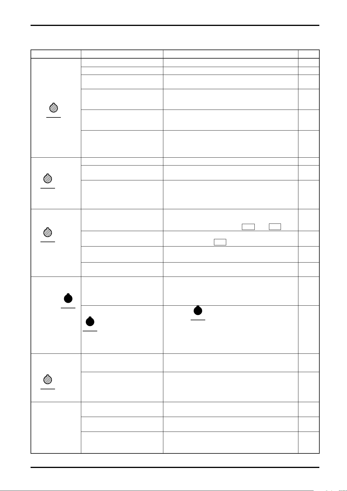
B-320-2-E
START
▲
START
▲
START
▲
STOP
ROT.
STOP
ROT.
STOP
ROT.
START
▲
SYMPTOM POSSIBLE CAUSE CHECKOUT AND COUNTERMEASURE
Batch setpoint at "0". Set to any batch setpoint other than 0. 21
Not reset after a batch operation. Reset each time a batch process has been completed. 21
4. Shutoff valve
fails to respond
to
button
depression.
Shutoff valve operating air
pressure is low, or not supplied.
Air signal line for operating
the shutoff valve is connected
incorrectly.
Trouble lies in the solenoid valve.
(Air output signal from the solenoid
valve fails to be switched.)
Readjust air pressure with reducing valve, etc. 13
Referring to Sec. 5 "Air Signal Line Connections" in this
manual, inspect air signal line connections.
Referring to Sec. 5 "Air Signal Line Connections", make
sure of proper air signal switching and its output.
Trouble lies in the shutoff valve (if
air output signal from the solenoid
valve above has been properly
Isolate problems in the shutoff valve. -
switched).
5. Shutoff valve
responds to
Flowrate is low. Open shutoff valve progressively. -
Pump pressure or head pressure is
low.
Taking pressure loss of the entire piping system into
account, adjust to the proper pump or head pressure.
button
but the process
Oval rotors stuck with solids and
locked, blocking the uid ow.
Referring to Sec. 9.3 "Flowmeter Body Disassembly",
disassemble the meter and inspect it for condition.
uid fails to ow.
6. Shutoff valve
responds to
button
and the process
uid ows, but
the totalizer does
not count.
Trouble lies in the sensor
assembly.
Flowrate signal frequency has
exceeded its limit.
Sensor installed the wrong way.
Oval rotors installed the wrong
way.
Make sure to see if the sensor provides a ow signal
output. Referring to Sec. 9.1 "Register Inspection",
monitor waveshapes at test pins
SIG
Inspect similar to the above and make sure that the pulse
frequency at test pin
is held below 200Hz.
PLS
Referring to Sec. 9.2 "Register Disassembly", inspect
the sensor for correct installation.
Referring to Sec. 9.3 "Flowmeter Body Disassembly",
inspect the meter for correct installation.
Double-acting type shutoff
7. Pressing
valve: Shutoff valve operating air
pressure has decreased during a
batch process.
Readjust air pressure with reducing valve, etc. 12 to 13
and
PLS
Ref. page
13 to 15
13 to 15
-
32 to 35
29
.
29
30
31
32 to 35
button fails to
stop the shutoff
valve.
8. Shutoff valve
does not open
promptly upon
button
depression.
9. Unusual sound
from the
owmeter body.
38
button is not pushed in all
the way.
Time lag is not consistent.
Time lag is consistent.
Air is entrapped.
Process uid vaporizes in the
pipeline.
Oval rotors are revolving in
contact with the measuring
chamber.
If pressing
button all the way does not work,
repeat the same procedure with internal buttons on the
internal assembly. If this proves to be successful, trouble
is suspected in the external buttons or in the internal
assembly.
Any uctuations in shutoff valve operating air pressure?
The compressor has adequate air capacity? Any leaks
at pipeline connections?
Reduce owrate and let the air in the pipeline out
completely.
Reduce owrate and adjust process uid temperature
and pressure until vaporization ceases.
Referring to Sec. 9.3 "Flowmeter Body Disassembly",
disassemble and inspect for condition.
Continued on next page.
⇨
16
19
-
-
-
-
32 to 35
Page 39

B-320-2-E
RESET
▲
RESET
▲
SYMPTOM POSSIBLE CAUSE CHECKOUT AND COUNTERMEASURE
10. Liquid leaks from
the pipeline.
11. Counts while
the shutoff valve
remains closed.
Incomplete seals at pipeline
connections.
Incomplete seal in the rear cover
of owmeter body.
Leaks from shutoff valve or
pipeline connections.
Air pockets exist between the
shutoff valve and owmeter body;
the rotors keep a rocking motion
Retighten bolts at pipeline connections or replace
gaskets.
Inspect owmeter rear cover tting bolts for tightness or
replace O-ring with new one.
Inspect shutoff valve and pipeline connections for leaks. -
Discharge the air to atmosphere. in response to pulsating pump
pressure.
Pulsation of the uid causes
12. Counter reading
too high.
the rotors to move in a rocking
motion.
Inuenced by external magnetic
elds. (The ow sensor picks
up external magnetic elds of a
Provide a check valve and accumulator.
Isolate from external magnetic elds. 11
motor, generator, etc.)
Air entrapped. Discharge the air to atmosphere. -
13. Counter reading
too low.
Inuenced by external magnetic
elds (the ow sensor picks up
external magnetic elds of a
Isolate from external magnetic elds. 11
motor, generator, etc.)
"BATT" alarm
14.
blinks.
"BATT" alarm
15.
blinks and
"ALM" stays on.
16. Batch process
fails to stop
at the target
setpoint.
Indicates a weak battery.
A low battery alarm. (The battery
is generally no longer serviceable
in this state.)
Trouble lies in the internal
assembly.
Trouble lies in the solenoid valve.
Referring to Sec. 10.2 "Battery Pack Replacement",
replace the battery pack early.
The meter is out of service until the battery is replaced.
Referring to Sec. 10.2 "Battery Pack Replacement",
replace with a new one.
Does "OUT" go out and "END" light in the LCD at batch
setpoint? Monitor waveshapes according to Sec. 9.1
"Register Inspection.
Is the output (air signal) from solenoid valve switched
correctly at batch setpoint?
(With LW76E: OUT 1 OFF, OUT 2 OFF)
17. Batch process
stops while
metering is in
progress.
Single-acting shutoff valve:
Shutoff valve operating air
pressure has dropped.
Intermittent interruption of the
process uid ow during a batch
process causes missing pulse
Has the air pressure dropped below the operating
pressure range?
Make sure of process uid ow. 10
detection and shutoff valve
closure signal generation.
Ref. page
-
32 to 35
36
36
17
29
15
-
18. Cannot reset the
alarm.
19. LCD display is
dim.
button is not pushed in as
far as it will go.
The register is located higher
than the operator's eye level.
If pressing the
button fails to reset, repeat the
same procedure with internal buttons in the internal
assembly. If this proves to be successful, trouble lies in
the external buttons or in the internal assembly.
You can best view this LCD from above. Adjust its
installation height for best readability.
16
19
11
39
Page 40
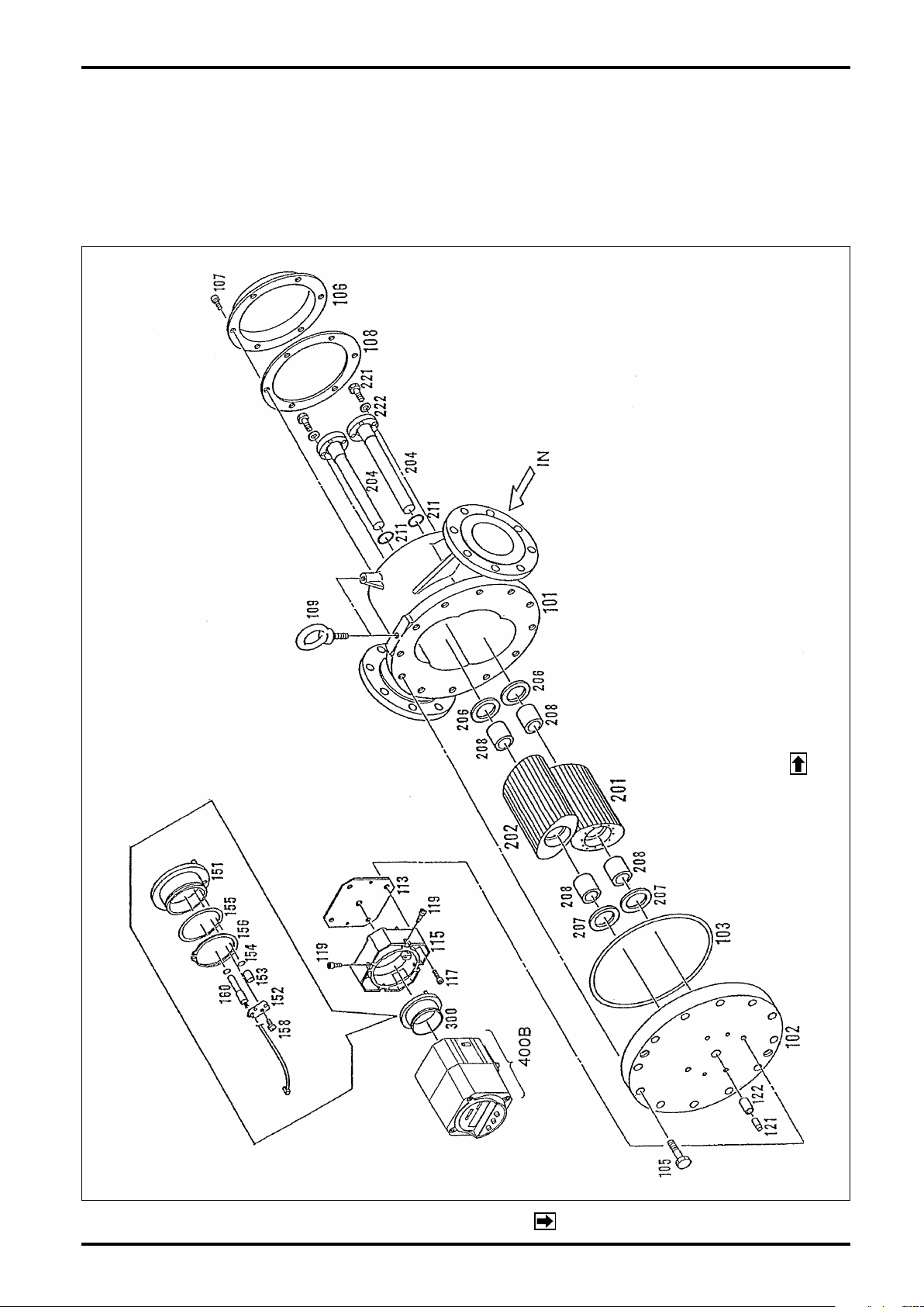
B-320-2-E
12. EXPLODED VIEWS AND PARTS LIST
When you order replacement parts, specify the stock No., flowmeter model, instruction
●
manual No., symbol No., part name and the quantity desired.
12.1 Size 29 Single Case Construction Meter Exploded View and Parts List
12.1.1 Size 29 Single Case Construction Meter Exploded View
(The 1st rotor is below the other.)
NOTE: Flow direction from right to left, viewed from the register
40
NOTE: See next page for parts list.
Page 41

12.1.2 Size 29 Single Case Construction Meter Parts List
B-320-2-E
Symbol No. Part Name Q’ty Remarks
100
101
102
103
▲
105
106 Rear Cover 1
107
108 Rear Cover Gasket 1
109 Eyebolt 2 M10 × 18
113
115
117
119
121
122
200
201
※
202 Second Rotor 1
※
204 Rotor Shaft 2
206 Thrust Ring A 2
207 Thrust Ring B 2
208 Rotor Bearing 4
※
211
221
222
: Rotors and rotor bearings are matched pairs and are
※
available as an assembly.
: Recommended spare parts.
▲
Meter Body Assembly
Meter Body 1
Front Cover 1
O-Ring 1
Front Cover Fitting Bolt
Rear Cover Fitting Bolt
Gasket 1
Adapter 1
Adapter Fitting Bolt 4 M10 × 35
Register Fitting Bolt
Iron Slug 1
Spacer 1
Inner Case Assembly
First Rotor 1
O-Ring 2
Shaft Fitting Bolt 8 M8 × 25
Shaft Fitting Bolt Washer
1 set
12 M16 × 60
6 M8 × 20
4 M6 × 12
1 set
Signal magnet embedded
8 M8
Symbol No. Part Name Q’ty Remarks
300 Sensor Assembly 1 set
151 Sensor Fitting Disc 1
152
153
154
155
156
158
160 Sensor Unit 1
400 B Register Assembly 1 set
Sensor Retainer 1
Blind Plug 1
O-Ring B 2 S10
O-Ring C 1 G65
C-shaped Stop Ring
Cross Recessed Pan Head Screw
(151 to 158, 160)
1
2
M4 × 8 (with washer)
See page
⇨
54.
41
Page 42
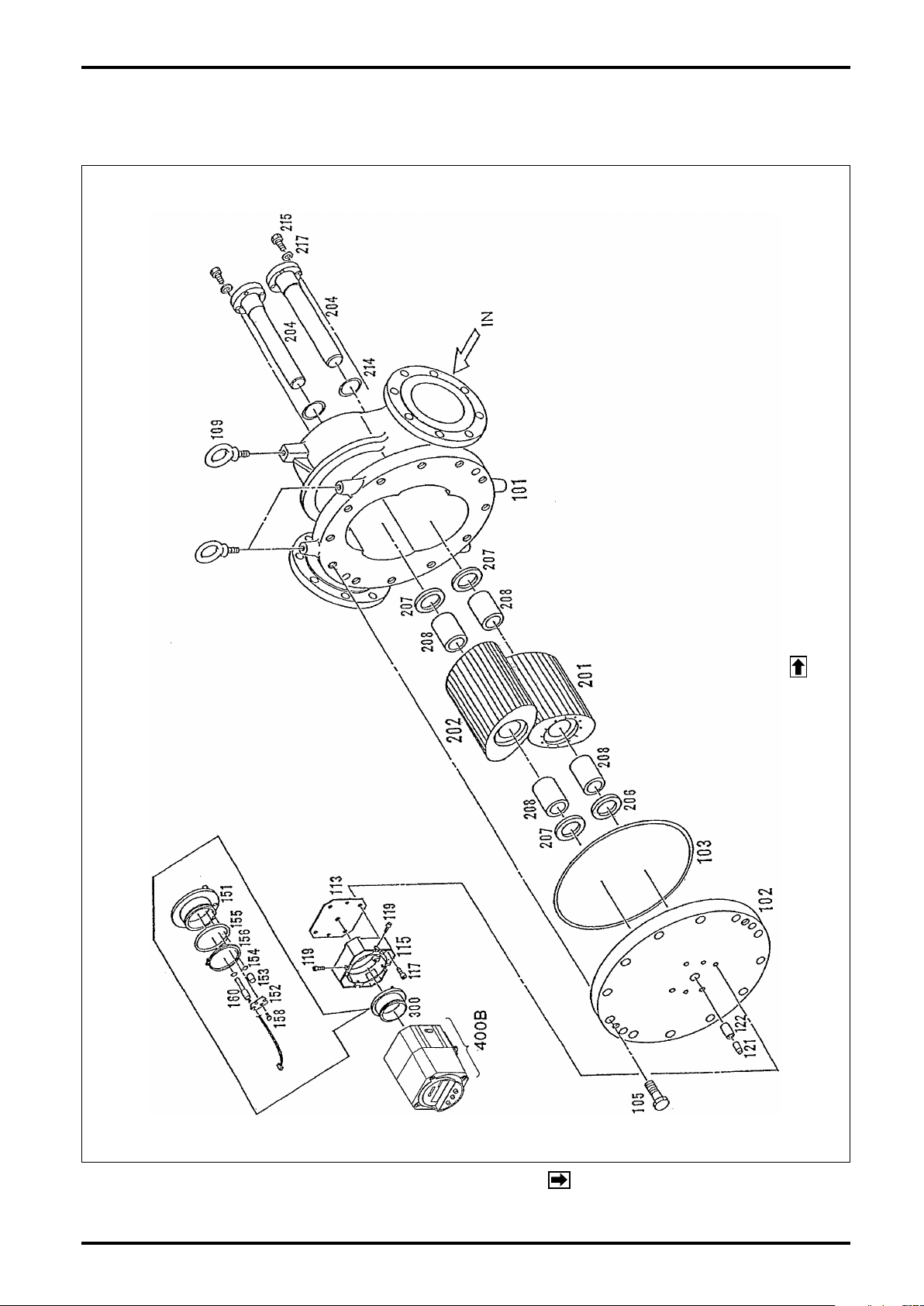
B-320-2-E
12.2 Size 60 Single Construction Meter Exploded View and Parts List
12.2.1 Size 60 Single Construction Meter Exploded View
(The 1st rotor is below the other.)
NOTE: Flow direction from right to left, viewed from the register
42
NOTE: See next page for parts list.
Page 43

12.2.2 Size 60 Single Case Construction Meter Parts List
B-320-2-E
Symbol No. Part Name Q’ty Remarks
100
101
102
103 O-Ring 1 JIS P-320
▲
105
109 Eyebolt 2 M12
113
115
117
119 Register Fitting Bolt 4 M6 × 12
121
122
200
201
※
202 Second Rotor 1
※
204 Rotor Shaft 2
206 Thrust Ring A 1
207 Thrust Ring B 3
208 Rotor Bearing 4
※
214
215
217
: Rotors and rotor bearings are matched pairs and are
※
available as an assembly.
: Recommended spare parts.
▲
Meter Body Assembly
Meter Body 1
Front Cover 1
Front Cover Fitting Bolt
Gasket 1
Adapter 1
Adapter Fitting Bolt 4 M10 × 35
Iron Slug 1
Spacer 1
Inner Case Assembly
First Rotor 1
O-Ring 2 JIS S-42
Shaft Fitting Bolt 8 M10 × 35
Shaft Fitting Bolt Washer
1 set
12 M16 × 60
1 set
Signal magnet embedded
8 M10
Symbol No. Part Name Q’ty Remarks
300 Sensor Assembly 1 set
151 Sensor Fitting Disc 1
152
153
154
155
156
158
160 Sensor Unit 1
400 B Register Assembly 1 set⇨See page 54.
Sensor Retainer 1
Blind Plug 1
O-Ring B 2 S10
O-Ring C 1 G65
C-shaped Stop Ring
Cross Recessed Pan Head Screw
(151 to 158, 160)
1
2
M4 × 8 (with washer)
43
Page 44
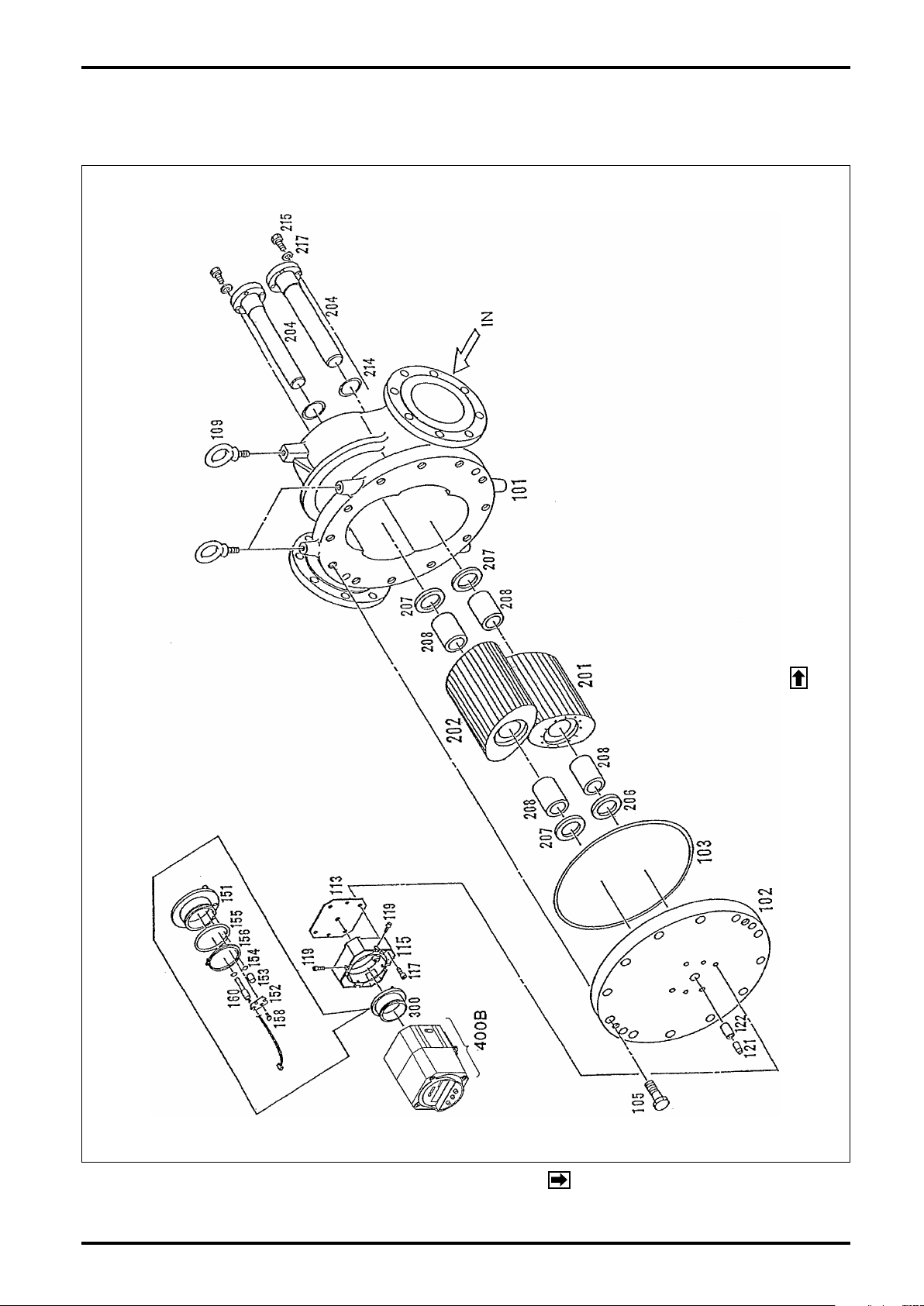
B-320-2-E
12.3 Size 31 Single Case Construction Meter Exploded View and Parts List
12.3.1 Size 31 Single Case Construction Meter Exploded View
(The 1st rotor is below the other.)
NOTE: Flow direction from right to left, viewed from the register
44
NOTE: See next page for parts list.
Page 45

12.3.2 Size 31 Single Case Construction Meter Parts List
B-320-2-E
Symbol No. Part Name Q’ty Remarks
100
101
102
103
▲
105
109 Eyebolt 2 M12
113
115
117
119 Register Fitting Bolt 4 M6 × 12
121
122
200
201
※
202 Second Rotor 1
※
204 Rotor Shaft 2
206 Thrust Ring 4
208 Rotor Bearing 4
※
214
215
217
Meter Body Assembly
Meter Body 1
Front Cover 1
O-Ring 1 JIS P-400
Front Cover Fitting Bolt
Gasket 1
Adapter 1
Adapter Fitting Bolt 4 M10 × 35
Iron Slug 1
Spacer 1
Inner Case Assembly
First Rotor 1
Keystone Ring 2
Blind Cover 2
Blind Cover Fitting Bolt
1 set
12 M24 × 75
1 set
Signal magnet embedded
8 M10 × 35
Symbol No. Part Name Q’ty Remarks
300 Sensor Assembly 1 set
151 Sensor Fitting Disc 1
152
153
154
155
156
158
160 Sensor Unit 1
400 B Register Assembly 1 set⇨See page 54.
Sensor Retainer 1
Blind Plug 1
O-Ring B 2 S10
O-Ring C 1 G65
C-shaped Stop Ring
Cross Recessed Pan Head Screw
(151 to 158, 160)
1
2
M4 × 8 (with washer)
: Rotors and rotor bearings are matched pairs and are
※
available as an assembly.
: Recommended spare parts.
▲
45
Page 46
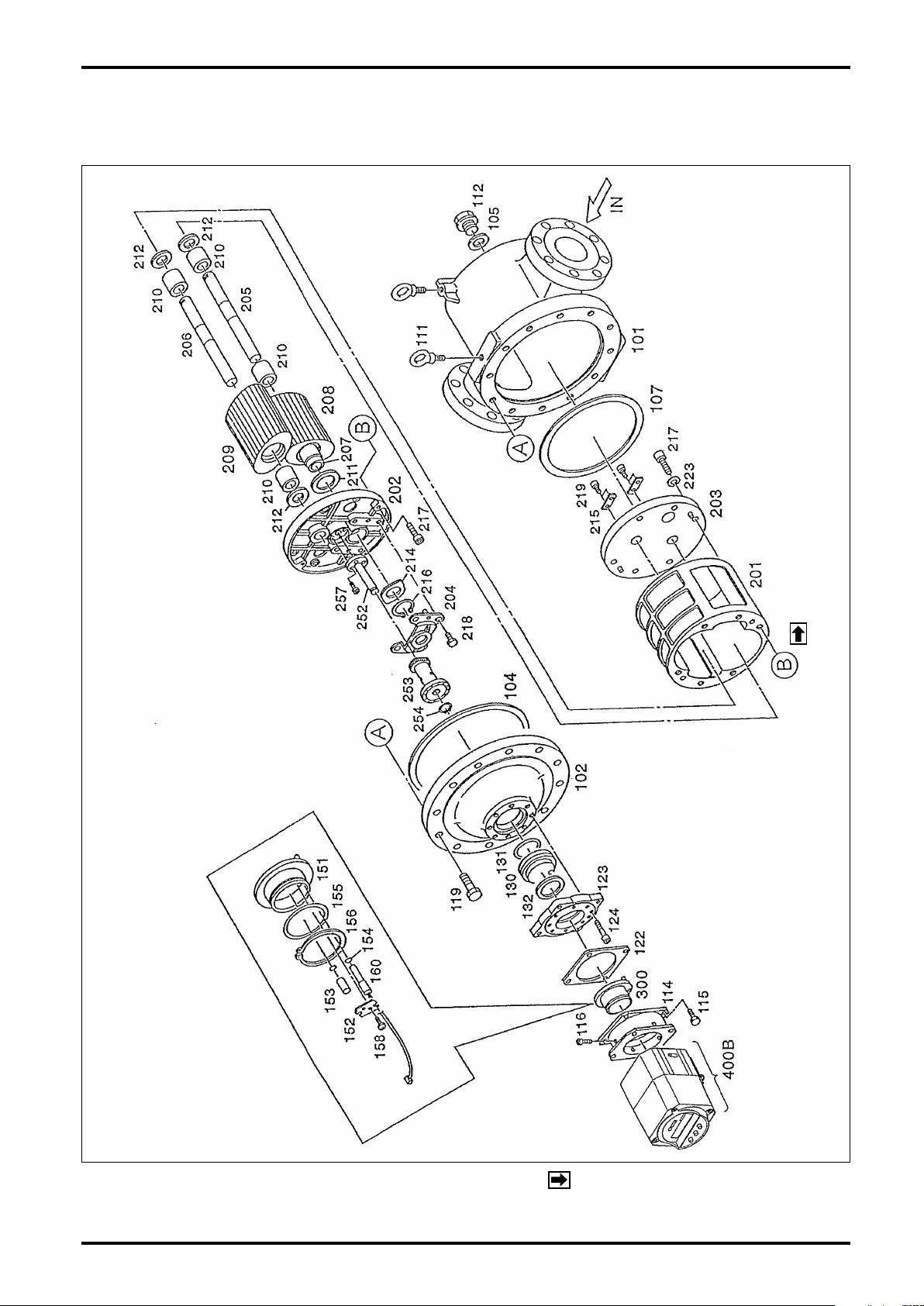
B-320-2-E
12.4
Sizes 28, 29, and 31 Double Case Construction Meter, 10K type Exploded View and Parts List
12.4.1 Sizes 28, 29, and 31 Double Case Construction Meter, 10K type Exploded View
(The 1st rotor is below the other.)
NOTE: Flow direction from right to left, viewed from the register
46
NOTE: See next page for parts list.
Page 47

B-320-2-E
12.4.2 Sizes 28, 29, and 31 Double Case Construction Meter, 10K Type Parts List
Symbol No. Part Name
100
101
102
104
▲
105
107
111 Eyebolt 2 M10 1 M10 1 M10
112 Blind Plug 1 1 1 G1
114
115 Adapter Fitting Bolt 4 M10 × 20 4 M10 × 20 4 M10 × 20
116 Register Fitting Bolt 4 M6 × 12 4 M6 × 12 4 M6 × 12
119
122 Gasket 1 1 1
123
124
130 Sealing Plate 1 1 1
131
▲
132 Sealing Plate Gasket 1 1 1
200 Inner Case Assembly 1 set 1 set 1 set
201
202 Inner Case Top Cover 1 1 1
203 inner Case Bottom Cover 1 1 1
204 Longer Shaft Holder 1 1 1
205 First Rotor Shaft 1 1 1
206 Second Rotor Shaft 1 1 1
207 Uniform-motion Gear Boss 1 1 1
208 First Rotor 1 1 2
※
209 Second Rotor 1 1 - ---
※
210
※
211 Thrust Ring A 1 1 1
212
214
215 Shaft Non-turn Strip 2 2 2
216 Stop Ring 1 1 1
217
218
219
223 Spring Washer 6 M12 6 M12 6 M12
252 Signal Magnet Shaft 1 1 1
253
254 Stop Ring 1 C14 1 C14 1 C14
257
300 Sensor Assembly 1 set (151 to 158, 160)
151 Sensor Fitting Bracket 1
152
153 Blind Plug 1
154
155
156 C-shaped Stop Ring 1
158
160 Sensor Unit 1
400 B Register Assembly 1 set⇨See page 54
: Rotors and rotor bearings are matched pairs and are available as an assembly.
※
: Recommended spare parts.
▲
Outer Case Assembly
Outer Case 1 1 1
Front Cover 1 1 1
Gasket, Outer Case Top Cover 1 1 1
Blind Hole Gasket 1 1 1
Gasket, Inner Case Bottom Cover
Adapter 1 1 1
Outer Case Top Cover Fitting Bolt
Sealing Flange 1 1 1
Hex Socket Head Bolt 8 M10 × 45 8 M10 × 45 8 M10 × 45
O-Ring 1 1 1
Inner Case 1 1 1
Rotor Bearing 4 4 4
Thrust Ring B 3 3 3
Uniform-motion Drive Gear 1 1 1
Inner Case Top/Bottom Cover Fitting Bolt
Longer Shaft Holder Fitting Bolt
Shaft Non-turn Strip Fitting Screw
Signal Generating Magnet Assembly
Signal Magnet Shaft Fitting Bolt
Sensor Retainer 1
O-Ring B 2 S10
O-Ring C 1 G65
Cross Recessed Pan Head Screw
Q'ty Remarks Q'ty Remarks Q'ty Remarks
1 set 1 set 1 set
12 M16 × 65 12 M16 × 65 16 M16 × 60
12 M12 × 35 12 M12 × 35 12 M12 × 35
1 set 1 set 1 set
Size 28 Size 29 Size 31
1 1 1
4 4 4 M10 × 25
4 4 4
4 M5 4 M5 4 M5
2 M4 × 8 (with washer)
47
Page 48
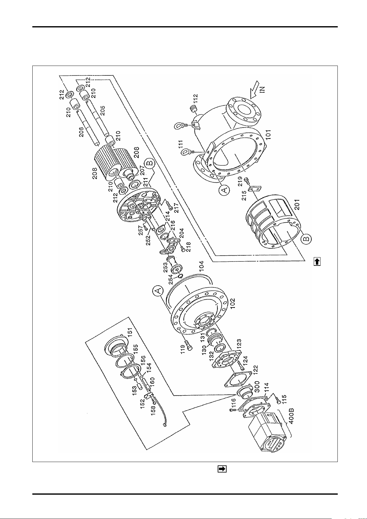
B-320-2-E
12.5 Size 60 Double Case Construction Meter, 10K type Exploded View and Parts List
12.5.1 Size 60 Double Case Construction Meter, 10K type Exploded View
(The 1st rotor is below the other.)
NOTE: Flow direction from right to left, viewed from the register
48
NOTE: See next page for parts list.
Page 49

12.5.2 Size 60 Double Case Construction Meter, 10K Type Parts List
B-320-2-E
Symbol No. Part Name Q’ty Remarks
100
101
102
104
▲
111 Eyebolt 2
112
114
115
116 Register Fitting Bolt 4 M6 × 12
119
122
123
124
130
131
▲
132
200
201
202 End Plate 1
204 Major Axis Holder 1
205 First Rotor Shaft 1
206 Second Rotor Shaft 1
207
208 Rotor 2
※
210
※
211
212
214
215
216 Stop Ring 1 C42
217
218
219
252
253
254 Stop Ring 1
257
: Rotors and rotor bearings are matched pairs and are
※
available as an assembly.
: Recommended spare parts.
▲
Outer Case Assembly
Outer Case 1
Front Cover 1
Gasket 1
Blind Plug 2 R1
Adapter 1
Adapter Fitting Bolt 4 M10 × 20
Front Cover Fitting Bolt
Gasket 1
Sealing Flange 1
Hex Socket Head Bolt
Sealing Plate 1
O-Ring 1
Sealing Plate Gasket
Inner Case Assembly
Inner Case 1
Uniform-motion Gear Boss
Rotor Bearing 4
Thrust Ring A 1
Thrust Ring B 3
Uniform-motion Drive Gear
Shaft Non-turn Strip
End Plate Fitting Bolt
Major Axis Holder Fitting Bolt
Shaft Non-turn Strip Fitting Screw
Signal Magnet Shaft
Signal Generating Magnet Assembly
Signal Magnet Shaft Fitting Bolt
1 set
16 M16 × 65
8 M10
1
1 set
1
1
1
4 M12 × 45
4 M10 × 20
2 M10 × 15
1
1 set
4 M5
Symbol No. Part Name Q’ty Remarks
300 Sensor Assembly 1 set
151
152
153
154
155
156
158
160 Sensor Unit 1
400 B Register Assembly 1 set⇨See page 54.
Sensor Fitting Bracket
Sensor Retainer 1
Blind Plug 1
O-Ring B 2 S10
O-Ring C 1 G65
C-shaped Stop Ring
Cross Recessed Pan Head Screw
(151 to 158, 160)
1
1
2
M4 × 8 (with washer)
49
Page 50
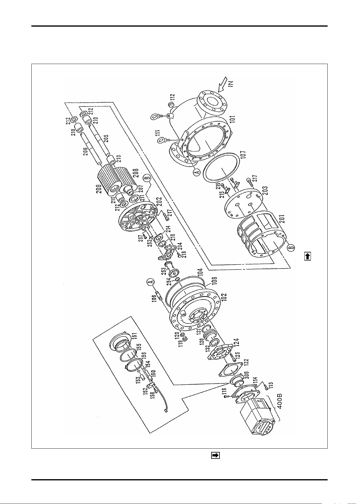
B-320-2-E
12.6
Sizes 28, 29, and 31 Double Case Construction Meter, 30K type (F3) Exploded View and Parts List
12.6.1 Sizes 28, 29, and 31 Double Case Construction Meter, 30K type (F3) Exploded View
(The 1st rotor is below the other.)
NOTE: Flow direction from right to left, viewed from the register
50
NOTE: See next page for parts list.
Page 51

B-320-2-E
12.6.2 Sizes 28, 29, and 31 Double Case Construction Meter, 30K Type (F3) Parts List
Symbol No. Part Name Q’ty Remarks
Outer Case Assembly
Outer Case
Front Cover
O-Ring
Stud Bolt
Gasket, Inner Case Bottom
Gasket, Inner Case Top
Eyebolt
Blind Plug
Adapter
Adapter Fitting Bolt
Register Fitting Bolt
Nut
Washer
Gasket
Sealing Flange
Hex Socket Head Bolt
Sealing Plate
O-Ring
Sealing Plate Gasket
1 set
16
16
16
1
1
1
1
1
2
2 R1
1
4
4 M6
1
1
8 M10
1
1
1
▲
▲
100
101
102
104
106
107
108
111
112
114
115
116
119
120
122
124
125
130
131
132
Symbol No. Part Name Q’ty Remarks
300 Sensor Assembly
151
152 Sensor Retainer
153 Blind Plug
154 O-Ring B
155
156
158
160 Sensor Unit
400
Sensor Fitting Bracket
O-Ring C
C-shaped Stop Ring
Cross Recessed Pan Head Screw
Register Assembly
B
1 set
1 set
(151 to 158, 160)
1
1
1
S10
2
G65
1
1
M4 × 8 (with washer)
2
1
See page 54.
⇨
※
※
※
200
201
202
203
204
205
206
207
208
209
210
211
212
214
215
216
217
218
219
252
253
254
257
Inner Case Assembly
Inner Case
Inner Case Top Cover
Inner Case Bottom Cover
Longer Shaft Holder
First Rotor Shaft
Second Rotor Shaft
Uniform-motion Gear Boss
First Rotor
Second Rotor
Rotor Bearing
Thrust Ring A
Thrust Ring B
Uniform-motion Drive Gear
Shaft Non-turn Strip
Stop Ring
Inner Case Top/Bottom Cover Fitting Bolt
Longer Shaft Holder Fitting Bolt
Shaft Non-turn Strip Fitting Screw
Signal Magnet Shaft
Signal Generating Magnet Assembly
Stop Ring
Signal Magnet Shaft Fitting Bolt
1 set
1
1
1
1
1
1
1
1
1
4
1
3
1
2
1 C35
12
4
4 M4
1
1 set
1
4 M5
: Rotors and rotor bearings are matched pairs and are
※
available as an assembly.
: Recommended spare parts.
▲
51
Page 52
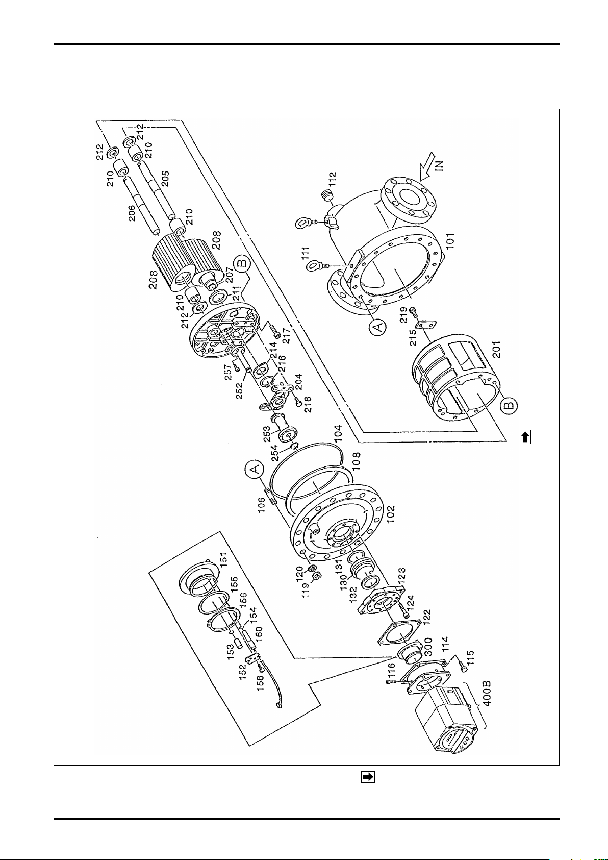
B-320-2-E
12.7 Size 60 Double Case Construction Meter, 30K type (F3) Exploded View and Parts List
12.7.1 Size 60 Double Case Construction Meter, 30K type (F3) Exploded View
(The 1st rotor is below the other.)
NOTE: Flow direction from right to left, viewed from the register
52
NOTE: See next page for parts list.
Page 53

12.7.2 Size 60 Double Case Construction Meter, 30K Type (F3) Parts List
B-320-2-E
Symbol No. Part Name Q’ty Remarks
100
101
102
104
▲
106 Stud Bolt 16 M20 × 95
108
111 Eyebolt 2 M12 × 22
112
114
115
116 Register Fitting Bolt 4 M6 × 12
119 Nut 16 M20
120
122
123
124
130
131
▲
132
Outer Case Assembly
Outer Case 1
Front Cover 1
O-Ring 1 P320
Gasket, Inner Case Bottom
Blind Plug 2 R1
Adapter 1
Adapter Fitting Bolt 4 M10 × 20
Washer 16 M20
Gasket 1
Sealing Flange 1
Hex Socket Head Bolt
Sealing Plate 1
O-Ring 1
Sealing Plate Gasket
1 set
1
8 M10
1
Symbol No. Part Name Q’ty Remarks
300 Sensor Assembly
151
152 Sensor Retainer
153 Blind Plug
154 O-Ring B
155
156
158
160 Sensor Unit
400 B Register Assembly
Sensor Fitting Bracket
O-Ring C
C-shaped Stop Ring
Cross Recessed Pan Head Screw
1 set
1 set
(151 to 158, 160)
1
1
1
S10
2
G65
1
1
M4 × 8 (with washer)
2
1
See page 54.
⇨
200
201
202
204
205
206 First Rotor Shaft 1
207 Second Rotor Shaft 1
208
※
210 First Rotor 4
※
211
212
214
215
216
217
218 Stop Ring 4 M10 × 20
219
252
253
254 Stop Ring 1
257
: Rotors and rotor bearings are matched pairs and are
※
available as an assembly.
: Recommended spare parts.
▲
Inner Case Assembly
Inner Case 1
Inner Case Top Cover
Inner Case Bottom Cover
Longer Shaft Holder
Uniform-motion Gear Boss
Second Rotor 1
Rotor Bearing 3
Thrust Ring A 1
Thrust Ring B 1
Uniform-motion Drive Gear
Shaft Non-turn Strip
Inner Case Top/Bottom Cover Fitting Bolt
Longer Shaft Holder Fitting Bolt
Shaft Non-turn Strip Fitting Screw
Inner Case Top/Bottom Cover Fitting Bolt
1 set
1
1
1
2
1 C42
4 M12 × 45
2 M10 × 15
1
1 set
4 M5
53
Page 54
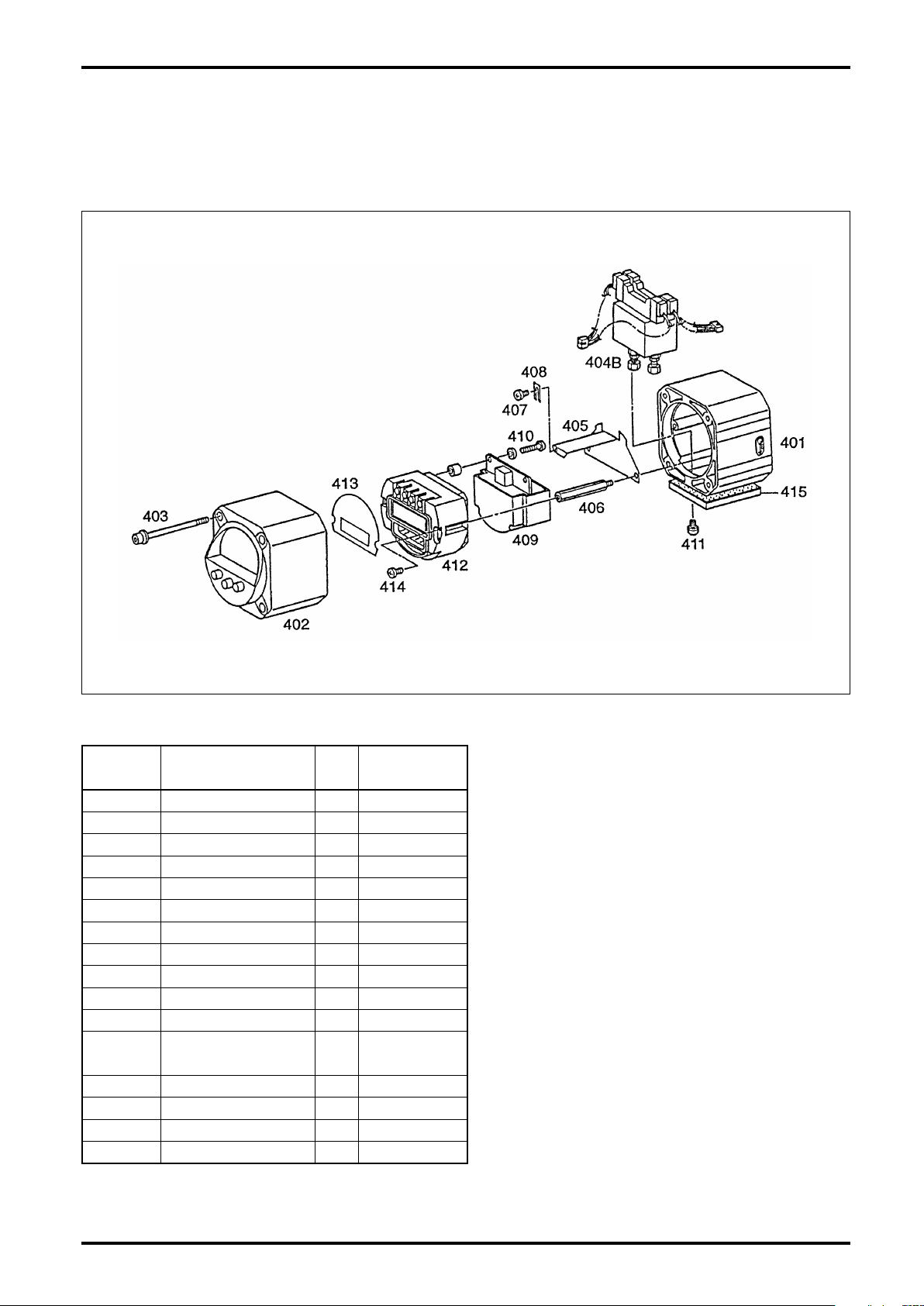
B-320-2-E
12.8 Register Exploded View and Parts List
When you order replacement parts, specify the stock No., flowmeter model, instruction
●
manual No., symbol No., part name and the quantity desired.
EXPLODED VIEW
◇
◇
PARTS LIST
◇
Symbol
No.
400 B
401
402 Register Front Cover 1
403
404 B
405 Retainer 1
406 Hex Strut 2 M4
407 Retaining Setscrew 1
408 Hold-down Strip 1
409 Battery Pack 1
▲
410
411
412
413
414
415 Hold-down Base 1 with packing
: Recommended spare parts.
▲
◇
Part Name Q'ty Remarks
LW74E Register Assembly
Register Body 1
Fitting Bolt, Front Cover
Solenoid Valve Assembly
Battery Pack Fitting Screw
Solenoid Valve Fitting
Bolt
Internal Assembly 1
Faceplate 1
Internal Ass’y Fitting Screw
1 set (401 to 415)
with pushbuttons
4
M6 with washer
1
for LW76E register
5 M3
M4 with
8
washer
2
M4 with washer
54
Page 55

13. GENERAL SPECIFICATIONS
Register Assembly
●
B-320-2-E
ITEM
Type of control
Signal air pressure
Circuit
Air signal line connection Rc 1/8 with a bite-type tting for φ6 × φ4 copper tubing provided
Pneumatic
Distance to the shutoff valve 3 meters max.
Batch
setpoint or
accumulated
total readout
(selectable
with front
pushbuttons)
Display
Operation status indicators
Low battery alarm Front-panel LCD "BATT" lights up when the battery life has approached.
Type of operation Select either add or subtract mode (subtract mode is standard).
Operation and programming
Initial setting (oP) and
nal setting (cL)
Setup
Missing pulse setting (PL)
Overshoot setup (oV)
Scaler setup
Repeat feature Provided
Emergency stop By front pushbutton (STOP). Can resume measurement for the remaining cycle.
Backup feature Retains parameters, batch setpoint, total reading, cumulative total in an EEPROM.
Power source Dedicated battery (4 years approx., though, depending on operating conditions.)
Waterproof construction JIS C 0920 weatherproof (IP65)
Explosionproof construction
Ambient Temperature Range
External nish Munsell 2.5PB 5/8 (nished in baked melamine)
Enclosure material Aluminum die casting
Physical orientation Horizontal or vertical (view angle is adjustable)
Option Air set (one set) includes a mist separator, combination lter/reducing valve, etc.
Batch setpoint
Accum. total 8-digit, 7-segment LCD (characters 12.7mm high)
Counting unit
Coefcient (F) Set to any point from 0.0001 to 1.9999 in the SET mode
Frequency divide (d)
6-digit, 7-segment LCD except for the 1st and 8th digit
Shows in the 1st and 8th digit of the LCD only in the batch setpoint readout.
STOP, RESET, START manually with three front-panel pushbuttons.
Select one of the following two:
(1) Nonexplosionproof
(2) Intrinsically safe explosionproof: Exia Il BT3
(One-step open mode available by setting the initial value at 0.)
0.20 to 0.69MPa (depends on the shutoff valve rating.)
Meter Size Standard Option
28 ×0.1L × 1L, ×10L
29 ×1L ×10L
60, 31 ×1L ×10L, ×100L
RUN: Blinks while in operation
OUT: Lights up while valve operating signal is being output
ALM: Lights to indicate missing pulses, or exceeding a preset overshoot, etc.
COUNT: Lights up while the totalizer counts
END: Lights up upon completion of a batch cycle
Batch setpoint (6 digits) - Can be changed in the RUN mode.
Cumulative total reading (8 digits) - Can be changed In the SET mode
Set to any point from 0 to 999 counts in the SET mode.
(A setpoint at 0 makes the one-step open, one-step close mode.)
Set to any point from 0 to 15 sec. in the SET mode.
(A setpoint at 0 disables the missing pulse setting.)
Set to any point from 0 to 99 counts in the SET mode.
Selectable from one of 1/1, 1/10, and 1/100 in the SET mode
1) TIIS Explosionproof (Battery powered)
2) NEPSI Explosionproof (Battery powered)
(Valve actuating uid must not contain drain or mist at low temperatures.)
Air two-step open, two-step close
(A setpoint at 0 disables the overshoot setting.)
DESCRIPTION
LW76E
(Air must be clean and dry.)
-10 to +60°C
Nominal Meter Factors
●
NOTE: At standard temp.
Size Number of Pulses, P/r Nominal Meter Factor, L/P Cycle Sample Number
28 12 0.13516
29 12 0.19863
60 12 0.3389
31 12
0.6295
24
55
Page 56

B-320-2-E
NOTE: For outline dimensions and pipeline connection dimensions, see the
approval drawing (or specifications of the product).
All specifications are subject to change without notice for improvement.
2013.03 Revised
2010.02 Revised
B-320-3-E (2)
△
 Loading...