

Page 1
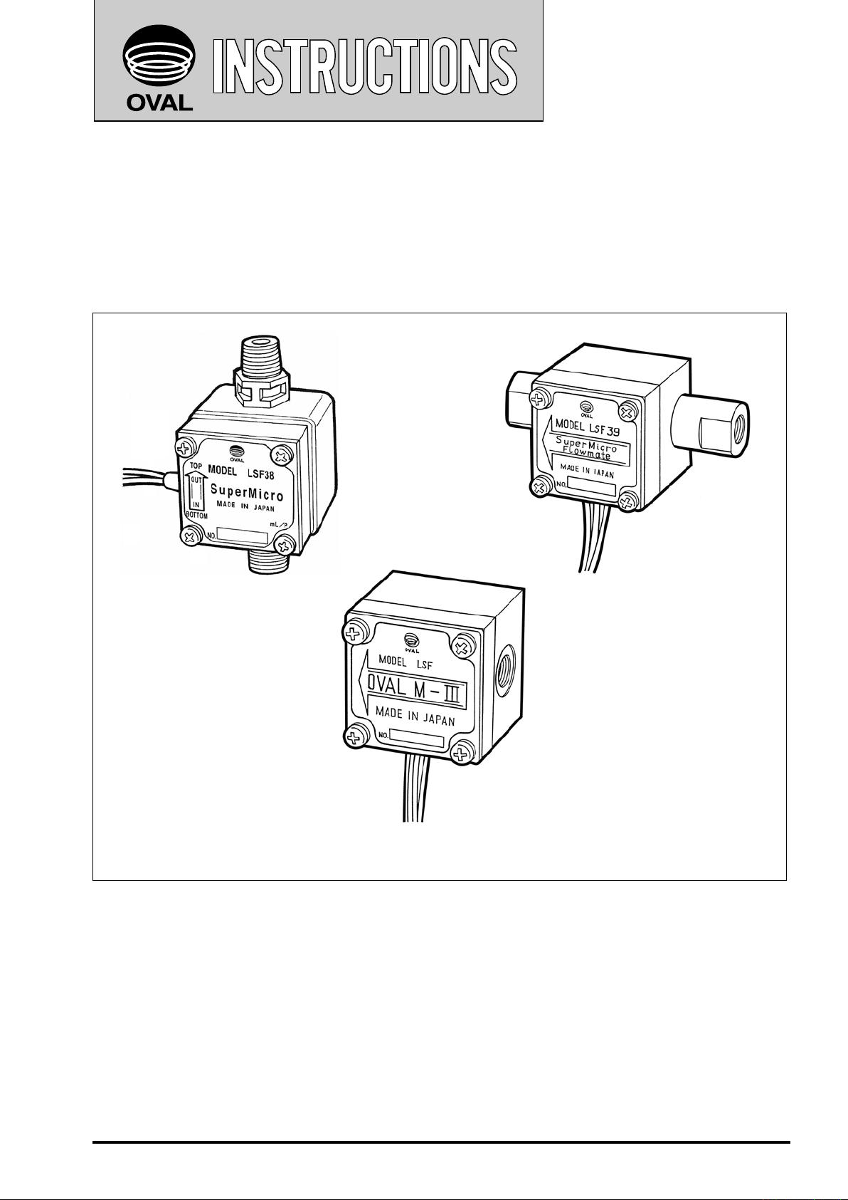
Super Micro Flow Mate
FLOW MATE (OVAL M-
Ins. No. S-176-9-E
)
Ⅲ
MODEL LSF
38
39
40
□□-□□
4
1
45
Super Micro 38
Meter Sizes 40, 4
Every OVAL product is manufactured and functionally tested under stringent quality control before
shipment. In order to maintain its design performance throughout its life, this manual offers the
operator the necessary installation, operation and maintenance information. Be well familiar with
these instructions before you place your meter in service and retain it at the eld location for ready
reference.
1, and 45
Super Micro 39
Fittings provided (option)
1
Page 2
S-176-9-E
CONTENTS
1. BEFORE YOU BEGIN .................................................................................................................................... 3
1.1 Transit Considerations ............................................................................................................................... 3
1.2 Storage Considerations ............................................................................................................................. 3
1.3 Structural Consideration ............................................................................................................................ 3
2. OPERATING CONDITIONS ........................................................................................................................... 4
3. INSTALLATION .............................................................................................................................................. 4
3.1 Tubing Consideration ................................................................................................................................ 4
4. WIRING .......................................................................................................................................................... 5
4.1 Field Wiring ............................................................................................................................................... 5
4.2 Electrical Connections ............................................................................................................................... 5
5. OPERATING INSTRUCTIONS ....................................................................................................................... 6
5.1 Operation ................................................................................................................................................... 6
5.2 Operating Precautions ............................................................................................................................... 7
5.3 Precautions at Operation Shutdown .......................................................................................................... 8
6. DISASSEMBLY AND INSPECTION ............................................................................................................... 9
6.1 Meter Body Disassembly and Inspection .................................................................................................. 9
6.2 Meter Body Assembly .............................................................................................................................. 10
7. TROUBLESHOOTING ..................................................................................................................................11
8. EXPLODED VIEWS AND PARTS LIST ........................................................................................................ 12
8.1 Meter Size 38 .......................................................................................................................................... 12
8.2 Meter Size 39 .......................................................................................................................................... 13
8.3 Meter Sizes 40, 41 and 45 ...................................................................................................................... 14
9. GENERAL SPECIFICATIONS ...................................................................................................................... 15
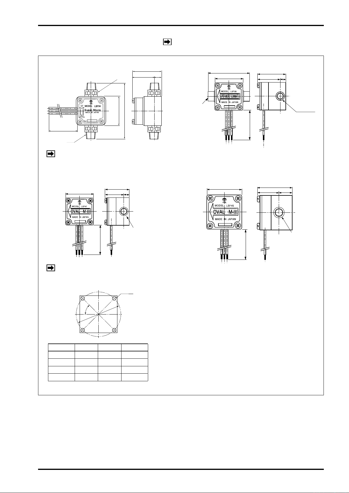
10. OUTLINE DIMENSIONS .............................................................................................................................. 17
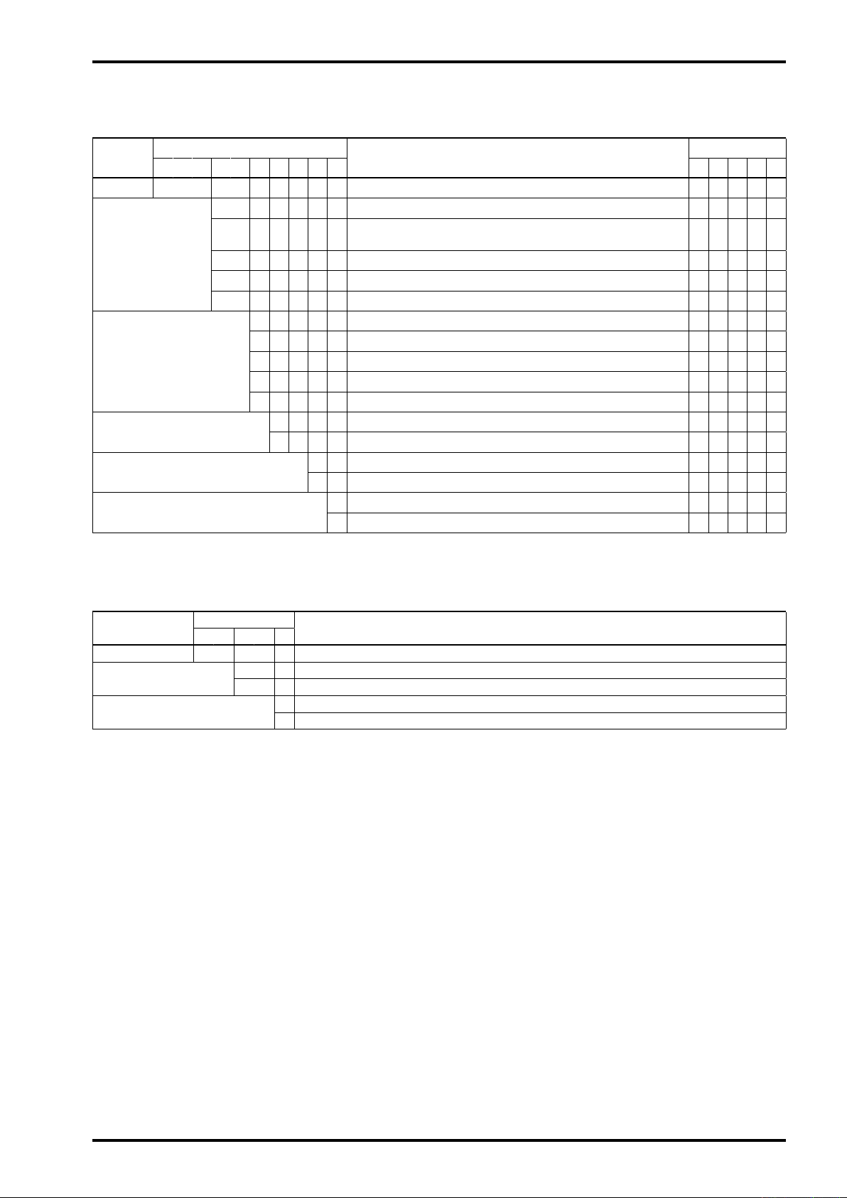
11. PRODUCT CODE EXPLANATION ............................................................................................................... 19
CONVENTIONS
Shown in this manual are the signal words NOTE, CAUTION and WARNING, as described
in the examples below:
2
NOTE: Notes are separated from the general text to bring the user's attention to
important information.
CAUTION: Caution statements signal the user about hazards or unsafe practices
which could result in minor personal injury or product or property
damage.
WARNING: Warning statements signal the user about hazards or unsafe
practices which could result in severe personal injury or death.
Page 3

S-176-9-E
1.BEFORE YOU BEGIN
Every meter is thoroughly tested before it leaves the factory. When received, it should be thoroughly
inspected for any indication of damage during transit.
Necessary handling precautions are described in this section; read the instructions carefully. As for
other information, refer to the respective section. For any inquiries, contact your nearest OVAL sales
ofce.
CAUTION
When you make inquiries, include the product name, model code, serial number, ratings
and other pertinent information.
1.1 Transit Consideration
(1) To safeguard against damage during transit, transport FLOW MATE (OVAL M-Ⅲ) to the installation
site in the original cardboard container used for shipment from the factory if circumstances
permit.
FLOW MATE (OVAL M-Ⅲ) is adjusted and inspected completely with all the components of the meter-
(2)
sensor unit, pulse generator, etc. For this reason, treat them as one complete assembly.
1.2 Storage Considerations
If the meter is going to be stored for long periods of time upon receipt before installation, it could be
damaged or deteriorated due to unforeseen circumstances. If a lengthy storage is expected, the
following precautions should be taken:
Keep FLOW MATE (OVAL M-Ⅲ) in store in the same container used for shipment from OVAL if possible.
(1)
Place of storage should conform to the following requirements:
(2)
Free from rainwater.
★
Free from vibration and impact shocks.
★
Temperature and relative humidity in the storage place are at or near room temperature and
★
humidity (around 25℃ and 65% RH).
(3) If FLOW MATE (OVAL M-Ⅲ) that has once been placed in service is to be stored, it should be purged
2
ith clean air, N
w
inner walls, housing exterior and other components.
NOTE: Use clean detergent, etc. to remove contaminants if necessary.
spin too fast during the ushing or cleansing process.
CAUTION
(4)
The Super Micro 38 has a plastic resin molded joint ; therefore, excessive tightening
or repetition of mounting and dismounting more than necessary may result in broken
joint or loss of airtightness due to deformed taper screw.
(5) If you want to store the meter for extended periods of time, keep it stored under the conditions
similar to those during shipment.
gas, etc. to remove residual process uid from the meter interior, ttings, tubing
Do not allow the meter to
1.3 Structural Consideration
FLOW MATE (OVAL M-Ⅲ) is intended for indoor use. Do not expose it to rainwater or running water.
3
Page 4
S-176-9-E
Bypass Loop
Strainer
Valve
Short Pipe
Flow Direction
2. OPERATING CONDITIONS
To maintain the stated high accuracy and long service life of FLOW MATE (OVAL M-Ⅲ), make sure
that the flowrate, pressure, temperature and viscosity are held within the ratings. The operating
conditions appear in the GENERAL SPECIFICATIONS on page 15. Conrm these ratings before
commencing operation.
CAUTION
If the body material of FLOW MATE (OVAL M -Ⅲ) is aluminum + anodized aluminum coating,
it is not serviceable for water and corrosive liquids.
3. INSTALLATION
3.1 Tubing Considerations
(1)The tubing assembly must be thoroughly flushed. Flushing must be performed before meter
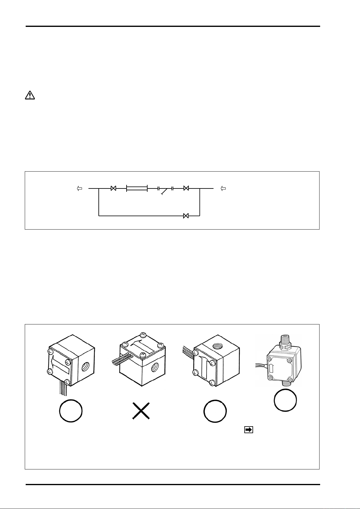
installation. Couple a short pipe section in place of the meter (see the ushing set-up given below).
(2)The meter should be installed exercising due care to avoid pipe strains.
(3)When screwing in the ttings, be very careful not to allow metal chips and seal tape protrusions to
get into the meter
.
(4)The meter should be located downstream of the pump.
(5)Flow direction must conform to the arrow mark indicated on the meter body.
(6)The strainer should be located upstream of, and as close to the meter as possible.
(7)The physical orientation of the meter should be such that its nameplate is vertical as shown below.
(8)When installing Size 38 meter in the tubing assembly, screwing torque at the tting should be
held with in
10N・m.
Measures flow in either
※
direction (from left to right
or from right to left).
4
Avoid meter orientation
※
with nameplate top or
bottom.
Measures ow in either
※
irection (from top to
d
bottom or from top to
bottom).
NOTE: Making measurement with Size 38 meter
is acceptable only in this
orientation (ow direction
from bottom to top).
Page 5
S-176-9-E
200mm approx.
4. WIRING
NOTE : Also see the topic "WIRING" in the instruction
manual of the receiving instrument used.
4.1 Field Wiring
(1)Cables for eld wiring
The following cables should be used unless otherwise specied.
Shielded chloroprene cabtyre cables (kind 2, JIS C 3327, shielded) or shielded vinyl cabtyre
2
cables (JIS C 3312, shielded) with a conductor area 1.25mm
3-conductor cables may be used to suit your specic application. Shielded end should be grounded
t the ground terminal of the receiving instrument.
a
(2)Transmission length
With transmission cables conforming to JIS C 3327 or C 3312 conductor area 1.25mm
maximum transmission length is typically one kilometer.
If
NOTE:
it exceeds one kilometer, consult factory.
(3)Prevention of inductive interference
T
o minimize the possibility of stray current pickup, route the eld wiring sufciently away from other
power cables and power circuits.
.
2
, the
CAUTION: Verify the validity of flowmeter (pulse generator) to receiving instrument
combination by their product No., instrument No., etc. before making wiring
connections.
4.2 Electrical Connections
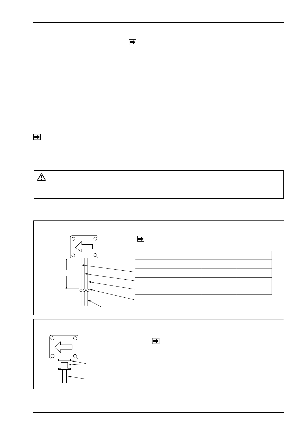
3-Wire System (MR sensor): Meter sizes 38, 39, 40, 4
◆
NOTE ※: Unfactored pulses only with Meter sizes
38 and 39 .
Unfactored pulse
All models
WHT: SIG GRN: SIG YEL: SIG GRN: SIG
Soldered or coupled with connector.
Wire leads (customer to furnish)
-Wire System (reed switch): Meter sizes 40, 4
2
◆
RED: +V RED: +V RED: +V RED: +V
BLK: 0V BLK: 0V BLK: 0V BLK: 0V
※
1, and 45 (unfactored pulses only)
1, and 45
Factored pulse
Size 40 (1mL/p) Size 41 (1mL/p) Size 45 (10mL/p)
Connector and Receptacle
Wire leads (customer to furnish)
NOTE: 1. Remove connector terminals and crimp
wire leads for installation.
2. The sensor is of reed switch type.
Polarity observation is not required.
5
Page 6

S-176-9-E
Bypass Loop
Strainer
Valve
Meter
C
B A
Flow Direction
5. OPERATING INSTRUCTIONS
5.1 Operation
Adhere to the operations sequence outlined below for the first time operation, allowing the
process fluid flow within the flow range specified.
NOTE: See the tubing diagram below
(1) Shut off upstream valve (A) on the inlet side and valve (B) on the outlet side and then open bypass
line valve (C) to allow the uid in the bypass line, thereby removing weld spatters, metal chips, scales
and other foreign matter left in the tubing assembly.
CAUTION: This is particularly important for new or rebuilt tubing assemblies.
.
(2) Carefully and slightly at rst, open valve (A) upstream of the meter progressively and then, slightly
at rst, open valve (B) downstream of the meter progressively
.
(3) Slowly close bypass line valve (C) and make sure that the total counter in the receiving instrument
a
dvances in response. Bubbles in the measuring chamber can produce meter errors; bleeding all
air is essential at the time of meter installation in the tubing assembly.
With Meter Size 38, allowing the uid at 50ml/min. or so for more than one minute is suggested.
With meters other than Size 38, allow the uid at a rate 10 to 20% of the maximum owrate for
more than 15 minutes and ensure that all the air has escaped from the tubing assembly.
In applications where temperature exceeds 60℃, run the meter at least for 30 minutes in this state
to ensure that heat distribution in the measuring chamber becomes uniform.
(4) Following the break-in (preheating) period, shut off bypass line valve (C) completely and open
u
pstream valve (A) progressively until fully open and slowly open downstream valve (B) until the
rated ow is reached.
(5) Flowrate should be regulated with downstream valve (B) and should be held within the rating.
(6) The strainer net should be inspected for condition and cleaned on a regular basis.
newly installed tubing assembly in particular requires daily net inspection for condition to prevent
A
any ow obstructions. The service intervals may be reduced progressively to, say once a week
thereafter.
CAUTION: Use extra care to avoid running the meter too fast.
6
Page 7
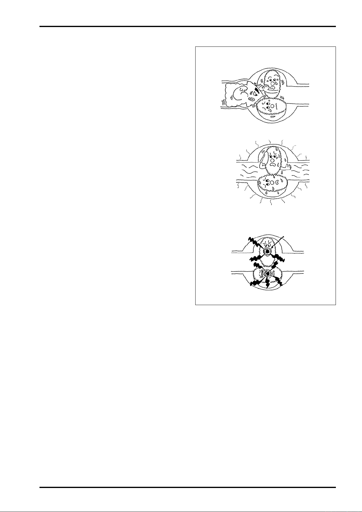
5.2 Operating Precautions
(1) When changing owrates:
In applications where the owrate varies or
where shutoff valve opening and closure takes
place in batch operation, avoid rapid changes
in owrate across the meter.
Operating the meter at owrates in excess of
the maximum allowable owrate will nullify the
guaranteed accuracy, reduce the meter life and
may result in faulty conditions, such as burn
of bearings or rotor-to-measuring chamber
contact.
(2) Where the temperature of metered uid
changes:
Avoid rapid temperature changes in the meter.
Temperature changes of the uid in the meter
should be held with in 3℃ perminute.
Extra care should be used particularly when
making a ow measurement in batch operation
without the provision of heat tracing of the
tubing where the fuid temperature differs from
atmospheric temperature.
f rapid temperature changes are anticipated,
I
heat trace the tubing assembly as well as
the meter.
(3) Liquids of low steam pressure:
iquids with low viscosity and low steam
L
pressure can easily v a p o r i z e a nd th e ir
temperature and pressure should therefore
be strictly controlled.
During operation, the temperature of bearings
in the meter usually runs higher than that of
the metered uid. Vapors around the bearings
can present problems, such as unusual noise
and bearing seizure.
(4) Highly corrosive liquids:
When you make a measurement of highly
corrosive liquids, appropriate materials should
be used for tanks and tubing assembly.
Heterogeneous materials originally contained
in the metered fluid, or certain substances
that have leaked out of the tanks and/or
tubing of inappropriate materials, may lead to
costly downtime, as a result of locked rotors,
for example, when they are allowed into the
measuring chamber.
S-176-9-E
Excessive flow Rapid flow variation
××
Rapid temperature variation
Take precautions
against bearing burn!!
×
7
Page 8

S-176-9-E
CAUTION
5.3 Safety Precautions Before Operation Shutdown
(1) Valves should be closed progressively.
Rapid valve closure could, under certain tubing conditions, cause a sharp pressure rise by water
hammer, or hydraulic shock, which can result in damage to the meter.
(
2) Precautions against pressure buildup on closure
Complete closure of valves upstream and downstream of the meter creates a totally enclosed
space between them and a rapid buildup resulting from a rise in atmospheric temperature can be
a potential source of damage to the meter.
(3) Liquids ready to adhere or gel
With liquids that tend to adhere, solidify or gel when allowed to reside, ush away the metered
liquids thoroughly with appropriate detergent from the interior of meter before shutting down
meter operation. Negligence of this precaution and leaving the meter as it is, you may possibly
have problems when you want to start the meter the next time.
8
Page 9
S-176-9-E
6. DISASSEMBLY AND INSPECTION
While recommended servicing intervals vary according to the given operating conditions, the
◎
eneral rule to follow is to perform periodic disassembly and inspection once a year.
g
Refer to the exploded views on pages 12 to 14.
◎
6.1 Meter Body Disassembly and Inspection
Complaint - Fluid will not run.
The most likely cause is that scales become jammed in the oval rotors, making them immovable
and blocking the uid ow.
CA
①
UTION: Be sure to turn off power before you start servicing.
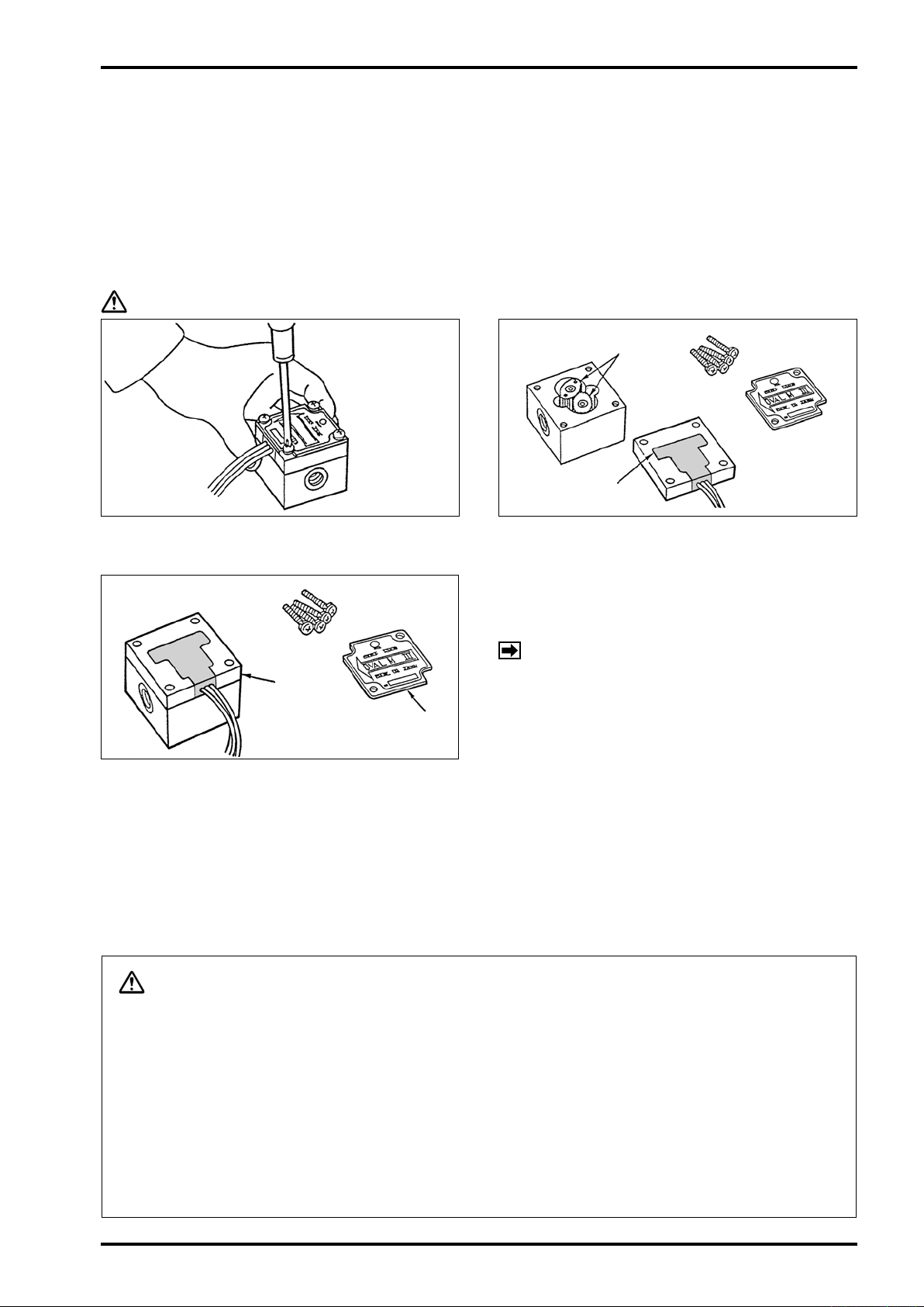
Take off all four pan head with cross point
screwdriver.
Pan Head Screws
Front
Cover
Nameplate
With pan head screws taken off, the front cover
②
and pulse generator are now separable from
the meter body. Be careful not to drop the meter
body.
Rotors
Pulse Generator
With the front cover removed, the measuring
③
chamber and oval rotors are accessible.
Remove the oval rotors from the measuring
④
c
hamber and inspect individual component
parts for condition.
NOTE:The rotor shafts should be drawn out
axially.
(a) Are oval rotors jammed by foreign solids?
(b) Are rotors, shafts and other components
worn?
(c) Are the inner walls of measuring chamber
and front cover damaged?
(d) Are signal generating magnets rusted?
Upon completion of these inspections, wash
clean the oval rotors, rotor shafts, measuring
chamber and front cover thoroughly with fresh
water or cleaning oil.
CA
UTION
1. Deep scoring, high spots caused by impressions, or other irregularities, should be
reconditioned to be smooth and flat with oilstone.
Ⅲ
2. FLOW MATE (OVAL M-
) is a precision instrument. Disassembly and inspection should
be conducted indoors as a general rule. If it is desired to make disassembly and
inspection without removing the meter from the tubing assembly, reduce internal pressure
in the tubing assembly completely to zero, shut off valves upstream and downstream of
the meter completely, drain the tubing assembly and then place a suitable liquid receptacle
immediately below the meter. Use extra care to keep out dirt, sand or other contaminants from
disassembled component parts.
9
Page 10
S-176-9-E
6.2 Meter Body Assembly
Precautions Before Assembly:
Wash clean oval rotors, inner walls of rotor shaft bearings, measuring chamber and inlet/
outlet ports thoroughly to remove dirt, sand and other contaminants completely.
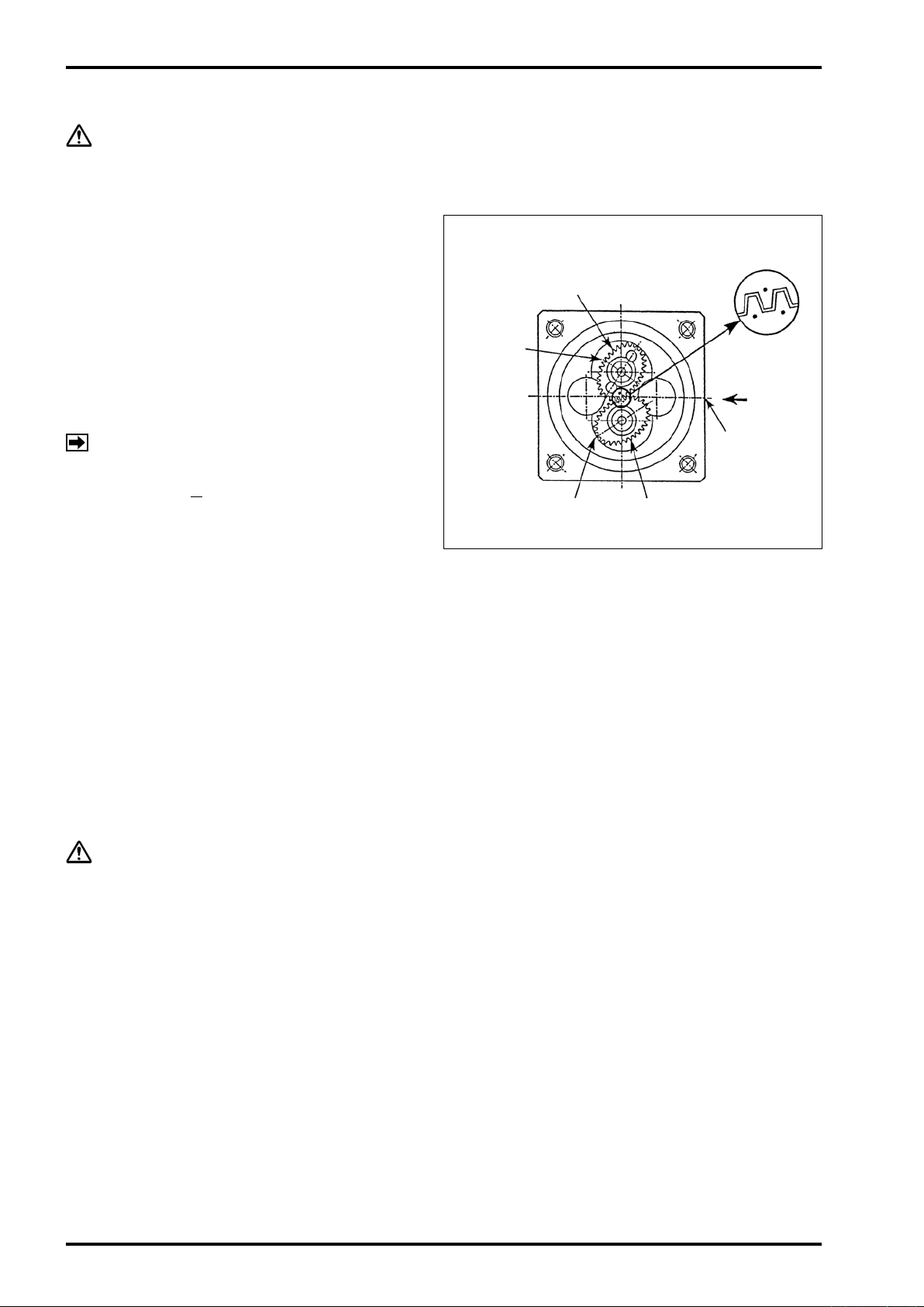
(1) Rotor installation
Installation is correct with the signal generating
magnet embedded side facing the front cover.
●
The rst rotor (match mark “
”) installs on the
upper shaft when the flow direction is from
right to left.
● ●
The second rotor (match mark “
”) installs
on the lower shaft. Install the rotors carefully
with match marks as shown in the inset.
First Rotor
Minor Axis
Match Marks (※)
Flow Direction
NOTES
(※): Match marks are stamped only on product
1.
code “LSF
Match marks do not appear on rotors of material
2.
□□C□−□□
”(metal rotors).
Major Axis
Second Rotor
“IN”
Metal Stamped
K (special resin) or P (PPS resin, PEEK resin).
Verify proper gear engagement at step (2) below.
(2) Conrming the rotor engagement
Hand rotate the rotors at least one complete revolution to see that they are correctly engaged.
(3) Front cover installation
Firstly, install the O-ring in place. If the O-ring is damaged or swollen by the metered uid, it may
not seat properly in the front cover groove. If this is the case, replace it with a new one.
Install four pan head screws and tighten them uniformly until the front cover is rmly secured to
the meter body.
(4) Checking smooth rotation
Check smooth rotation of the rotors and proper output pulse counting with the connected
receiving instrument by allowing air or water into the meter.
CAUTION
Rotation check should be conducted within a range of slow rotor rotation.
Allowing the rotors to spin too fast will lead to burn or other damage to the components.
10
Page 11

7. TROUBLESHOOTING
PROBLEM POSSIBLE CAUSE HANDLING
S-176-9-E
1. Flowrate low. 1. Open valves progressively.
1. Counter will not count
2. Liquid leaks.
2. Pump pressure or head
pressure low.
3. Power source voltage is out
of specication.
4. Oval rotors are jammed by
foreign matter
ow.
5. The oval rotors are installed
the wrong way
1. Incomplete seal of the tubing.
2. Incomplete front cover seal
of the meter body.
, interrupting the
.
2. Taking pressure loss of the
entire tubing system into
account, select a proper pump
pressure or head pressure.
3. S
upply 12 to 24 VDC power to the
pulse generator.
4. Disassemble the meter body
by referring to the meter body
disassembly and inspection
procedure in Section 6. Wash
clean the rotors and related
components.
5. Install the rotors correctly,
referring to the meter body
assembly and inspection
procedure in Sec. 6.2.
1. Tighten up the tube connections
or replace gaskets.
2. Check front cover tting bolts
for tightness and replace O-ring
with new one.
3. Counts while the
valve remains closed.
4. Accumulated total too high.
5. Accumulated total too
low.
1
. Liquid leaks from valves or
tube connections.
2. Air builds up somewhere
between the valve and meter;
pulsating pump pressure
causes a rocking motion of
the rotors.
1
. Rocking motion of rotors by
pulsating ow.
2. Inuenced by external
magnetic elds.
(The owsensor picks up
external magnetic elds from a
motor
3. Air entrapped. 3. Provide an air vent.
1. Inuenced by external
magnetic elds.
, generator, etc.)
1. Inspect valves and tube
connections for condition.
2. Let the air escape. Provide a
check valve and accumulator.
1. Provide a check valve and
accumulator.
2. Shield from external magnetic
elds.
. Shield from external magnetic
1
elds.
11
Page 12
S-176-9-E
MODEL
Su per Mic r
o
MAD E I N JA
PAN
mL
/
P
LSF38
NO.
TOP
OUT
IN
BOTTOM
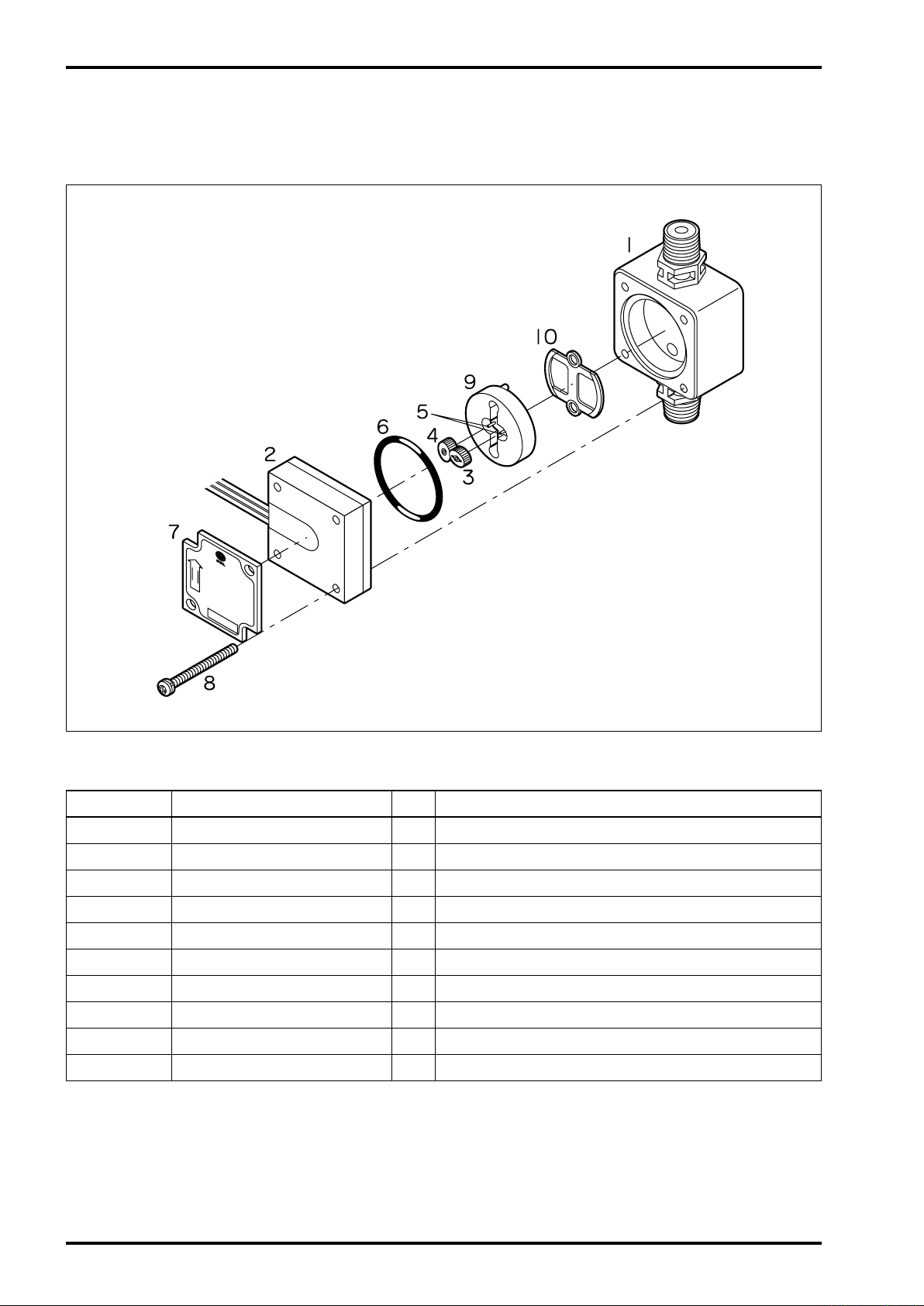
8. EXPLODED VIEWS AND PARTS LISTS
8.1 Meter Size 38
Exploded View
◇
◇
Parts List
◇
◇
Symbol No. Part Name Q'ty Remarks
1 Meter Body 1
2 Front Cover with MR Sensor 1 Molded MR sensor built in (lead wires
3 First Rotor 1 Signal generating magnet embedded
4 Second Rotor 1
5 Rotor Shaft 2 Press t into the inner case
6 O-Ring 1 S-3
2
7 Nameplate 1
8 Screw 4 M4×35 washer, hex nut provided
9 Inner Case 1
0 Inner Case Retaining Gasket 1
1
◦
When ordering replacement parts, please specify the product No., owmeter model,
instruction manual No., symbol No., part name, quantity desired, etc.
200mm)
12
Page 13
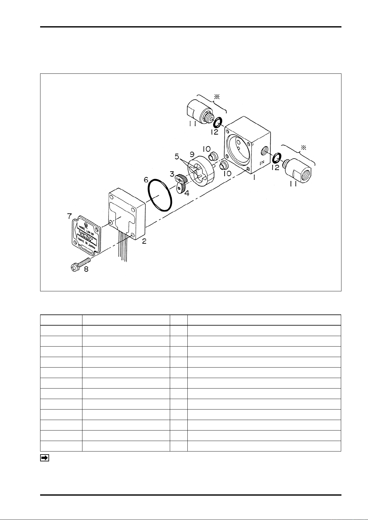
8.2 Meter Size 39
Exploded View
◇
◇
S-176-9-E
※
Option
Parts List
◇
Symbol No. Part Name Q'ty Remarks
1 Meter Body 1
2 Front Cover with MR Sensor 1 Molded MR sensor built in (lead wires
3 First Rotor 1 Signal generating magnet embedded
4 Second Rotor 1
5 Rotor Shaft 2 Press t into the inner case
6 O-Ring 1 S-3
7 Nameplate 1
8 Screw 4 Washer provided (M4
9 Inner Case 1
1
※
※
NOTE :※Option
●
When ordering replacement parts, please specify the product No., flowmeter model,
instruction manual No., symbol No., part name, quantity desired, etc.
◇
2
20)
×
0 Seal Cap 2
11 Fitting 2 300 mesh net incorporated
12 O-Ring for Fitting 2 S-
10
200mm)
13
Page 14
S-176-9-E
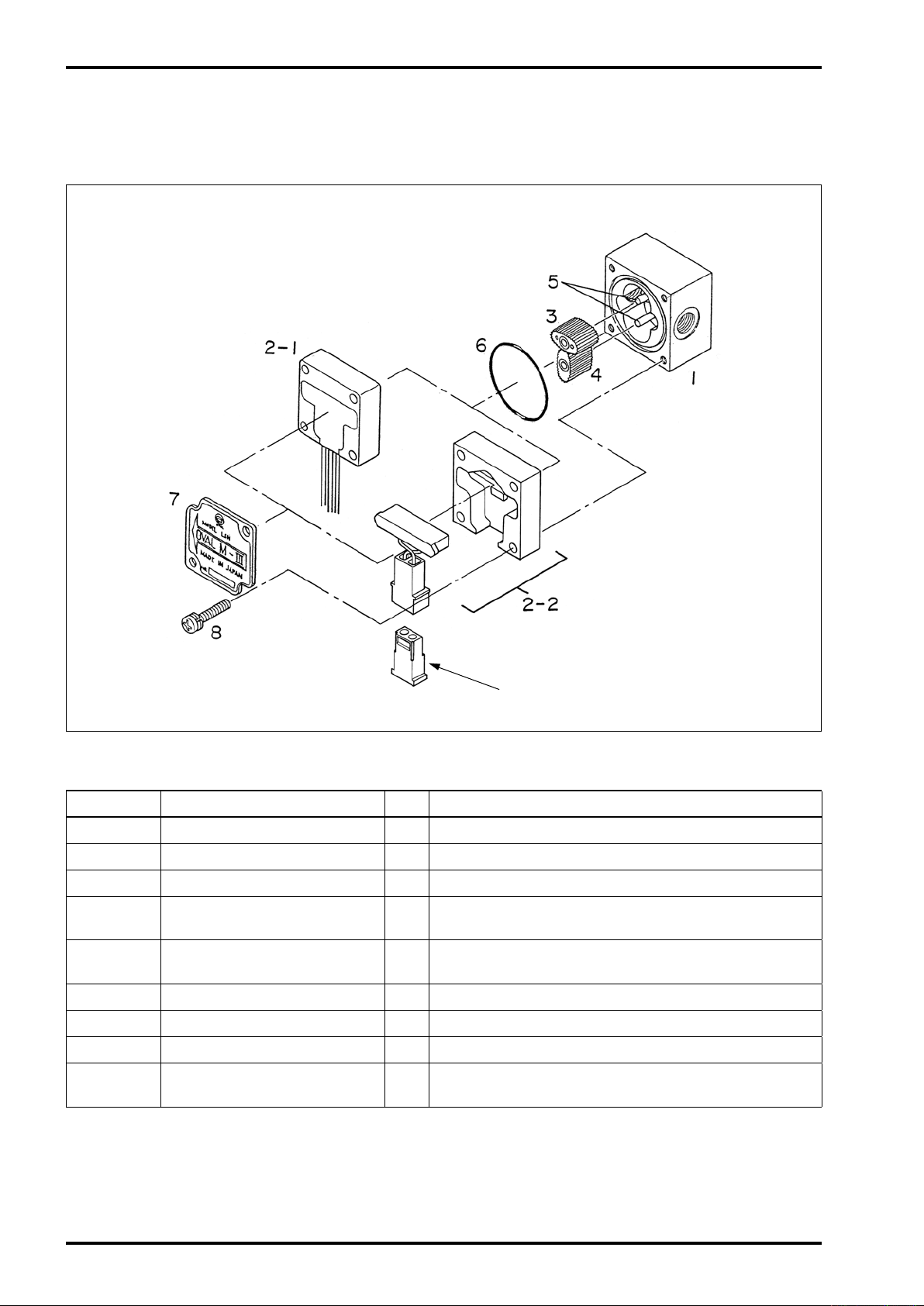
8.3 Meter Sizes 40, 41 and 45
Exploded View
◇
◇
Connector
Parts List
◇
Symbol No. Part Name Q'ty Remarks
◦
When ordering replacement parts, please specify the product No., owmeter model,
◇
1 Meter Body 1
-1 Front Cover with MR Sensor 1 Molded MR sensor built in (lead wires
2
2-2 Front Cover with Reed Switch 1 Connector provided
3 First Rotor 1
4 Second Rotor 1
5 Rotor Shaft 2 Press t into the meter body with built-in O-ring
6 O-Ring 1 Meter sizes 40, 4
7 Nameplate 1
8 Screw 4
With bearing and signal generating magnet
(Meter size 40 without bearings)
With bearing
(Meter size 40 without bearing)
1: S-32 ; Meter size 45 : S-42
Washer provided
(Meter sizes 40,
41: M4
×20 ;
Meter size 45: M5
instruction manual No., symbol No., part name, quantity desired, etc.
200mm)
×25)
14
Page 15
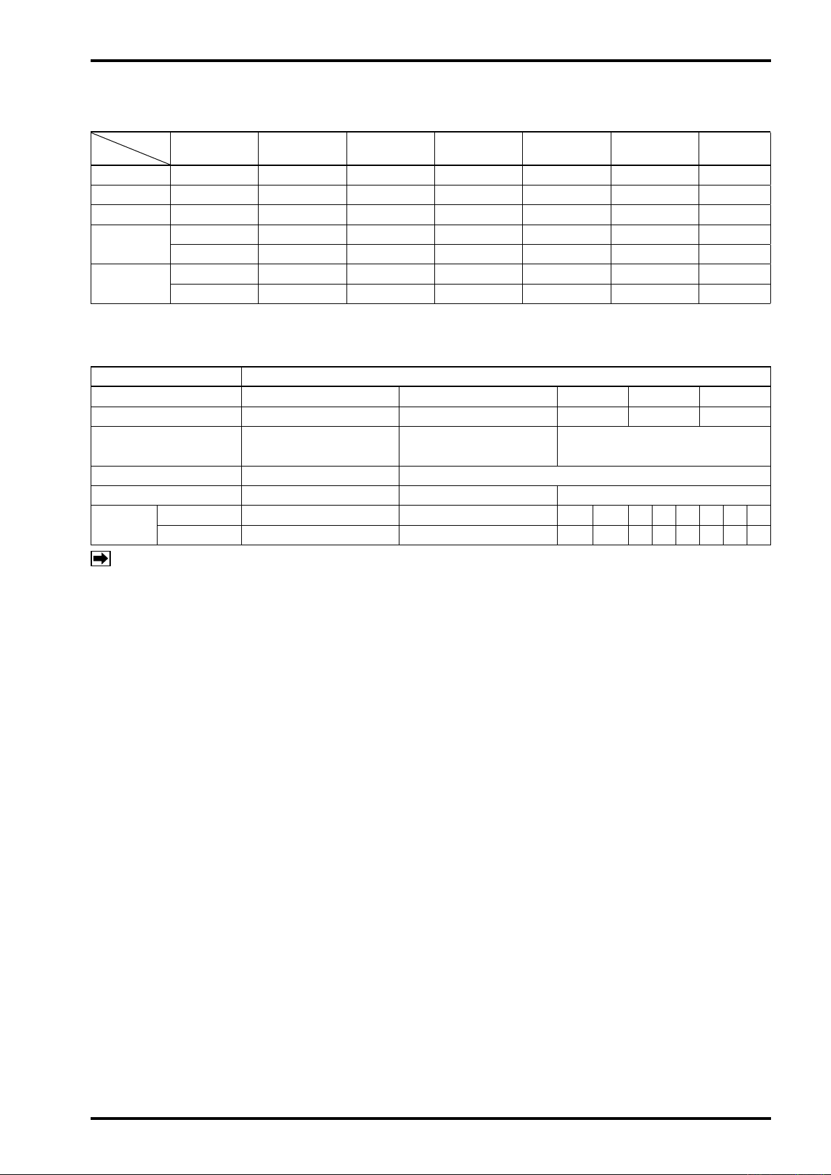
9. GENERAL SPECIFICATIONS
S-176-9-E
(1) Flow Ranges
Viscosity
Meter Size
Super Micro 38
Super Micro 39
40
41
45
Water
0.09 to 3
― ―
―
―
―
―
―
0.3mP
a・s to less
than 0.8mP
― ― ― ― ―
1.5 to 50 1.0 to 50 0.7 to 50
3.0 to 100 2.0 to 100 1.5 to 100
7.0 to 100 4.0 to 100 2.0 to 100 1.0 to 100
10.0 to 500 7.0 to 500 4.0 to 500
25.0 to 500 15.0 to 500 7.0 to 500 3.5 to 500
a・s
0.8mP
a・s to less
than 2.0mP
0.12 to 6 0.12 to 6
a・s
2.0mP
than 5.0mP
a・s to less
a・s
5.0mP
a・s to less
than 200mP
a・s
― ―
―
―
―
5.0mP
a・s to less
than 1000mP
0.5 to 50 Special resin
1.0 to 100 Special resin
―
2.5 to 500 Special resin
―
(2) Meter Body
Item Description
Meter Size Super Micro 38 (※1) Super Micro 39 40 4
Connections/Nominal Dia R
Accuracy
0.09 to less than 0.18L/h ±10% RD
0.18 to 3L/h ±3%RD
1/4 male
G1/8(w / tting: Rc1/4 (※3))
Rp1/8 (6mm) Rp1/8 (6mm) Rp1/4 (8mm)
0.12 to less than 0.3L/h ±8% RD
0.3 to 6L/h ±3% RD
±1% of reading
Operating Temp. Range −10 to +60℃ −20 to +80℃
Max. Operating Pressure 0.3MPa 0.49MPa 0.98MPa
Material
(※2)
NOTES: ※1
Meter Body P C L C L C C L C C
Rotors P P K K K K C K K C
. Acceptable physical orientation of Meter Size 38 is bottom to top only.
2. C: Stainless steel (basic body SUS316; rotors SUS316 sintered)
※
L: Aluminum + anodized aluminum (Meter material “L” is not serviceable for water and
corrosive liquids.)
K: Special resin
P: PPS resin (For applications other than water, pure water, and oils, consult the factory.)
P: PEEK resin (water and pure water only) Meter Size 38 only.
3. Fittings furnished with Meter Size 39 have a built-in 300 mesh net.
※
1 45
Unit in L/h
a・s
PEEK resin
PPS resin
Stainless steel
Stainless steel
Rotor
Material
15
Page 16
S-176-9-E
H
L
[supply volt.] 2VDC min.
1VDC max.
H
L
6.2 to 7.6VDC
0.5VDC
4.0
≦
H
×
H L
+
100≦65.0
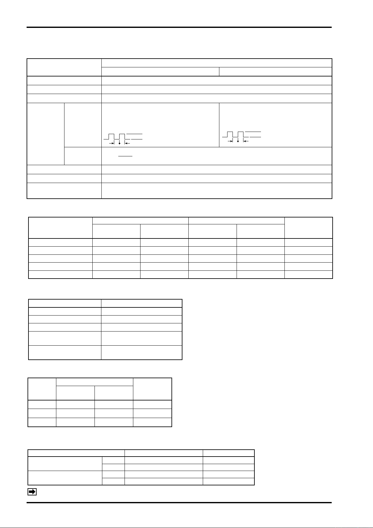
(3) Pulse Generator
1. MR Sensor (standard)
Item
Method of Detection A magnetoresistive (MR) sensor converts alternating magnetic elds to a voltage output.
Speed of Response 1
Ambient Temp. Range –20 to +80℃
Voltage pulse
Output Pulse
※
Duty
ratio(%)
Transmission Length 1 kilometer max. (cable used is CVVS 1.25 to 2.00mm2)
Power Source 12 to 24VDC ±10%
Current Drain
(power consumption)
000Hz max. (MR sensor alone)
Voltage pulse
“0” / “1” = 1VDC max. / [supply volt.] – 2VDC min.
(resistive load 10kΩ min.)
0mA max. (0.3W max.)
1
Meter Size 38 Meter Sizes 39, 40, 4
Description
Voltage pulse
“0” / “1” = 0.5VDC max. / 6.2 to 7.6VDC
(resistive load 10kΩ min.)
Unit in L/h
1 and 45
Measurement units of output pulses (MR sensor models)
※
Factored Pulse Unfactored Pulse
Meter Size
Super
Micro 38
Super Micro 39
40 1 13.9
41 1 27.8
45 10 13.9
2. Reed Switch
Item
Max. operating voltage AC: 45V; DC: 45V
Contact current capacity 1
Contact withstanding voltage DC:
Output pulse
Operating ambient temp.
Measurement units of output pulses (reed switch)
※
Meter
size
40 0.5 2
41 1.0 27.8 100
45 5.0 2
※
Unfactored Pulse
Nom. meter
factor mL/P
Pulse unit mL/P
― ―
― ―
(excluding options / Meter Sizes 38, 39)
Description
0W or 0.5A (resistive load)
250V R.M.S. for one min.
Contact-closure pulse
(unfactored pulse only)
–20 to +85℃
(relative humidity 90% max.)
Freq. at max.
owrate Hz
7.8 50
7.8 500
Freq. at max.
Max. owrate
L/h
owrate Hz
Nominal
0.0550 15.2 3
0.161 10.4 6
0.
0.5 55.6 1
meter
factor mL/P
25 55.6 50
2.5 55.6 500
Freq. at max.
owrate Hz
Max. Flowrate
L/h
00
(4) Applicable Standards
Pulse Generator MR Sensor Reed Switch
Applicable EU Directives
Applicable EN standard
NOTE: To meet compliance requirements, a lightning protector (M SYSTEM: MDP-SP or equiv.) must be used.
16
RoHS 2011/65/EU 2011/65/EU
EMC 2014/30/EU —
RoHS EN50581:2012 EN50581:2012
EMC EN61326-1:2013 Class A —
Page 17
S-176-9-E
200
R
10.8
□
44
84
42.1
31.3
Hexnut
16acrossflats
200
2-Rp
33.8
25.8
8
□
40
200
Rc
8
□
40
83
43.8
35.8
G
(Iffittingisprovided,
option)
※A#300netisbuilt
inRc
fitting.
(Iffittingisnotprovided)
□
50
200
49.3
30.8
18.5
200
2-Rp
2-Rp
33.8
25.8
8
□
40
200
Rc
8
□
40
83
43.8
35.8
G
(Iffittingisprovided,
option)
※A#300netisbuilt
inRc
fitting.
(Iffittingisnotprovided)
200
2-Rp
33.8
25.8
8
□
40
4-A
45°
φB
10. OUTLINE DIMENSIONS
■
MR sensor generator equipped
●
Super Micro 38
NOTE: For lead wire connections, see Sec. 4.2 on page 5.
●
Super Micro 39
NOTES: 1. For Meter Size 38, prepare a strainer (mesh #300). Meter Size 39 without tting requires a
strainer (mesh #300).
2. For lead wire connections, see Sec. 4.2 on page 5.
●
Meter sizes 40 and 41
●
Meter size 45
All dimensions in millimeters
NOTE: For lead wire connections, see Sec. 4.2 on page 5.
●
Mounting dims.
Meter size A B Scr. depth
39 M4 45 6
40 M4 45 6
4
1 M4 45 6
45 M5 56 1
5
Fig. 10.1
17
Page 18
S-176-9-E
MODEL LSF41
MADE IN JAPAN
OVALM-Ⅲ
□40
25.8
2-Rp
1
/
8
33.8
8
MODEL LSF45
MADE IN JAPAN
OVALM-Ⅲ
□50
30.8
2-Rp
1
/
4
49.3
18.5
L
A
H
L
A
H
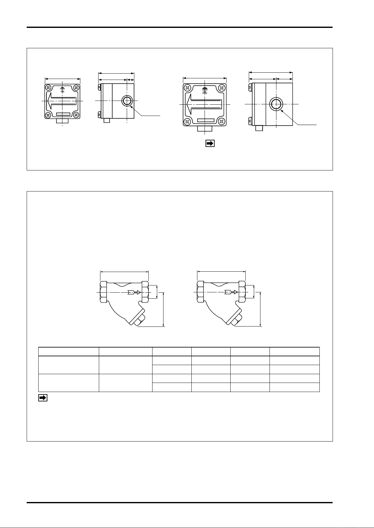
■
Reed Switch Generator Provided
●
Meter sizes 40 and 41
■
Strainers (YS12 and 13)
Applicable meter sizes: 40, 41 and 45
Max. operating pressure: 1.96MPa
Body material: FCD450 (ductile cast iron) ※Material: H
SCS14A (stainless steel) ※Material: C
Net material : SUS304 (stainless steel) ※Material: H
SUS316 (stainless steel) ※Material: C
●
Fig. 10.2
Meter sizes 45
NOTE: See Sec. 4.2 (page 5) for lead-
wire connections.
All dimensions in millimeters
●
Outline (Material C)
All dimensions in millimeters
●
Length Table
●
Outline (Material H)
Category Nominal size A Material L H (approx.) Net Mesh No.
2
YS12 (for Meter Sizes
40 and 41)
YS13 (for Meter Size
45)
NOTES
1:
Meter Sizes 40 and 41 with R1/4×Rc1/8
※
Rc1/8 (6mm)
Rc1/4 (8mm)
1
※
H 110
C 95
H 80 60 2
C 65 50 2
bushings.
※
2
※
60 200
50 200
(Bushings are contained in the same package as the strainer.)
2:
Dimensions with bushing installed (for reference purpose).
※
Fig. 10.3
00
00
18
Page 19
S-176-9-E
11. PRODUCT CODE EXPLANATION
●
Flow Mate
Item
Model L S F FLOW MATE (OVAL M-Ⅲ)
Meter Size
Major Parts Materials
Process Connection (ttings)
Pulse Generator
Pulse Type
① ② ③
Product Code
④ ⑤ ⑥ ⑦ − ⑧ ⑨
3 8 R
3 9
4 0 Rp
4 1 Rp
4 5 Rp
P Meter body (C) + Rotors (P: PEEK resin) Meter size 38 only
P Meter body (C) + Rotors (P: PPS resin) Meter size 39 only
C Meter body (C) + Rotors (C)
L Meter body ( L) + Rotors (K)
P Meter body (C) + Rotors (K)
0 − Less ttings
8 − Fittings provided (option)
M MR sensor
R Reed switch (option)
1 Unfactored
2 Factored (MR sensor only)
Description
1/4 male
G1/8 (Rc1/4 depending on optionally available ttings.
A 300-mesh net is built in.)
1/8 (6mm)
1/8 (6mm)
1/4 (8mm)
NOTE: ○: Available
×
Combination
38 39 40 4
○ ○ ○ ○ ○
○
○
○
○ × × × ×
× ○ × × ×
× × × ○ ○
× × ○ ○ ○
× × ○ ○ ○
○ ○ ○ ○ ○
× ○ ○ ○ ○
○ ○ ○ ○ ○
× × ○ ○ ○
○ ○ ○ ○ ○
× × ○ ○ ○
: Not available
1 45
○
○
Strainer
●
Item
Model Y S M-Ⅲ Strainer
Nominal Dia.
Material
Product Code
① ② ③ ④ ⑤
1 2 Rc
2 3 Rc
1/8 (Fits Meter sizes 40 and 41.)
1/4 (Fits Meter size 45.)
H FCD450
C SCS
14A
Description
19
Page 20

S-176-9-E
All specifications are subject to change whitout notice for improvement.
2017. 09 Revised △
S-176-9-E (1)
 Loading...