

Oval LS5677-5**B Series, LS5377-5**B Series, LS5577-5**B Series, LS4976-5**A Series, LS5277-5**B Series Instruction Manual
...
Ins. No.
S-179-1-E
ELECTRONICS REGISTER PROVIDED
FLOWPET
-5G
Water service
MODEL:LS5277-5 □□B, LS5377-5 □□B, LS5577-5□□B, LS5677-5□□ B
Oil service
MODEL:LS4976-5□ □ , LS5076-5□ □ , LS5276-5□ □ , LS5376-5□ □ , LS5576-5□ □ , LS5676-5□ □
A
B
C
D
A
B
C
D
A
B
C
D
A
B
C
D
A
B
A
B
Ins. No.
S-179-1-E
ELECTRONICS REGISTER PROVIDED
FLOWPET
-5G
Water service
MODEL:LS5277-5 □□B, LS5377-5□□B, LS5577-5□□ B, LS5677-5 □ □B
Oil service
MODEL:LS4976-5□ □ , LS5076-5□ □ , LS5276-5 □ □ , LS5376-5□ □ , LS5576-5 □□ , LS5676-5□ □
A
B
C
D
A
B
C
D
A
B
C
D
A
B
C
D
A
B
A
B
上海洪柯自动化仪表有限公司
OVAL总代理: 上海洪柯自动化仪表有限公司 电话: 021-54485672 网址: WWW.SHAKIC.COM Email: shakic@163.com
S-179-1-E
A great deal of time and care has been devoted to the proper designing, manufacturing and preparation of the
Flowpet-5G for delivery into your hands. We hope that you derive from its operation the full measure of value
and utility to which you looked forward to when you purchased it. Your considerate treatment and care will repay
you well throughout its service life. For these reasons, we suggest you to read this instruction manual
throughly befor use and keep it for your quick reference.
CONTENTS
1. HANDRING PRECAUTIONS ........................................3
1.1 Confirming the Nameplate .......................................3
1.2 Transportation Precautions .......................................4
1.3 Storage Precautions.................................................5
1.4 Installation Location Precautions .............................6
2. OPERATING CONDITIONS ..........................................6
3. GENERAL DESCRIPTION ..........................................7
3.1 Features .................................................................7
3.2 Product Code Explanation .......................................8
3.3 Part Names ..............................................................9
4. PIPING.........................................................................10
4.1 Piping Precautions..................................................10
4.2 Flushing the Piping Assembly................................12
4.3 Lagging Work.........................................................12
4.4 Example of Installations..........................................13
4.5 How to Change the Flow Directions and
Display Orientations................................................15
5. WIRING .......................................................................17
5.1 Field Wiring ............................................................17
5.2 Furnished Leads from the Meter............................18
5.3 Hook-up Diagrams .................................................20
6. DISPLAY AND CONTROLS .......................................22
6.1 Display ...................................................................22
6.2 Display Capabilities and Operation........................23
7. OPERATION..............................................................26
7.1 Operation ..............................................................26
7.2 About Regiater,s Life............................................28
7.3 Battery Life ...........................................................28
8. TROUBLESHOOTING...............................................29
9. DISASSEMBLY AND INSPECTION .........................32
10. EXPLODED VIEW AND SERVICE PARTS LIST .....35
Exploded View.........................................................35
Service Part Lists ....................................................36
11. BATTERY REPLACEMENT AND
PARAMETER SETTING PROCEDURE .................37
11.1 Battery Replacement............................................37
11.2 Parameter Setting Procedure ..............................40
12. GENERAL SPECIFICATIONS..................................50
(1) Flow Range............................................................50
(2) Meter Body.............................................................50
(3) Register, Pulse Generator .....................................51
(4) Units of Registration,Pulse Output Units of
Registration............................................................52
(5) Applicable EN standards........................................53
13. OUTLINE DIMENSIONS...........................................54
(1) FLOWPET-5G.............................................................54
(2) Strainer ..................................................................55
上海洪柯自动化仪表有限公司
S-179-1-E
1. HANDLING PRECAUTIONS
Every unit is thoroughly tested and inspected before shipment from our factory. When recieved, its
appearance should be inspected for possible damage by rough handling during transit. First of all, thoroughly
read the handling precautions described in this section. For topics other than those stated in this section, refer
to respective sections. If at any time in the future you seek our assistance, contact the nearest sales office in
your area.
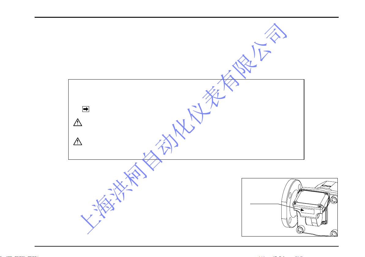
1.1 Confirming the Nameplate
Each FLOWPET is adjusted to individual specifications before shipment
from our factory. Indicated at the bottom of the register is the product code
number and rated specification.
Make sure to see that Product Code Explanation in Section 3.2
and General Specifications in Section 12 conform to your particular
specifications.
Nameplate
● When you inquire, specify the product name, model number, serial
number, ratings/specifications and other information.
Shown in this manual are the signal words NOTE, CAUTION and WARNING, as described in the
examples below:
NOTE: Notes are separated from the general text to bring the user's attention to important information.
CAUTION: Caution statements signal the user about hazards or unsafe practices which could result in minor
personal injury or product or property damage.
WARNING:
Warning statements signal the user about hazards or unsafe practices which could result in severe
personal injury or death.
上海洪柯自动化仪表有限公司
S-179-1-E
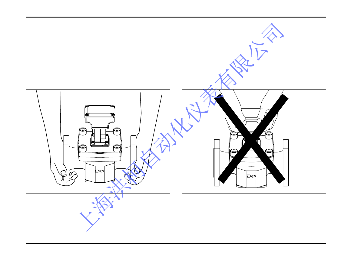
1.2 Transportation Precautions
(1) In order to safeguard against damage during transportation, transport the instrument to the installation
location in the style packaged from our factory if possible.
(2) This instrument is adjusted and inspected as an assembly consisting of the flowmeter, pulse generator
(sensor) and register. It should therefore be handled as an assembly at all times; you should not attempt to
separate the register.
(3) During transit, exercise care not to give impact shocks to the register.
〈Hold like this.〉 〈Don,t hold like this.〉
上海洪柯自动化仪表有限公司
S-179-1-E
1.3 Storage Precautions
If the instrument is to be stored over an extended period of time before installation, it could be involved in unexpected happenings. So if an extended period of storage is anticipated, the following precautions should be taken:
(1) The instrument should be stored in the style packaged in our factory if circumstances permit.
(2) Select a storage location that meets the following reguirements:
* where it is free from rain and water.
* where vibration and impact shocks are least encountered.
* where temperature and humidity in the storage location are as near to the room temperature and humidity
(25℃ and 65% or so).
(3) If you store the instrument which has been placed in service for any length of time, it should be purged with
clean air or N2 gas, etc. to keep the metered material from adhering to the flowmeter couplings, pipeline,
housing, etc.
(4) Use caution to keep the register away from thinner, alcohol or other organic solvents.
Do not attempt to disassemble the register and modify in any way.
(We cannot guarantee performance of modified Flowpet. )
CAUTION
上海洪柯自动化仪表有限公司
S-179-1-E
1.4Installation Location Precautions
(1) In this register, a magnetic sensor is used to pick up magnetic fields of signaling magnets embedded in the
rotor. For this reason, the instrument should be installed sufficiently away from sources generating magnetic
field. If a magnetic valve 10 watts or so is used, separate it at least 10 centimeters from the flowmeter
(depending on operating conditions).
(2) Application in cold regions
To prevent the meter from freezing, install it indoors (in the boiler room, for example).
① A vertical run is recommended for ease of pipeline drainage. Provide a drain plug. (See pipeline drawing
on pages 18 and 19.)
② Lagging is necessary. The register, strainer cover and drain plug should not be lagged, however. Take into
consideration simple and ready separation of the meter from the piping assembly.
(3) This register operates at temperatures between
− 10 to + 60゜C. If exposure to elevated tempera-tures is expected by the direct rays of the sun, reflected
heat, etc., protect the register against heat with a sunshade or heat shield to ensure its operation within the
specified temperature range.
(4) This register is designed for indoor use: install in a location free form rainwater, oil, sunlight.
If exposure to rainwater is unavoidable, provide an appropriate rain guard or sunshade.
2. OPERATING CONDITIONS
To derive the high accuracy and long life from this meter, it is necessary that the meter be used within the
specified conditions in flowrate, pressure, temperature and viscosity. These operating conditions are stated on
the nameplate of flowmeter,s register and in the general specifications in Section 12 of this instruction manual.
Familiarize yourself thoroughly with these instructions before installation and operation.
CAUTION
Under the Measurement Law, this instrument is not serviceable for cer tifying and
authenticating legal transactions.
上海洪柯自动化仪表有限公司
S-179-1-E
7
Nameplate
3. GENERAL DESCRIPTION
The FLOWPET-5G is an OVAL flowmeter primarily intended for use in boiler feed water and fuel oil metering
applications. Field proven accuracy and long life along with the best price/performance and ease of use make
this industrial meter ideal as a dedicated tool for heat control.
3.1 Features
1. Available in two product families - for water service and fuel oil service.
2. Newly designed electronic register shows total flow and instantaneous flow on a digital LCD at the touch of
ode select button. The display angle can be adjusted for better visibility (Adjustable range: 75 degrees upward,
75 degrees downward).
3. The electronic register equipped models have an internal battery (good for 8 years); eliminates the need for an
external power source. (Operation on external power source is recommended for external output equipped
models.)
4. Improved display capabilities compared to the previous EG register.
・LCD character height increased to 14mm from 10mm
・Flow indicator allows user to intuitively check instantaneous flow rate
5. Factored pulse width is variable in 1ms steps with the back side buttons (adjustable 1 to 999ms).
6. Simulated outputs available. (external output equipped meter only) Pulse and analog output can be simulated
at any flow rate for loop tests.
7. Reliable engineering unit pulses for total flow and fast pulse output are available.
8. Analog output available (2-wire, 4 to 20mA)
IMPORTANT: Read this instruction manual thoroughly before you start working on piping and
initiate operation. See Section 4 for piping instructions and Section 7 for operating instructions.
CAUTION
上海洪柯自动化仪表有限公司
S-179-1-E
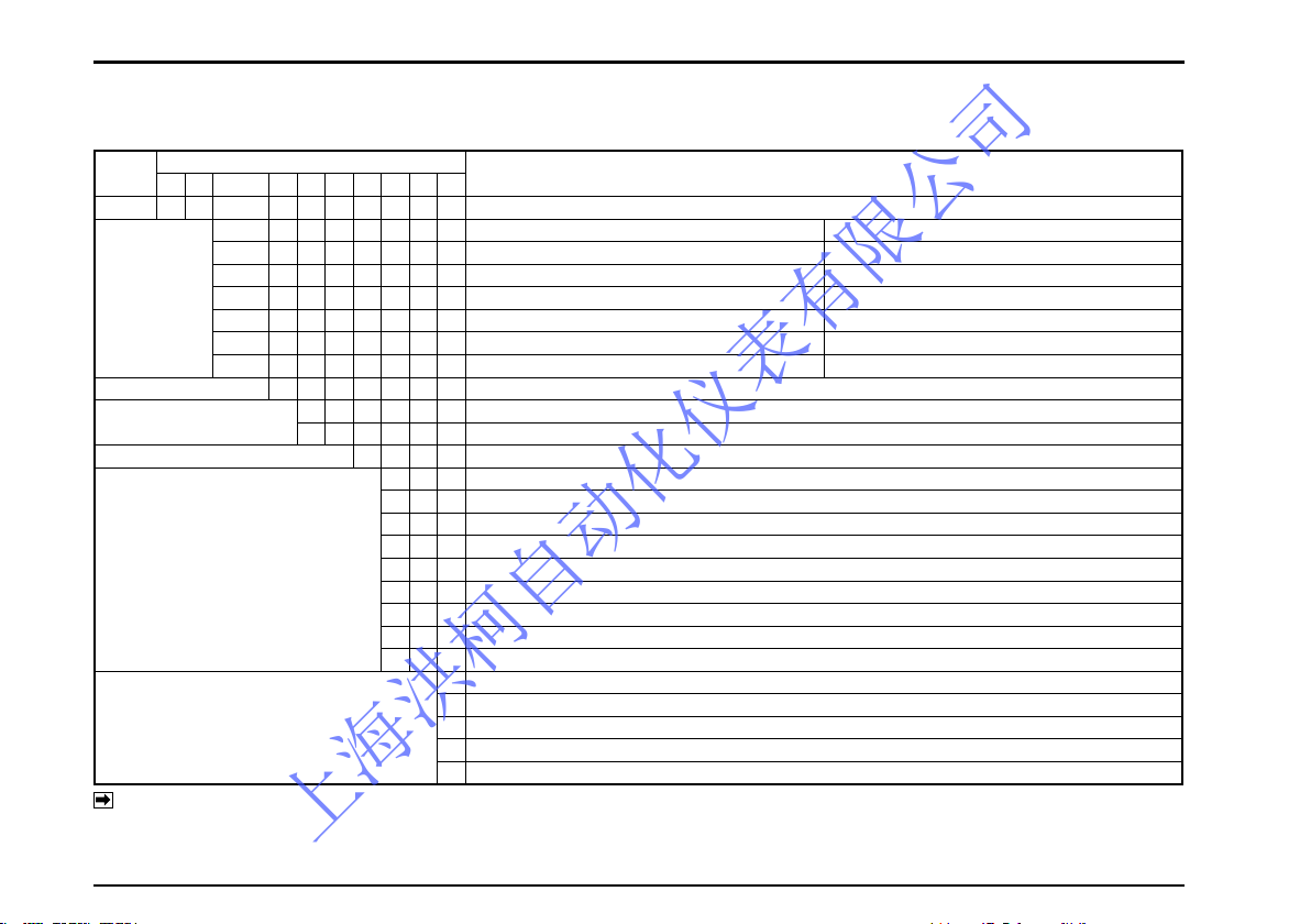
3.2 Product Code Explanation
In this instruction manual, the following combinations of products are described:
Item
Code (Digits)
Description
① ② ③ ④ ⑤ ⑥ − ⑦ ⑧ ⑨ ⑩
Model L S Dedicated Oval flowmeter (Standard model)
Meter Size
(Nominal dia.)
Water service Oil service
4 9 — 20mm (3/4")
5 0 — 20mm (3/4")
5 2 20mm (3/4") 25mm (1")
5 3 25mm (1") 40mm (1•1/2")
5 5 40mm (1•1/2") 40mm (1•1/2") Standard model only
5 6 50mm (2") 50mm (2") Standard model only
Model Name 7 Flowpet
Application
6 − Oil service
7 − Water service
Register 5 Register(5G)
Pulse Generator (※3)
0 0 No output capability (Local display only)
3 0 Factored pulse (pulse width 1ms), +Unfactored pulse (※1)
5 0 Factored pulse (pulse width 50ms), +Unfactored pulse (※1)
6 0 Factored pulse (pulse width 100ms), +Unfactored pulse (※1)
7 0 Factored pulse (pulse width 250ms), +Unfactored pulse (※1)
3 1 Factored pulse (pulse width 1ms), +Unfactored pulse (※1) +Analog output or Analog output only (※2)
5 1 Factored pulse (pulse width 50ms), +Unfactored pulse (※1) +Analog output
6 1 Factored pulse (pulse width 100ms), +Unfactored pulse (※1) +Analog output
7 1 Factored pulse (pulse width 250ms), +Unfactored pulse (※1) +Analog output
Temperature Range
A Oil service: Stndard (0 to 120℃), JIS 10K RF
B Oil service: Stndard (0 to 120℃), ASEM 150 RF
B Water service: Stndard (0 to 120℃), JIS 10K RF
C Oil service: Stndard (0 to 150℃), JIS 10K RF
D Oil service: Stndard (0 to 150℃), ASEM 150 RF
Note: ※1 Unfactored pulse width is xed at 2ms.
※2 If using analog output only, "Factored pulse (1ms) + Unfactored pulse (2ms) + Analog output" will be the specication.
Wire analog output lines (2 lines of the power wire) and leave the ends of pulse output (SIG.1 and SIG.2) cables open (not connected).
※3 Alarm output specication is available as an option.
上海洪柯自动化仪表有限公司
S-179-1-E
9
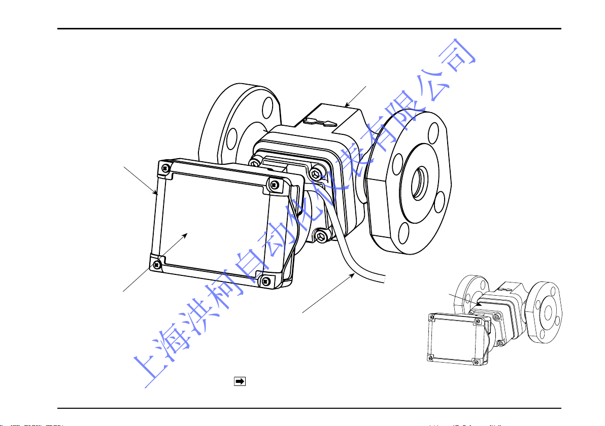
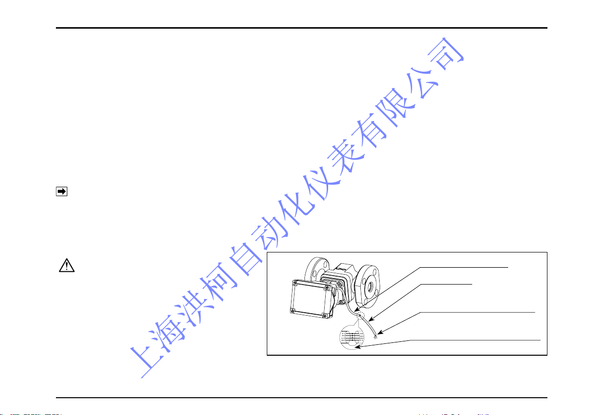
3.3 Part Names
METER BODY
REGISTER
LCD DISPLAY
※ CABLE (1m LONG)
COOLING
BLOCK
HIGH TEMP. MODEL
(NOTE) Only external output equipped meters are furnished with the
cable shown here with an asterisk
※ .
上海洪柯自动化仪表有限公司
S-179-1-E
10
4. PIPING
4.1 Piping Precautions
(1)Install the meter, exercising care to avoid pipe strains.
(2)The meter should be installed downstream of the pump.
(3)Provide a strainer upstream of the meter.
(NOTE)The strainer net used is 80 mesh for nominal size 20mm and 60 mesh for sizes 25 through 50mm.
(4)Install the pump taking into consideration the pressure loss of the entirre piping system. In case where the
material is allowed to flow by means of a head instead of using a pump, a pressure (head) greater than the
pressure loss of the piping system, flowmeter, strainer, etc. should be given.
(5)To prevent inductive interferences, please be sure to connect to the earth ground for instrumentation one of
the four mounting bolts securing the register with the flowmeter body, instead of the ground terminal.
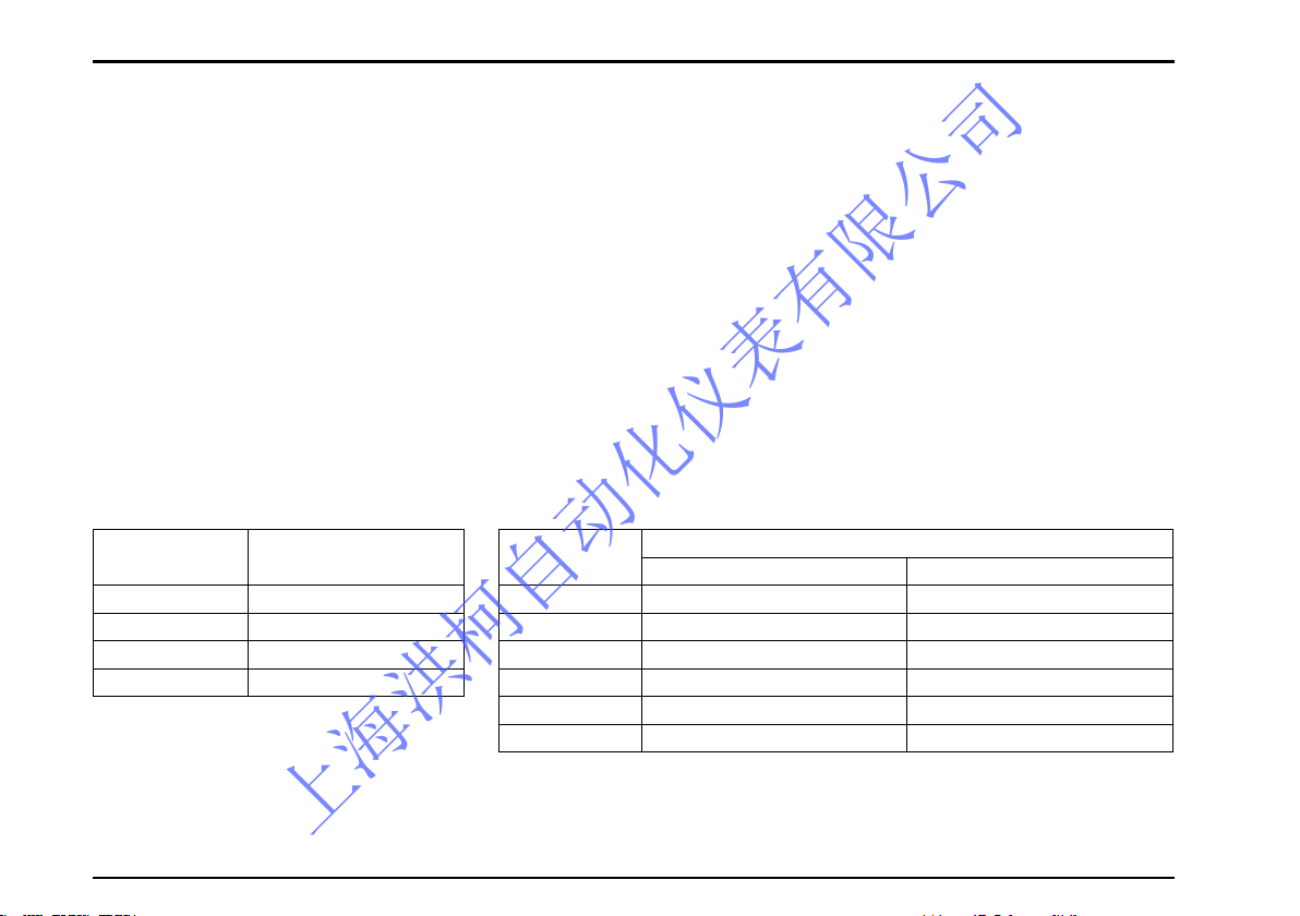
● Pressure Losses of Flowpet
〈Water
Service
〉
Model
Pressure Loss
kPa
LS5277 5 ( 1200 L/h)
LS5377 12 ( 3600 L/h)
LS5577 10 ( 7200 L/h)
LS5677 7 (12000 L/h)
〈Oil
Service
〉
Model
Pressure Loss kPa
Kerosene 1.2mPa•s Heavy oil 19mPa•s
LS4976 32 ( 800 L/h) 47 ( 800 L/h)
LS5076 14 (1600 L/h) 40 (2000 L/h)
LS5276 13 (3000 L/h) 56 (3800 L/h)
LS5376 13 ( 5 m3/h) 30 (6.4 m3/h)
LS5576 25 (11 m3/h) 54 ( 14 m3/h)
LS5676 27 (20 m3/h) 55 ( 24 m3/h)
上海洪柯自动化仪表有限公司
S-179-1-E
11
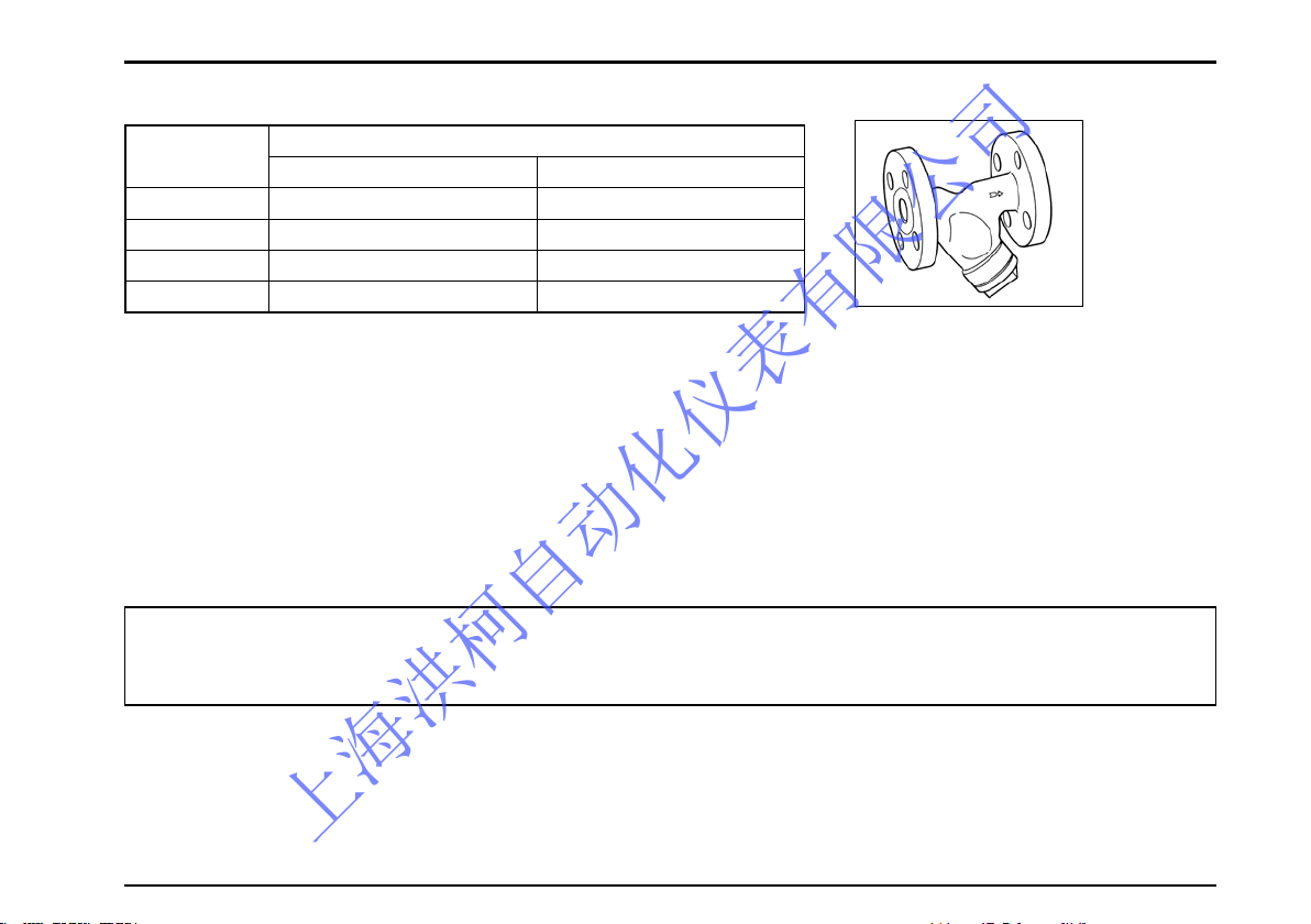
Strainer
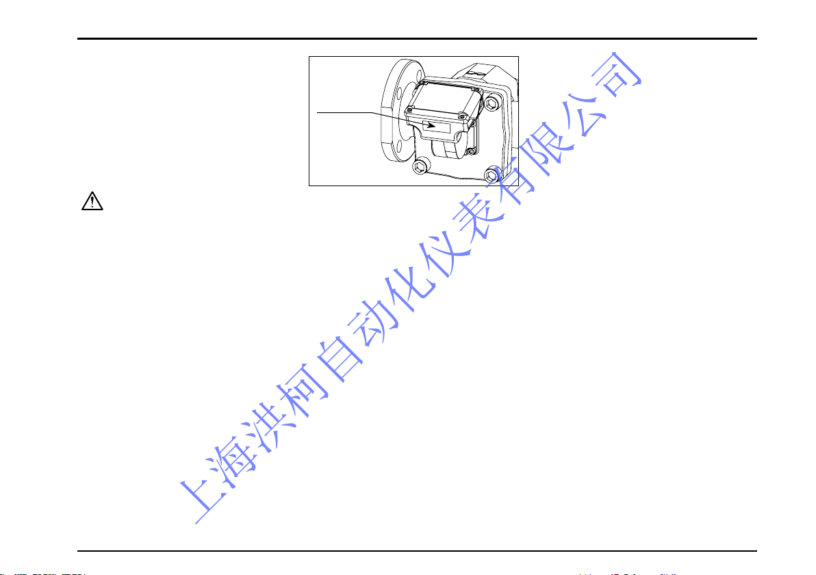
(6) Align the flow direction with the arrow mark on the meter body.
(7) The pulse generator of this meter makes use of the changes in magnetic flux. To minimize influence of exter nal magnetic fields, select an installation location sufficiently away from powerful magnets and conductors
creating strong magnetic fields.
(8) If electric heating is desired, consult factory.
(9) When you conduct a gastight test on the existing piping assembly, careful valve operations sequence is
required to safeguard the rotors against damage due to violent rotor spinning by rushing air currents. Adhere
to the instructions on operation sequence described on page 32.
● Strainer Pressure Losses
Model
Pressure Loss kPa
Kerosene 1.2mPa•s Heavy oil 19mPa•s
LS5278A 6 ( 300 L/h) 50 (3800 L/h)
LS5378A 7 ( 5 m3/h) 28 (6.4 m3/h)
LS5578A 23 (11 m3/h) 26 ( 14 m3/h)
LS5678A 25 (20 m3/h) 40 ( 24 m3/h)
CAUTION: This model is not provided with subtract counter function. In applications where ripples
(to-and-fro motion of the fluid under ripple pressure) or reverse flows exist in the pipeline, the total
counter reading may not be consistent because it adds up flows irrespective of the flow direction.
上海洪柯自动化仪表有限公司
S-179-1-E
1
4.2 Flushing the Piping Assembly
Be sure to remove the meter from the piping assembly and intall a short pipe section in place of the meter.
Flushing the piping assembly with the meter in place will result in serious, costly damage to the meter’s
measuring chamber.
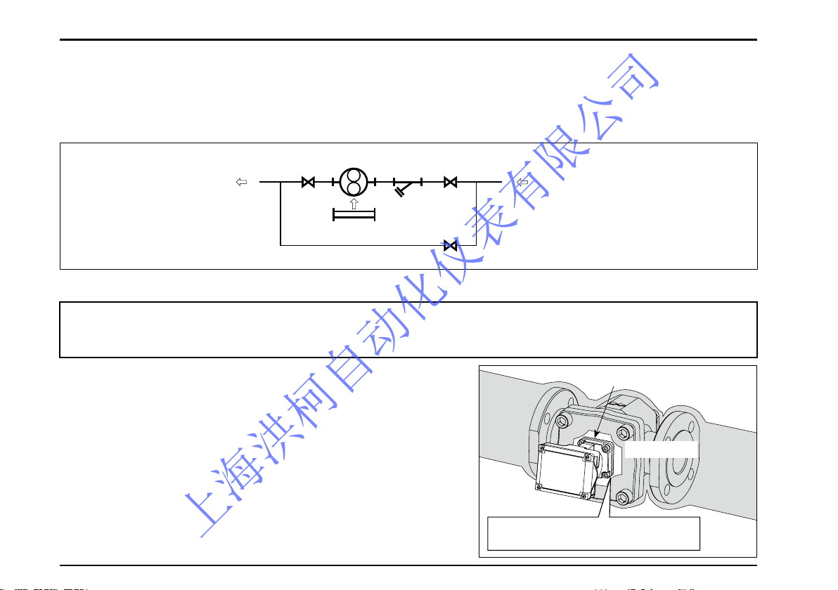
4.3 Lagging Work Precautions
(1) Be sure to inspect for liquid leaks before covering with lagging.
(2) Take into consideration simple and readily disassembly and
inspection for the lagging of the meter.
(3) Strainer should be lagged for quick top cover removal.
Strainer net should be cleaned on a regular basis.
(4) Register and pulse generator must not be lagged. If they
are lagged, temperature will rise to an excessive level and
result in costly damage (see figure on the right).
(5) Heat insulation should not cover up the front cover register
seat.
(6) In applying heat insulation, take into account the ease of
removal and disassembly.
Register Fitting Seat
Allow a clearance around the register
fitting seat for heat retention.
Lagging Seat
FLOW DIRECTION
STRAINER
SHORT PIPE
BYPASS LINE
VALVE
METER
For applications where the meter is to be placed in service in cold regions or where
solidifying materials (e.g. Heavy oil) are to be metered, lagging work for the flowmeter and
strainer is required.
上海洪柯自动化仪表有限公司
S-179-1-E
1
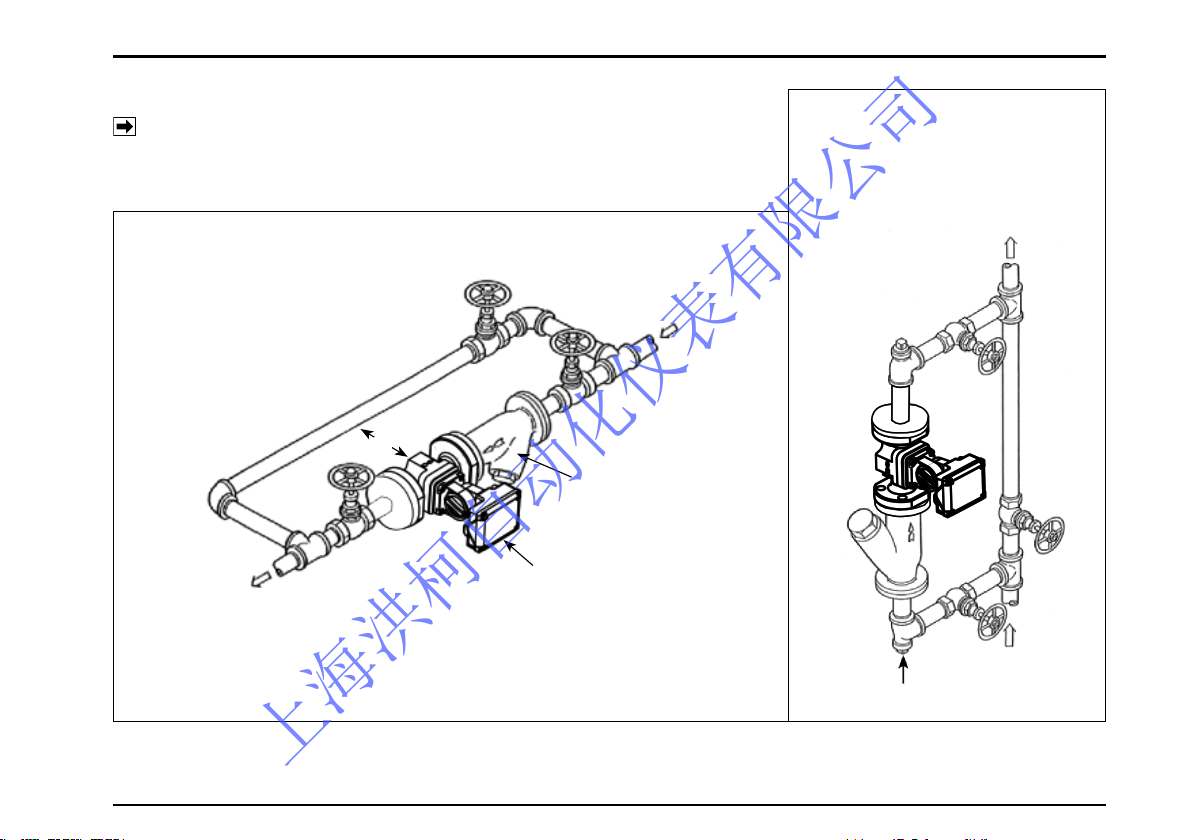
4.4 Examples of Installation
NOTE: Make pipe connections observing the instructions under the
topic“Piping Precautions”on Section 4.1.
●
Vertical Line
Install in the bypass side to prevent scales falling from top of the
piping assembly.
Marked ※ is the space required for disassembly and inspection.
Secure at least 600mm.
● Horizontal Line...........standard piping
BYPASS
IN
STRAINER
FLOWPET-5G
IN
OUT
DRAIN VALVE
OUT
※
上海洪柯自动化仪表有限公司
S-179-1-E
1
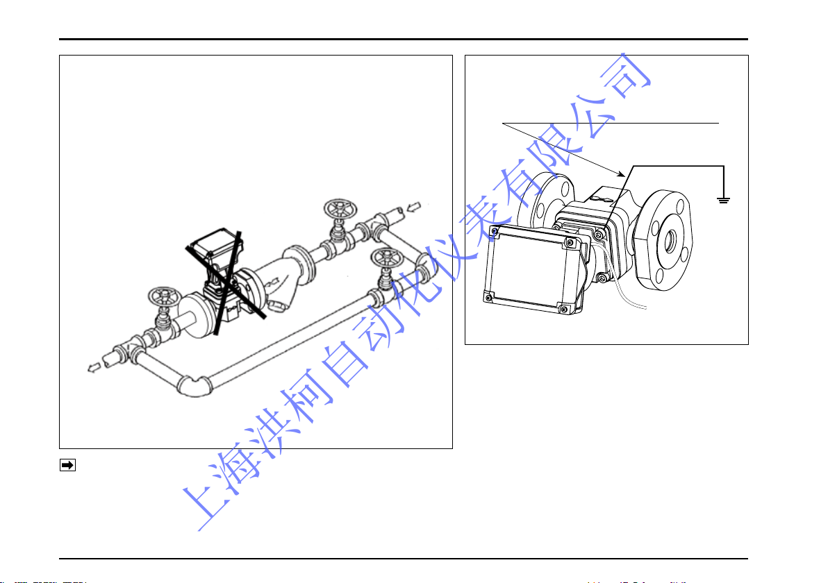
●
Example of Incorrect Piping
◎
Do not install the meter in a position like this.
(Installation is correct if the measuring chamber is on a level
plane.)
To change flow directions, register face directions, see Section 4.5 (2).
If the flowmeter is equipped with external output capability, make electrical connections according
to the wiring instructions in Section 5.
WRONG
●
How to prevent inductive interferences
Connect to the earth ground by using
one of the mounting bolts
BYPASS
STRAINER
FLOWPET-5G
IN
OUT
(Note)
上海洪柯自动化仪表有限公司
S-179-1-E
1
ARROW MARK
( )
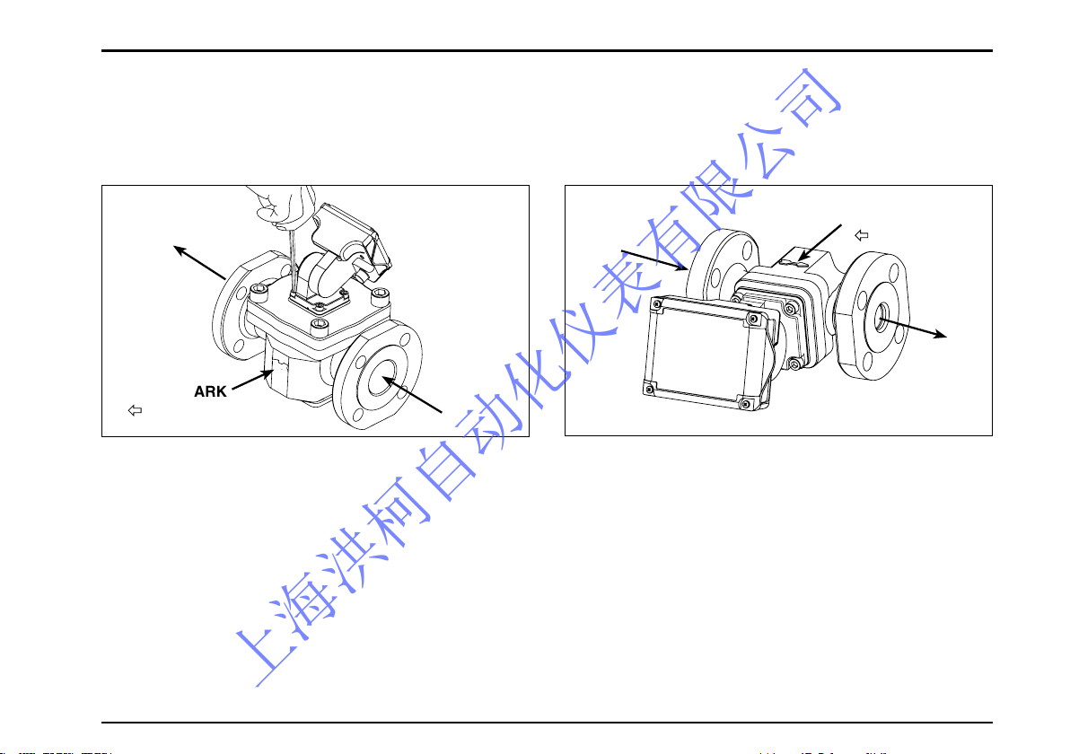
4.5 How to Change the Flow Directions and Display Orientations
(1) How to change the flow directions
The Flowpet is assembled to accept the flow from right to left. Flow directions can simply and readily be
changed in the following manner:
①Remove the meter from the pipeline and separate
the register from the meter body. Aligin the arrow
mark indicating the flow direction with the flow
direction. In case of changing the flow direction
from R-to-L to L-to-R, turn the meter body as shown
in the sketch and reinstall in the pipeline.
OUT
IN
IN
OU
T
ARROW MARK
( )
②Align the physical orientation of the register correct-
ly as shown and retighten the bolts. The same
applies to changing the directions from L-to-R to
top-to-bottom or bottom-to-top.
上海洪柯自动化仪表有限公司
S-179-1-E
1
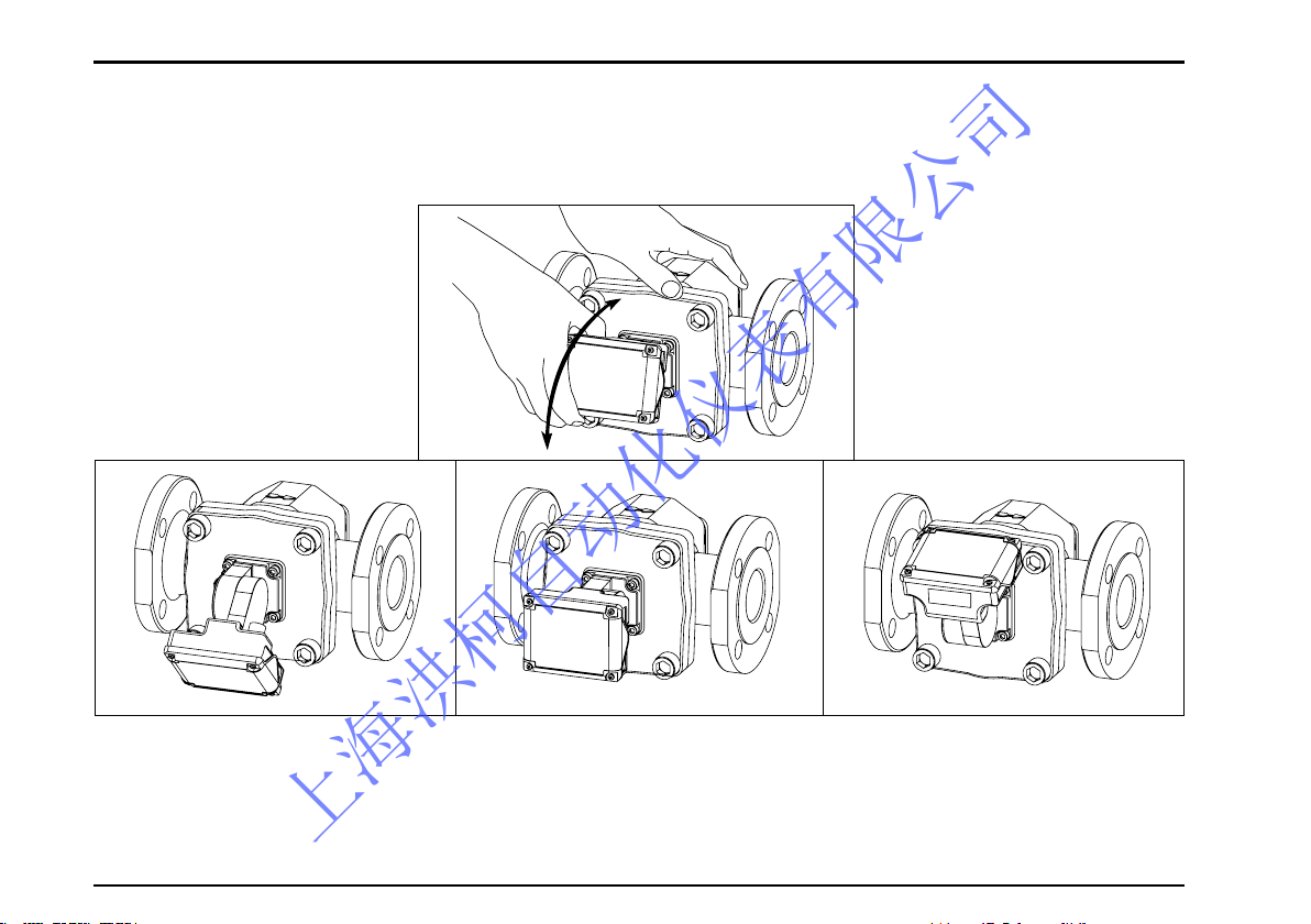
(2) How to change the register orientation
The register display can be easily adjusted by click stop in 15 deg. increment to a desired direction for
maximum viewability. The adjustable range is 150 deg. upward or downward. See the sketches below.
〈Tilted Downward (or Upward)〉 〈Facing Forward (Horizontal)〉 〈Facing Upward (or Downward)〉
上海洪柯自动化仪表有限公司
S-179-1-E
17
Attached cable 1 meter long
5. WIRING
In case of external output capability equipped models LS□□7 -5 , make electrical connections as follows.
Also refer to the instruction manual for the receiving instrument (topic under“Wiring Instructions”) to be used.
5.1 Field wiring
(1) This flowmeter is furnished with 1 meter long cable (vinyl-sheathed, 4-conductor, individual elements
AWG24). To extend the cable, make sure to use shielded cable (CVVS: 1.25 to 2.0mm2) and extend the
shield as well. Leave the extended cable open at its end (no contact).
(2) Transmission length
With transmission cables (CVVS: 1.25 to 2.0mm2), the maximum transmission length is one kilometer. If
using both analog output and pulse output, the transmission distance is 100m max.
NOTE: If transmission length exceeds one kilometer, consult factory.
(3) Prevention of inductive interference
Route the field wiring sufficiently away from existing power cables or power circuits, if any, to minimize
possible stray current pickup.
6
7
3
5
6
7
Make sure of the validity of flowmeter
(p u l s e g e n e r a t o r ) a n d r e c e i v i n g
instrument combination by referring to
their model number, serial number, etc.
before you make electrical connections.
A
B
C
D
The shields of both cables are connected
Extension cable
Leave the end of shield open.
(Do not connect to the earth ground)
CAUTION
0
1
上海洪柯自动化仪表有限公司

S-179-1-E
1
(NOTE) 1. BROWN is for an external power source to the
register.
2. Stripping the outer insulation from the shielded
cable installed exposes a yellow wire, which
must not be used.
5.2 Furnished Leads from the Meter
In c ase of an output capabi lity equi pped mete r,
a shielded cable 1 meter long is furnished. Make
el ectrical co nnection s b y r eferring to th e w iring
nameplate attached to the register.
Wiring Nameplate
BROWN
SUP. +12 to 50VDC
GREEN
COM. 0V
GREY
SIG.1 Factored pulse
WHITE
SIG.2 Unfactored pulse
〈Wiring Nameplate〉
●
Pulse output type
BROWN
SUP.
GREEN
COM.
GREY
SIG.1 Factored pulse
WHITE
SIG.2 Unfactored pulse
●
Pulse output + Analog output type
+12 to 50VDC
4 to 20mA
Analog output
CABLE 1 METER LONG
上海洪柯自动化仪表有限公司

S-179-1-E
19
● ABOUT EXTERNAL POWER SOURCE
IMPORTANT
(1) The meter with external output capability can operate solely on the built-in battery.
However, by supplying external power to leads BROWN and GREEN, it can work without
consuming the battery. Also, even when the meter is operating on external power, do not
remove the battery. (In case external power is interrupted for some reason, the operation
is automatically switched to the battery drive.)
(2) The shielded cable (1 meter long) attached to the instrument with external output
capability is connected to the flowmeter body within the register. Accordingly, leave the
shield of the cable open on the part of the receiving instrument. (Do not connect the
shield to the earth ground terminal, 0V line of the power source, etc.)
(3) An external power source is necessary for using analog output.
上海洪柯自动化仪表有限公司

S-179-1-E
0
5.3 Hook-up Diagrams
(1) Flowpet-5G Output Circuitry
DC
12 to 50V
GRY SIG.1 : Factored pulse
WHI SIG.2 : Unfactored pulse
GRN COM. : 0V
max.
30V
max.
30V
max.20mA
max.20mA
BRO SUP. : Power +
NOTE: Leave the shielded wire open at its end (no contact). To extend the cable,
make sure to use shielded wire and extend the shield as well.
NOTE: Leave the shielded wire open at its end (no contact). To extend the cable,
make sure to use shielded wire and extend the shield as well.
DC
12 to 50V
GRY SIG.1 : Factored pulse
WHI SIG.2 : Unfactored pulse
GRN COM. : 0V
max.
30V
max.
30V
max.20mA
4to20mAAnalogoutput
max.20mA
BRO SUP. : Power +
Loadresistance:RL
● Pulse output type
● Pulseoutput+Analogoutputtype
上海洪柯自动化仪表有限公司

S-179-1-E
1
1. Both factored pulse output and unfactored pulse output are of open drain output (equivalent of open collector).
Install the load to keep 30VDC max, and 20mA.
2. Operating out of the rating or wiring with wrong polarity may cause damage.
<Reference> When converting open drain pulse (equivalent of open collector) into voltage pulse:
(2) About load resistance of analog output
specification
In the analog 2-wire transmission system, power
source cable is also used for signal wiring. Load
resistance of analog output must be installed on the
+ side of the power. In addition, make sure that load
resistance of the meter and leads are with in the
operating range shown in the right gure.
R
E (≦30V)
max.20mA
(NOTE)
Select the value of load resistance R depending on E so that current
flowing through MOSFET becomes 20mA or less.
FLOWPET
WHI (SIG.2) or
GRY (SIG.1)
GRY (COM.)
Acceptable load resistance range
1900
600
0
12 24 50
Power supply voltage (VDC)
Load resistance RL (Ω)
CAUTION
上海洪柯自动化仪表有限公司

S-179-1-E
Left back: MODE button
Right back: RESET button
PUSH!
Low battery alarm
6 DISPLAY AND CONTROLS
6.1 Display and Operation Buttons
Units of registration
(NOTE) About the Display Units
The units of registration can be changed.
L(std.), kL, m3, g, kg, t, gal, ft3, lb, /h, /min, (normal), none
Any change made to the display unit alone does not affect the process of flowrate calculation.
上海洪柯自动化仪表有限公司

S-179-1-E
6.2 Display Capabilities and Operation
(1) Register
Because the register face can be changed to a desired direction in increments of 15 deg., there is virtually no
limitation in choosing meter installation location. As to how to change the physical orientation, see Section 5.
Built around a microprocessor, The register is capable of various display and pulse and analog signal output.
These functions operate on an internal lithium battery which eliminates the need for any external power source.
(External output is also available on an external power.)
(2) LCD display
The 8-digit LCD digitally displays accumulated total, instantaneous flow rate (hourly and per-minute), and
resettable total count, flow rate unit, instantaneous flow rate indicator, and low battery alarm.
(3) External output signal <MODEL LS□□7 −
>
Generates pulse and analog signals for remote flow measurement. See Section 5 for field wiring.
Factored pulse (SIG1) → for flow totalization
Unfactored pulse (SIG2) → for flowrate indication
and recording
Analog output → for instantaneous flow rate
monitoring
(4) Reset pushbutton
Only in the reset total “C mode”,
total count is resettable.
6
7
535655
57
A
B
C
D
0
1
Battery Icon
・Turns on when the battery is low
to suggest battery replacement
Alarm Icons
•Turns on when instant flow rate meets
alarm conditions (optional)
Information Icon
•Turns on when the current mode is
different from the normal measurement mode (such as parameter
review mode)
Flow Rate Display (8-digit)
4 types of display available:
(1) Accumulated total
(2) Instantaneous flow rate (/h)
(3) Instantaneous flow rate
(/minute)
(4) Resettable total
Flow Rate Unit Display
Flow Indicator (10-segment)
•Bar length changes according
to instantaneous flow rate (%)
上海洪柯自动化仪表有限公司

S-179-1-E
(5) Mode selector pushbutton
Each time the “MODE” pushbutton is depressed, accumulated total, instantaneous flowrate (hourly and
per-minute) and resettable total are displayed sequentially.
(NOTE)
1. Depressing the MODE button to obtain an instantaneous
ow rate while the meter is in operation, the internal
counter keeps counting the ow for accumulated total.
2. At very small ow rate below meter's minimum ow rate,
the instantaneous ow rate display remains “0”.
However, totalizing continues to count.
3. Instantaneous ow rate reading may vary depending on
operating conditions and other contributing factors.
4. The display screen scrolls when the MODE button is
released. Holding the MODE button down for more than
5 seconds will make a transition to parameter review
mode.
5. In this instruction manual, “turned ON” refers to the state
where a nger holds the button depressed.
Accumulated total
Instant ow rate: L/h
Instant ow rate: L/m
Resettable total
On the resettable total display,
ze ro- r ese t wi l l be perfor med
on t ota l f low by pr essin g t he
RESET button.
上海洪柯自动化仪表有限公司

S-179-1-E
Indicates that button is tumed “ON.”
①
Ordinary operation
When MODE button is pressed, 8 bars appear.
(NOTE)
In the mode validating “RESET” button operation
(resettable total mode, etc.), the same messages as
above also appear in response to “RESET” button
depression . (In this m ode, however, there is no
distinction between normal depression and prolonged
depression.)
⇒ Immediately turning “OFF” scrolls the window to the
next one.
⇒ By holding MODE button down until the last dash disappears,
“prolonged operation” process (※) takes place. (Releasing
MODE button before the last dash disappears results in the
same behavior as in ① to take place.)
※ prolonged operation: Ope rat ion required for Normal
mode ⇔ Parameter review mode selection, finalizing the
parameter setting, etc.
②
Prolonged operation
Held depressed ON without turning “OFF” immediately.
⇒
Bars begin to disappear from the leftmost one.
Indicates a countdown before “prolonged depression”
processing takes place.
Indicates the countdown before “prolonged depression”
processing takes place.
(7) Flow Indicator Display
Using full scale ow rate setting (parameter: AF) as 100%,
instantaneous ow rate is indicated in 10 segments.
(The maximum ow rate of standard specication is set at
the time of shipment,)
(6) About the Displayed Messages during Operation
上海洪柯自动化仪表有限公司

S-179-1-E
7. OPERATION
7.1 Operation
(1) Read the information given on the nameplate before commencing operation and make sure to see the
operating conditions conform to the specifications. Also make certain that meter installation, pipeline
connections and electrical wiring have been made correctly.
(2) Carefully follow the valve operations sequence given below. On a new installation, care should be exercised
to prevent the rotors from spinning violently by compressed air. (See next page.)
① Close the valve A upstream of and the valve B downstream of the meter.
② Slowly open the valve C on the bypass line to allow the liquid to run through the bypass line, washing
away weld chips, scales or other foreign matter inside the pipeline.
On a newly installed piping assembly, extra care should be used. See Section 4.2 for flushing instructions.
③ Sightly open the valves A and B. Slightly close the valve C if necessary. Make sure to see the counter of
the register slightly moves in response at this time.
④ After a warmup period, slowly close the valve C and progressively open the valves A and B until the
rated flow is reached.
⑤ Flowrate is adjustable with the valve B downstream of the meter. Use the meter within the flow range
specified.
CAUTION 1. In case where the meter is used with heavy oil exceeding 80℃ in
temperature, maintain this condition at least for 10 minutes to obtain
uniform temperature distribution in the measuring chamber.
2.
If you plan to use the water service FLOWPET for boiler feed water, keep the
concentration of antiscale/corrosion inhibitor and deoxidizing agent
according to their instruction manuals. Exceeding their prescribed
concentration may lead to corrosion of the meter and other problems.
上海洪柯自动化仪表有限公司

S-179-1-E
7
LOW DIRECTION
STRAINER
BYPASS LINE
VALVE METER
AB
C
(3) In applications where materials that tend to solidify are to be metered, lagging work is necessary.
See Section 4.3 for lagging work.
(4) The strainer net should be inspected and cleaned on a regular basis. On a newly installed piping assembly
in particular, daily inspection of the net for condition is necessary, stretching the inspection intervals
progressively to once in two or three days down according to the result of inspection.
(5) In case of freezing risk while pausing the operation or intending shutdown for a long period of time:
Remove the drain plug of piping assembly and let the water in the meter and piping assembly out. Water
remaining in the pockets in the meter may not be drained completely. So disassembling the meter for
complete drainage is recommended. (See Section 9 for disassembly procedure.)
FLOW
CONTROL VALVE
Valve operation shown in the sketch will cause violent spinning of
meter rotors which may ruin your meter. Use both hands for caraful
valve operation.
CAUTION
上海洪柯自动化仪表有限公司

S-179-1-E
7.2 About Register’s Life
Due to the life expectancy of electronic components, such as LCD device, and nonvolatile memory,
the electronics in the register requires replacement as an assembly every 10 years approx. The life of
electronics may possibly be more or less reduced, depending on the given environment in which the register
is placed. If the environment comes under any of the following conditions, we suggest you to replace the
register assembly in five or six years:
◎ High temperature environment.
◎ Adverse environment with widely varying temperature.
7.3 Battery Life
(1) The lithium battery incorporated in the register is good for approximately eight years (it may be reduced
more or less depending on the operating and environmental conditions). Operation on external power
source is recommended for the pulse output models. (Supplying external power source will save the battery.)
(2) When the battery has run down, the low alarm icon “ ”
begins to flicker on the display. This blinking icon tells you to
replace the battery unit within a week. (See section 11.1 (4) for
battery replacement.)
(3) Storage life of the battery is 10 years approx after shipment.
Normally, even in an application where the register is powered by an external source and the battery
appears virtually free from any current drain, the storage life requires replacement in ten years approx.
(Taking the abovementioned life expectancy of the register, replacing the entire register assembly will
thus be required.) The battery may possibly have even a shorter storage life under any of the following
environments, requiring
early replacement:
◎ High temperature environment
◎ High temperature fluid measurement
◎ Cold region
上海洪柯自动化仪表有限公司

S-179-1-E
9
8. TROUBLESHOOTING
Symptom Possible Cause Remedy
1. Fluid will not flow.
1. Pipes are connected without removing protective covers
over the inlet and outlet of flanges of the meter.
1. Remove the meter and remove the covers.
2. Oval rotors are jammed with scales and fail to rotate,
blocking the fluid flow.
2. Separate the register, disassemble and clean the meter
body.
3. Pump pressure or head pressure is low.
3. Taking pressure loss of the entire piping system
into consideration, choose a pump that best suits your
application. (See Section 4. PIPING)
2. LCD counter (b1, b2 modes)
fails to count.
1. Flowrate is low. 1. Carefully open the valve.
2. Fluid not owing. 2. Refer to Symptom 1.
3. Steady-ON
“ ”on the LCD.
1. Battery voltage has dropped.
1. Replace the flowmeter, the counter unit or battery unit
within a week.
4. Liquid leaks. 1. Sealed improperly.
1. Retighten pipe connections.
2. Replace the O-ring on meter body cover.
5. Liquid flows but the register
fails to count
1. Rotors are installed backwards.
1. Disassemble the meter body and reinstall the rotors so
that the magnets on the rotor will face the meter body
cover.
6. Counts while valves remain
closed
(without fluid flow).
1. Liquid leaks. Or air pockets between the valve and meter:
rotors oscillate relative to ripple pressures of the pump.
1. Provide an air bleed.
2. Provide a check valve and accumulator.
7. Accumulated total high.
1. Rotors in rocking motion in response to a pulsating flow. 1. Add a check valve and accumulator.
2. Influenced by external magnetic fields (Meter sensor
senses external magnetic fields created by a motor,
generator, etc.).
2. Remove external magnetic fields.
3. Air entrapment. 3. Provide an air vent.
8. Accumulated total low. 1. Influenced by external magnetic fields. 1. Remove external magnetic fields.
●
NOTE:
When troubles is found other than any of those shown above, seek our service. In this case, please supply the
product name, model number, symptoms or other information that will help distinguish the trouble.
上海洪柯自动化仪表有限公司

S-179-1-E
0
■ About Error messages
In cases of improper situations, the 5G register displays error messages on the LCD as follows:
Display Name Description Remedy
PA. Err. Parameter setup error
Rewriting a parameter is attempted although the parameter
is write- protecte d. (In standar d model, pa rameter writeprotect function is turned OFF; it will not be shown.)
Setting No.1 of SW3 of the display board
OF F can cel s thi s con d iti o n ( r ewri t ing
parameters is enabled).
PA. Err. 1 Parameter error 1 Parameter backup data has been lost.
Parameters must be reset after initializing
the CPU.
(Please contact the nearest sales ofce)
PA. Err. 2 Parameter error 2
Display modes, accumulated total flow, or resettable total
ow variable has been lost.
Pressing the MODE button restores th e
normal measurement mode, but variables
of accumulated total flow and resettable
total will be reset.
PA. Err. 3 Parameter error 3 Parameter data for factory reset has been lost.
Pressing the MODE button restores th e
normal measur ement mode , but factory
reset function will remain disabled.
PA. Err. Pu Pulse weight error
Relative to meter factor F and conversion factor H, pulse
weight "Pu" setting is too small.
Adjust settings so that F, H, and Pu satisfy
the following relations:
F×H/2 ≦ Pu ≦ F×H×10000
Out. Err Pulse output error
For one of the following two reasons, pulse OFF
width of factored pulse output falls short of 1msec.
①
Flow rate is too high
②
Factored pulse width setting is too large
In case ①: Reduce the ow rate.
In case ②: Adjust factored pulse width Pon
to an appropriate value according to the
owmeter specication.
FS. Err Full scale error
For one of the following two reasons, measured ow rate is
more than 1.2 times the full scale setting.
①
Flow rate is too high
②
Full scale setting is too small
In case ①: Reduce the ow rate.
In case ②: Adjust full scale setting to an
ap p r o p ri a t e v a l u e a c c o rd i n g t o th e
owmeter specication.
(Battery icon blinking)
Low battery life Circuit voltage is decreasing.
Replace the battery. (If replacing the battery
does not clear this condition, internal failure
is suspected.)
上海洪柯自动化仪表有限公司

S-179-1-E
1
■ Internal switches and test electrodes
With the test electrodes (TP0 through TP4) inside the register, signal waveshape and internal voltage can be monitored.
●
Internal PCB (FB board)
NOTE
1. Description and handling of the waveshape monitoring test electrodes TP1 and TP2 are the same as the previous EG
register. (TP3 [waveshape past the doubler] is not equipped on 5G register, however.)
2. SW3 is for factory setting and does not require further adjustment. All settings are placed in OFF at the time of
shipment.
TP0
SW3
TP4
TP2
TP1
Label Name Description
TP0 (0V)
Test electrode for monitoring
reference potential (0V)
Reference potential (0V) for
monitoring waveshape and
circuit voltage
TP1 (FWD)
Test electrode to monitor
amplied signal waveshape
For monitoring amplied
magnetic sensor signal
waveshape
TP2 (TRG)
Test electrode to monitor
triggered signal waveshape
For monitoring triggered
waveshape (rectangular
wave) of signal at TP1
TP4 (4V)
Test electrode for internal
voltage 4V
For testing internal circuit
voltage (4V)
* Output 4V while external
power is supplied, output
0V when running by battery
power.
上海洪柯自动化仪表有限公司

S-179-1-E
9. DISASSEMBLY AND INSPECTION
(1) Take off four hex bolts of the meter and separate
the register from the meter body.
(2) Holding the register and front cover, separate
horizontally. Inspect the measuring chamber and
remove scales on individual parts. Exercise extra
care not to drop the rotors or they will be damaged.
●
MODEL LS4976, LS5076
◎
Althrough it depends on individual operating conditions, periodic disassembly and inspection every year is
recommended.
〈Meter Body Disassembly and Inspection〉
REGISTER
O-RING
1ST ROTOR
FRONT
COVER
2ND ROTOR
上海洪柯自动化仪表有限公司

S-179-1-E
●
MODEL LS5276, LS5376, LS5576, LS5676, LS5277, LS5377, LS5577, LS5677
(1) Take off four hex bolts of the meter and separate
the register from the meter body.
In case of LS55 □□ and LS56 □□ ,
threading two bolts into the jack screw holes provided
(marked※) in the front cover will facilitate removal.
FRONT COVER
O-RING
(2) Holding the register and front cover, separate
horizontally. Inspect the measuring chamber and
remove scales on individual parts. Exercise extra
care not to drop the rotors or they will be damaged.
《LS5276, LS5376, LS5277, LS5377》
O-RING
《LS5576, LS5676, LS5577, LS5677》
※
Before disassembly,
mark match marks
with felt-tip pen.
REGISTER
FRONT COVER
REGISTER
上海洪柯自动化仪表有限公司

S-179-1-E
1ST ROTOR
MAGNET
N Pole
2ND ROTOR
〈LS4976, LS5076〉
MAGNET
N Pole
ROTOR
〈LS5276, LS5376, LS5576, LS5676〉
〈LS5377, LS5577, LS5677〉
—
Precautions at Assembly
—
Assembly is the reverse order of disassembly. Observe the following instructions:
(1) Assemble the rotors as shown in the sketch. Hand rotate more than one
complete rotation to make sure of freely rotor rotation before installation.
(2) Although identifying the 1st rotor from the 2nd is not required except for
LS4976, LS5076 magnet polarities differ. Be careful to avoid confusion with
other products. When replacing rotors, replace them as a matched pair.Only
in the LS4976, LS5076 the 1st rotor has magnets (two embedded). Installing
the 1st
and 2nd rotors the other way do not affect functions by any means.Install the
rotors so that the magnets on the rotor will face the meter body cover.
(3)
Before installing O-rings, ensure that they are free from damage or
other
unusual condition and exercise care to avoid being caught in the front
cover.
(4) At assembly, use care to keep dust and grime out of the measuring
chamber, which may cause failure, immovable rotors, or other faulty
condition.
(5) Do not attempt to spin the rotors at great speeds by directing an air gun, etc.
〈
CAUTION
〉
1. Score marks, scratches, high spots due to impressions, or other flaws
should be reconditioned flat with oil stone or other tool.
2. If the areas which have been in contact with front cover jack screws are
distorted outwardly, recondition it flat with oil stone.
MAGNET
S Pole
MAGNET
S Pole
ROTOR
上海洪柯自动化仪表有限公司

S-179-1-E
10.EXPRODED VIEW AND SERVICE PARTS LIST
(1) Exploded View
1ST ROTOR (w/magnets)
2ND ROTOR
10
6
7-1
7-2
MODEL : LS4976-5
□□
LS5076-5
□□
LS5276-5
□□
LS5376-5
□□
C
D
C
D
C
D
C
D
High temp. model
MODEL
:LS4976
LS5076
9
8
上海洪柯自动化仪表有限公司

S-179-1-E
●
How to order Flowpet replacement parts
(1) Specify by assembly name. When ordering replacement parts, specify
the model number , instruction manual No.,
assembly name and the quantity desired.
(2) When ordering the register, inform us the parameters indicated (shown
in the sketch at right) along with the information (1) above.
(2) Service Parts List
NOTE ※ : Only in LS4976, LS5076 magnets are embedded in the 1ST rotor.
No. Assembly Name Part Name Quantity Remarks
1 Basic Unit
Basic Unit
1set
Rotor Shaft
2 Front Cover Front Cover 1
3 Rotors
1st Rotor
1set with magnet ※
2nd Rotor
4 Bolts Hex Bolt, Front Cover 4
5 O-Ring O-Ring 1
6 Gasket, Register 1
7-1 Cooling Block 1
7-2 Iron Slag 1
8 Register 1set with battery pack
9 Register with external output
Please inform digits ⑥ , ⑦ ,
and ⑧ (representing register
and output specification) of the
product code.
1set with battery pack
10
Battery pack 1set
Nameplate
上海洪柯自动化仪表有限公司

S-179-1-E
7
11. BATTERY REPLACEMENT AND PARAMETER SETTING PROCEDURE
11.1 Battery Replacement
(1)
The lithium battery incorporated in the register is good for approximately eight years. (The battery life may be
reduced more or less depending on the environmental conditions and other factors.)
(2)
When the battery has run down, the low alarm icon “ ” begins to flicker on the display.
This blinking icon tells you to replace the battery unit within a week.
(3)
This battery is a dedicated battery pack with a connector. Other commercially available batteries cannot be
used. Be sure to use the battery pack dedicated to this register.
上海洪柯自动化仪表有限公司

S-179-1-E
(4)
Battery pack replacement
① If using e xternal power sour ce, d isconne ct
the power first. Take off the four cross recess
screws holding the register housing. Remove
the cover to access the internal PC board. Next,
hold both sides of the LCD and lift the internal
PC board. The battery pack is now accessible.
② Pull out the battery pack and uncouple the
connector from the internal PC board by holding
th e lead wires close t o the connector a n d
pulling it vertically up.
See next page
BATTERY PACK
Over a long period of time, the rubber switches may adhere to the PC
board. Use caution when lifting the PC board. If the rubber switches come
off the housing, place the rubber switches back (at the dents on the sides
of housing interior) then resume the procedure for battery replacement.
CAUTION
RUBBER SWITCH
RUBBER SWITCH
上海洪柯自动化仪表有限公司

S-179-1-E
9
③ Install a new battery pack in place: install it with its red wire lead on the “+”polarity side.
Then carefully place the PC board back into its original position without jamming the lead wires between the
housing and the PC board, and install the cover.
④ When installing register housing tighten four cross-recess screws to the specification below: (Allowable
tightening torque: 0.4[N • m])
●
Replacement battery packs are available at
your nearest sales office.
BATTERY PACK
When you separate the register housing, be extremely careful to keep moisture
and dust out. Also, keep your fingers off the electronics.
〈
CAUTION
〉
上海洪柯自动化仪表有限公司

S-179-1-E
0
11.2 Parameter Setting Procedure
If you want to rewrite some parameters of the register, such as the unit of accumulated total, it is necessary
that the parameters stored in the CPU be rewritten. If such is the case, rewrite parameters by the following
procedure.
(1) Parameter Setting
In cases where replacing the entire register assembly is required, or restoring the factory established
parameter settings is desired, refer to the parameter list.
Unfactored pulse unit and factored pulse unit are stated in the nameplate (see below).
Unfactored pulse unit (Meter factor)
Factored pulse unit (Pulse weight)
Nameplate
上海洪柯自动化仪表有限公司

S-179-1-E
1
• Total ow related data (Title Display: totAL)
Symbol Parameter Description Remarks
F Meter factor Meter factor of the owmeter (Unit: L/Pulse)
Example: Given meter factor 9.918mL/P (= 9.918 × 10⁻³ [L/P])
→
Set to "F9.9180 − 3" (L/P).
H Conversion factor Unit conversion factor (Unit:[Converted Unit/L])
To convert total ow and instant. ow rate units to units other than L.
(Normally H1.0000E0 unless unit conversion takes place.)
Example: at 1.5kg per 1L, to convert the ow rate to read in kg
→
Conversion factor is 1.5 [kg/L] (=1.5000 × 1000[kg/L]); Set to "H1.5000E0" [kg/L]. (Note 1)
Pu Pulse weight Pulse weight of factored pulse output (Unit:[L/P])
Example: To change factored pulse weight to 10L/P (=1.00 × 10+1 [L/P])
→
Set to "Pu 1.00E1" (L/P). (Note 2)
Pon Pulse width ON width of factored pulse (Unit:[msec]) Example: To obtain factored pulse width of 100ms → Set to "Pon 100" (ms). (Note 3)
Un Indicated unit Description of unit display on the bottom of the LCD
By changing Un, units that appear on LCD can be changed.
(This is a change in indicated units; it does not affect ow calculation.)
Setting items: L, kL, m3 , gal, ft3 , g, kg, t, lb, none
SP Total ow decimal point Decimal point of accumulated total and resettable ow Example: To show total ow to 0.01L (= two places below decimal point) → Set to "SP .2".
d.o1 Digital output assign. 1 Output spec. of SIG1 (Color: GRY)
Setting items: U.PLS: Unfactored pulse, PLS: Factored pulse,
AL.1: Alarm 1, AL.2: Alarm 2, -: No assignment (Alarm capability is optional.)
d.o2 Digital output assign. 2 Output spec. of SIG2 (Color: WHI)
(2) Parameter List (1/2)
(NOTE: Flow unit “L” written under “Description” in the following table refers to the standard setting.)
• Instantaneous ow related data (Title Display:rAtE)
Symbol Parameter Description Remarks
AF Full scale ow rate
Full scale ow rate for ow indicator and analog output
(Unit: L/h)
Example: To set full scale ow rate of analog output to 1800L/h (= ow rate that is represented
by 20mA) → Set to "AF 1800" (L/h) Note that the place of decimal point depends on bP.
AdAn Damping
Time constant for instantaneous ow rate value
(Unit: [sec])
In case ripple of instant. ow rate display and analog output is too great, setting larger value
for AdAn will stable the indication. Example: To set time constant of instantaneous ow rate
display and analog output at [5sec] → Set to "AdAn 5.0".
bP Instant ow decimal point
Decimal point place of per-hour instantaneous ow rate:
b1 measurement
Example: To show instantaneous ow rate to 0.1 L/h (= one place below decimal point)
→
Set to "bP .1". Per-minute instant. ow rate: b2 is bP+2 digits
At Sampling time
Timeout duration in instantaneous ow rate
measurement (Unit: [sec])
If no ow rate pulse arrives during At [sec], instantaneous ow rate is 0.
A Sampling cycle number
Number of sampling cycles in instantaneous ow rate
measurement
Instantaneous ow rate is determined by timing the incoming ow rate pulses for A times. If
dispersion in instant. ow rate indicated is too great, choosing a greater A eases the problem.
(NOTES) 1: In case of changing conversion factor (H), related parameters such as pulse weight (Pu) and indicated unit (Un) must also be changed according to the converted unit.
F×H
2: Make sure that the setting satises ≦Pu≦F×H×10000.
2
3: Be sure to set up a value such that factored pulse "OFF" duration > 1 ms.
上海洪柯自动化仪表有限公司

S-179-1-E
Symbol Parameter Description Remarks
A1d Alarm 1 Setting Instantaneous ow rate value that triggers Alarm 1 (Unit:L/h) (Decimal point depends on bP)
A1H Alarm 1 Hysteresis Alarm 1 Hysteresis setting (Unit:L/h) (Decimal point depends on bP)
A1S Alarm 1 Status Status setting of Alarm 1
【
Left digit of the setting】L: Low Alarm, H: High Alarm
【
Right digit of the setting】S: Transistor ON during Alarm, O: Transistor OFF during Alarm
A2d Alarm 2 Setting Instantaneous ow rate value that triggers Alarm 2 (Unit:L/h) (Decimal point depends on bP)
A2H Alarm 2 Hysteresis Alarm 2 Hysteresis setting (Unit:L/h) (Decimal point depends on bP)
A2S Alarm 2 Status Status setting of Alarm 2
【
Left digit of the setting】L: Low Alarm, H: High Alarm
【
Right digit of the setting】S: Transistor ON during Alarm, O: Transistor OFF during Alarm
■
Parameter List (2/2)
(NOTE: Flow unit “L” written under “Description” in the following table refers to the standard setting.)
• Alarm data (Title Display: AL) NOTE: Not displayed on standard specification. (Displayed only on alarm option specified models) See (8) of this
section for operation detail.
Symbol Parameter Description Remarks
I.Fr Input frequency display Displays frequency of ow signal detected (Unit: Hz)
These parameters are for conrming the state of device
and not for setting.
O.t Operating time Accumulated operating time since the time of shipment (Unit: time)
F.t Flow operating time Accumulated ow operating time since the time of shipment (Unit: time)
SWM No. of times MODE button is pressed Shows how many times MODE button has been pressed (Unit: number of times)
SWR No. of times RESET button is pressed Shows how many times MODE button has been pressed (Unit: number of times)
th LPF determining threshold Threshold for determining low-pass lter (Normally disabled=set at “00”)
Should not be used under normal circumstances P.Fr. LPF frequency Low-pass lter setting (displayed only when tH is other than 00)
FC.r Factory reset Reset all parameters to the factory setting value
SoFt. Software revision For factory use
This parameter is for conrming the state of device and not for setting.
• Service mode (Title Display:88888888) NOTE: These parameters are for use by OVAL service personnel.
Symbol Parameter Description Remarks
A04 Analog Output 4mA trim Analog 4mA output calibration mode (Unit:mA)
Calibrated at the time of shipment. Normally unused.
A20 Analog Output 20mA trim Analog 20mA output calibration mode (Unit:mA)
• Analog trim (Title Display: AnA.tri.) NOTE: Displayed only on meters with analog output capability. See (6) of this section for operation detail.
Symbol Parameter Description Remarks
S.b Simulated instantaneous ow rate Set the value of instantaneous ow rate for simulated output
Set these parameters when performing loop test and etc. S.c Simulated total ow Set the value of total ow rate for simulated output
Start Simulated output Execute simulated output based on the conditions set for parameters S.b and S.c
• Simulated output (Title Display: LooPtESt) ※See (7) of this section for operation detail.
上海洪柯自动化仪表有限公司

S-179-1-E
(3) Parameter Setup Procedure
With MODE and RESET buttons in the display, you can set up parameters.
A diagram to show parameter setup flow
Measure Mode
(normal mode)
Review Mode
Parameter
Setup Mode
2 3
4
56
7
1
● Given below is the parameter setup procedure:
①In "Measure Mode (normal mode)," hold MODE button depressed
for more than 5 seconds to go into "Review Mode."
⑦Hold MODE button depressed for more than 5 seconds to
go back to "Measure Mode."
⑥Using MODE and RESET buttons,
(= totAL, rAtE, AL ※1), AnA. tri. (※2), LooPtESt, 88888888)
(※1) AL: Only with alarm option
(※2) AnA.tri.: Only for analog output equipped model
⑤Following the parameter entry, hold MODE button depressed
for more than 2 seconds to go back to "Review Mode."
④Using MODE and RESET buttons, set up the new parameter.
(For details of this operation, see (5) )
③Hold MODE button depressed for more than 2 seconds to go
into "Parameter Setup Mode."
②Using MODE and RESET buttons, show the paramete your
want to modify.
NOTES:
1. For details of button opera-
tion in steps ① , ② , ③ , ⑥ ,
and ⑦ , see (4) Menu Trees
and Button Operation.
2. Throughout the text in this
instruction manual, holding
the MO D E and R E S E T
b u t t o n s de p r e s s e d is
expressed as“turned ON”.
上海洪柯自动化仪表有限公司

S-179-1-E
(4) Menu Trees and Button Operation
NOTE: Goes back to the screen before
switching to Review Mode
Transition made by pressing "MODE" button
Transition made by keeping "MODE" button pressed for more than 5 seconds
Transition made by pressing "RESET" button
Measure Mode (normal mode)Review Mode
※ 1
None
1
2
C
Accumulated total
Instant flow rate (hourly)
Instant flow rate (per-minute)
Resettable total
Total flow related data
Instant flow related data
Alarm data
Alarm 1 setting
Alarm 1 hysteresis
Analog trim
4mA trim
20mA trim
Alarm 1 status
Simulated output
Instant flow setting
Total flow setting
Simulated output
Service mode
Input frequency display
Operating time
Flow operating time
No. of MODE button press
No. of RESET button press
LPF determining threshold
LPF frequency
Factory reset
Software revision
Alarm 2 setting
Alarm 2 hysteresis
NOTE: Not displayed on standard specification.
(Displayed only on alarm option specified models)
NOTE: Displayed only on analog output
equipped models.
Alarm 2 status
Full scale flow rate
Instant flow decimal point
Damping
Sampling time
Sampling cycle number
Conversion factor
Pulse weight
Pulse width
Indicated unit
Total flow decimal point
Digital output assign. 1
Digital output assign. 2
Meter factor
※1: During Review Mode, the information icon is
displayed on the upper right corner of the screen.
※2: Parameter symbols are displayed at flow rate unit
display area.
※3: Displayed only when a value other than "00" is set
for the parameter: tH.
: Holding the MODE button pressed for more than 2 seconds at this display
changes the Review Mode to the Write Mode. The following operations are
enabled in the Write Mode:
①Pressing the MODE button moves the digit one place to the left.
②Pressing the RESET button increases the figure by one.
③Holding the MODE button pressed for more than 2 seconds again changes
the mode back to the Review Mode.
: Title
(Titles describe the attributes of each parameter stored under each title:
They are not settable parameters.)
: Switching to Write Mode from these displays will allow operators to use
special functions such as analog trims and simulated output.
上海洪柯自动化仪表有限公司

S-179-1-E
(5) The procedure to manually enter a parameter
Switch operations sequence in "Parameter Setup Mode" comes in three ways (numerical setup, units
setup, and decimal point setup) that follow:
① Numerical setup parameters (F, H, Pu, Pon, Af, AdAan, At,
A, A1d, A1H, A2d, A2H)
The blinking digit in the parameter setup mode is the place
of interest.
MODE
…Each time the button is turned ON, the blinking
place moves one place to the left.
RESET
…Each time the button is turned ON, the figure in
the blinking place increases by one.
Or exponential sign toggles ("E"
←→ "-").
→
Following the parameter setup, hold the "MODE" button
depressed for 2 seconds (the new setting is established
and the screen returns to the review mode).
②
Decimal point setup parameter (bP and SP)
In the parameter setup mode, a gure representing the
decimal places of interest ickers.
MODE
…
Not used in the setup process
RESET
…
Each time the RESET is pressed, the decimal
point moves one place to the left and the gure
increases by one.
→
When the decimal point appears at the desired location,
hold the MODE button depressed for 2 seconds (the new
setting is established and the screen returns to the review
mode).
Example: Parameter: F (meter factor)
Example: Parameter: bP (instant. ow decimal point)
Digit to be set (blinking)
• Press MODE to move the blinking digit one place to the left ("E")
• Press RESET to increase the numerical value by one ("2" → "3")
Number of decimals (blinking)
Decimal point (place
varies with the value on
the right)
• Press RESET to increase the numerical value by one ("1" → "2")
and move the decimal point one place to the left
Exponent sign (E: 10+n, ー: 10-n)
(The display below represents: F= 1.2345 × 10²)
上海洪柯自动化仪表有限公司

S-179-1-E
③
Item selection parameters (Un, d.o1, d.o2, A1S, A2S)
In the parameter setup mode, the ickering part of a display indicates an item subject to change.
MODE
…
Each time MODE is pressed, the decimal point moves one place to the left (applicable only to A1S
and A2S).
RESET
…
Each time the RESET is pressed, the displayed item changes to the next available item.
→
When the desired item for the parameter is displayed, hold the MODE button depressed for 2 seconds
(the new setting is established and the screen returns to the review mode).
Available option for
digital output 1 (blinking)
Example: Parameter: Un (indicated unit) Example: Parameter: d.o1 (digital output 1)
Display unit (blinking)
• Each time RESET is pressed, the displayed item
changes to the next available item such as:
[L→kL→m3→gal→ft3→g→kg→t→lb→none]
• Each time RESET is pressed, the displayed item
changes to the next available item such as:
[U.PLS→PLS→AL.1→AL.2→ no output (display: ----)]
上海洪柯自动化仪表有限公司

S-179-1-E
7
(6) Analog output trim procedure
Analog output trimming (calibration of analog output characteristics) is performed at the
time of shipment; there is no need to perform this procedure under normal circumstances.
→
+
DC Power
-
○
A
Ammeter
【STEP4】Confirmtrimmed4mAoutput
Example: 4mA trim procedure
【STEP3】Entersimulatedoutputcurrentvalue
【STEP2】Begin4mAsimulatedoutput
【STEP1】Preparation
①Setupanammeter(orvoltmeter)tomonitoranalogoutput.
20mA output trim can be performed by the same procedure described above in 20mA trimming mode (A20).
①Press MODE button for 2 seconds while
[A04 4.000] is displayed
→The setting (far-right "0") starts blinking and
4mA simulated output begins.
②Once output becomes stable, read the ammeter
value.
①Enter the ammeter reading by following the
same procedure as parameter setting.
→For example, if the ammeter reads 3.988mA,
enter "3.988" as shown above.
②Establish the setting by pressing MODE button
for 2 seconds.
→Analog output is trimmed towards 4.000mA
according to the setting.
①Check the ammeter reading once again.
(At this point, the display is back to [A04 4.000]
with the far-right digit blinking)
②If the reading is acceptable for 4.000mA, press
MODE button for 2 seconds to exit set ting mode
→Trimming complete (⇒If the reading remains
unacceptable, perform trimming again from
procedure ④.)
上海洪柯自动化仪表有限公司

S-179-1-E
(7) Simulated output function (LooPtESt)
In the parameter review mode, simulated output can be performed by specifying "Instantaneous ow rate (S.b)" and "Total ow (S.c)"
then executing "Start".
Simulated output is calculated from parameters such as Meter factor, Pulse weight, Analog full scale, etc., based on "Instantaneous
ow" setting.
Signals subject to simulated output
• SIG.1 and SIG.2: Unfactored pulse, Factored pulse, Alarm 1, or Alarm 2 (depends on d.o1 and d.o2 settings)
• Analog output
(NOTE)
• Simulated output does not affect actual measured values (accumulated total mode and resettable total mode)
• Due to the capability of simulated output (frequency resolution), instantaneous ow rate (S.b) value may automatically changed to
a value available for simulated output that is closest to manually set value.
• Although simulated output function is available while there is actual ow, the actual ow will not be measured by the register.
Example:Simulatedoutputperformedfor1800L/h,100L
【
STEP1】Simulated instant flow rate setting
【
STEP2】Simulated total flow setting
【
STEP3】Begin simulated output
①In the pa ram eter r evie w mode , disp lay
the ite m " S.b" a nd pres s M ODE bu tton
for 2 se conds.
②As t he d ispl ay starts b lin king , en ter
1800 [L/h ] follo wing th e sa me p roc edure as paramet er s ett ing.
③Esta blis h the setting by pres sing
MODE button for 2 second s (blin kin g
stop s).
→Pres s MOD E but ton once and move
to "S.c "
①In th e par ame ter r evi ew mo de, disp lay
the i tem "S.c " and pre ss M ODE b utton
for 2 se conds.
②As t he d ispl ay s tar ts b link ing, en ter
100[ L] using the sam e proc edur e as
para mete r setti ng.
③Esta blis h th e se ttin g by pressin g
MODE but ton for 2 s econ ds (blink ing
stop s).
→Pres s MO DE butt on o nce and mov e
to "StA rt"
↑
Hold down MODE button
①In th e pa rame ter revi ew m ode, dis play the ite m "St Art " and pre ss M ODE
butt on f or 2 se cond s.
②Simu late d to tal flo w se ttin g (100) est abli she d in 【ST EP2】 will be
disp laye d indic atin g t hat it is r eady for si mula ted out put.
③Simu late d output starts by pressi ng RESET button once, and the tota l
coun ts do wn t o zer o (d urin g simula ted o utp ut, " S" o n the left han d
blin ks).
→Pre ssing M ODE but ton onc e durin g simul ated ou tput pa uses th e
pro cess (Press RES ET butt on to r esum e).
④Simu late d outpu t is co mple te when the count reac hes zer o.
・To ru n si mulated out put aga in w ith the sam e s etti ng→conti nue fro m ③
・To fi nish simula ted output proc edu re, pres s M ODE button for 2
se cond s to go bac k to ① ( StAr t)
上海洪柯自动化仪表有限公司

S-179-1-E
9
(8) About alarm output function (optional)
【
Alarm related parameters and their meaning
】
Parameter Symbol Parameter Description
A 1 d
□□□□□
Alarm 1 Setting Alarm ow rate setting for Alarm output 1 (Set as per-hour ow rate)
A 1 H
□□□□□
Alarm 1 Hysteresis
Hysteresis for Alarm output 1 (Set as per-hour ow rate)
Threshold between alarm setting value and the value at which the alarm is
canceled
A 1 S
△○
Alarm 1 Status
Output status of Alarm output 1
△ :
High alarm or Low alarm setting
Set at "H" → High alarm, Set at "L" → Low alarm
○ :
State of external output during alarm (MOSFET/open drain output)
Set at "S"
→
Short (
・・・
contact "Close")
Set at "O"
→
Open (
・・・
contact "Open")
A 2 d
□□□□□
Alarm 2 Setting Alarm ow rate setting for Alarm output 2 (description is same as A1d)
A 2 H
□□□□□
Alarm 2 Hysteresis Hysteresis for Alarm output 2 (description is same as A1h)
A 2 S
△○
Alarm 2 Status Output status of Alarm output 2 (description is same as A1S)
Off
Open Open
Open
Close
Close
Close
Off
Off Off
Instant. flow rate
A2d=1000
A2H=1
A1H=5
A1d=500
ALARM1
ALARM2
icon
icon
Alarm output 1 (open drain)
Alarm output 2 (open drain)
On
On
• When the instantaneous ow rate exceeds (or falls
below) the alarm setting, an ALARM icon will be
turned on and external alarm output signal will be
generated.
• Hysteresis can be set for alarm.
• There are 2 points for alarm: Alarm 1 and Alarm 2.
These can be set individually.
〈
CAUTION
〉
If not intending to use alarm function, "0" must
be set for A1d and A2d.
→
By setting "0" for A1d or A2d, each alarm
function will be disabled.
For example: If A1d=500, A1H=5, A1S=LS, A2d=1000, A2H=10, A2S=HO
上海洪柯自动化仪表有限公司

S-179-1-E
0
12. GENERAL SPECIFICATIONS
(1) Flow Range
Meter Size
Nominal Dia. mm
Water Service
L/h
Oil Service L/h
Water Service Oil Service Kerosene Light Oil (A Heavy Oil) Heavy Oil
49
—
20
—
10 (20) to 800 7 (14) to 800 5 (10) to 800
50
—
20
—
150 (300) to 1600 80 (160) to 2000 50 (100) to 2000
52 20 25 200 to 1200 300 (600) to 3000 150 (300) to 3800 80 (160) to 3800
53 25 40 600 to 3600 600 (1200) to 5000 300 (600) to 6400 150 (300) to 6400
55 40 40 1200 to 7200 1200 to 11000 600 to 14000 400 to 14000
56 50 50 2000 to 12000 2000 to 20000 1400 to 24000 900 to 24000
★
NOTE Kerosene: 0.8 to 2mPa•s, Light Oil: 2 to 5mPa•s, Heavy Oils: 5 to 200mPa•s
Values in parenthesis represent the minimum flow rate of the high temperature model.
(2) Meter Body
Item Specifications
Application fluid Liquid
Application Water service Oil service
Accuracy ±1.0% of RD ±0.5% of RD
Operating Temperature Range (Fluid Temp.) 0 to 120℃ 0 to 120℃ (0 to 150℃)
Max. Operating Pressure 1.18MPa (static running water) 1.18MPa (0.98MPa)
Flange Rating JIS 10K RF JIS 10K RF, ASME 150 RF
Materials
Meter Body Stainless steel Cast iron
Rotors Special resin
Register Housing Polycarbonate resin
Finish
Meter Body Not painted Orange: Munsell 2.5YR6/13
Register Housing Black
( )For high temperature model.
上海洪柯自动化仪表有限公司

S-179-1-E
1
(3) Register, Pulse Generator
Item Description
Display
①
Accumulated total ow (8-digit)
②
Instantaneous ow rate, L/h (mode: b1)
③
Instantaneous ow rate, L/min (mode: b2)
④
Resettable total ow (zero start/zero resettable, mode: C) (7-digit)
Function
①
Low battery alarm (Low battery indicator “ ” ickers below 3.0V)
②
LCD with 7-segment, 14mm-high characters (background color: orange)
③
Flow indicator (10-segment)
④
Simulated output: set any accumulated total or instantaneous ow rate for simulated outputs (unfactored, factored, and analog)
⑤
Protection against erroneous wire connection
Register accuracy Total ow: ±1 count, Instantaneous ow rate: within ±1% of full scale
Display orientation 150° range in 15° steps (From horizontal position: upward 75°, downward 75°)
Flow detection Magnetic sensor detects alternating magnetic elds. Response frequency 200Hz max.
Pulse output
Output type Open drain (equivalent of open collector)
Capacity Allowable current: 20mADC, Max. voltage applied: 30V
Pulse type Factored Unfactored
Pulse width 1ms, 50ms, 100ms, 250ms (※1) 2ms (xed)
Alarm output
(optional)
Output type Open drain (equivalent of open collector)
Capacity Allowable current: 20mADC, Max. voltage applied: 30V
Alarm
output point
Up to 2 points
(“High alarm instant ow rate” or “Low alarm instant ow rate” can be set with any value for each output point)
Analog output 4 to 20mADC (load resistance: see Section 5.3 “acceptable load resistance range”)
Cable
1 meter of vinyl-sheathed, 4-conductor (individual elements 0.25mm2, φ6.3 O.D.) cable furnished (standard)
(Not furnished with models without output capability)
Transmission distance
1 kilometer max. (when CVVS: 1.25 to 2.0mm2 cable is used)
If using both analog output and pulse/alarm output, the transmission distance is 100m max. (when CVVS: 1.25 to 2.0mm2 cable is used)
Power source (※2)
Battery pack or external power source
Battery pack Lithium battery: 3.6VDC 5400mAh Battery life: 8 years (varies with operating conditions) Storage life: 10 years
External
power source
12 to 50VDC±10%
Pulse output : Current capacity 10mA or more
Analog output : Current capacity 30mA or more
Ambient temperature range -10 to +60℃ (no condensing)
Material Polycarbonate (black)
Conguration IP65 (Install under the eaves)
※1: Adjustable with button operation within the range of 1 to 999ms in 1ms increments. Shown above are default settings.
※2: Display functions and pulse output functions can be used just with the dedicated battery pack without an external power source.
(With an external power source, there is no need to worry about the battery life. The power will be automatically switched to battery power in case of power shut-down.)
An external power source is necessary for analog output.
Selectable with MODE button
上海洪柯自动化仪表有限公司

S-179-1-E
(4) Units of Registration, Pulse Output Units of Registration
Application
Model
Nominal
dia., mm
Max. Total
Reading
Factored Output Pulse
Factored Output Pulse Width
○ : Selectable
Unfactored Output Pulse
Pulse Unit Output freq. 1 ms 50 ms 100 ms 250 ms Meter Factor Output Freq.
Water
service
LS5277 20
999999.99 L
10 mL/P 33.3 Hz
○
9.918 mL/P 33.6 Hz9999999.9 L
100 mL/P 3.33 Hz
○ ○ ○
99999999 L
1 L/P 0.33 Hz
○ ○ ○ ○
LS5377 25
9999999.9 L
100 mL/P 10.0 Hz
○ ○
17.955 mL/P 55.7 Hz99999999 L
1 L/P 1.00 Hz
○ ○ ○ ○
99999999 L
10 L/P 0.10 Hz
○ ○ ○ ○
LS5577 40
9999999.9 L
100 mL/P 20.0 Hz
○
35.496 mL/P 56.3 Hz99999999 L
1 L/P 2.00 Hz
○ ○ ○ ○
99999999 L
10 L/P 0.20 Hz
○ ○ ○ ○
LS56277 50
9999999.9 L
100 mL/P 33.3 Hz
○
76.455 mL/P 43.6 Hz99999999 L
1 L/P 3.33 Hz
○ ○ ○
99999999 L
10 L/P 0.33 Hz
○ ○ ○ ○
Oil
service
LS4976 20
999999.99 L
10 mL/P 22.2 Hz
○
5.928 mL/P 37.49 Hz
9999999.9 L
100 mL/P 2.2 Hz
○ ○ ○
99999999 L
1 L/P 0.22 Hz
○ ○ ○ ○
LS5076 20
999999.99 L
10 mL/P 55.5 Hz
○
9.912 mL/P 56.0 Hz9999999.9 L
100 mL/P 5.55 Hz
○ ○ ○
99999999 L
1 L/P 0.55 Hz
○ ○ ○ ○
LS5276 25
999999.99 L
10 mL/P 105 Hz
○
9.639 mL/P 109.5 Hz9999999.9 L
100 mL/P 10.5 Hz
○ ○
99999999 L
1 L/P 1.05 Hz
○ ○ ○ ○
LS5376 40
9999999.9 L
100 mL/P 17.7 Hz
○
17.470 mL/P 101.7 Hz99999999 L
1 L/P 1.77 Hz
○ ○ ○ ○
99999999 L
10 L/P 0.17 Hz
○ ○ ○ ○
LS5576 40
9999999.9 L
100 mL/P 38.8 Hz
○
34.526 mL/P 112.6 Hz99999999 L
1 L/P 3.88 Hz
○ ○ ○
99999999 L
10 L/P 0.38 Hz
○ ○ ○ ○
LS5676 50
9999999.9 L
100 mL/P 66.6 Hz
○
74.483 mL/P 89.5 Hz
99999999 L
1 L/P 6.66 Hz
○ ○ ○
99999999 L
10 L/P 0.66 Hz
○ ○ ○ ○
上海洪柯自动化仪表有限公司

S-179-1-E
(5) Applicable standards
Applicable EU Directive
EMC Directive: 2014/30/EU
RoHS Directive: 2011/65/EU
Applicable EN standards, etc.
EMC Directive: EN61326-1: 2013 Class A
RoHS Directive: EN50581: 2012
(NOTES )
1. Output frequencies are those values at the maximum flowrate.
2.
Hatched areas
show setup options.(Unhatched area: Default at shipment from factory)
3.
Factored pulse output unit (pulse weight) or factored output pulse width marked with ○ in
the table are adjustable. If you want to change the current setting, make sure of the circle
○
first and set up new prameters Pu (pulse weight) or Pon (pulse width) referring to Section 11.2
Parameter Setup Procedure.
4. Factored pulse width is adjustable in increments of 1 ms bcsides those marked with circle
○ ,
however, in this case, use care to avoid bridging of adjacent pulses at max. flowrate.
上海洪柯自动化仪表有限公司

S-179-1-E
13. OUTLINE DIMENSIONS
(1) FLOWPET-5G
Register orientation
adjustable in 15° steps
(75° upward, 75° downward)
External output cable entry
(1m long cable furnished)
(Covered with a blind plug for
models without external output)
75°
75°
RESET
RESET
A
B
82.5
L
H
FLOWPET-
5G
( )For high temperature model. ※: In the case of JIS 10K RF flange.
Dia.,
Model
Nominal
Dia., d
L (※) A B H
Weight
kg
Water
Service
LS5277 20 225 209.5 163.5 96 6.4
LS5377 25 225 234.5 177.5 96 7.9
LS5577 40 245 242.5 184.5 124 9.7
LS5677 50 280 260.5 188.5 146 14.6
Oil
Service
LS4976 20 150 205.5(235.5) 160.5(190.5) 66 3.3 (3.4)
LS5076 20 150 214 (240.5) 169 (195.5) 70 4.3 (4.4)
LS5276 25 225 223.5(248.5) 168.5(193.5) 96 6.3 (6.4)
LS5376 40 225 237.5(262.5) 179.5(204.5) 96 7.8 (7.9)
LS5576 40 230 242.5 184.5 124 9.8
LS5676 50 250 260.5 188.5 146 14.6
Unit in:mm
上海洪柯自动化仪表有限公司

S-179-1-E
(2) Strainer
L
A
Unit in:mm
Model Nominal Dia. L (※) A Weight, kg Net mesh Applicable Flowpet
SS5278A 20 125 82 3.4 80
LS4976, LS5076
LS5277
SS5378A 25 140 104 5.3 60 LS5377, 5276
SS5578A 40 170 129 7.7 60 LS5577, 5376, 5576
SS5678A 50 190 153 9.6 60 LS5677, 5676
※: In the case of JIS 10K RF flange.
上海洪柯自动化仪表有限公司

S-179-1-E
2017.06 Revised
2017.01 Revised
2016.03 Revised
2015.11 Released
S-179-1 -E (4)
All specifications in this instruction manual are subject to change without notice for improvement
in performance and product quality.
上海洪柯自动化仪表有限公司
OVAL总代理: 上海洪柯自动化仪表有限公司
电话: 021-54485672
网址: WWW.SHAKIC.COM
Email: shakic@163.com
 Loading...