

Oval LS5677-5**B Series, LS5377-5**B Series, LS5577-5**B Series, LS4976-5**A Series, LS5277-5**B Series Instruction Manual
...
Ins. No.
S-179-1-E
ELECTRONICS REGISTER PROVIDED
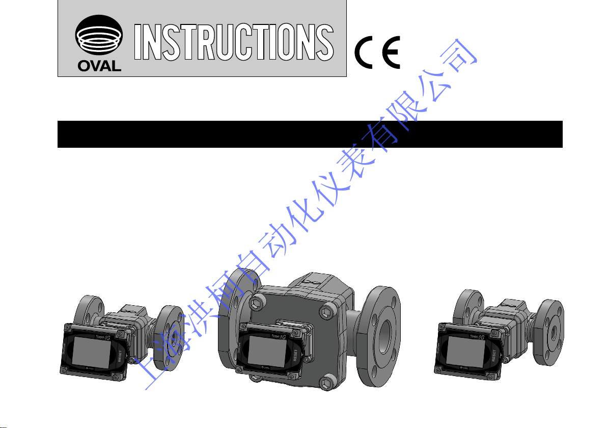
FLOWPET
-5G
Water service
MODEL:LS5277-5 □□B, LS5377-5 □□B, LS5577-5□□B, LS5677-5□□ B
Oil service
MODEL:LS4976-5□ □ , LS5076-5□ □ , LS5276-5□ □ , LS5376-5□ □ , LS5576-5□ □ , LS5676-5□ □
A
B
C
D
A
B
C
D
A
B
C
D
A
B
C
D
A
B
A
B
Ins. No.
S-179-1-E
ELECTRONICS REGISTER PROVIDED
FLOWPET
-5G
Water service
MODEL:LS5277-5 □□B, LS5377-5□□B, LS5577-5□□ B, LS5677-5 □ □B
Oil service
MODEL:LS4976-5□ □ , LS5076-5□ □ , LS5276-5 □ □ , LS5376-5□ □ , LS5576-5 □□ , LS5676-5□ □
A
B
C
D
A
B
C
D
A
B
C
D
A
B
C
D
A
B
A
B
上海洪柯自动化仪表有限公司
OVAL总代理: 上海洪柯自动化仪表有限公司 电话: 021-54485672 网址: WWW.SHAKIC.COM Email: shakic@163.com
S-179-1-E
A great deal of time and care has been devoted to the proper designing, manufacturing and preparation of the
Flowpet-5G for delivery into your hands. We hope that you derive from its operation the full measure of value
and utility to which you looked forward to when you purchased it. Your considerate treatment and care will repay
you well throughout its service life. For these reasons, we suggest you to read this instruction manual
throughly befor use and keep it for your quick reference.
CONTENTS
1. HANDRING PRECAUTIONS ........................................3
1.1 Confirming the Nameplate .......................................3
1.2 Transportation Precautions .......................................4
1.3 Storage Precautions.................................................5
1.4 Installation Location Precautions .............................6
2. OPERATING CONDITIONS ..........................................6
3. GENERAL DESCRIPTION ..........................................7
3.1 Features .................................................................7
3.2 Product Code Explanation .......................................8
3.3 Part Names ..............................................................9
4. PIPING.........................................................................10
4.1 Piping Precautions..................................................10
4.2 Flushing the Piping Assembly................................12
4.3 Lagging Work.........................................................12
4.4 Example of Installations..........................................13
4.5 How to Change the Flow Directions and
Display Orientations................................................15
5. WIRING .......................................................................17
5.1 Field Wiring ............................................................17
5.2 Furnished Leads from the Meter............................18
5.3 Hook-up Diagrams .................................................20
6. DISPLAY AND CONTROLS .......................................22
6.1 Display ...................................................................22
6.2 Display Capabilities and Operation........................23
7. OPERATION..............................................................26
7.1 Operation ..............................................................26
7.2 About Regiater,s Life............................................28
7.3 Battery Life ...........................................................28
8. TROUBLESHOOTING...............................................29
9. DISASSEMBLY AND INSPECTION .........................32
10. EXPLODED VIEW AND SERVICE PARTS LIST .....35
Exploded View.........................................................35
Service Part Lists ....................................................36
11. BATTERY REPLACEMENT AND
PARAMETER SETTING PROCEDURE .................37
11.1 Battery Replacement............................................37
11.2 Parameter Setting Procedure ..............................40
12. GENERAL SPECIFICATIONS..................................50
(1) Flow Range............................................................50
(2) Meter Body.............................................................50
(3) Register, Pulse Generator .....................................51
(4) Units of Registration,Pulse Output Units of
Registration............................................................52
(5) Applicable EN standards........................................53
13. OUTLINE DIMENSIONS...........................................54
(1) FLOWPET-5G.............................................................54
(2) Strainer ..................................................................55
上海洪柯自动化仪表有限公司
S-179-1-E
1. HANDLING PRECAUTIONS
Every unit is thoroughly tested and inspected before shipment from our factory. When recieved, its
appearance should be inspected for possible damage by rough handling during transit. First of all, thoroughly
read the handling precautions described in this section. For topics other than those stated in this section, refer
to respective sections. If at any time in the future you seek our assistance, contact the nearest sales office in
your area.
1.1 Confirming the Nameplate
Each FLOWPET is adjusted to individual specifications before shipment
from our factory. Indicated at the bottom of the register is the product code
number and rated specification.
Make sure to see that Product Code Explanation in Section 3.2
and General Specifications in Section 12 conform to your particular
specifications.
Nameplate
● When you inquire, specify the product name, model number, serial
number, ratings/specifications and other information.
Shown in this manual are the signal words NOTE, CAUTION and WARNING, as described in the
examples below:
NOTE: Notes are separated from the general text to bring the user's attention to important information.
CAUTION: Caution statements signal the user about hazards or unsafe practices which could result in minor
personal injury or product or property damage.
WARNING:
Warning statements signal the user about hazards or unsafe practices which could result in severe
personal injury or death.
上海洪柯自动化仪表有限公司
S-179-1-E
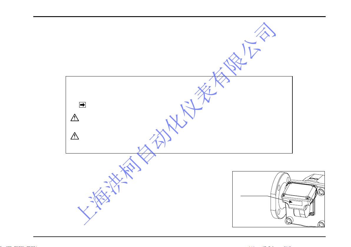
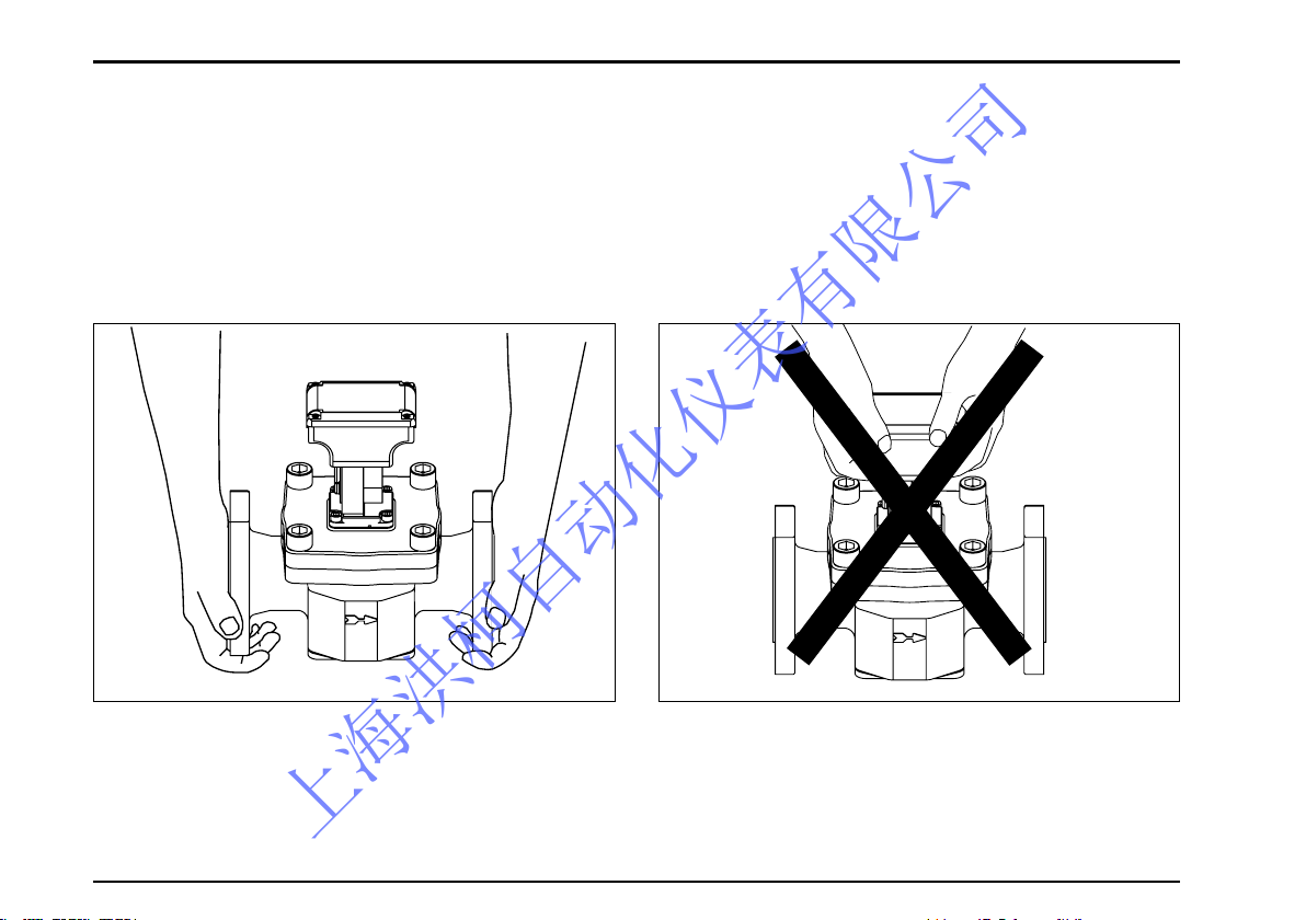
1.2 Transportation Precautions
(1) In order to safeguard against damage during transportation, transport the instrument to the installation
location in the style packaged from our factory if possible.
(2) This instrument is adjusted and inspected as an assembly consisting of the flowmeter, pulse generator
(sensor) and register. It should therefore be handled as an assembly at all times; you should not attempt to
separate the register.
(3) During transit, exercise care not to give impact shocks to the register.
〈Hold like this.〉 〈Don,t hold like this.〉
上海洪柯自动化仪表有限公司
S-179-1-E
1.3 Storage Precautions
If the instrument is to be stored over an extended period of time before installation, it could be involved in unexpected happenings. So if an extended period of storage is anticipated, the following precautions should be taken:
(1) The instrument should be stored in the style packaged in our factory if circumstances permit.
(2) Select a storage location that meets the following reguirements:
* where it is free from rain and water.
* where vibration and impact shocks are least encountered.
* where temperature and humidity in the storage location are as near to the room temperature and humidity
(25℃ and 65% or so).
(3) If you store the instrument which has been placed in service for any length of time, it should be purged with
clean air or N2 gas, etc. to keep the metered material from adhering to the flowmeter couplings, pipeline,
housing, etc.
(4) Use caution to keep the register away from thinner, alcohol or other organic solvents.
Do not attempt to disassemble the register and modify in any way.
(We cannot guarantee performance of modified Flowpet. )
CAUTION
上海洪柯自动化仪表有限公司
S-179-1-E
1.4Installation Location Precautions
(1) In this register, a magnetic sensor is used to pick up magnetic fields of signaling magnets embedded in the
rotor. For this reason, the instrument should be installed sufficiently away from sources generating magnetic
field. If a magnetic valve 10 watts or so is used, separate it at least 10 centimeters from the flowmeter
(depending on operating conditions).
(2) Application in cold regions
To prevent the meter from freezing, install it indoors (in the boiler room, for example).
① A vertical run is recommended for ease of pipeline drainage. Provide a drain plug. (See pipeline drawing
on pages 18 and 19.)
② Lagging is necessary. The register, strainer cover and drain plug should not be lagged, however. Take into
consideration simple and ready separation of the meter from the piping assembly.
(3) This register operates at temperatures between
− 10 to + 60゜C. If exposure to elevated tempera-tures is expected by the direct rays of the sun, reflected
heat, etc., protect the register against heat with a sunshade or heat shield to ensure its operation within the
specified temperature range.
(4) This register is designed for indoor use: install in a location free form rainwater, oil, sunlight.
If exposure to rainwater is unavoidable, provide an appropriate rain guard or sunshade.
2. OPERATING CONDITIONS
To derive the high accuracy and long life from this meter, it is necessary that the meter be used within the
specified conditions in flowrate, pressure, temperature and viscosity. These operating conditions are stated on
the nameplate of flowmeter,s register and in the general specifications in Section 12 of this instruction manual.
Familiarize yourself thoroughly with these instructions before installation and operation.
CAUTION
Under the Measurement Law, this instrument is not serviceable for cer tifying and
authenticating legal transactions.
上海洪柯自动化仪表有限公司
S-179-1-E
7
Nameplate
3. GENERAL DESCRIPTION
The FLOWPET-5G is an OVAL flowmeter primarily intended for use in boiler feed water and fuel oil metering
applications. Field proven accuracy and long life along with the best price/performance and ease of use make
this industrial meter ideal as a dedicated tool for heat control.
3.1 Features
1. Available in two product families - for water service and fuel oil service.
2. Newly designed electronic register shows total flow and instantaneous flow on a digital LCD at the touch of
ode select button. The display angle can be adjusted for better visibility (Adjustable range: 75 degrees upward,
75 degrees downward).
3. The electronic register equipped models have an internal battery (good for 8 years); eliminates the need for an
external power source. (Operation on external power source is recommended for external output equipped
models.)
4. Improved display capabilities compared to the previous EG register.
・LCD character height increased to 14mm from 10mm
・Flow indicator allows user to intuitively check instantaneous flow rate
5. Factored pulse width is variable in 1ms steps with the back side buttons (adjustable 1 to 999ms).
6. Simulated outputs available. (external output equipped meter only) Pulse and analog output can be simulated
at any flow rate for loop tests.
7. Reliable engineering unit pulses for total flow and fast pulse output are available.
8. Analog output available (2-wire, 4 to 20mA)
IMPORTANT: Read this instruction manual thoroughly before you start working on piping and
initiate operation. See Section 4 for piping instructions and Section 7 for operating instructions.
CAUTION
上海洪柯自动化仪表有限公司
S-179-1-E
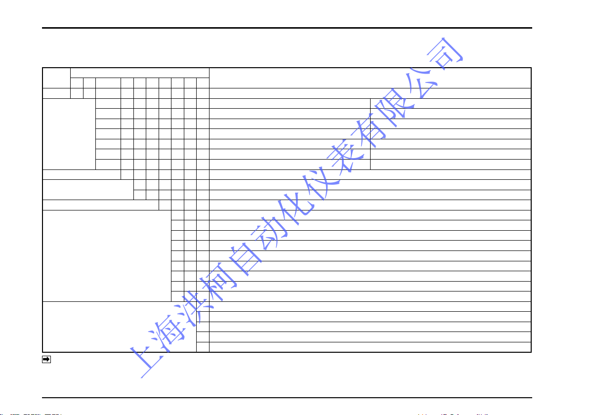
3.2 Product Code Explanation
In this instruction manual, the following combinations of products are described:
Item
Code (Digits)
Description
① ② ③ ④ ⑤ ⑥ − ⑦ ⑧ ⑨ ⑩
Model L S Dedicated Oval flowmeter (Standard model)
Meter Size
(Nominal dia.)
Water service Oil service
4 9 — 20mm (3/4")
5 0 — 20mm (3/4")
5 2 20mm (3/4") 25mm (1")
5 3 25mm (1") 40mm (1•1/2")
5 5 40mm (1•1/2") 40mm (1•1/2") Standard model only
5 6 50mm (2") 50mm (2") Standard model only
Model Name 7 Flowpet
Application
6 − Oil service
7 − Water service
Register 5 Register(5G)
Pulse Generator (※3)
0 0 No output capability (Local display only)
3 0 Factored pulse (pulse width 1ms), +Unfactored pulse (※1)
5 0 Factored pulse (pulse width 50ms), +Unfactored pulse (※1)
6 0 Factored pulse (pulse width 100ms), +Unfactored pulse (※1)
7 0 Factored pulse (pulse width 250ms), +Unfactored pulse (※1)
3 1 Factored pulse (pulse width 1ms), +Unfactored pulse (※1) +Analog output or Analog output only (※2)
5 1 Factored pulse (pulse width 50ms), +Unfactored pulse (※1) +Analog output
6 1 Factored pulse (pulse width 100ms), +Unfactored pulse (※1) +Analog output
7 1 Factored pulse (pulse width 250ms), +Unfactored pulse (※1) +Analog output
Temperature Range
A Oil service: Stndard (0 to 120℃), JIS 10K RF
B Oil service: Stndard (0 to 120℃), ASEM 150 RF
B Water service: Stndard (0 to 120℃), JIS 10K RF
C Oil service: Stndard (0 to 150℃), JIS 10K RF
D Oil service: Stndard (0 to 150℃), ASEM 150 RF
Note: ※1 Unfactored pulse width is xed at 2ms.
※2 If using analog output only, "Factored pulse (1ms) + Unfactored pulse (2ms) + Analog output" will be the specication.
Wire analog output lines (2 lines of the power wire) and leave the ends of pulse output (SIG.1 and SIG.2) cables open (not connected).
※3 Alarm output specication is available as an option.
上海洪柯自动化仪表有限公司
S-179-1-E
9
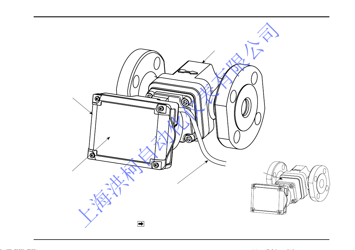
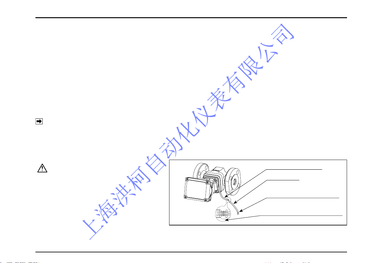
3.3 Part Names
METER BODY
REGISTER
LCD DISPLAY
※ CABLE (1m LONG)
COOLING
BLOCK
HIGH TEMP. MODEL
(NOTE) Only external output equipped meters are furnished with the
cable shown here with an asterisk
※ .
上海洪柯自动化仪表有限公司
S-179-1-E
10
4. PIPING
4.1 Piping Precautions
(1)Install the meter, exercising care to avoid pipe strains.
(2)The meter should be installed downstream of the pump.
(3)Provide a strainer upstream of the meter.
(NOTE)The strainer net used is 80 mesh for nominal size 20mm and 60 mesh for sizes 25 through 50mm.
(4)Install the pump taking into consideration the pressure loss of the entirre piping system. In case where the
material is allowed to flow by means of a head instead of using a pump, a pressure (head) greater than the
pressure loss of the piping system, flowmeter, strainer, etc. should be given.
(5)To prevent inductive interferences, please be sure to connect to the earth ground for instrumentation one of
the four mounting bolts securing the register with the flowmeter body, instead of the ground terminal.
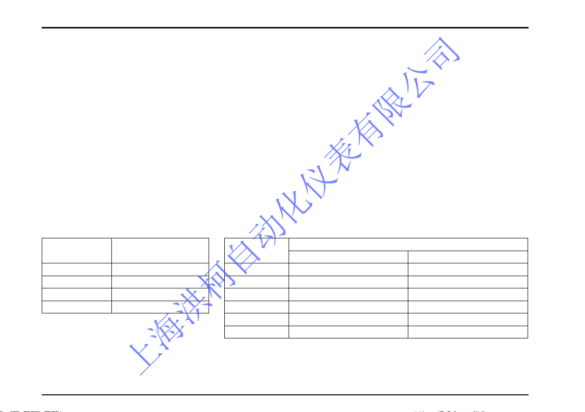
● Pressure Losses of Flowpet
〈Water
Service
〉
Model
Pressure Loss
kPa
LS5277 5 ( 1200 L/h)
LS5377 12 ( 3600 L/h)
LS5577 10 ( 7200 L/h)
LS5677 7 (12000 L/h)
〈Oil
Service
〉
Model
Pressure Loss kPa
Kerosene 1.2mPa•s Heavy oil 19mPa•s
LS4976 32 ( 800 L/h) 47 ( 800 L/h)
LS5076 14 (1600 L/h) 40 (2000 L/h)
LS5276 13 (3000 L/h) 56 (3800 L/h)
LS5376 13 ( 5 m3/h) 30 (6.4 m3/h)
LS5576 25 (11 m3/h) 54 ( 14 m3/h)
LS5676 27 (20 m3/h) 55 ( 24 m3/h)
上海洪柯自动化仪表有限公司
S-179-1-E
11
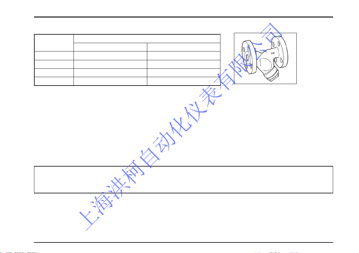
Strainer
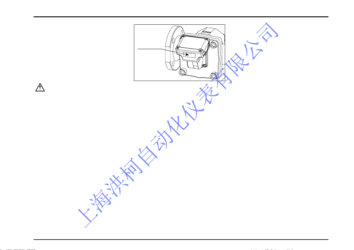
(6) Align the flow direction with the arrow mark on the meter body.
(7) The pulse generator of this meter makes use of the changes in magnetic flux. To minimize influence of exter nal magnetic fields, select an installation location sufficiently away from powerful magnets and conductors
creating strong magnetic fields.
(8) If electric heating is desired, consult factory.
(9) When you conduct a gastight test on the existing piping assembly, careful valve operations sequence is
required to safeguard the rotors against damage due to violent rotor spinning by rushing air currents. Adhere
to the instructions on operation sequence described on page 32.
● Strainer Pressure Losses
Model
Pressure Loss kPa
Kerosene 1.2mPa•s Heavy oil 19mPa•s
LS5278A 6 ( 300 L/h) 50 (3800 L/h)
LS5378A 7 ( 5 m3/h) 28 (6.4 m3/h)
LS5578A 23 (11 m3/h) 26 ( 14 m3/h)
LS5678A 25 (20 m3/h) 40 ( 24 m3/h)
CAUTION: This model is not provided with subtract counter function. In applications where ripples
(to-and-fro motion of the fluid under ripple pressure) or reverse flows exist in the pipeline, the total
counter reading may not be consistent because it adds up flows irrespective of the flow direction.
上海洪柯自动化仪表有限公司
S-179-1-E
1
4.2 Flushing the Piping Assembly
Be sure to remove the meter from the piping assembly and intall a short pipe section in place of the meter.
Flushing the piping assembly with the meter in place will result in serious, costly damage to the meter’s
measuring chamber.
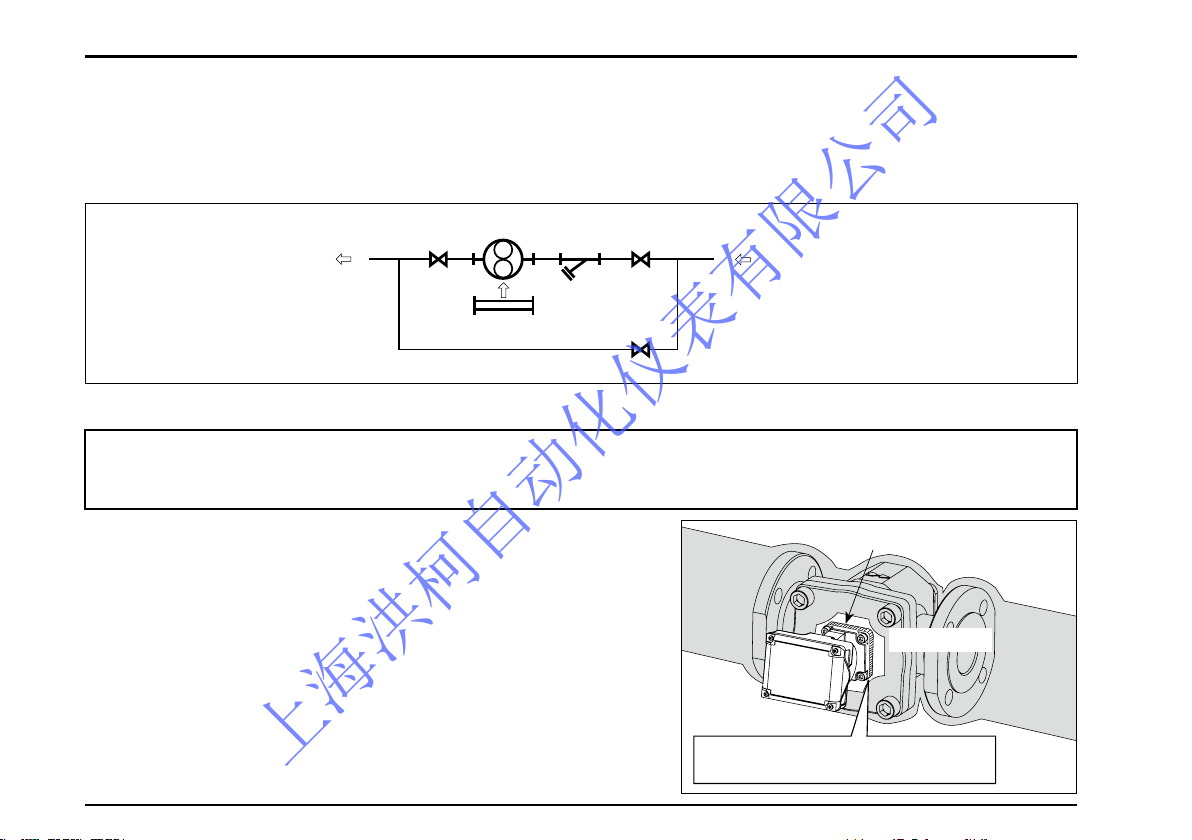
4.3 Lagging Work Precautions
(1) Be sure to inspect for liquid leaks before covering with lagging.
(2) Take into consideration simple and readily disassembly and
inspection for the lagging of the meter.
(3) Strainer should be lagged for quick top cover removal.
Strainer net should be cleaned on a regular basis.
(4) Register and pulse generator must not be lagged. If they
are lagged, temperature will rise to an excessive level and
result in costly damage (see figure on the right).
(5) Heat insulation should not cover up the front cover register
seat.
(6) In applying heat insulation, take into account the ease of
removal and disassembly.
Register Fitting Seat
Allow a clearance around the register
fitting seat for heat retention.
Lagging Seat
FLOW DIRECTION
STRAINER
SHORT PIPE
BYPASS LINE
VALVE
METER
For applications where the meter is to be placed in service in cold regions or where
solidifying materials (e.g. Heavy oil) are to be metered, lagging work for the flowmeter and
strainer is required.
上海洪柯自动化仪表有限公司
S-179-1-E
1
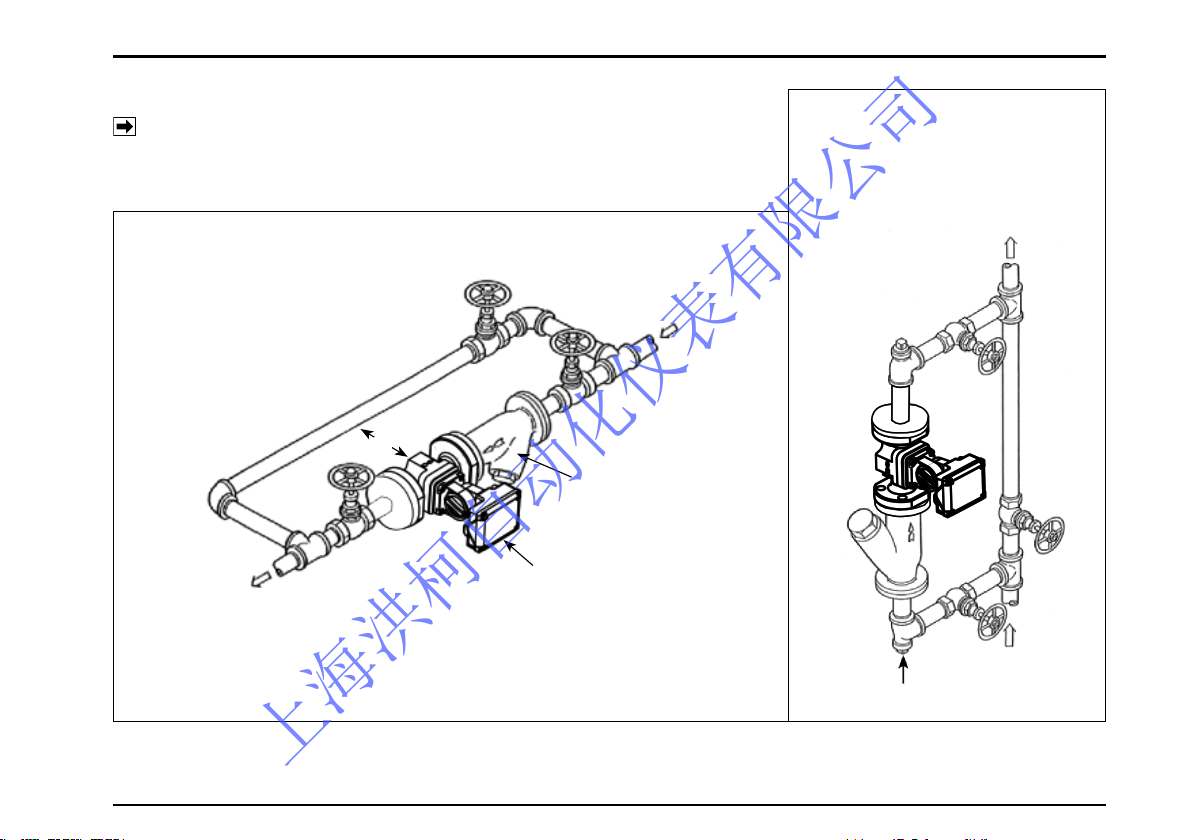
4.4 Examples of Installation
NOTE: Make pipe connections observing the instructions under the
topic“Piping Precautions”on Section 4.1.
●
Vertical Line
Install in the bypass side to prevent scales falling from top of the
piping assembly.
Marked ※ is the space required for disassembly and inspection.
Secure at least 600mm.
● Horizontal Line...........standard piping
BYPASS
IN
STRAINER
FLOWPET-5G
IN
OUT
DRAIN VALVE
OUT
※
上海洪柯自动化仪表有限公司
S-179-1-E
1
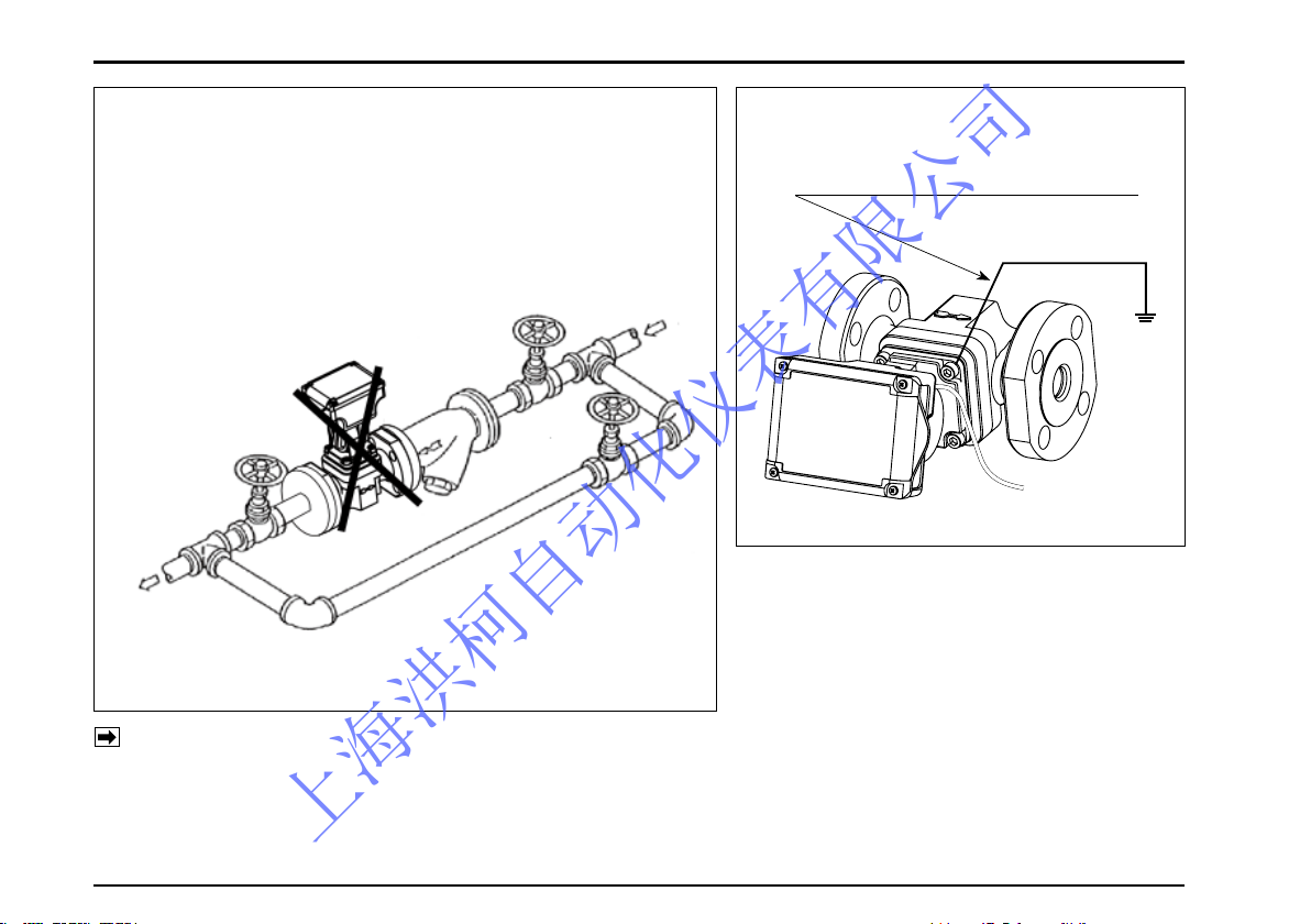
●
Example of Incorrect Piping
◎
Do not install the meter in a position like this.
(Installation is correct if the measuring chamber is on a level
plane.)
To change flow directions, register face directions, see Section 4.5 (2).
If the flowmeter is equipped with external output capability, make electrical connections according
to the wiring instructions in Section 5.
WRONG
●
How to prevent inductive interferences
Connect to the earth ground by using
one of the mounting bolts
BYPASS
STRAINER
FLOWPET-5G
IN
OUT
(Note)
上海洪柯自动化仪表有限公司
S-179-1-E
1
ARROW MARK
( )
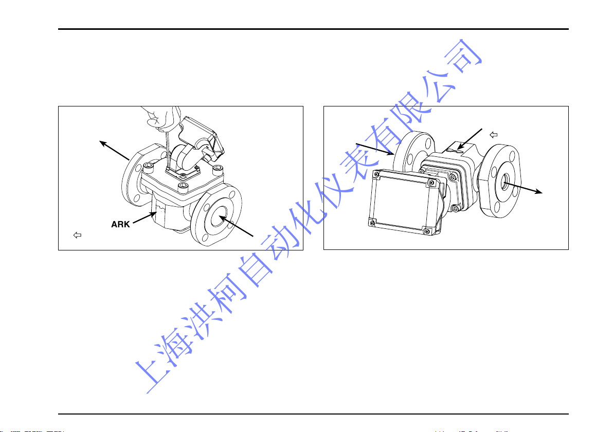
4.5 How to Change the Flow Directions and Display Orientations
(1) How to change the flow directions
The Flowpet is assembled to accept the flow from right to left. Flow directions can simply and readily be
changed in the following manner:
①Remove the meter from the pipeline and separate
the register from the meter body. Aligin the arrow
mark indicating the flow direction with the flow
direction. In case of changing the flow direction
from R-to-L to L-to-R, turn the meter body as shown
in the sketch and reinstall in the pipeline.
OUT
IN
IN
OU
T
ARROW MARK
( )
②Align the physical orientation of the register correct-
ly as shown and retighten the bolts. The same
applies to changing the directions from L-to-R to
top-to-bottom or bottom-to-top.
上海洪柯自动化仪表有限公司
S-179-1-E
1
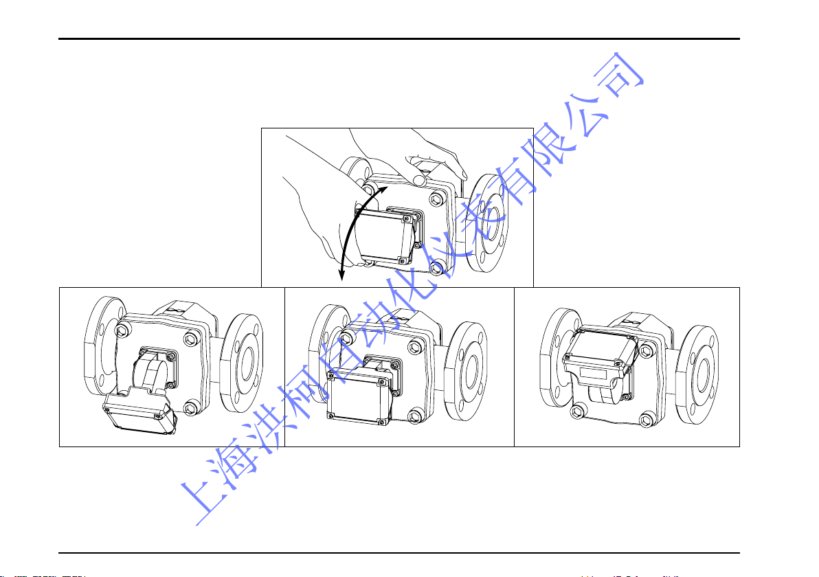
(2) How to change the register orientation
The register display can be easily adjusted by click stop in 15 deg. increment to a desired direction for
maximum viewability. The adjustable range is 150 deg. upward or downward. See the sketches below.
〈Tilted Downward (or Upward)〉 〈Facing Forward (Horizontal)〉 〈Facing Upward (or Downward)〉
上海洪柯自动化仪表有限公司
S-179-1-E
17
Attached cable 1 meter long
5. WIRING
In case of external output capability equipped models LS□□7 -5 , make electrical connections as follows.
Also refer to the instruction manual for the receiving instrument (topic under“Wiring Instructions”) to be used.
5.1 Field wiring
(1) This flowmeter is furnished with 1 meter long cable (vinyl-sheathed, 4-conductor, individual elements
AWG24). To extend the cable, make sure to use shielded cable (CVVS: 1.25 to 2.0mm2) and extend the
shield as well. Leave the extended cable open at its end (no contact).
(2) Transmission length
With transmission cables (CVVS: 1.25 to 2.0mm2), the maximum transmission length is one kilometer. If
using both analog output and pulse output, the transmission distance is 100m max.
NOTE: If transmission length exceeds one kilometer, consult factory.
(3) Prevention of inductive interference
Route the field wiring sufficiently away from existing power cables or power circuits, if any, to minimize
possible stray current pickup.
6
7
3
5
6
7
Make sure of the validity of flowmeter
(p u l s e g e n e r a t o r ) a n d r e c e i v i n g
instrument combination by referring to
their model number, serial number, etc.
before you make electrical connections.
A
B
C
D
The shields of both cables are connected
Extension cable
Leave the end of shield open.
(Do not connect to the earth ground)
CAUTION
0
1
上海洪柯自动化仪表有限公司
 Loading...