

Page 1
Ins. No. E-886-2-E
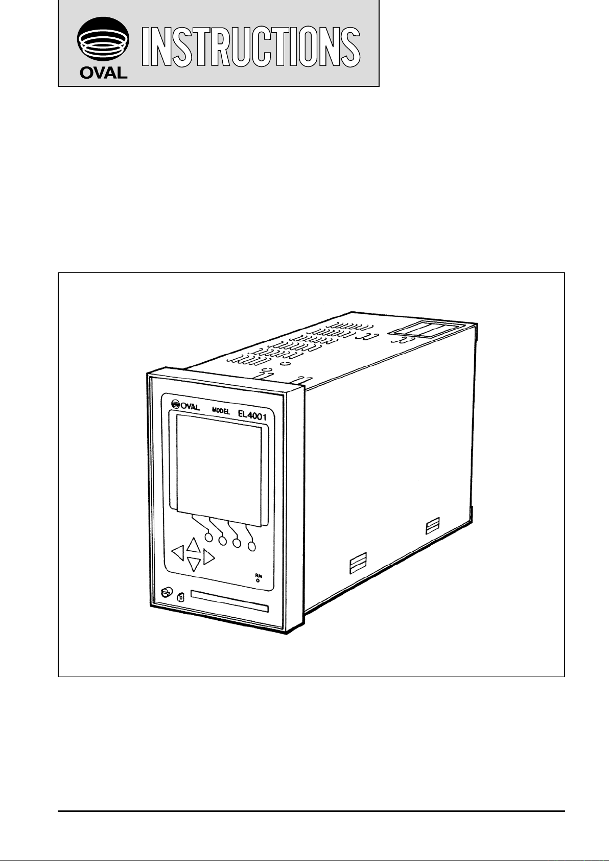
DENSITY COMPUTER
Model EL4301: Density Computer for Mass Flowmeter
Model EL4311: Density Computer for Mass Flowmeter
(with solids proportion calculation feature)
Model EL4321: Density Computer for Spool Densitometer
(gas service)
Model EL4331: Density Computer for Spool Densitometer
(liquid service)
This manual has been prepared to provide you with the information pertinent to the DENSITY
COMPUTERS. These models have the description in common except where noted.
With the proper application of the information and knowledge contained in this manual, you can
expect the best possible results over a long service life of these instruments. Keep this manual for
ready reference.
It is suggested that the instruction manuals for the companion pulse generator (flowmeter) and
receiving instrument be referred to at the same time.
1
Page 2

E-886-2-E
TABLE OF CONTENTS
Page
1. BEFORE YOU BEGIN ............................................................................................................ 4
1.1 Confirming the Nameplate .................................................................................................... 4
1.2 Transportation Precautions ...................................................................................................4
1.3 Storage Precautions ............................................................................................................. 4
2. GENERAL ................................................................................................................................ 5
2.1 Features ................................................................................................................................5
2.2 Part Names ........................................................................................................................... 5
3. INSTALLATION ....................................................................................................................... 6
3.1 Outline Dimensions ...............................................................................................................6
3.2 Installation .............................................................................................................................6
3.2.1 Installation Location ........................................................................................................6
3.2.2 Panel ..............................................................................................................................6
3.2.3 Installation ......................................................................................................................6
4. WIRING .....................................................................................................................................7
4.1 Field Wiring Cables ...............................................................................................................7
4.2 Wiring Connections ...............................................................................................................7
4.3 Description of Terminal Blocks for External Connections .....................................................7
4.3.1 Terminal Identification ..................................................................................................... 8
5. PRODUCT CODE EXPLANATION ................................................................................... 10
6. INTERNAL COMPONENTS AND FUNCTIONS .............................................................12
6.1 Front Panel ......................................................................................................................... 12
6.1.1 Display ..........................................................................................................................12
6.1.2 Front Panel Keypad ......................................................................................................12
6.1.3 Error Messages ............................................................................................................ 12
6.1.4 Display Items ................................................................................................................ 13
7. CALCULATION FORMULAS .............................................................................................15
8. PREPARATIONAL CHECKS AND OPERATION ........................................................... 17
8.1 Preparation Before Operation ............................................................................................. 17
8.2 Preparational Checks ......................................................................................................... 17
8.3 Operation ............................................................................................................................ 17
9. TROUBLESHOOTING ......................................................................................................... 18
10. ERROR MESSAGES............................................................................................................19
11. BEHAVIOR IN ERRATIC CONDITIONS .......................................................................... 19
12. GENERAL SPECIFICATIONS ...........................................................................................20
12.1 EL4301 Density Computer for Mass Flowmeter ............................................................... 20
12.2 EL4311 Density Computer for Mass Flowmeter
(with solids proportion flowrate calculation feature) .......................................................... 21
12.3 EL4321 Density Computer for Spool Densitometer (gas service) .................................... 22
12.4 EL4331 Density Computer for Spool Densitometer (liquid service) .................................. 23
13. OVERALL BLOCK DIAGRAM ...........................................................................................24
Page 3

E-886-2-E
COMPANION VOLUME
KEY OPERATION MANUAL Ins. No. E-880TM-E
CONTENTS
1. KEY ARRANGEMENT .........................................................................................................10
2. DISPLAY SCREEN ............................................................................................................... 11
3. INITIAL CHECK ..................................................................................................................... 14
4. MODE SELECTION ..............................................................................................................18
5. RUN MODE SCREEN .......................................................................................................... 23
6. SET MODE ............................................................................................................................. 36
7. SYS MODE ..........................................................................................................................142
8. ABOUT EL4401 ................................................................................................................... 170
9. ABOUT EL4501 ................................................................................................................... 175
10. DIP SWITCH CONFIGURATION ..................................................................................... 182
(※: Model with communication capabilities)
COMMUNICATION MANUAL (※) Ins. No. E-880CM-E
CONTENTS
1. COMMUNICATION CAPABILITY OVERVIEW .................................................................. 5
2. NETWORK CONFIGURATION ............................................................................................5
3. MODE SELECTION ................................................................................................................6
4. LOCAL / REMOTE SELECTION .......................................................................................... 8
5. SETUP ITEMS FOR COMMUNICATION ......................................................................... 10
6. COMMUNICATION PROCEDURE .................................................................................... 11
7. COMMUNICATION FORMAT .............................................................................................12
8. BCC / SUM CHECK ..............................................................................................................45
9. CR / LF ....................................................................................................................................46
10. CODES ASSIGNED TO UNITS ..........................................................................................48
11. ASCII CODE ...........................................................................................................................49
Page 4

E-886-2-E
1. BEFORE YOU BEGIN
Every OVAL product is thoroughly tested and inspected before shipment from our factory.
When received, its appearance should be inspected for possible damage by rough handling during transit. First of all, thoroughly read the handling precautions described in this section. For topics other than
those covered in this section, refer to the respective sections of this manual.
If at any time in the future you seek our assistance, contact the nearest sales office in your area.
1.1 Confirming the Nameplate
The instrument is adjusted to individual specifications before shipment from our factory. Model
number appears on the nameplate attached to the
top of the housing.
Make sure to see that the instrument you received
conforms to the General Specifications (pages 21
through 24) and the Product Code Explanation
(pages 10 and 11).
※
Nameplate
(model number)
※EL4001 is the
generic designation of the
◆ When you inquire, supply complete infor-
EL4001 series
computers.
mation as to the product name, model
number, product number, ratings, and
Fig. 1.1 Nameplate Location
other pertinent information.
1.2 Transportation Precautions
(1) In order to safeguard against damage during transit, transport your instrument to the installation loca-
tion in the original package used for shipment from the factory if possible.
(2) Use care to avoid impact shocks to the instrument during transit.
1.3 Storage Precautions
If the instrument upon receipt is to be stored for extended periods of time before installation, unexpected
problems could arise. If such is the case, the following considerations should be taken:
(1) The instrument can best be stored in the original package used for transit from the factory.
(2) The place of storage should meet the following requirements:
☆ Free from rain and water
☆ Free from vibration and impact shocks
☆ With minimal temperature and humidity variation (around 25°C and 65% R.H.)
Page 5
MODEL
EL4001
TB
1
TB
2
TB
1
TB
2
TB
3
PLS OUT3 TEMP IN TEMP IN FLOW IN
0V
+− B bA+−
+−+− +−
+−
SIG SUP
SUP
ANA OUTGND POWER
N
(
−
)
H
(
+
)
PRESS INPLS OUT1PLS OUT2
1/1
OUT
E-886-2-E
2. GENERAL
In comparison with the previously offered instruments (OVAL EL4080 series), substantial reduction in
physical geometry, improved functions and ease of operation have been achieved. Included among the
improvements in this newly developed instrument are simplified parameter changes and data logging with
IC cards along with a large, easy-to-read LCD display.
Table 2.1
Model Description
This instrument receives tube oscillation signal and temperature signal from the OVAL
EL4301
EL4311
EL4321
EL4331
Coriolis flowmeter and, upon calucation, displays the density of process fluid.
It also can display the density corrected for reference temperature and provide an analog
output.
This instrument receives mass flow signal and temperature/density signals from the OVAL
Coriolis flowmeter and, upon calucation, displays the total flow of solids content of process
fluid that contains solids.
It also can display the density corrected for reference temperature and provide an analog
output.
This instrument receives density frequency signal from the density sensor and provides
an analog output in proportion to the density of metered process fluid. In response to temperature and pressure signals (EL4321 only), it also can provide an output corrected for
reference conditions.
2.1 Features
(1) Performs calculation of density corrected for temperature.
(2) Changing the ranges of density, temperature, pressure, or other parameters, of the companion densi-
tometer is simple by keystrokes on the front-panel keypad or by inserting an IC card into the slot.
(3) A built-in CPU offers a high degree of performance and accuracy.
(4) Variables such as temperature, pressure, and density can be reviewed on command with the front
panel keypad, whether or not computation is in progress.
(5) A nonvolatile memory (E2PROM) retains all parameters in the event of an AC power failure.
(6) Displays the percent concentration of solids content in the slurries and provides its analog output
(EL4301 only).
(7) Produces high and low density alarm outputs (set to desired limits) (EL4301 only).
(8) If an error occurs, its nature is identified as an error message on the display.
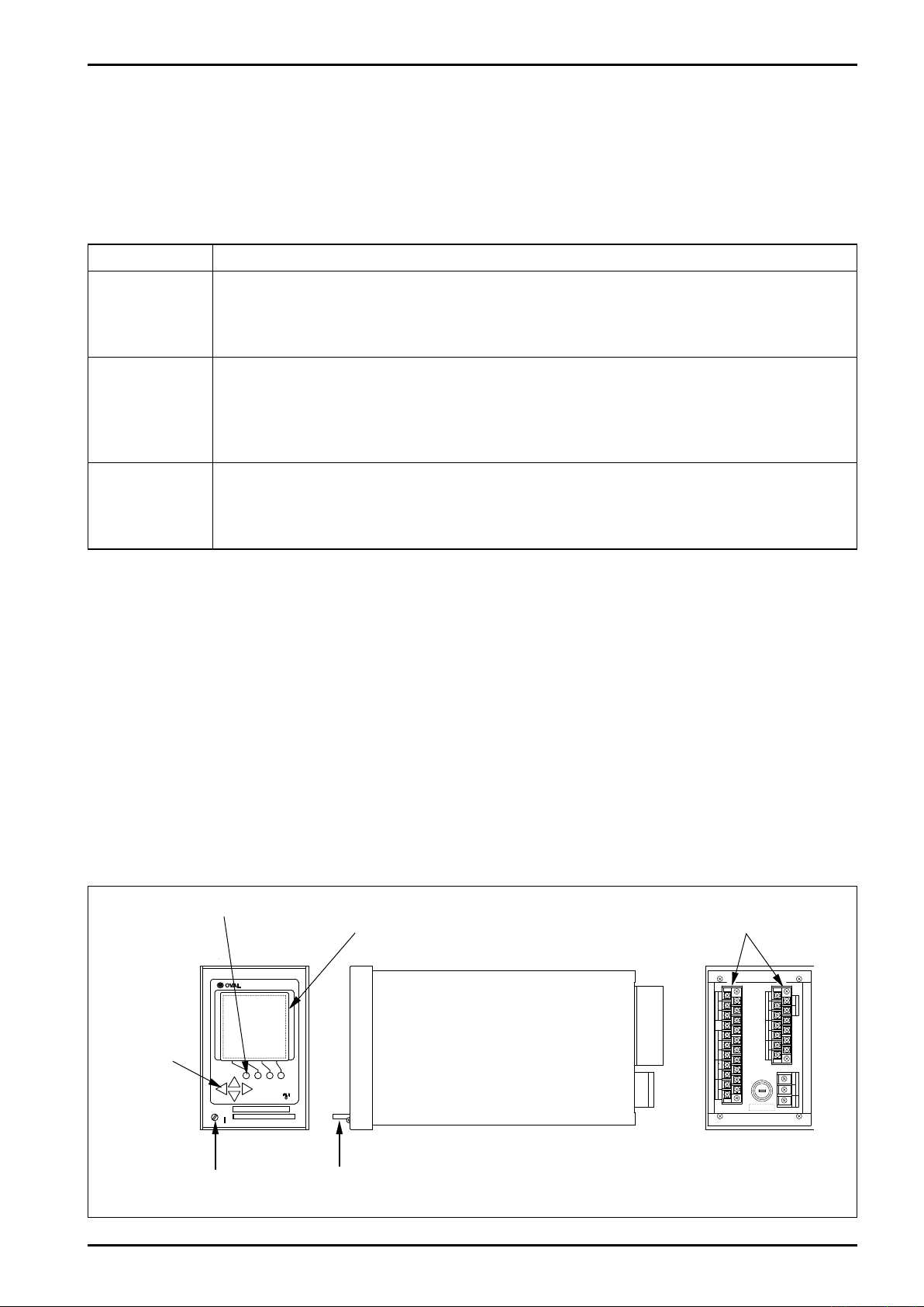
2.2 Part Names and Functions
Function Keys
Display
Terminal Blocks
Shift Keys
Seal Screw
IC Card (option)
Fig. 2.1 Part Names
Page 6
TB
1
TB
2
TB
1
TB
2
TB
3
PLS OUT3 TEMP IN TEMP IN FLOW IN
0V
+− B bA+−
+−+− +−
+−
SIG SUP
SUP
PLS OUT2GND POWER
N
(
−
)
H
(
+
)
PRESS INANA
PLS OUT1
1/1
OUT
MODEL
EL4001
912596
20 232.4
144
136
E-886-2-E
Optimum
Range
600
1800
450 Acceptable Range
2200
Computer
Min.120
Min.220
92
±0.8
0
+1
138 0
3. INSTALLATION
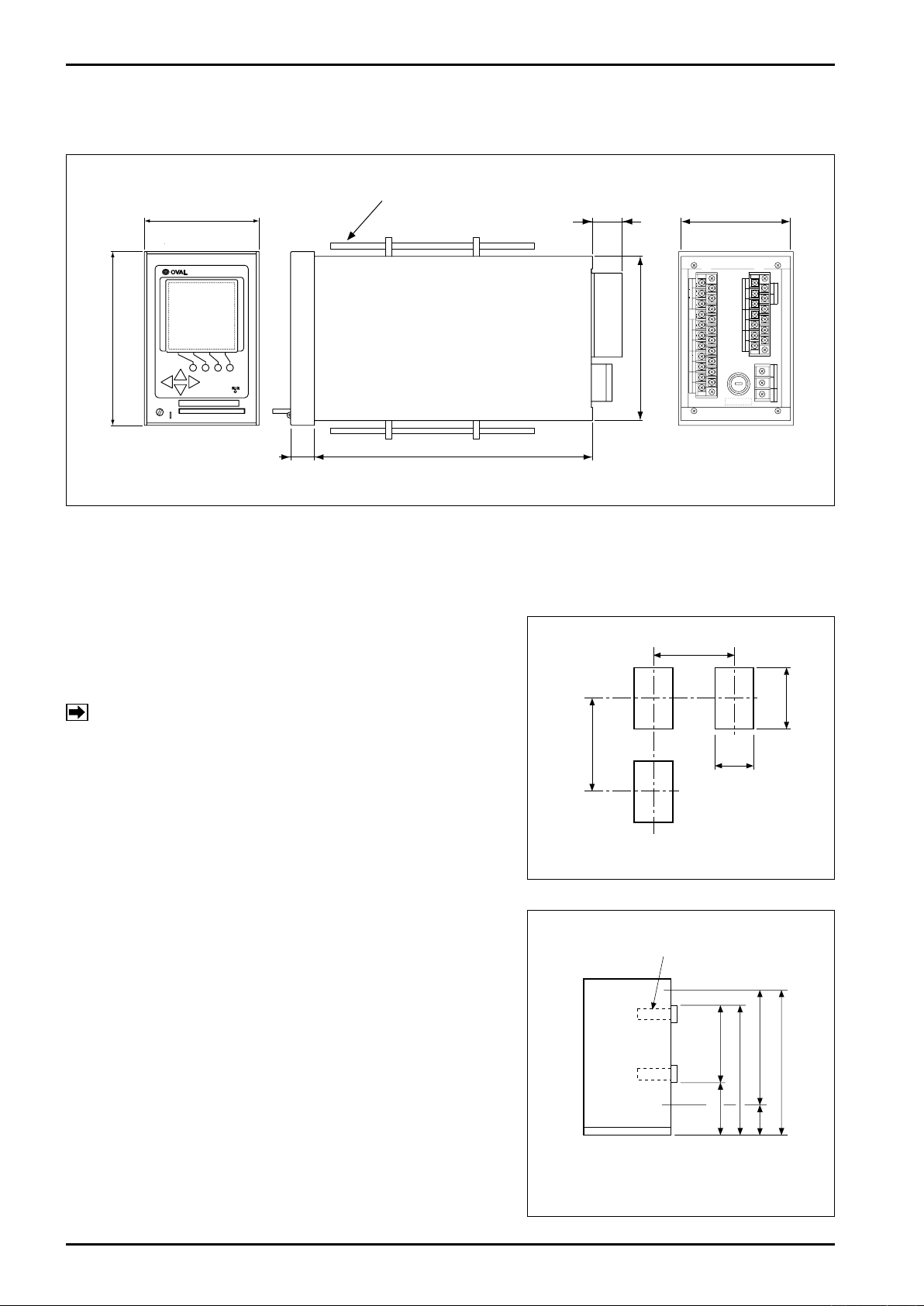
3.1 Outline Dimensions
All dimensions in millimeters
Hold-down Fitting
Fig. 3.1 Outline Dimensions
3.2 Installation
3.2.1 Installation Location
Select an installation site where:
(1) Mechanical vibration, shock and corrosive gases are
negligible.
(2) Air is dry and temperature at room temperature and
stable.
NOTE: Although the manufacturer guarantees stated
performance at ambient temperatures up to
+50°C, it is recommended that the instrument
be placed in service at room temperature.
(3) Provide a sufficient working space behind the instru-
ment - at least 50 centimeters from the back panel of
the instrument to facilitate wiring and servicing.
3.2.2 Panel
(1) Use a rigid steel sheet with a minimum thickness of 1.6
millimeters. 3.2mm thick is recommended.
(2) If it is required to install instruments alongside each
other, dimensions in Fig.3.2 are suggested.
(3) Recommended mounting height is given in Fig. 3.3.
Fig. 3.2 Panel Cut
3.2.3 Installation
(1) Front mount the instrument through the cutout in the
panel.
(2) Fit the furnished enclosure hold-down fittings into the
top and bottom slots in the enclosure and, confirming
that the instrument is positioned horizontal, secure the
instrument to the panel with hold-down fittings (Fig. 3.1).
Fig. 3.3 Instrument Mounting Height
Page 7
E-886-2-E
TB
1
TB
2
1
2
3
TB
3
PLS OUT3 TEMP IN TEMP IN FLOW IN
0V
+− B bA+−
+− −+−
+−+− +−
+−
SIG SUP
0V SIG SUP
SUP
ANA OUT
GND POWER
N
(
−
)
H
(
+
)
PRESS INPLS OUT1
COMM1
COMM2
TEMP
PLS OUT2
1/1
OUT
DENSITY IN
4. WIRING
(See the Wiring "Guidelines" in the instruction manual of the companion pulse generator.)
4.1 Field Wiring Cables
(1) Use electrostatically shielded, polyethylene insulated, vinyl sheathed control cables (CEVS, 1.25-2
mm, 2-conductor or 3-conductor), or equivalent, for input signal cables from the flowmeter.
For output signal cables, use insulated vinyl sheathed cables (CVV, CVS ... JIS C 3401).
(2) Ground the end of shield wire to "G" terminal of the instrument. At the sensor end, leave the end of
shield wire unconnected.
4.2 Wiring Connections
(1) Field wiring through a conduit is recommended.
NOTE: In routing field wiring, use a separate conduit for power cable from other signal cables to
eliminate the possibility of stray current pickup.
(2) Separate field wiring from other power lines and power circuits to minimize the possibility of inductive
interference.
(3) Using crimp-type lugs for wiring, ensure good electrical coannections.
Terminals are found on the back of the instrument (Fig. 4.1).
4.3 Description of Terminal Blocks for External Connections
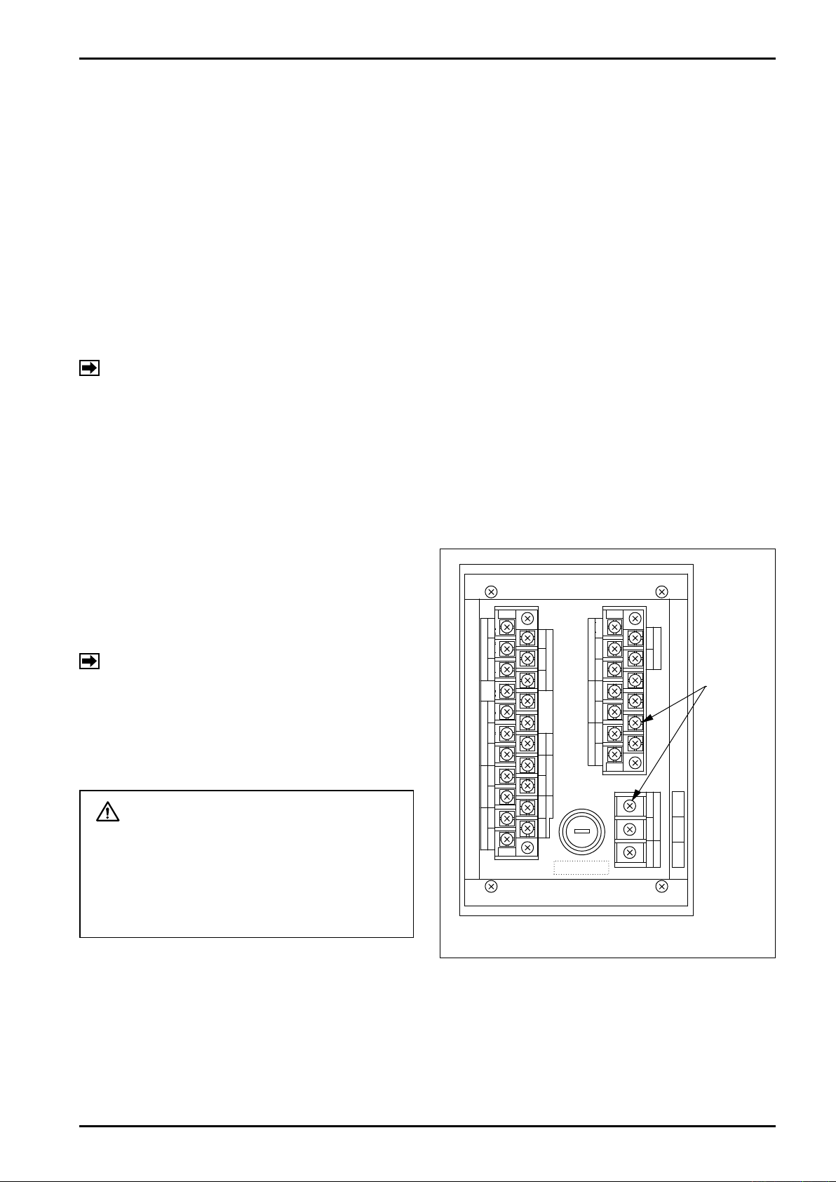
Terminal blocks for external connections (TB1, TB2,
and TB3) are found on the back of the instrument
as shown in Fig. 4.1. Identification of terminals
and connection method appear in Section 4.3.1
"Terminal Identifications (1) and (2)" that follow.
NOTE: TB1 and TB2 terminal numbers are
indicated on the side of terminal blocks.
CAUTION
Make wiring connections upon confirmation of the validity of flowmeter (pulse
generator) to receiving instrument combination by their product code number,
instrument number, etc.
Fig. 4.1 Terminal Blocks for Ext. Connections
Terminal
Screws
(M3.5)
Page 8

E-886-2-E
4.3.1 Description of Terminals
(1) Terminal Identification
Table 4.1 EL4301 Terminal Identification
TB1
No. Label No. Label
1 12 SUP.
2 13 SIG.
3 14 0V
4 15
5 b
6 B 17 - Temp. in
7 A 18 +
8 + 19 -
9 - 20 +
10 +
11 -
Temp. in
Alarm out 3
16
21 -
Density in
Comm 1
※
Comm 2
※
No. Label No. Label
1 8 +
2 9 -
3 10
4 +
5 - 12
6 +
7 -
Analog out
Alarm out 1
TB2
11
13
1 H (+)
2 N (-)
3 GND
Alarm out 2
TB3
Power
NOTE ※: Model provided with communication interface.
NOTE: If transmitter (MT9411) temperature terminals (TEMP. ②) are used, shortcircuit TB1-14 and TB1-17.
Table 4.2 EL4311 Terminal Identification
TB1
No. Label No. Label
1 SUP.
2 SIG. 13 SIG.
3 0V 14 0V
4 OUT 1/1 15
5 b
6 B 17 - Temp. in
7 A 18 +
8 + 19 -
9 - 20 +
10 +
11 -
Flow in
Temp. in
Alarm out
12 SUP.
16
21 -
Density in
Comm 1
※
Comm 2
※
NOTE ※: Model provided with communication interface.
No. Label No. Label
1 8 +
2 9 -
3 10
4 +
5 - 12
6 +
7 -
Analog out
Pulse out 1
TB2
11
13
1 H (+)
2 N (-)
3 GND
Pulse out 1
TB3
Power
NOTE: If transmitter (MT9411) temperature terminals (TEMP. ②) are used, shortcircuit TB1-14 and TB1-17.
Table 4.3 EL4321 and EL4331 Terminal Identification
TB1
No. Label No. Label
1 12 SUP.
2 13 SIG.
3 14 0V
4 15
5 b
6 B 17 - Temp. in
7 A 18 +
8 + 19 -
9 - 20 +
10 +
11 -
Temp. in
Alarm out
16
21 -
Density in
Comm 1
※
Comm 2
※
No. Label No. Label
1 SUP.
2 + 9 -
3 - 10
4 +
5 - 12
6 +
7 -
Press. in
(EL4321 only)
Analog out
Pulse out 1
NOTE ※: Model provided with communication interface.
NOTE ※1: If 2-wire pressure transmitter is directly coupled, use TB2-1→(+); TB2-2→(-).
(※1)
TB2
8 +
11
13
1 H (+)
2 N (-)
3 GND
Pulse out 2
TB3
Power
Page 9
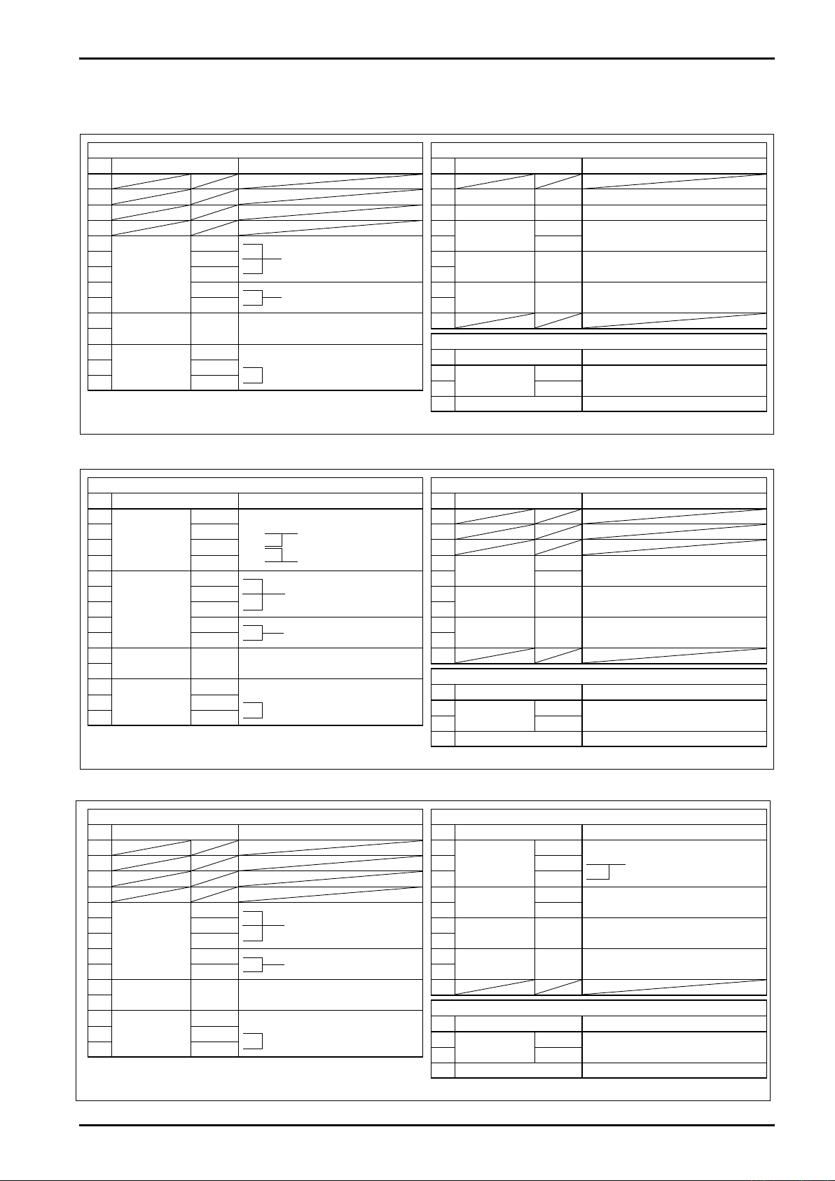
(2) Terminal Connections
E-886-2-E
Table 4.4 EL4301 Terminal Connections
TB1
No. Label Description
1
2
3
4
5
7 A
Temp. in
8 +
9 -
10
Alarm out 3
11
12
Density in
13 SIG.
14 0V
b
No
polarity
SUP.
Pt100Ω 3-wire6 B
4 to 20mADC/1 to 5VDC
or 5mV/°C, 10mV/°C
Alarm out
Static relay
Tube period signal
±5V square wave
Table 4.5 EL4311 Terminal Connections
TB1
No. Label Description
1
2 SIG.
Flow in
3 0V
4 OUT 1/1
5
Temp. in
7 A
8 +
9 -
10
Pulse out 3
11
12
Density in
13 SIG.
14 0V
SUP.
b
No
polarity
SUP.
(+) 2-wire generator
(-)
(+)
Alarm out
Static relay
Output sync with
input signal (O.C.)
Pt100Ω 3-wire6 B
4 to 20mADC/1 to 5VDC
or 5mV/°C, 10mV/°C
Tube period signal
±5V square wave
TB2
No. Label Description
1
2
3
4
Analog out
5 -
6
Alarm out 1
7
8
Alarm out 2
9
10
No. Label Description
1
Power
2 N (-)
3 Ground
Screws on the terminal block: M3.5
No. Label Description
1
2
3
4
Analog out
5 -
6
Pulse out 1
7
8
Pulse out 2
9
10
No. Label Description
1
Power
2 N (-)
3 Ground
Screws on the terminal block: M3.5
+
No
polarity
No
polarity
H (+)
+
No
polarity
No
polarity
H (+)
Corrected density or concentration; 4 to 20mADC/1 to 5VDC
High alarm
Static relay
Low alarm
Static relay
TB3
85 to 264VAC
or 20 to 30VDC
TB2
Instant solids content flow
4 to 20mADC/1 to 5VDC
Total mass flow
Static relay
Total solids content flow
Static relay
TB3
85 to 264VAC
or 20 to 30VDC
Table 4.6 EL4321 and EL4331 Terminal Connections
TB1
No. Label Description
1
2
3
4
5
Temp. in
7 A
8 +
9 -
10
Alarm out
11
12
Density in
13 SIG.
14 0V
b
No
polarity
SUP.
Pt100Ω 3-wire6 B
4 to 20mADC/1 to 5VDC
or 5mV/°C, 10mV/°C
Alarm out
Static relay
Density period signal
162 to 650μs
TB2
No. Label Description
1
2 +
Press. in
3 -
4
Analog out
5 -
6
Pulse out 1
7
8
Pulse out 2
9
10
No. Label Description
1
Power
2 N (-)
3 Ground
Screws on the terminal block: M3.5
SUP. +24VDC
+
Corrected density
4 to 20mA/1 to 5VDC
No
No
Static relay
Static relay
TB3
85 to 264VAC
polarity
polarity
H (+)
4 to 20mADC/1 to 5VDC
or 20 to 30VDC
Page 10
E-886-2-E
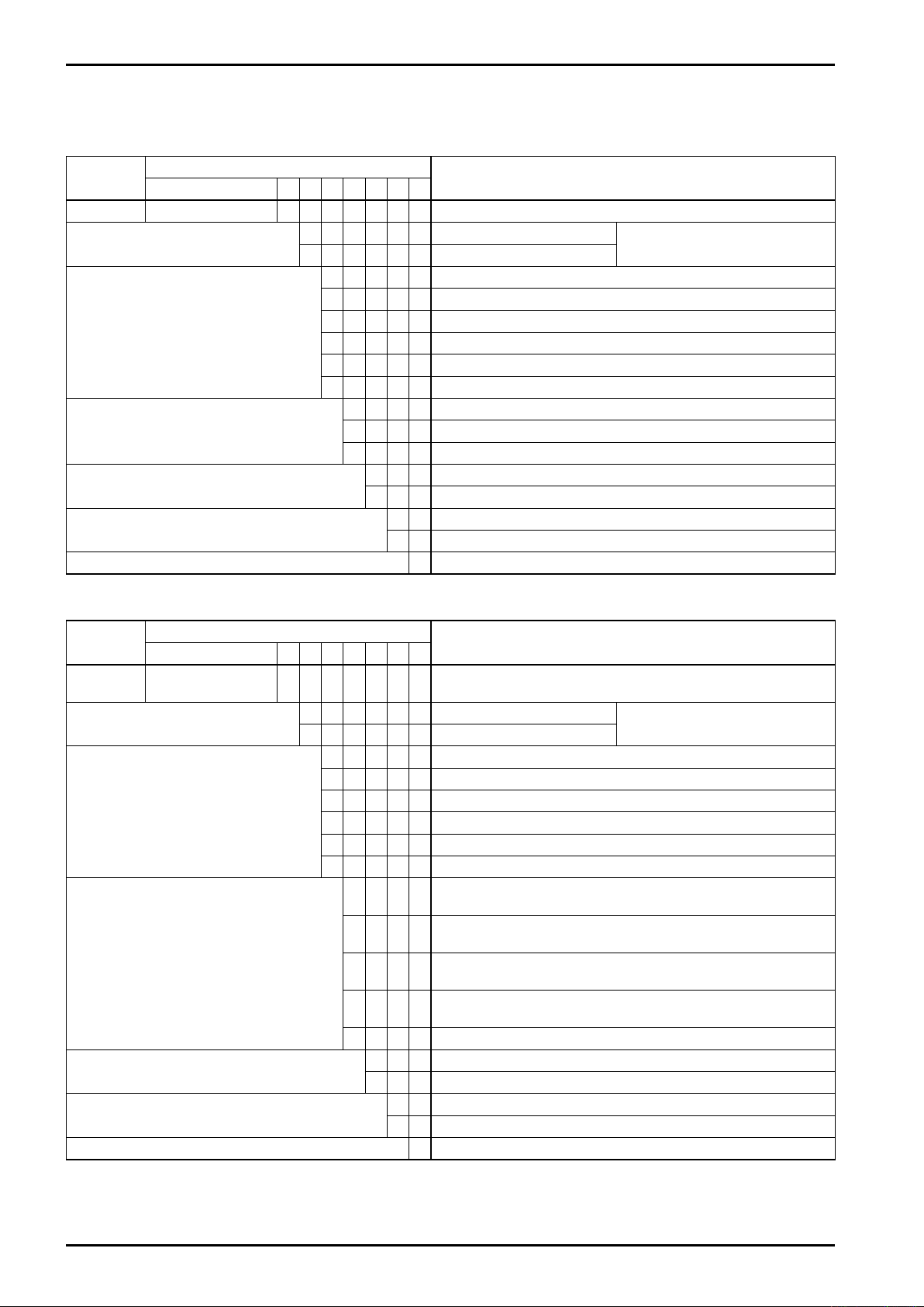
5. PRODUCT CODE EXPLANATION
Table 5.1 EL4301 Product Code Explanation
Item
Model E L 4 3 0 1 Density Computer for Mass Flowmeter
Power
Temperature Input
Analog Output
Sensor Tube Material
Communication Capability
Finish 1 Munsell N1.5
① ② ③ ④ ⑤ ⑥ − ⑦ ⑧ ⑨ ⑩ ⑪ ⑫
Product Code
6 20 to 30VDC
7 85 to 264VAC, 50/60Hz
Description
Power consumption: 20W max.
0 None
1 Pt 100Ω at 0°C
2 4 to 20mADC/1 to 5VDC
3 5mV/0°C (RFT9739, MT9739 combined)
4 10mV/0°C (MT9712 combined)
9 Other than above (special)
1 Corrected density
2 Concentration (% mass)
9 Other than above (special)
1 SUS316L
2 Hastelloy
0 No
1 Yes
Table 5.2 EL4311 Product Code Explanation
Item
Model E L 4 3 1 1
Power
Temperature Input
Pulse/Analog Output
Sensor Tube Material
Communication Capability
Finish 1
① ② ③ ④ ⑤ ⑥ − ⑦ ⑧ ⑨ ⑩ ⑪ ⑫
Product Code
6
7
0 None
1 Pt 100Ω at 0°C
2 4 to 20mADC/1 to 5VDC
3 5mV/0°C (RFT9739, MT9739 combined)
4 10mV/0°C (MT9712 combined)
9 Other than above (special)
1
2
3
4
9
1 SUS316L
2 Hastelloy
0 No
1
Description
Density Computer for Mass Flowmeter (with solids content
calculation feature)
20 to 30VDC
85 to 264VAC, 50/60Hz
Mass/solids content flowrate pulse + instant mass flowrate
analog output + alarm output
Mass/solids content flowrate pulse + instant solids content
flowrate analog output + alarm output
Mass/solids content flowrate pulse + solids proportion
analog output + alarm output
Mass/solids content flowrate pulse + corrected density
analog output + alarm output
Other than above (special)
Yes
Munsell N1.5
Power consumption: 20W max.
10
Page 11
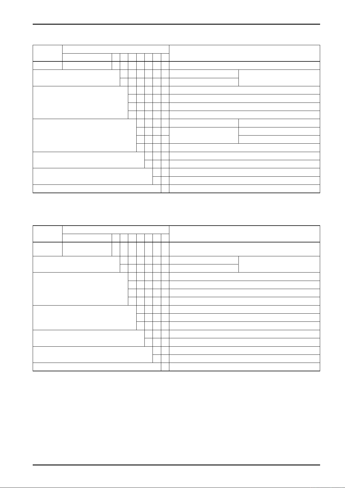
Table 5.3 EL4321 Product Code Explanation
E-886-2-E
Item
Model E L 4 3 2 1
Power
Temperature Input
Density/pressure Input
Analog Output
Communication Capability
Finish 1
① ② ③ ④ ⑤ ⑥ − ⑦ ⑧ ⑨ ⑩ ⑪ ⑫
Product Code
6
7 85 to 264VAC, 50/60Hz
0 None
1 Pt 100Ω at 0°C
2
9
0
1 4 to 20mA/1 to 5V
9 Other than above (special)
1 Density (corrected for temperature and pressure)
9
0
1
Description
Density Computer (for spool densitometer for gas service)
20 to 30VDC
4 to 20mADC/1 to 5VDC
Other than above (special)
Density input Pressure input
Densitometer type:
DG○ (gas service)
Other than above (special)
No
Yes
Munsell N1.5
Power consumption: 20W max.
None (fixed value)
Table 5.4 EL4331 Product Code Explanation
Item
Model E L 4 3 3 1
Power
Temperature Input
Density Input
Analog Output
Communication Capability
Finish 1
① ② ③ ④ ⑤ ⑥ − ⑦ ⑧ ⑨ ⑩ ⑪ ⑫
Product Code
6 20 to 30VDC
7
0 None
1 Pt 100Ω at 0°C
2 4 to 20mADC/1 to 5VDC
9 Other than above (special)
2 Densitometer: FD700 for liquid service
3 Densitometer: FD800 for liquid service
9
1 Corrected density
9 Other than above (special)
0 No
1
Description
Density Computer
(for spool densitometer for liquid service)
85 to 264VAC, 50/60Hz
Other than above (special)
Yes
Munsell N1.5
Power consumption: 20W max.
11
Page 12
E-886-2-E
MO DE L
EL4001
RUN
6. INTERNAL COMPONENTS AND FUNCTIONS
6.1 Front Panel
6.1.1 Display
The display is a 128 × 128-dot multiple function display capable of showing the data, units of measure,
error messages, and other information at the same time. (The display is backlighted.)
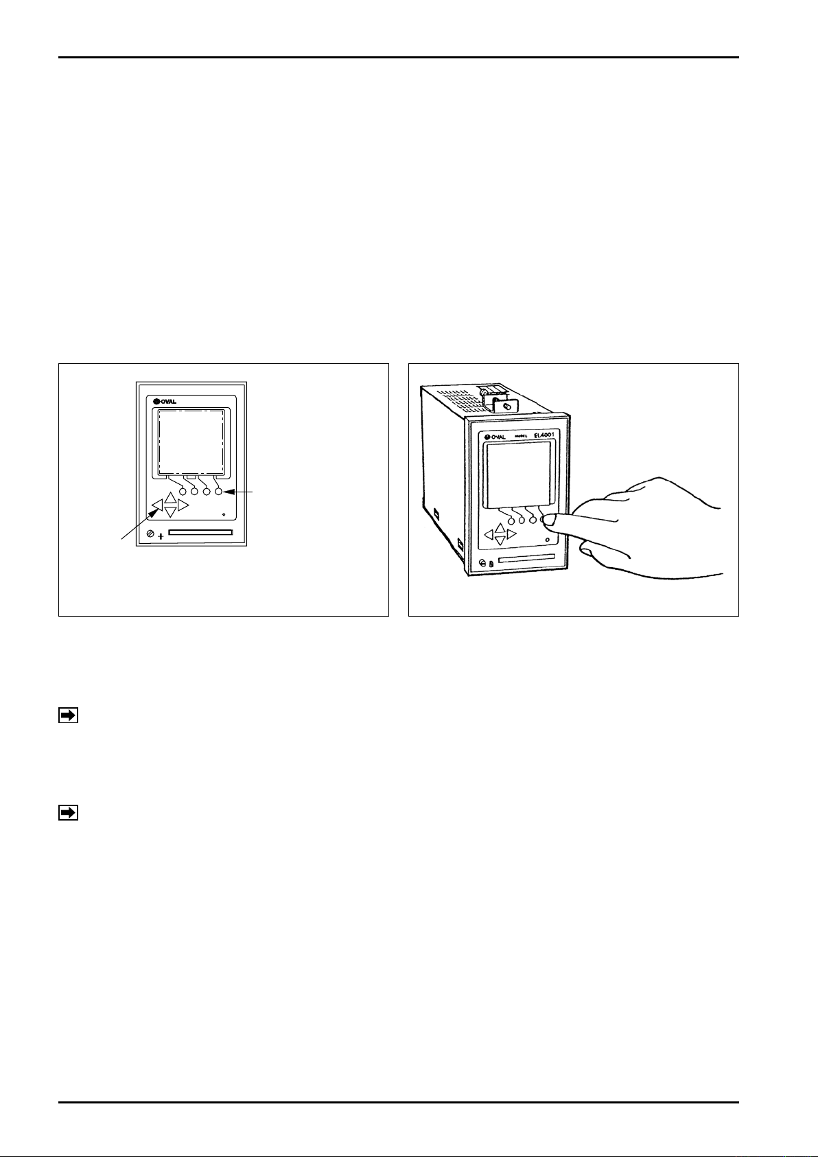
6.1.2 Front Panel Keypad
The eight front panel key switches consist of two kinds of keys - functions keys and shift keys.
・Function keys: Four round keys
Mainly used for function selection, such as activating the input conditions selected and reconfiguration.
・Shift keys: Four triangular keys
Used for moving the cursor, moving between menu items, or changing numerical values.
Function Keys
Shift Keys
Fig. 6.1 Front Panel Keys
Fig. 6.2 Touch Key Operation
6.1.3 Error Messages
When an erratic condition arises, an error message automatically appears on the display.
NOTE: The information represented by error messages are listed on page 19.)
If two or more concurrent errors are involved, individual messages will be scrolled at intervals
of approximately 3 seconds. When an error condition disappears, an error message automatically goes out and the normal display is resumed.
NOTE: An error logging function can store a maximum of 20 events each of which consists of year,
month, day, hour and minutes of error occurrence and recovery.
(⇒Complete details are covered in the Key Operation Manual.)
1
Page 13
E-886-2-E
6.1.4 Display Items
The units of measure vary with instrument programming. You select the units of measure in the SET
mode.
NOTE: For complete details, see the Key Operation Manual.
The information displayed (menu items) by model are described below (Tables 6.1 through 6.4).
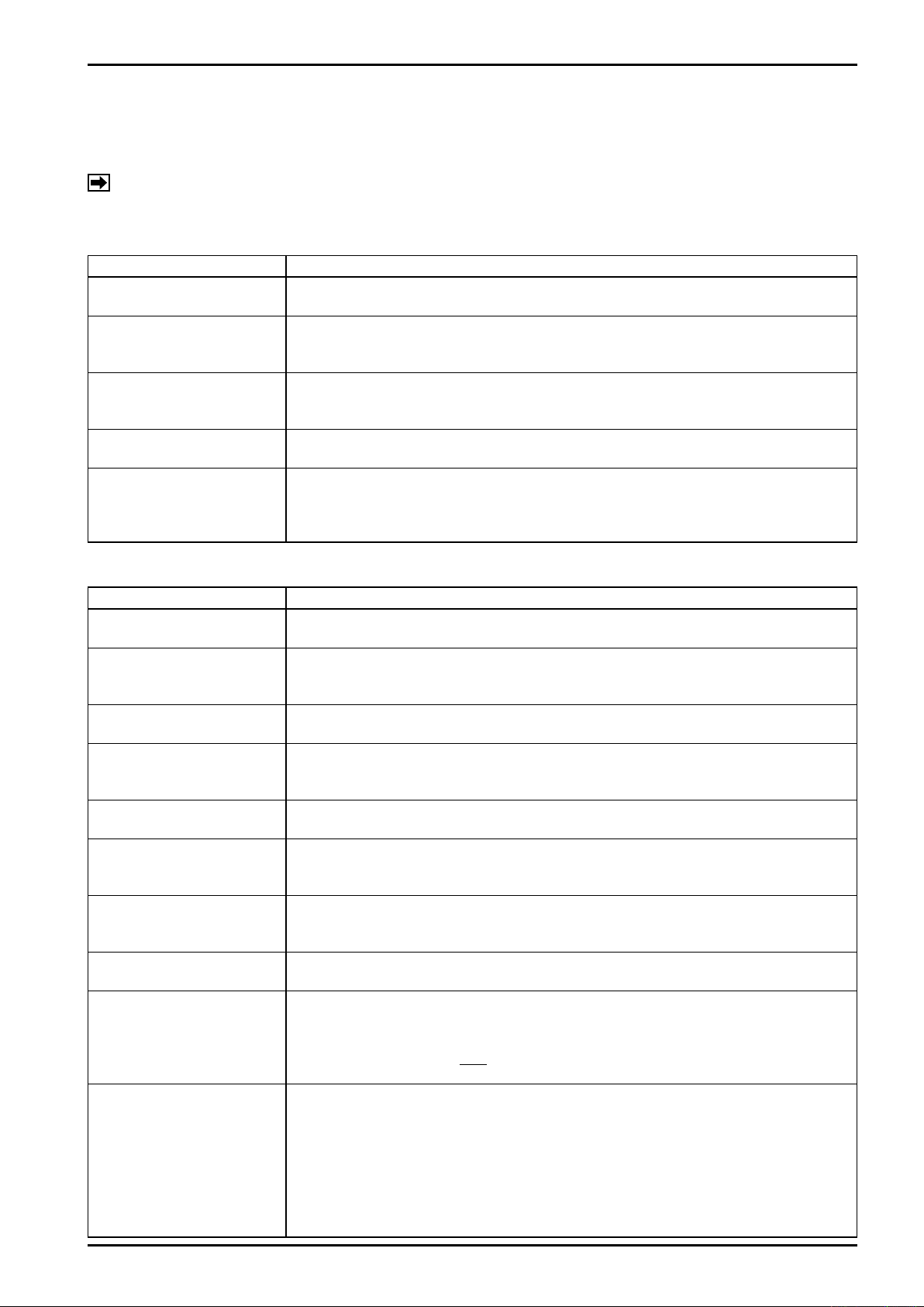
Table 6.1 EL4301 Display Items
Display Item Description
Density Before Correction
(DENSITY)
Corrected Density
(DENSITY(C))
Temperature
(TEMPERATURE)
Density Period
(DENSITY PERIOD)
Weight Concentration of Solid
(%MASS)
Calculates density from density periods of the flowmeter and displays it.
Calculates density at reference temperature using the thermal expansion coefficient of
the fluid and displays it. If it exceeds preset high or low limit, its default fallback value is
shown.
Displays surface temperature of flowmeter sensor tubes.
In most cases it remains the same as that of the fluid. But if ambient temperature differs
noticeably from fluid temperature, it may not agree with fluid temperature.
Displays oscillating period of flowmeter sensor tubes which varies with fluid density. If
the period exceeds 25 ms, "99999.999" is shown.
Displays concentration of solids in slurries in terms of weight, based on corrected
density. Some liquids in which solids dissolve may result in inaccurate readings. Take
aqueous solution of caustic soda and sugared water, for example. They change volume
as they dissolve and may possibly result in inaccurate concentration readings.
Display Item Description
Density Before Correction
(DENSITY)
Corrected Density
(DENSITY(C))
Total Mass Flowrate
(TOTAL COUNT)
Total Mass Flow of Solid
Content
(TOTAL COUNT(SOLID))
Instant Mass Flowrate
(FLOW RATE)
Instant Mass Flow of Solid
Content
(FLOW RATE(SOLID))
Temperature
(TEMPERATURE)
Density Period
(DENSITY PERIOD)
Meter Error Correction
Factor
(METER ERROR)
Proportion of Solids Content
(SOLID RATIO)
Table 6.2 EL4311 Display Items
Calculates density from oscillation periods of flowmeter tubes and displays it.
Calculates density at reference temperature using the thermal expansion coefficient of
the fluid and displays it. If it exceeds preset high or low limit, its default fallback value is
shown.
Displays mass flow corrected for meter error.
Calculates concentration of solids in slurries in terms of weight, based on density before
correction and, taking the obtained result into account, displays total flow of solids
content.
Displays instant mass flowrate, based on the mass flowrate corrected for meter error.
Calculates concentration of solids in slurries in terms of weight, based on density before
correction and, taking the obtained result into account, displays instant flowrate of
solids content.
Displays surface temperature of flowmeter sensor tubes.
In most cases it remains the same as that of the fluid. But if ambient temperature differs
noticeably from fluid temperature, it may not agree with fluid temperature.
Displays oscillating period of flowmeter sensor tubes which varies with fluid density. If
the period exceeds 25 ms, "99999.999" is shown.
Displays meter error correction factor relative to the flowrate information currently
coming in from the flowmeter. Based on this reading, mass total and instant mass flowrate are corrected for meter error.
E
[Reading] = 1 +
100
Displays proportion of solids content, based on current line temperature, density before
correction, and correction factor of the quadratic function of temperature and density.
(See "Total Flow of Solids Content" in Sec. 7.)
Based on the reading so obtained, total flow of solids content and instant flowrate of
solids content are calculated.
[Reading] = (Pa + Pb・Dx + Pc・Dx2)・(Ta + Tb・tx + Tc・tx2)
where tx: Line temperature Dx: Density before correction
Pa thru Pc, Ta thru Tc : Correction factors
1
Page 14
E-886-2-E
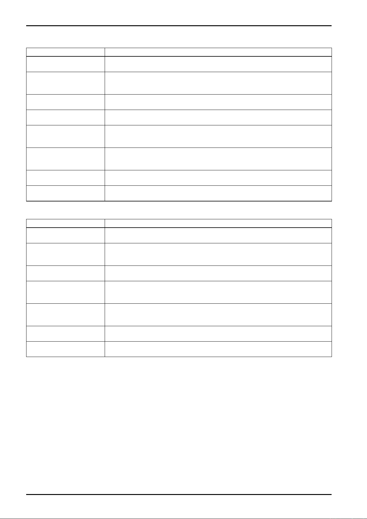
Display Item Description
Density Before Correction
(DENSITY)
Corrected Density
(DENSITY(C))
Density Period
(DENSITY PERIOD)
Correction Factor
(COMP. FACTOR)
Temperature
(TEMPERATURE)
Pressure
(PRESSURE)
Molecular Weight
(MOLECULAR WEIGHT)
Specific Weight
(SPECIFIC WEIGHT)
Table 6.3 EL4321 Display Items
Transforms density pulse periods currently being fed from the densitometer into a
density reading and displays it.
Displays density corrected for temperature and pressure.
If an error occurs in density conversion, such as out of range, its default fallback value
is displayed.
Displays pulse period currently coming in from the densitometer.
If the input exceeds 650μs or is missing, "999.999" is displayed.
Displays correction factor based on current temperature and pressure, and correction
factor X of a quadratic function of temperature and pressure.
Displays temperature value currently coming in.
If an error occurs in temperature conversion, such as out of range, its default fallback
value is displayed.
Displays pressure value currently coming in.
If an error occurs in pressure changes, such as out of range, its default fallback value is
displayed.
Calculates molecular weight, based on the temperature, pressure, and density currently
coming in, and displays it.
Calculates specific weight based on the temperature, pressure, and density currently
coming in, and displays it.
Display Item Description
Density Before Correction
(DENSITY)
Corrected Density
(DENSITY(C))
Density Period
(DENSITY PERIOD)
Temperature
(TEMPERATURE)
Pressure
(PRESSURE)
Molecular Weight
(MOLECULAR WEIGHT)
Specific Weight
(SPECIFIC WEIGHT)
Table 6.4 EL4331 Display Items
Transforms density pulse periods currently being fed from the densitometer into a
density reading and displays it.
Displays density corrected for temperature.
If an error occurs in density conversion, such as out of range, its default fallback value
is displayed.
Displays pulse period currently coming in from the densitometer.
If the input exceeds 650 μs or is missing, "999.999" is displayed.
Displays temperature value currently coming in.
If an error occurs in temperature conversion, such as out of range, its default fallback
value is displayed.
Displays pressure value currently coming in.
If an error occurs in pressure changes, such as out of range, its default fallback value is
displayed.
Calculates molecular weight, based on the temperature, pressure, and density currently
coming in, and displays it.
Calculates specific weight based on the temperature, pressure, and density currently
coming in, and displays it.
1
Page 15
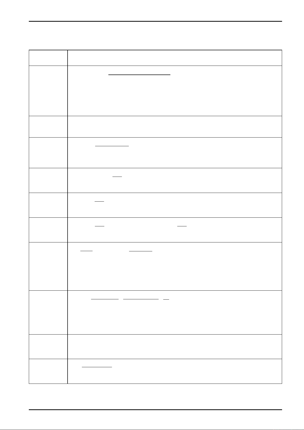
7. CALCULATION FORMULAS
E-886-2-E
Table 7.1
Calculate Item
(Models)
Tx2 (1-αtx) -Ta2 (1-αta)
Dx = (Dw - Da) {
Density before
correction
(EL4301)
(EL4311)
Corrected dens.
(EL4301)
(EL4311)
%MASS
(EL4301)
Total mass flow
(EL4311)
Total flow of sol-
ids content
(EL4311)
Tw2 (1-αtw) -Ta2 (1-αta)
Where Dw: Density of water[g/ml]
tw: Temperature of water during calibration[°C]
α: Temp. correction factor of tube spring const. [%/°C]
Tw: Density period of water[μs]
ta: Temperature of air during calibration[°C]
Dxc = Dx + β(tx - to)[g/ml]
where β:Thermal expansion coeff. of fluid[g/ml/°C] to: Ref. temp. for temp. correction[°C]
D4 (Dxc - D3)
%MASS =
Dxc (D4 - D3)
where D3: Density of carrier fluid[g/ml] for calculation of %MASS (others)
D4: Density of target fluid[g/ml]
E
Qu = a× Ip ÷ (1+ ) [kg]
100
where a: Meter factor[kg/P] Ip: Number of input pulses E: Meter error correction[%]
Xs
Qa = Qu× [kg] Xs = (Da + Db・Dx + Dc・Dx2) × (Ta + Tb・tx + Tc・tx2)[%]
100
where Xs: Solids proportion Da to Dc, Ta to Tc: Coefficients to determine Xs
×100[%]
Calculation Formula
) + Da[g/ml]
tx: Line temperature[°C]
Ta: Density period with air [μs]
Tx: Density period[μs]
Da: Density with air[g/ml]
Instant flowrate
of solids content
(EL4311)
Density before
correction
(EL4321)
(EL4331)
Corrected
density
(EL4321)
Corrected
density
(EL4331)
Analog output
(EL4321)
(EL4331)
Xs E
Qsr = Qr× [kg/h] Qr = a × f ÷ (1 ÷ ) × 3600 [kg/h]
100 100
where f: Input frequency[Hz] E: Meter factor correction[%]
2・do (T - To')
d = ・[(T - To') + K ] [g/l] To' = To + α (t - tcal)[μs]
To' 2To'
where T: Period time during meas.[μs] do: Constants Gas service: 70[g/l] ±10%
t: Line temperature[°C] Liquid service: 210[g/l] ±10%
To: Period time under vacuum Gas service: 350[μs] ±10%
Liquid service: 180[μs] ±10%
tcal Temperature during calib. [°C] α: Temperature coeff.[μs/°C] K: Constant
tx + 273.15 Po + 0.101325 1
dN = d・ ・ ・ [g/l]
to + 273.15 Px + 0.101325 X
X = (Pa + Pb・Px + Pc・Px2) × (Ta + Tb・tx + Tc・tx2)
where To: Reference temperature[°C] Tx: Temp. during measurement[°C]
Po: Reference pressure[MPa (gauge)] Px: Press. during meas. [MPa (gauge)]
X: Compressibility coeff. Pa to Pc, Ta to Tc: Factors to calculate compressibility coeff.
dN = d + β (tx - to)[g/l]
where
β: Thermal expansion coeff. of fluid[g/l/°C]
dN - dB
I = ( × 16) + 4[mA]
Density Span
where dB: Base density[g/L]
2
Continued on next page
1
Page 16
E-886-2-E
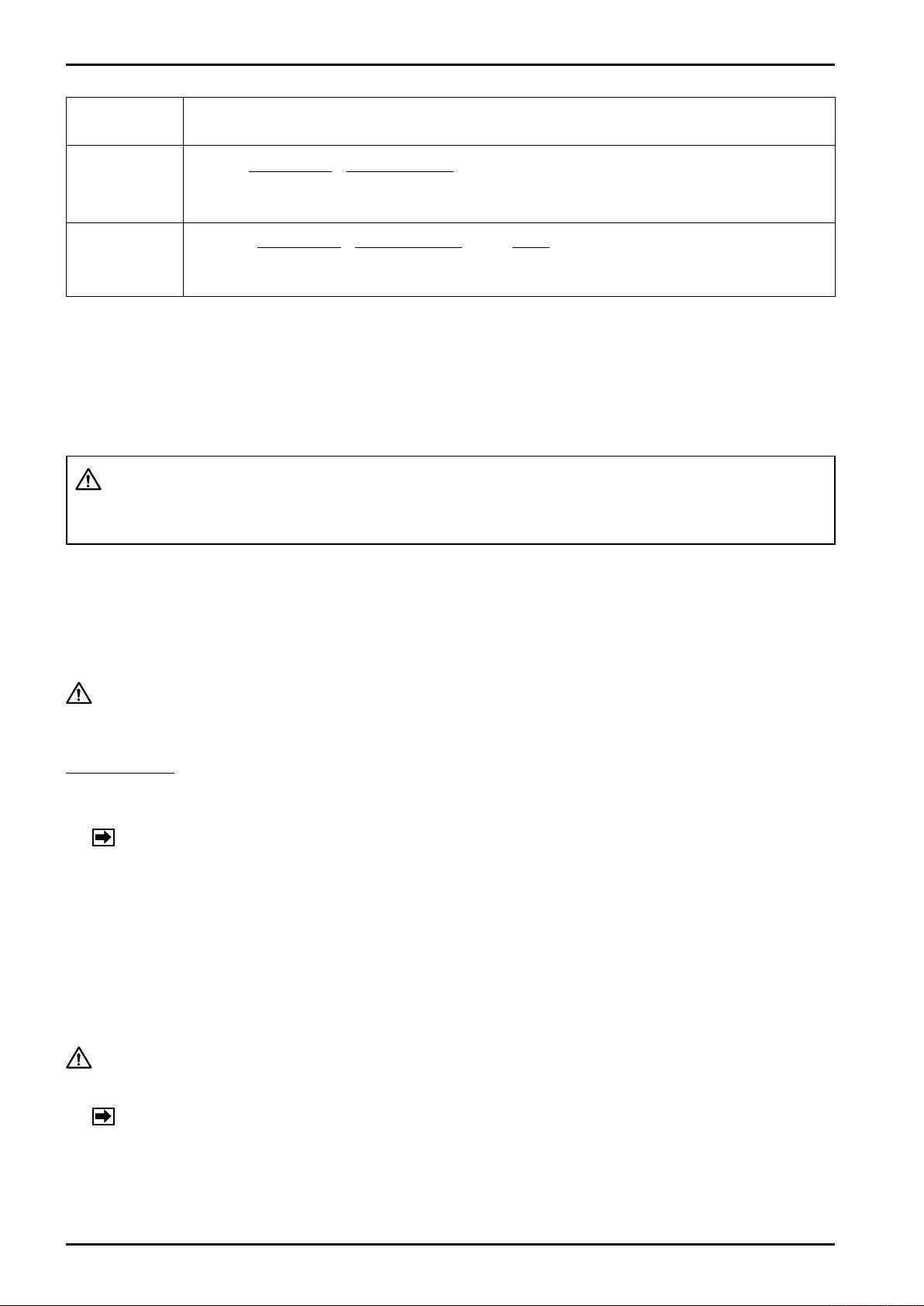
Calculate Item
(Models)
Molecular
weight
(EL4321)
Specific weight
(EL4321)
tx + 273.15 0.101325
M = d・ ・ ・1/X・MOL[g/mol]
273.15 Px + 0.101325
where MOL = Volume at 0°C and 1 atm. 22.4136[l]
tx + 273.15 0.101325 1
SG = d・ ・ ・1/X・
273.15 Px + 0.101325 RSG
where RSG = Density of air at 0°C and 1 atm. 1.293[g/l]
Calculation Formula
8. PREPARATIONAL CHECKS AND OPERATION
8.1 Preparation Before Operation
(1) Ensure that the instrument and related equipment are correctly installed and wired with no place left
unfinished.
WARNING: Make sure to see that the power terminals are connected to a power
source of the rated voltage. Applying a power source of incorrect voltage
could ruin your instrument.
(2) Supply power to this instrument and make certain to see that the front panel display is illuminated.
The display will remain unilluminated for one second after power on, which however is by no means
any indication of fault.
8.2 Preparational Checks
CAUTION: Allow a warmup period for 60 minutes or so after you turn on the power.
Verify if the instrument operates with no fluid flow.
How to Check
(1) Couple sources of simulated temperature and pressure signals.
(2) Using the shift keys, select menu items and verify the information displayed.
NOTE: See the KEY OPERATION MANUAL.
(3) Inject a simulated input pulse train or density signal representing the type of the companion pulse
generator.
(4) Select display menu items of the total count before correction and corrected total count, or the density
before correction and corrected density, and make sure that incoming pulses are being accumulated
or calculated. Also, verify that pulse output and analog output are properly generated.
(5) Compare the obtained readings on the display with corresponding theoretical values.
8.3 Operation
CAUTION: Allow a warmup period for 60 minutes or so after you turn on the power.
(1) Select your power reset or non-reset (accumulated total) option.
NOTE: See the KEY OPERATION MANUAL.
(2) Turn on power. While the initial check screen remains displayed, indicating that the process of veri-
fying parameters and variables is in progress after you turned on the power, your instrument will not
accept any pulse input.
(3) Place your instrument in service operation by allowing the fluid to be metered.
1
Page 17
E-886-2-E
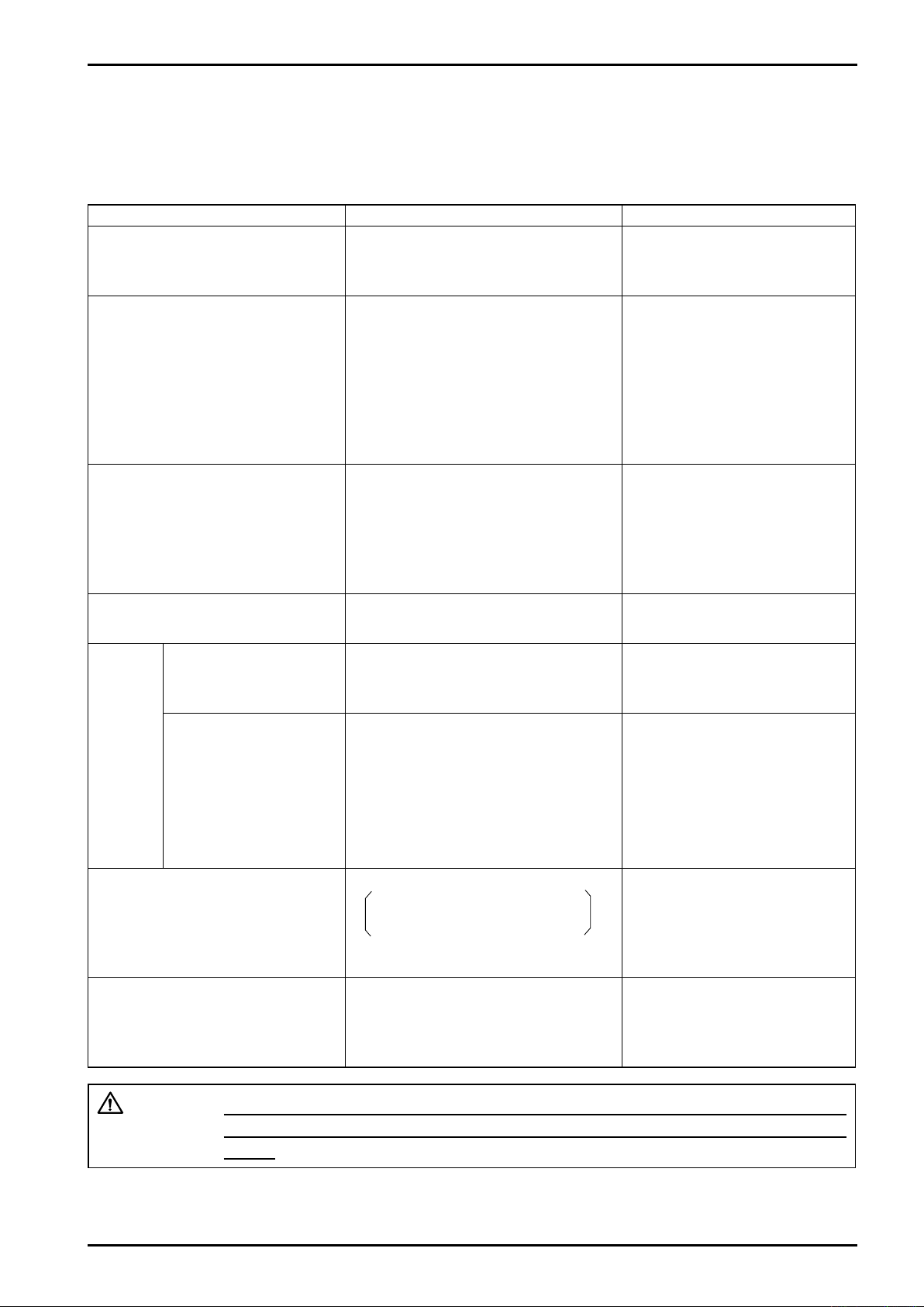
9. TROUBLESHOOTING
Reminder: If internal trouble is suspected, seek our service at the nearest sales office or cus-
tomer service representative in your area.
Table 9.1
Symptom Check Possible Causes
Display is dead. 1. Inspect fuse.
2. Make sure of power source volage.
1. Fuse is blown.
2. Line voltage is improper.
3. A fault in internal assembly.
Faulty temperature indication.
Erratic reading
Error messages
TEMP 1 (PT) OVER
or TEMP 1 (PT) UNDER
or TEMP 1 (ANA) OVER
or TEMP 1 (ANA) UNDER
(Same also with TEMP 2.)
Faulty pressure indication.
Erratic reading
Error messages
PRESS 1 OVER
or PRESS 1 UNDER
(Same also with PRESS 2.)
Faulty meter error correction factor
and/or temperature correction factor.
While
fluid is
allowed
to flow.
Fails to count pulses;
fails to produce a pulse
output.
Faulty total counter reading.
1. Input signal line correctly wired?
2. Input signal specifications matched?
3. System configured correctly?
4. Temperature range set correctly?
1. Input signal line correctly wired?
2. Input signal specifications matched?
3. System configured correctly?
4. Pressure range set correctly?
1. Temperature and pressure readings
correct?
1. Input signal line correctly wired?
2. Pulse signal coming in?
1. Pulse generator specifications
matched?
2. Temperature and pressure readings
correct?
3. Meter error and temperature/pressure
correction factors shown correct?
1. Input wiring is incorrect.
2. Thermometer resistance bulb is
open or shorted.
3. Temperature converter is faulty.
4. A fault in internal assembly.
1. Input wiring is faulty.
2. Pressure transmitter is faulty.
3. A fault in internal assembly.
1. A fault in internal assembly.
1. Incorrect input wiring.
2. Pulse generator itself is faulty.
1. A fault in internal assembly.
2. Pulse generator itself is faulty.
3. A fault in internal assembly.
Error messages
A/D CONVERT ERROR
or DENSITY CONVERT ERROR
or 4mA SCALER 1 UNDER
(Same also with SCALER 2.)
Error messages
DENSITY OVER
or DENSITY UNDER
or 20mA SCALE OVER
A fault in the internal assembly is
suspected. Seek our service.
1. System configured correctly?
2. Input pulse signal correct?
3. Flowrate full scale set properly?
1. A fault in internal assembly.
1. A fault in internal assembly.
CAUTION: Once any printed circuit board(s) of the internal assembly has been
removed for servicing, do not fail to reestablish all parameters in the SET
mode.
1
Page 18
E-886-2-E
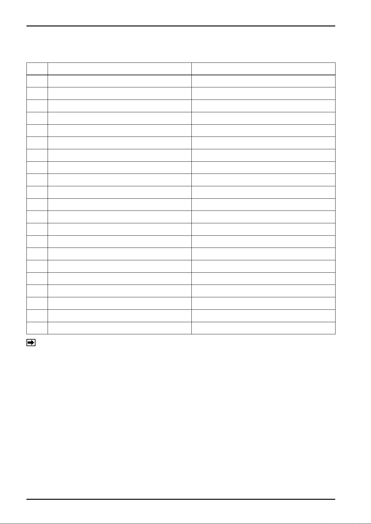
10. ERROR MESSAGES
Table 10.1 List of Error Messages
No. Error Message Description
1 ADJUST DATA ERROR Adjusted allowable range check error
12 A/D CONVERT ERROR A/D converter circuit error
13 DENSITY CONVERT ERROR Density converter circuit error
14 TEMP 1. (PT) OVER Temperature Pt input 1 overflow
15 TEMP 1. (PT) UNDER Temperature Pt input 1 underflow
16 TEMP 2. (PT) OVER Temperature Pt input 2 overflow
17 TEMP 2. (PT) UNDER Temperature Pt input 2 underflow
18 TEMP 1. (ANA) OVER Analog temperature input 1 overflow
19 TEMP 1. (ANA) UNDER Analog temperature input 1 underflow
20 TEMP 2. (ANA) OVER Analog temperature input 2 overflow
21 TEMP 2. (ANA) UNDER Analog temperature input 2 underflow
22 PRESS 1. OVER Analog pressure input 1 overflow
23 PRESS 1. UNDER Analog pressure input 1 underflow
24 PRESS 2. OVER Analog pressure input 2 overflow
25 PRESS 2. UNDER Analog pressure input 2 underflow
26 DENSITY OVER Density input overflow
27 DENSITY UNDER Density input underflow
28 4mA SCALER 1 UNDER Analog output 1 underflow
29 20mA SCALER 1 OVER Analog output 1 overflow
30 4mA SCALER 2 UNDER Analog output 2 underflow
31 20mA SCALER 2 OVER Analog output 2 overflow
NOTE: Depending on the model in service, some of the messages are not shown.
11. BEHAVIOR IN ERRATIC CONDITIONS
(1) Erratic A/D Converter
If, following energization of A/D converter circuit, the conversion process is not completed within the
specified time period, it is found that the circuit has a problem. At this point, temperature and pressure
fallback values are used for calculation.
(2) Temperature and Pressure Input Out of Range
If the input exceeds the high limit or falls below the low limit, its default fallback value is used for
calculation.
(3) Analog Output Overflow
A full scale output is produced across the analog output terminals.
1
Page 19
E-886-2-E
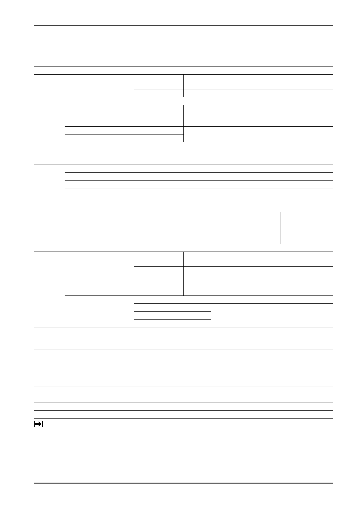
12. GENERAL SPECIFICATIONS
12.1 EL4301 Density Computer for Mass Flowmeter
Table 12.1
Item Description
Resist. thermo-
Input
signals
Output
signals
Display type
Menu
Items
Computing
range
Computing
accuracy
Clock IC backup battery Lithium battery Battery life: 10 years approx.
Communication (when communication
interface is provided)
Transmission cable
Power source 85 to 264VAC, 50/60Hz or 20 to 30VDC
Power consumption 20W max.
Ambient temperature -10 to +50°C
Mounting Panel mount
Finish Munsell N1.5
Weight 2.5 kilograms, approx.
NOTES
Temp. input
Density input Tube period signal (from L.H. sensor) ±5V square wave
Analog output
Alarm output 1 High alarm With respect to the density corrected for temperature
Alarm output 2 Low alarm
Alarm output 3 Static relay Capacity: 230VAC/340VDC 0.2A
Density before correction To the 4th decimal place (when g/ml is selected.)
Corrected density To the 4th decimal place (when g/ml is selected.)
Temperature To the 2nd decimal place (when °C is selected.)
Density period To the 1st decimal place (when μs is selected.)
% Mass To the 2nd decimal place
Error alarm Number of errors + error messages
Temperature
Density 0.0000 to 6.0000g/ml
ULTRA mass MKII
(CN series)
Temperature
meter bulb
Analog 4 to 20mADC or 1 to 5VDC, 10mV/°C, 5mV/°C
Corrected density
or concentration
(% mass)
Display: ST display (128×128 dots), backlighted (※1), (※2)
Information displayed: Data, units, error message simultaneously
Pt 100Ω at 0°C Range: -50 to +200°C
4 to 20mADC or 1 to 5VDC Range: -200 to +200°C
10mV/°C Range: -50 to +150°C
5mV/°C Range: -100 to +200°C
Density before
correction
Corrected density
Pt 100Ω at 0°C ±0.3% of span
4 to 20mADC or 1 to 5VDC
5mV/°C
Interface: RS485 Multipoint (Up to 16 units can be connected.)
Dedicated protocol Baud rate: 4800 bps standard 9600 bps max.
Use 3-conductor shielded cable to the resistance thermometer bulb.
Loop resist. 5Ω max. Example: 300 meters max. with 3-conductor 1.25mm2
cable; 500 meters with 2.0mm2 cable
(※1): ST display stands for Super Twisted Nematic display.
(※2): Backlight life (luminance declined to one half its original luminance): 2500 hours, approx.
(※3): Depends on the accuracies of temperature input and density expansion coefficient of the fluid
with respect to the uncorrected density.
(Accuracy is shown where density change is constant with respect to the difference between
the temperature input and reference temperature.)
Pt 100Ω at 0°C, 3-wire system Rated current 2mA
4 to 20mADC (Max. load resistance 500Ω) or
1 to 5VDC (Output impedance 250Ω)
Conversion accuracy: ±0.1% of F.S.
Static relay 230VAC/340VDC, 0.1A
Std. Span: 70°C
Std. Span: 200°C
±0.001g/ml (Factory calibration accuracy: Option)
±0.002g/ml (with 4 to 20mA or 1 to 5VDC temperature
input)
±0.006g/ml (with temperature input from Pt 100Ω at 0°C,
3-wire) (※3)
±0.1% of span10mV/°C
1
Page 20
E-886-2-E
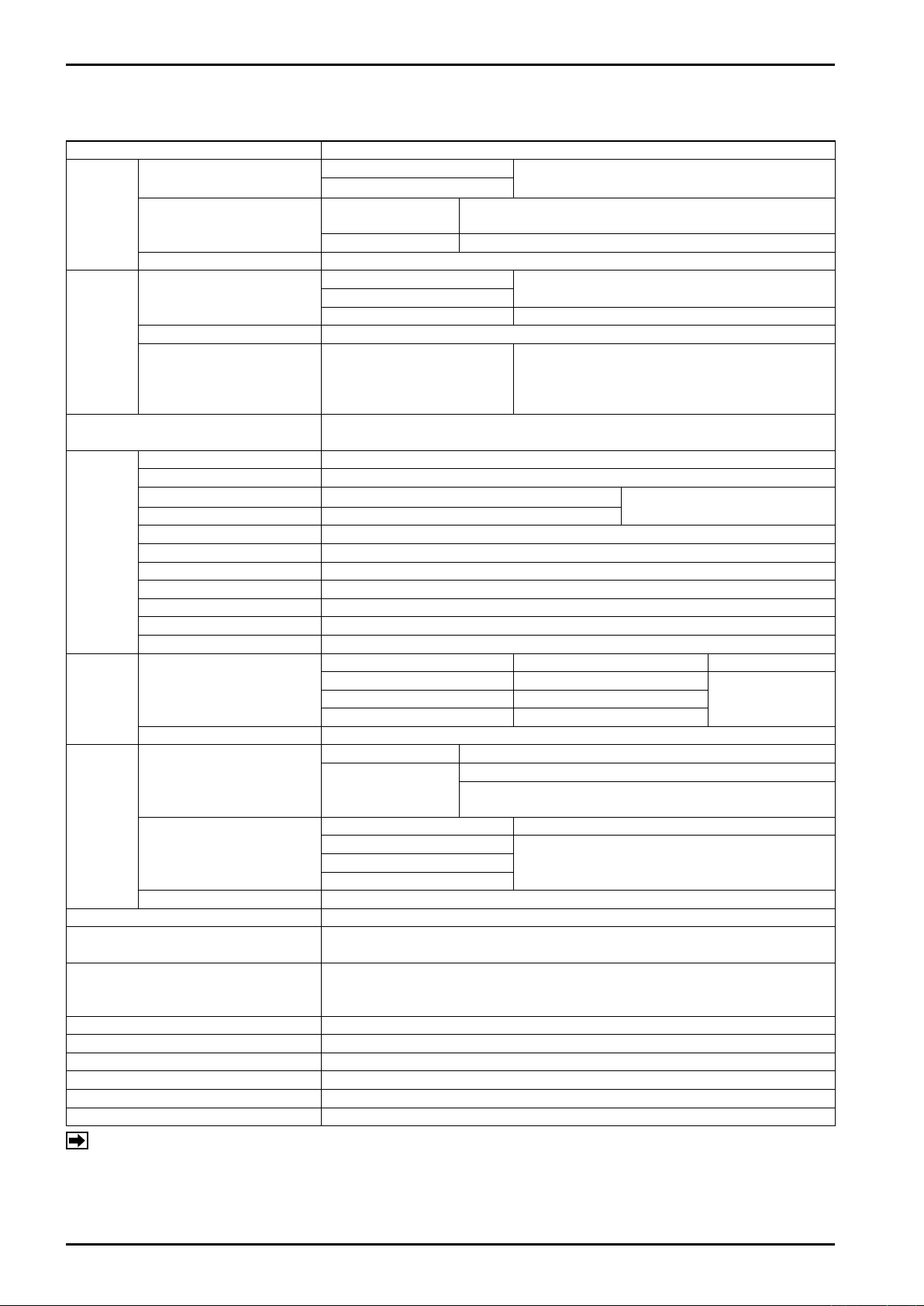
12.2
EL4311 Density Computer for Mass Flowmeter (with solids proportion calculation feature)
Table 12.2
Item Description
Flow input
Input
signals
Output
signals
Display type
Menu
Items
Computing
range
Computing
accuracy
Clock IC battery backup Lithium battery Battery life: 10 years approx.
Communication (when communication interface is provided.)
Transmission cable
Power source 85 to 264VAC, 50/60Hz or 20 to 30VDC
Power consumption 20W max.
Ambient temperature -10 to +50°C
Mounting Panel mount
Finish Munsell N1.5
Weight 2.5 kilograms, approx.
Temp. input
Density input Tube period signal (from L.H. sensor) ±5V square wave
Pulse output
Alarm output Static relay Capacity: 230VAC/340VDC 0.2A
Analog output
Density before correction To the 4th decimal place (g/ml, etc.)
Corrected density To the 4th decimal place (g/ml, etc.)
Total mass flow
Total mass flow of solid content
Instant mass flowrate kg/h, etc.
Instant mass flowrate of solid content
Temperature To the 2nd decimal place (when °C is selected.)
Density period To the 1st decimal place (when μs is selected.)
Meter error correct. factor To the 5th decimal place
Solids content proportion To the 2nd decimal place (%)
Error alarm Number of errors + error messages
Temperature
Density 0.0000 to 6.0000g/ml
ULTRA mass MKII
(CN series)
Temperature
Total flow of solids content ±0.2% of R.D.
NOTES (※1): ST display stands for Super Twisted Nematic display.
(※2): Backlight life (luminance declined to one half its original luminance): 2500 hours, approx.
(※3): Depends on the accuracies of temperature input and density expansion coefficient of the fluid
to the uncorrected density. (Accuracy is shown where density change is constant to the difference between the temperature input and reference temperature.)
2-wire voltage pulse
Open collector pulse
Resist. thermometer bulb
Analog 4 to 20mADC or 1 to 5VDC, 10mV/°C, 5mV/°C
Total mass flow
Total solids content
Output sync with flow input Open collector pulse
Instant mass flow
Instant solids content rate
Solids proportion or
corrected density
Display: ST display (128×128 dots), backlighted (※1), (※2)
Information displayed: Data, units, error message simultaneously
Same as the output pulse unit (kg, etc.)
Same as the output pulse unit (kg, etc.)
kg/h, etc.
Pt 100Ω at 0°C Range: -50 to +200°C Std. span: 70°C
4 to 20mADC or 1 to 5VDC Range: -200 to +200°C
5mV/°C Range: -100 to +200°C
Density before corr. ±0.001g/ml (Factory calib. accuracy: Option)
Corrected density
Pt 100Ω at 0°C ±0.3%
4 to 20mADC or 1 to 5VDC
5mV/°C
Interface: RS485 Multipoint (Up to 16 units can be connected.)
Dedicated protocol Baud rate: 4800 bps standard 9600 bps max.
Use 3-conductor shielded cable to the resistance thermometer bulb.
Loop resist. 5Ω max. Example: 300 meters max. with 3-conductor 1.25mm2
cable; 500 meters with 2.0mm2 cable
Pt 100Ω at 0°C, 3-wire system Rated current 2mA
±0.002g/ml (with 4 to 20mA or 1 to 5VDC temp. input)
±0.006g/ml (with temp. input from Pt 100Ω at 0°C,
3-wire) (※3)
Speed of response 2kHz
Static relay Capacity: 230AC/340VDC 0.2A
Pulse width: 1ms/50ms
4 to 20mADC (Max. load resistance 500Ω)
or 1 to 5VDC (Output impedance 250Ω)
Conversion accuracy: ±0.1% of F.S.
Count capacity: 8 digits
Std. span: 200°C10mV/°C Range: -50 to +150°C
±0.1% of span10mV/°C
0
Page 21
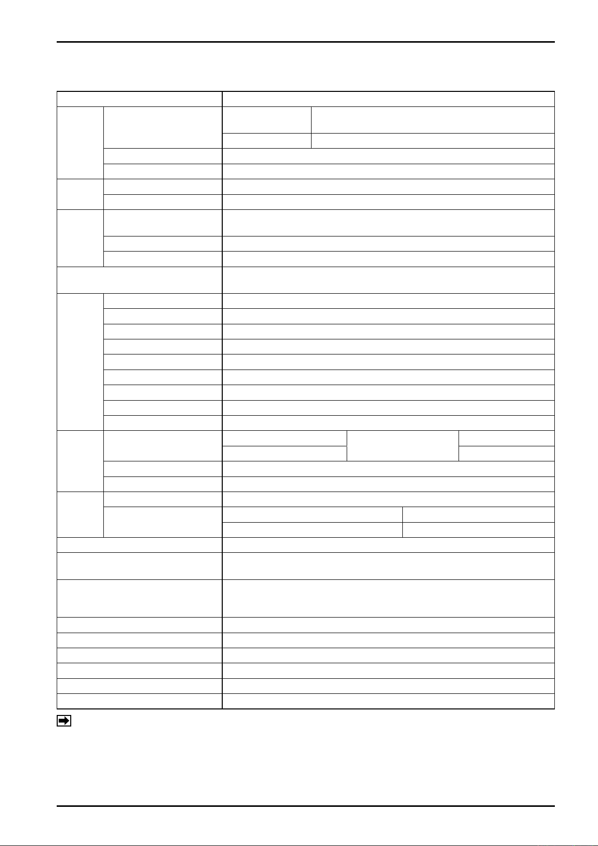
12.3 EL4321 Density Computer for Spool Densitometer (gas service)
Table 12.3
Item Description
Resistance thermo-
Input
signals
Supply
power
Output
signals
Display type
Menu
Items
Computing
range
Computing
accuracy
Clock IC battery backup Lithium battery Battery life: 10 years approx.
Communication (when communication interface is provided.)
Transmission cable
Power source 85 to 264VAC, 50/60Hz or 20 to 30VDC
Power consumption 20W max.
Ambient temperature -10 to +50°C
Mounting Panel mount
Finish Munsell N1.5
Weight 2.5 kilograms, approx.
Temperature input
Pressure input 4 to 20mADC or 1 to 5VDC
Density input Density period signal Pulse period 162 to 650μs
To densitometer preamp 28VDC 30mA
To pressure transmitter 24VDC 30mA max.
Corrected density
Alarm output Static relay Capacity: 230VAC/340VDC 0.2A
Conversion accuracy ±0.2% of span ±0.06g/l
Density before correction To the 3rd decimal place (when g/l is selected.)
Corrected density To the 3rd decimal place (when g/l is selected.)
Density period To the 3rd decimal place (when μs is selected.)
Correction factor To the 5th decimal place
Temperature To the 2nd decimal place (when °C is selected.)
Pressure To the 4th decimal place (when MPa is selected.)
Molecular weight To the 3rd decimal place (when g/mol is selected.)
Specific weight To the 3rd decimal place
Error alarm Number of errors + error messages
Temperature
Pressure 0 to 3MPa Standard span 1/2Pmax. to Pmax, 1/5Pmax. to Pmax.
Density 0 to 60g/l
Corrected density ±0.1% of span ± 0.006g/l
Temperature
meter bulb
Analog 4 to 20mADC or 1 to 5VDC
4 to 20mADC (Max. load resistance 500Ω) or 1 to 5VDC (Output impedance
250Ω) Conversion accuracy: ±0.1% of F.S.
Display: ST display (128×128 dots), backlighted (※1), (※2)
Information displayed: Data, units, error message simultaneously
Pt 100Ω at 0℃
4 to 20mADC or 1 to 5VDC Std. Span:200℃
Pt 100Ω at 0℃ ±0.3% of span
4 to 20mADC or 1 to 5VDC ±0.1% of span
Interface: RS485 Multipoint (Up to 16 units can be connected.)
Dedicated protocol Baud rate: 4800 bps standard 9600 bps max.
Use 3-conductor shielded cable to the resistance thermometer bulb.
Loop resist. 5Ω max. Example: 300 meters max. with 3-conductor 1.25mm2
cable; 500 meters with 2.0mm2 cable
Pt 100Ω at 0°C, 3-wire system Rated current 2mA
Range: -20 to 75℃
Std. Span: 70℃
E-886-2-E
NOTES (※1): ST display stands for Super Twisted Nematic display.
(※2): Backlight life (luminance declined to one half its original luminance): 2500 hours, approx.
1
Page 22
E-886-2-E
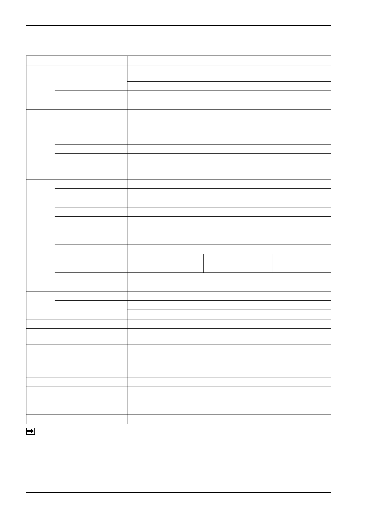
12.4 EL4331 Density Computer for Spool Densitometer (liquid service)
Table 12.4
Item Description
Resistance thermo-
Input
signals
Supply
power
Output
signals
Display type
Menu
Items
Computing
range
Computing
accuracy
Clock IC battery backup Lithium battery Battery life: 10 years approx.
Communication (when communication interface is provided.)
Transmission cable
Power source 85 to 264VAC, 50/60Hz or 20 to 30VDC
Power consumption 20W max.
Ambient temperature -10 to +50°C
Mounting Panel mount
Finish Munsell N1.5
Weight 2.5 kilograms, approx.
Temperature input
Pressure input 4 to 20mADC or 1 to 5VDC
Density input Density period signal Pulse period 162 to 650μs
To densitometer preamp 28VDC 30mA
To pressure transmitter 24VDC 30mA max.
Corrected density
Alarm output Static relay Capacity: 230VAC/340VDC 0.2A
Conversion accuracy ±0.2% of span ±0.06g/l
Density before correction To the 3rd decimal place (when g/l is selected.)
Corrected density To the 3rd decimal place (when g/l is selected.)
Density period To the 3rd decimal place (when μs is selected.)
Temperature To the 2nd decimal place (when °C is selected.)
Pressure To the 4th decimal place (when MPa is selected.)
Molecular weight To the 3rd decimal place (when g/mol is selected.)
Specific weight To the 3rd decimal place
Error alarm Number of errors + error messages
Temperature
Pressure 0 to 3MPa Standard span 1/2Pmax. to Pmax, 1/5Pmax. to Pmax.
Density 0 to 60g/l
Corrected density ±0.1% of span ± 0.006g/l
Temperature
meter bulb
Analog 4 to 20mADC or 1 to 5VDC
4 to 20mADC (Max. load resistance 500Ω) or 1 to 5VDC (Output impedance
250Ω) Conversion accuracy: ±0.1% of F.S.
Display: ST display (128 × 128 dots), backlighted (※1), (※2)
Information displayed: Data, units, error message simultaneously
Pt 100Ω at 0℃
4 to 20mADC or 1 to 5VDC Std. Span:200℃
Pt 100Ω at 0℃ ±0.3% of span
4 to 20mADC or 1 to 5VDC ±0.1% of span
Interface: RS485 Multipoint (Up to 16 units can be connected.)
Dedicated protocol Baud rate: 4800 bps standard 9600 bps max.
Use 3-conductor shielded cable to the resistance thermometer bulb.
Loop resist. 5Ω max. Example: 300 meters max. with 3-conductor 1.25mm2
cable; 500 meters with 2.0mm2 cable
Pt 100Ω at 0°C, 3-wire system Rated current 2mA
Range: -20 to 75°C
Std. Span: 70℃
NOTES (※1): ST display stands for Super Twisted Nematic display.
(※2): Backlight life (luminance declined to one half its original luminance): 2500 hours, approx.
Page 23
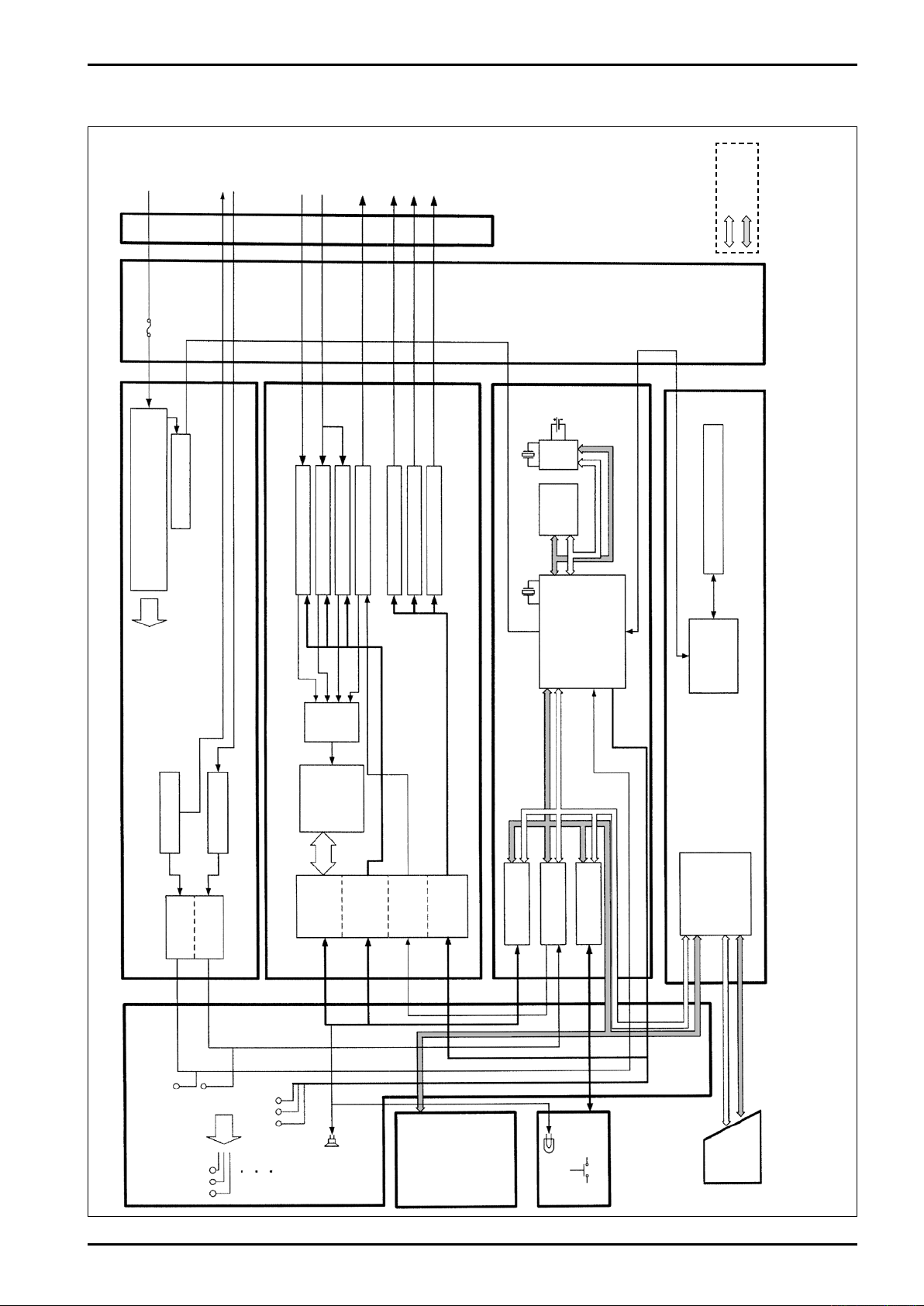
13. OVERALL BLOCK DIAGRAM
E-886-2-E
Power
Fuse
Power Unit
1/1 output
Density input
Power Board
Power Detect
Press. input
Temp. input
Analog output
Pulse output 1
Pulse output 2
Pulse output 3
Address path
Data path
Terminal
Block
32.768kHz
Real Time
Clock
Lithium
I/O Board
Press. Input Ckt. (analog)
Temp. Input Ckt. (analog)
Temp. Input Ckt. (Pt)
Analog Output Circuit
Pulse Output Circuit 1
Pulse Output Circuit 2
Pulse Output Circuit 3
Battery
CPU Board
Memory
20MHz
Communication Board Interface Board
CPU
Internal
Power
Multi
plexer
Isolation RS485
Fig. 13.1 Overall Block Diagram
A/D
Converter
Flow Input Ckt.
Dens. Input Ckt.
Circuit
IC Card
Isolation
Isolation
Isolation
Isolation
Isolation
Isolation
Parallel I/O
Timer Counter
Parallel I/O
Interface
Test Pins
Internal
Volt.
Buzzer
Test Pins
Motherboard
128×128 dots
ST Display
×8 keys
RUN
Keyboard
IC Card
Page 24

E-886-2-E
All specifications are subject to change without notice for improvement.
2017.01 Revised
2008.08 Released
E-886-2-E (1)
 Loading...