

Oval EL4301, EL4321, EL4331, EL4311 Instructions Manual
Ins. No. E-886-2-E
DENSITY COMPUTER
Model EL4301: Density Computer for Mass Flowmeter
Model EL4311: Density Computer for Mass Flowmeter
(with solids proportion calculation feature)
Model EL4321: Density Computer for Spool Densitometer
(gas service)
Model EL4331: Density Computer for Spool Densitometer
(liquid service)
This manual has been prepared to provide you with the information pertinent to the DENSITY
COMPUTERS. These models have the description in common except where noted.
With the proper application of the information and knowledge contained in this manual, you can
expect the best possible results over a long service life of these instruments. Keep this manual for
ready reference.
It is suggested that the instruction manuals for the companion pulse generator (flowmeter) and
receiving instrument be referred to at the same time.
1

E-886-2-E
TABLE OF CONTENTS
Page
1. BEFORE YOU BEGIN ............................................................................................................ 4
1.1 Confirming the Nameplate .................................................................................................... 4
1.2 Transportation Precautions ...................................................................................................4
1.3 Storage Precautions ............................................................................................................. 4
2. GENERAL ................................................................................................................................ 5
2.1 Features ................................................................................................................................5
2.2 Part Names ........................................................................................................................... 5
3. INSTALLATION ....................................................................................................................... 6
3.1 Outline Dimensions ...............................................................................................................6
3.2 Installation .............................................................................................................................6
3.2.1 Installation Location ........................................................................................................6
3.2.2 Panel ..............................................................................................................................6
3.2.3 Installation ......................................................................................................................6
4. WIRING .....................................................................................................................................7
4.1 Field Wiring Cables ...............................................................................................................7
4.2 Wiring Connections ...............................................................................................................7
4.3 Description of Terminal Blocks for External Connections .....................................................7
4.3.1 Terminal Identification ..................................................................................................... 8
5. PRODUCT CODE EXPLANATION ................................................................................... 10
6. INTERNAL COMPONENTS AND FUNCTIONS .............................................................12
6.1 Front Panel ......................................................................................................................... 12
6.1.1 Display ..........................................................................................................................12
6.1.2 Front Panel Keypad ......................................................................................................12
6.1.3 Error Messages ............................................................................................................ 12
6.1.4 Display Items ................................................................................................................ 13
7. CALCULATION FORMULAS .............................................................................................15
8. PREPARATIONAL CHECKS AND OPERATION ........................................................... 17
8.1 Preparation Before Operation ............................................................................................. 17
8.2 Preparational Checks ......................................................................................................... 17
8.3 Operation ............................................................................................................................ 17
9. TROUBLESHOOTING ......................................................................................................... 18
10. ERROR MESSAGES............................................................................................................19
11. BEHAVIOR IN ERRATIC CONDITIONS .......................................................................... 19
12. GENERAL SPECIFICATIONS ...........................................................................................20
12.1 EL4301 Density Computer for Mass Flowmeter ............................................................... 20
12.2 EL4311 Density Computer for Mass Flowmeter
(with solids proportion flowrate calculation feature) .......................................................... 21
12.3 EL4321 Density Computer for Spool Densitometer (gas service) .................................... 22
12.4 EL4331 Density Computer for Spool Densitometer (liquid service) .................................. 23
13. OVERALL BLOCK DIAGRAM ...........................................................................................24

E-886-2-E
COMPANION VOLUME
KEY OPERATION MANUAL Ins. No. E-880TM-E
CONTENTS
1. KEY ARRANGEMENT .........................................................................................................10
2. DISPLAY SCREEN ............................................................................................................... 11
3. INITIAL CHECK ..................................................................................................................... 14
4. MODE SELECTION ..............................................................................................................18
5. RUN MODE SCREEN .......................................................................................................... 23
6. SET MODE ............................................................................................................................. 36
7. SYS MODE ..........................................................................................................................142
8. ABOUT EL4401 ................................................................................................................... 170
9. ABOUT EL4501 ................................................................................................................... 175
10. DIP SWITCH CONFIGURATION ..................................................................................... 182
(※: Model with communication capabilities)
COMMUNICATION MANUAL (※) Ins. No. E-880CM-E
CONTENTS
1. COMMUNICATION CAPABILITY OVERVIEW .................................................................. 5
2. NETWORK CONFIGURATION ............................................................................................5
3. MODE SELECTION ................................................................................................................6
4. LOCAL / REMOTE SELECTION .......................................................................................... 8
5. SETUP ITEMS FOR COMMUNICATION ......................................................................... 10
6. COMMUNICATION PROCEDURE .................................................................................... 11
7. COMMUNICATION FORMAT .............................................................................................12
8. BCC / SUM CHECK ..............................................................................................................45
9. CR / LF ....................................................................................................................................46
10. CODES ASSIGNED TO UNITS ..........................................................................................48
11. ASCII CODE ...........................................................................................................................49

E-886-2-E
1. BEFORE YOU BEGIN
Every OVAL product is thoroughly tested and inspected before shipment from our factory.
When received, its appearance should be inspected for possible damage by rough handling during transit. First of all, thoroughly read the handling precautions described in this section. For topics other than
those covered in this section, refer to the respective sections of this manual.
If at any time in the future you seek our assistance, contact the nearest sales office in your area.
1.1 Confirming the Nameplate
The instrument is adjusted to individual specifications before shipment from our factory. Model
number appears on the nameplate attached to the
top of the housing.
Make sure to see that the instrument you received
conforms to the General Specifications (pages 21
through 24) and the Product Code Explanation
(pages 10 and 11).
※
Nameplate
(model number)
※EL4001 is the
generic designation of the
◆ When you inquire, supply complete infor-
EL4001 series
computers.
mation as to the product name, model
number, product number, ratings, and
Fig. 1.1 Nameplate Location
other pertinent information.
1.2 Transportation Precautions
(1) In order to safeguard against damage during transit, transport your instrument to the installation loca-
tion in the original package used for shipment from the factory if possible.
(2) Use care to avoid impact shocks to the instrument during transit.
1.3 Storage Precautions
If the instrument upon receipt is to be stored for extended periods of time before installation, unexpected
problems could arise. If such is the case, the following considerations should be taken:
(1) The instrument can best be stored in the original package used for transit from the factory.
(2) The place of storage should meet the following requirements:
☆ Free from rain and water
☆ Free from vibration and impact shocks
☆ With minimal temperature and humidity variation (around 25°C and 65% R.H.)
MODEL
EL4001
TB
1
TB
2
TB
1
TB
2
TB
3
PLS OUT3 TEMP IN TEMP IN FLOW IN
0V
+− B bA+−
+−+− +−
+−
SIG SUP
SUP
ANA OUTGND POWER
N
(
−
)
H
(
+
)
PRESS INPLS OUT1PLS OUT2
1/1
OUT
E-886-2-E
2. GENERAL
In comparison with the previously offered instruments (OVAL EL4080 series), substantial reduction in
physical geometry, improved functions and ease of operation have been achieved. Included among the
improvements in this newly developed instrument are simplified parameter changes and data logging with
IC cards along with a large, easy-to-read LCD display.
Table 2.1
Model Description
This instrument receives tube oscillation signal and temperature signal from the OVAL
EL4301
EL4311
EL4321
EL4331
Coriolis flowmeter and, upon calucation, displays the density of process fluid.
It also can display the density corrected for reference temperature and provide an analog
output.
This instrument receives mass flow signal and temperature/density signals from the OVAL
Coriolis flowmeter and, upon calucation, displays the total flow of solids content of process
fluid that contains solids.
It also can display the density corrected for reference temperature and provide an analog
output.
This instrument receives density frequency signal from the density sensor and provides
an analog output in proportion to the density of metered process fluid. In response to temperature and pressure signals (EL4321 only), it also can provide an output corrected for
reference conditions.
2.1 Features
(1) Performs calculation of density corrected for temperature.
(2) Changing the ranges of density, temperature, pressure, or other parameters, of the companion densi-
tometer is simple by keystrokes on the front-panel keypad or by inserting an IC card into the slot.
(3) A built-in CPU offers a high degree of performance and accuracy.
(4) Variables such as temperature, pressure, and density can be reviewed on command with the front
panel keypad, whether or not computation is in progress.
(5) A nonvolatile memory (E2PROM) retains all parameters in the event of an AC power failure.
(6) Displays the percent concentration of solids content in the slurries and provides its analog output
(EL4301 only).
(7) Produces high and low density alarm outputs (set to desired limits) (EL4301 only).
(8) If an error occurs, its nature is identified as an error message on the display.
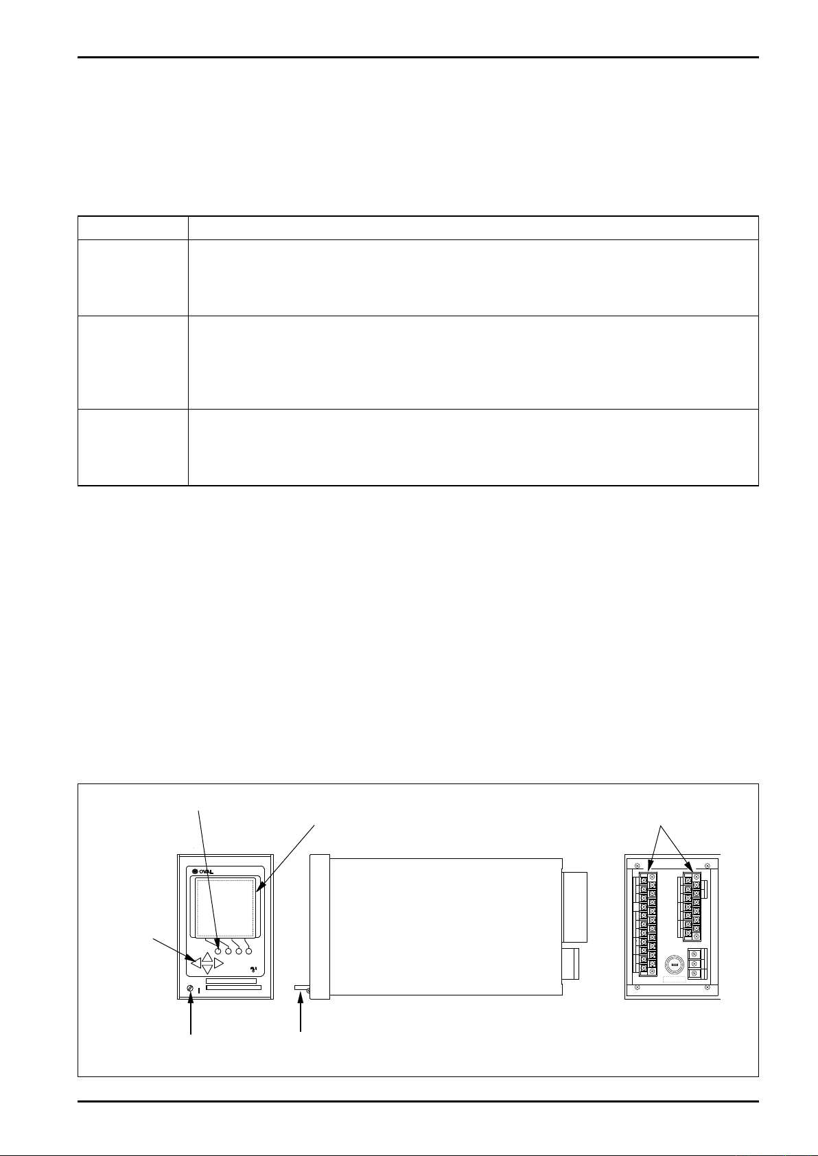
2.2 Part Names and Functions
Function Keys
Display
Terminal Blocks
Shift Keys
Seal Screw
IC Card (option)
Fig. 2.1 Part Names
TB
1
TB
2
TB
1
TB
2
TB
3
PLS OUT3 TEMP IN TEMP IN FLOW IN
0V
+− B bA+−
+−+− +−
+−
SIG SUP
SUP
PLS OUT2GND POWER
N
(
−
)
H
(
+
)
PRESS INANA
PLS OUT1
1/1
OUT
MODEL
EL4001
912596
20 232.4
144
136
E-886-2-E
Optimum
Range
600
1800
450 Acceptable Range
2200
Computer
Min.120
Min.220
92
±0.8
0
+1
138 0
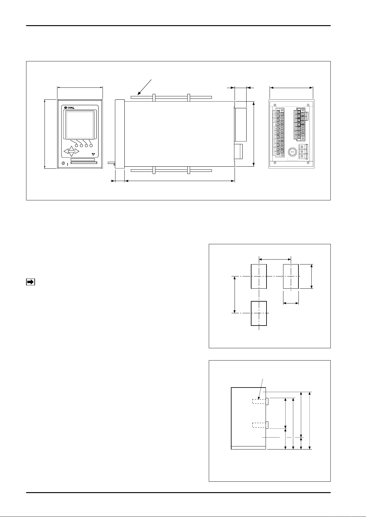
3. INSTALLATION
3.1 Outline Dimensions
All dimensions in millimeters
Hold-down Fitting
Fig. 3.1 Outline Dimensions
3.2 Installation
3.2.1 Installation Location
Select an installation site where:
(1) Mechanical vibration, shock and corrosive gases are
negligible.
(2) Air is dry and temperature at room temperature and
stable.
NOTE: Although the manufacturer guarantees stated
performance at ambient temperatures up to
+50°C, it is recommended that the instrument
be placed in service at room temperature.
(3) Provide a sufficient working space behind the instru-
ment - at least 50 centimeters from the back panel of
the instrument to facilitate wiring and servicing.
3.2.2 Panel
(1) Use a rigid steel sheet with a minimum thickness of 1.6
millimeters. 3.2mm thick is recommended.
(2) If it is required to install instruments alongside each
other, dimensions in Fig.3.2 are suggested.
(3) Recommended mounting height is given in Fig. 3.3.
Fig. 3.2 Panel Cut
3.2.3 Installation
(1) Front mount the instrument through the cutout in the
panel.
(2) Fit the furnished enclosure hold-down fittings into the
top and bottom slots in the enclosure and, confirming
that the instrument is positioned horizontal, secure the
instrument to the panel with hold-down fittings (Fig. 3.1).
Fig. 3.3 Instrument Mounting Height
E-886-2-E
TB
1
TB
2
1
2
3
TB
3
PLS OUT3 TEMP IN TEMP IN FLOW IN
0V
+− B bA+−
+− −+−
+−+− +−
+−
SIG SUP
0V SIG SUP
SUP
ANA OUT
GND POWER
N
(
−
)
H
(
+
)
PRESS INPLS OUT1
COMM1
COMM2
TEMP
PLS OUT2
1/1
OUT
DENSITY IN
4. WIRING
(See the Wiring "Guidelines" in the instruction manual of the companion pulse generator.)
4.1 Field Wiring Cables
(1) Use electrostatically shielded, polyethylene insulated, vinyl sheathed control cables (CEVS, 1.25-2
mm, 2-conductor or 3-conductor), or equivalent, for input signal cables from the flowmeter.
For output signal cables, use insulated vinyl sheathed cables (CVV, CVS ... JIS C 3401).
(2) Ground the end of shield wire to "G" terminal of the instrument. At the sensor end, leave the end of
shield wire unconnected.
4.2 Wiring Connections
(1) Field wiring through a conduit is recommended.
NOTE: In routing field wiring, use a separate conduit for power cable from other signal cables to
eliminate the possibility of stray current pickup.
(2) Separate field wiring from other power lines and power circuits to minimize the possibility of inductive
interference.
(3) Using crimp-type lugs for wiring, ensure good electrical coannections.
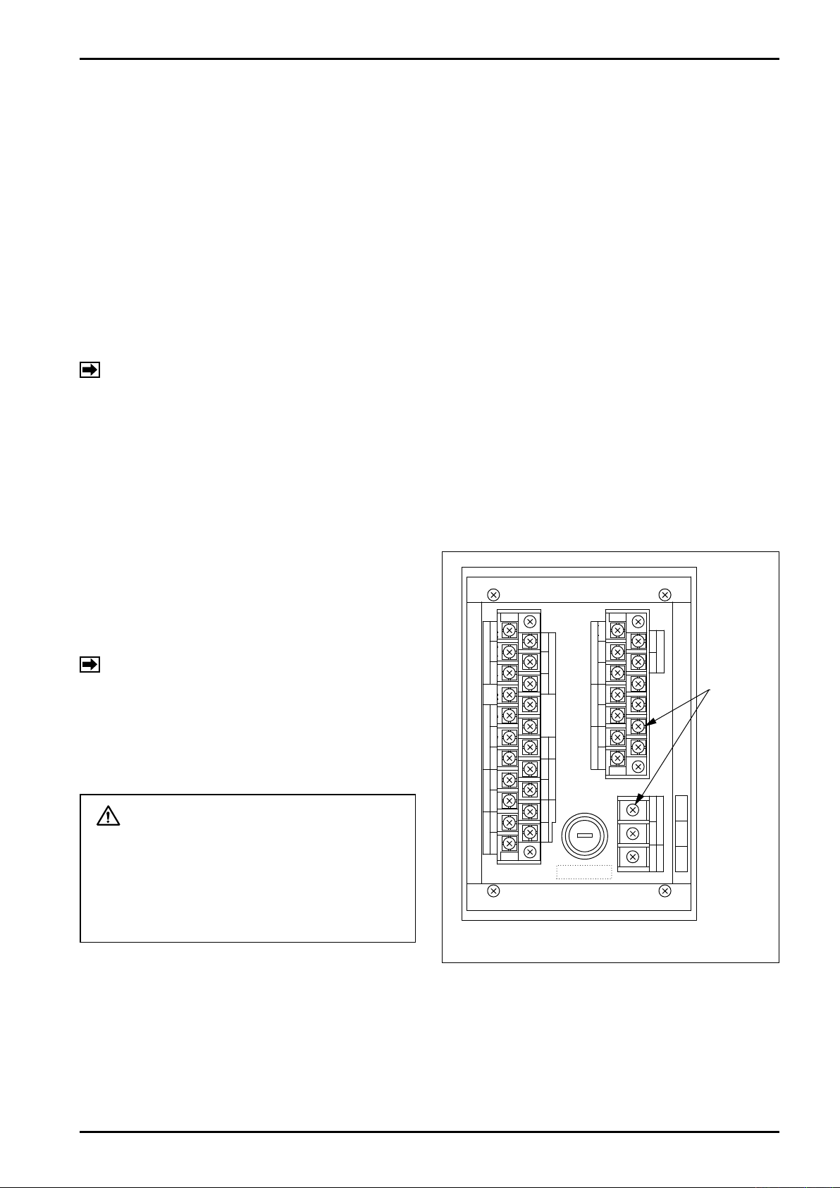
Terminals are found on the back of the instrument (Fig. 4.1).
4.3 Description of Terminal Blocks for External Connections
Terminal blocks for external connections (TB1, TB2,
and TB3) are found on the back of the instrument
as shown in Fig. 4.1. Identification of terminals
and connection method appear in Section 4.3.1
"Terminal Identifications (1) and (2)" that follow.
NOTE: TB1 and TB2 terminal numbers are
indicated on the side of terminal blocks.
CAUTION
Make wiring connections upon confirmation of the validity of flowmeter (pulse
generator) to receiving instrument combination by their product code number,
instrument number, etc.
Fig. 4.1 Terminal Blocks for Ext. Connections
Terminal
Screws
(M3.5)

E-886-2-E
4.3.1 Description of Terminals
(1) Terminal Identification
Table 4.1 EL4301 Terminal Identification
TB1
No. Label No. Label
1 12 SUP.
2 13 SIG.
3 14 0V
4 15
5 b
6 B 17 - Temp. in
7 A 18 +
8 + 19 -
9 - 20 +
10 +
11 -
Temp. in
Alarm out 3
16
21 -
Density in
Comm 1
※
Comm 2
※
No. Label No. Label
1 8 +
2 9 -
3 10
4 +
5 - 12
6 +
7 -
Analog out
Alarm out 1
TB2
11
13
1 H (+)
2 N (-)
3 GND
Alarm out 2
TB3
Power
NOTE ※: Model provided with communication interface.
NOTE: If transmitter (MT9411) temperature terminals (TEMP. ②) are used, shortcircuit TB1-14 and TB1-17.
Table 4.2 EL4311 Terminal Identification
TB1
No. Label No. Label
1 SUP.
2 SIG. 13 SIG.
3 0V 14 0V
4 OUT 1/1 15
5 b
6 B 17 - Temp. in
7 A 18 +
8 + 19 -
9 - 20 +
10 +
11 -
Flow in
Temp. in
Alarm out
12 SUP.
16
21 -
Density in
Comm 1
※
Comm 2
※
NOTE ※: Model provided with communication interface.
No. Label No. Label
1 8 +
2 9 -
3 10
4 +
5 - 12
6 +
7 -
Analog out
Pulse out 1
TB2
11
13
1 H (+)
2 N (-)
3 GND
Pulse out 1
TB3
Power
NOTE: If transmitter (MT9411) temperature terminals (TEMP. ②) are used, shortcircuit TB1-14 and TB1-17.
Table 4.3 EL4321 and EL4331 Terminal Identification
TB1
No. Label No. Label
1 12 SUP.
2 13 SIG.
3 14 0V
4 15
5 b
6 B 17 - Temp. in
7 A 18 +
8 + 19 -
9 - 20 +
10 +
11 -
Temp. in
Alarm out
16
21 -
Density in
Comm 1
※
Comm 2
※
No. Label No. Label
1 SUP.
2 + 9 -
3 - 10
4 +
5 - 12
6 +
7 -
Press. in
(EL4321 only)
Analog out
Pulse out 1
NOTE ※: Model provided with communication interface.
NOTE ※1: If 2-wire pressure transmitter is directly coupled, use TB2-1→(+); TB2-2→(-).
(※1)
TB2
8 +
11
13
1 H (+)
2 N (-)
3 GND
Pulse out 2
TB3
Power
 Loading...